EP3705709A1 - Kraftstoffeinspritzungsteuerungsvorrichtung - Google Patents
Kraftstoffeinspritzungsteuerungsvorrichtung Download PDFInfo
- Publication number
- EP3705709A1 EP3705709A1 EP18873169.9A EP18873169A EP3705709A1 EP 3705709 A1 EP3705709 A1 EP 3705709A1 EP 18873169 A EP18873169 A EP 18873169A EP 3705709 A1 EP3705709 A1 EP 3705709A1
- Authority
- EP
- European Patent Office
- Prior art keywords
- injection
- fuel
- fuel pressure
- timing
- time period
- Prior art date
- Legal status (The legal status is an assumption and is not a legal conclusion. Google has not performed a legal analysis and makes no representation as to the accuracy of the status listed.)
- Pending
Links
- 239000000446 fuel Substances 0.000 title claims abstract description 540
- 239000007924 injection Substances 0.000 title claims abstract description 529
- 238000002347 injection Methods 0.000 title claims abstract description 529
- 238000002485 combustion reaction Methods 0.000 claims abstract description 43
- 238000009825 accumulation Methods 0.000 claims abstract description 24
- 230000006835 compression Effects 0.000 description 5
- 238000007906 compression Methods 0.000 description 5
- 238000006243 chemical reaction Methods 0.000 description 4
- 230000007423 decrease Effects 0.000 description 4
- 238000001514 detection method Methods 0.000 description 3
- 239000002828 fuel tank Substances 0.000 description 3
- 239000003502 gasoline Substances 0.000 description 3
- 230000008901 benefit Effects 0.000 description 2
- 238000010586 diagram Methods 0.000 description 2
- 238000012986 modification Methods 0.000 description 2
- 230000004048 modification Effects 0.000 description 2
- 230000001052 transient effect Effects 0.000 description 2
- 230000000694 effects Effects 0.000 description 1
- 230000006870 function Effects 0.000 description 1
- 238000000034 method Methods 0.000 description 1
- 238000003825 pressing Methods 0.000 description 1
- 230000001360 synchronised effect Effects 0.000 description 1
Images


Classifications
-
- F—MECHANICAL ENGINEERING; LIGHTING; HEATING; WEAPONS; BLASTING
- F02—COMBUSTION ENGINES; HOT-GAS OR COMBUSTION-PRODUCT ENGINE PLANTS
- F02D—CONTROLLING COMBUSTION ENGINES
- F02D41/00—Electrical control of supply of combustible mixture or its constituents
- F02D41/30—Controlling fuel injection
- F02D41/38—Controlling fuel injection of the high pressure type
- F02D41/40—Controlling fuel injection of the high pressure type with means for controlling injection timing or duration
- F02D41/401—Controlling injection timing
-
- F—MECHANICAL ENGINEERING; LIGHTING; HEATING; WEAPONS; BLASTING
- F02—COMBUSTION ENGINES; HOT-GAS OR COMBUSTION-PRODUCT ENGINE PLANTS
- F02D—CONTROLLING COMBUSTION ENGINES
- F02D41/00—Electrical control of supply of combustible mixture or its constituents
- F02D41/30—Controlling fuel injection
- F02D41/38—Controlling fuel injection of the high pressure type
- F02D41/40—Controlling fuel injection of the high pressure type with means for controlling injection timing or duration
-
- F—MECHANICAL ENGINEERING; LIGHTING; HEATING; WEAPONS; BLASTING
- F02—COMBUSTION ENGINES; HOT-GAS OR COMBUSTION-PRODUCT ENGINE PLANTS
- F02B—INTERNAL-COMBUSTION PISTON ENGINES; COMBUSTION ENGINES IN GENERAL
- F02B75/00—Other engines
- F02B75/16—Engines characterised by number of cylinders, e.g. single-cylinder engines
- F02B75/18—Multi-cylinder engines
-
- F—MECHANICAL ENGINEERING; LIGHTING; HEATING; WEAPONS; BLASTING
- F02—COMBUSTION ENGINES; HOT-GAS OR COMBUSTION-PRODUCT ENGINE PLANTS
- F02M—SUPPLYING COMBUSTION ENGINES IN GENERAL WITH COMBUSTIBLE MIXTURES OR CONSTITUENTS THEREOF
- F02M55/00—Fuel-injection apparatus characterised by their fuel conduits or their venting means; Arrangements of conduits between fuel tank and pump F02M37/00
- F02M55/02—Conduits between injection pumps and injectors, e.g. conduits between pump and common-rail or conduits between common-rail and injectors
- F02M55/025—Common rails
-
- F—MECHANICAL ENGINEERING; LIGHTING; HEATING; WEAPONS; BLASTING
- F02—COMBUSTION ENGINES; HOT-GAS OR COMBUSTION-PRODUCT ENGINE PLANTS
- F02D—CONTROLLING COMBUSTION ENGINES
- F02D2200/00—Input parameters for engine control
- F02D2200/02—Input parameters for engine control the parameters being related to the engine
- F02D2200/06—Fuel or fuel supply system parameters
- F02D2200/0602—Fuel pressure
-
- F—MECHANICAL ENGINEERING; LIGHTING; HEATING; WEAPONS; BLASTING
- F02—COMBUSTION ENGINES; HOT-GAS OR COMBUSTION-PRODUCT ENGINE PLANTS
- F02D—CONTROLLING COMBUSTION ENGINES
- F02D2250/00—Engine control related to specific problems or objectives
- F02D2250/04—Fuel pressure pulsation in common rails
-
- F—MECHANICAL ENGINEERING; LIGHTING; HEATING; WEAPONS; BLASTING
- F02—COMBUSTION ENGINES; HOT-GAS OR COMBUSTION-PRODUCT ENGINE PLANTS
- F02D—CONTROLLING COMBUSTION ENGINES
- F02D2250/00—Engine control related to specific problems or objectives
- F02D2250/31—Control of the fuel pressure
-
- F—MECHANICAL ENGINEERING; LIGHTING; HEATING; WEAPONS; BLASTING
- F02—COMBUSTION ENGINES; HOT-GAS OR COMBUSTION-PRODUCT ENGINE PLANTS
- F02D—CONTROLLING COMBUSTION ENGINES
- F02D41/00—Electrical control of supply of combustible mixture or its constituents
- F02D41/30—Controlling fuel injection
- F02D41/38—Controlling fuel injection of the high pressure type
- F02D41/40—Controlling fuel injection of the high pressure type with means for controlling injection timing or duration
- F02D41/402—Multiple injections
-
- Y—GENERAL TAGGING OF NEW TECHNOLOGICAL DEVELOPMENTS; GENERAL TAGGING OF CROSS-SECTIONAL TECHNOLOGIES SPANNING OVER SEVERAL SECTIONS OF THE IPC; TECHNICAL SUBJECTS COVERED BY FORMER USPC CROSS-REFERENCE ART COLLECTIONS [XRACs] AND DIGESTS
- Y02—TECHNOLOGIES OR APPLICATIONS FOR MITIGATION OR ADAPTATION AGAINST CLIMATE CHANGE
- Y02T—CLIMATE CHANGE MITIGATION TECHNOLOGIES RELATED TO TRANSPORTATION
- Y02T10/00—Road transport of goods or passengers
- Y02T10/10—Internal combustion engine [ICE] based vehicles
- Y02T10/40—Engine management systems
Definitions
- the present disclosure relates to a fuel injection control device for a fuel injection system that injects fuel using high-pressure fuel accumulated in an accumulation container.
- high-pressure fuel accumulated in an accumulation container is injected from a fuel injection valve into the internal combustion engine.
- an injection rate at the time of fuel injection depends on a fuel pressure in the accumulation container. Therefore, the fuel pressure is detected with a pressure sensor provided in the accumulation container and an injection condition is adjusted based on the detected fuel pressure.
- Patent Literature 1 discloses that a pressure sensor detecting a discharge pressure of a fuel pump is installed and a fuel injection time period of a fuel injection valve is corrected based on a difference between a target fuel pressure that is set according to an operation state of an internal combustion engine as a destination of fuel supply and an actual fuel pressure detected with the pressure sensor.
- an injection quantity and an injection start timing are computed before fuel injection is performed with a fuel injection valve.
- an error may arise between a required injection quantity and an actual injection quantity.
- an error in injection quantity may occur when a fuel pressure varies after fuel is discharged from a fuel pump before fuel injection with a fuel injection valve.
- a fuel injection control device is for a fuel injection system, which includes an accumulation container configured to accumulate high-pressure fuel, a fuel pump configured to pressure-feed fuel to the accumulation container, a fuel injection valve configured to inject high-pressure fuel accumulated in the accumulation container into a cylinder of an internal combustion engine, and the fuel pressure sensor configured to detect a fuel pressure in the accumulation container.
- the fuel injection control device comprises a fuel pressure acquisition unit configured to acquire the fuel pressure detected with the fuel pressure sensor.
- the fuel injection control device further comprises an injection control unit configured to control fuel injection with the fuel injection valve.
- the injection control unit includes a reference computation unit configured to compute a required injection quantity and an injection start timing based on an operation state of the internal combustion engine at a predetermined reference computation timing, which is set for each combustion cycle of the internal combustion engine, and further to compute an injection time period based on the fuel pressure acquired by the fuel pressure acquisition unit at the reference computation timing.
- the injection control unit further includes a correction unit configured to correct the injection time period based on the fuel pressure acquired by the fuel pressure acquisition unit at the injection start timing.
- the injection start timing and the injection time period are first set by the reference computation unit and thereafter the injection time period is corrected by the correction unit based on the fuel pressure actually measured at the injection start timing. For this reason, start of injection at an appropriate timing and accurate control of the fuel injection quantity using the fuel pressure actually measured at the injection start timing can be both achieved.
- a fuel injection control device in this embodiment is a control device that controls a fuel injection system 1 for an internal combustion engine 40 that is a direct injection type 4-cylinder gasoline engine (multi-cylinder internal combustion engine).
- the fuel injection system 1 is an accumulator fuel injection system accumulating high-pressure fuel and includes: a fuel tank 33; a feed pump 32; a high-pressure fuel pump 30; an accumulation container 20; a fuel injection valve 10; and various sensors including a fuel pressure sensor 21.
- the feed pump 32 draws fuel from the fuel tank 33 and supplies the fuel to the high-pressure fuel pump 30.
- the high-pressure fuel pump 30 pressure-feeds fuel supplied from the fuel tank 33 by the feed pump 32 to the accumulation container 20.
- the high-pressure fuel pump 30 draws and pressurizes fuel by using a plunger that reciprocates in a housing in conjunction with a crank shaft of the internal combustion engine 40 and supplies the fuel to the accumulation container 20.
- the high-pressure fuel pump 30 discharges fuel, for example, twice in one turn of the crank shaft.
- the accumulation container 20 accumulates and holds fuel supplied from the high-pressure fuel pump 30.
- the fuel pressure sensor 21 is installed, and the fuel pressure sensor 21 detects a fuel pressure (actual pressure) in the accumulation container 20.
- the fuel injection valve 10 in a number equivalent to a number of cylinders is connected via a fuel line to the accumulation container 20.
- the fuel injection valves 10 inject fuel accumulated and held in the accumulation container 20 into respective cylinders.
- Each fuel injection valve 10 is a publicly known electromagnetically driven or piezoelectrically driven valve that opens and closes a nozzle needle by controlling the fuel pressure in a control chamber applying pressure to the nozzle needle in a valve closing direction. An injection quantity of injected fuel is increased with increase in valve opening period of the fuel injection valve 10.
- the fuel injection valve 10 provided for each of the four cylinders performs fuel injection at a 180° CA cycle in predetermined order.
- the high-pressure fuel pump 30 also performs fuel discharge at the same 180 ° CA cycle. That is, fuel injection of the fuel injection valves 10 and fuel discharge of the high-pressure fuel pump 30 are synchronized with each other, and the fuel injection valve 10 of each cylinder is identical in periodical relation of fuel injection with fuel discharge by the high-pressure fuel pump 30.
- ECU 50 is an electronic control device including a publicly known microcomputer or the like including CPU, such memory as ROM and RAM, an I/O device, and the like, and the fuel injection control device includes the ECU 50.
- the ECU 50 is inputted with detection signals from a revolution speed sensor 41 that detects an engine revolution speed and detection signals from an air quantity sensor 42 that detects an intake air quantity as an engine load in addition to detection signals from the above-mentioned fuel pressure sensor 21.
- the ECU 50 executes a program stored in ROM to control driving of the fuel injection valves 10 and the high-pressure fuel pump 30.
- the ECU 50 sets a target fuel pressure based on an engine operation state including the engine revolution speed, the engine load, and the like and further feedback-controls a quantity of fuel discharge by the high-pressure fuel pump 30 based on a difference between a target fuel pressure and an actual fuel pressure detected with the fuel pressure sensor 21.
- the ECU 50 has, as functions related to fuel injection control, a fuel pressure acquisition unit 51 that acquires the fuel pressure detected with the fuel pressure sensor 21 and an injection control unit 52 that controls fuel injection with the fuel injection valve 10 of each cylinder.
- the injection control unit 52 includes a reference computation unit 53.
- the reference computation unit 53 computes a required injection quantity and an injection start timing based on an engine operation state including the engine revolution speed, the engine load, and the like at a predetermined reference computation timing that is set for each combustion cycle of the internal combustion engine 40.
- the reference computation unit further computes an injection time period Ti that is an energization time for each fuel injection valve 10, or a duration of an injection pulse, based on the fuel pressure Pa acquired by the fuel pressure acquisition unit 51 at the reference computation timing.
- fuel injection for example, 600° CA before compression TDC for each cylinder is taken as a reference computation timing to compute the required injection quantity, the injection start timing, and the injection time period Ti.
- the fuel pressure can be varied due to fuel discharge of the high-pressure fuel pump 30 or the like during a period from the reference computation timing to the injection start time. An error in injection quantity due to such a variation in fuel pressure is apprehended.
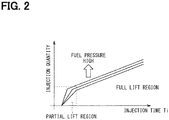
- an amount of change in injection quantity Q against in an amount of change in injection time period Ti is increased as compared with an ordinary region.
- an amount of change in injection quantity Q against an amount of change in injection time period Ti is increased with increase in fuel pressure. That is, in a minute injection region, an amount of deviation in injection quantity against an amount of deviation in injection time period Ti increases as compared with an ordinary region and further an amount of deviation in injection quantity Q tends to increase with increase in fuel pressure.
- the injection control unit 52 includes a correction unit 54.
- the correction unit 54 corrects the injection time period Ti based on the fuel pressure Pb acquired by the fuel pressure acquisition unit 51 at the injection start time behind the reference computation timing. In this case, at the reference computation timing as an injection quantity computation time, the fuel pressure Pa at that reference computation timing is reflected, and the required injection quantity is converted on a time basis, and the injection time period Ti of the fuel injection valve 10 is thereby computed. Thereafter, the injection time period Ti is corrected based on the fuel pressure Pb at the injection start timing.
- the correction may not be completed before an end of fuel injection (a falling edge of an injection pulse) of this time.
- the injection time period Ti is slightly shorter, a correction time cannot be ensured, and correction may not be completed before the end of the injection time period Ti.
- the ECU 50 is provided with a storage processing unit 55, and the storage processing unit 55 computes, as a reference fuel pressure difference ⁇ P1, a difference between the fuel pressure Pa acquired at the reference computation timing and the fuel pressure Pb acquired at the injection start timing and stores the reference fuel pressure difference ⁇ P1 in a memory 56.
- the memory 56 is a storage unit including, for example, RAM.
- the reference computation unit 53 computes the injection time period Ti based on the fuel pressure Pa acquired at the reference computation timing and the reference fuel pressure difference ⁇ P1. This is equivalent to that at the reference computation timing, the fuel pressure at the injection start timing is estimated and a result of this estimation is reflected to compute the injection time period Ti. In this case, even when correction of the injection time period Ti has not been completed after start of injection, a value closer to the fuel pressure Pb at the injection start timing of the present cycle can be used to compute the injection time period.
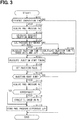
- FIG. 3 is a flowchart showing the fuel injection control processing performed by the ECU 50. This processing is repeatedly performed by the ECU 50 at predetermined intervals.
- Step S101 first, whether the present time is the reference computation timing or not is determined.
- the reference computation timing is set as a predetermined timing (for example, 600° CA before compression TDC) for each combustion cycle of each cylinder.
- the operation proceeds to Step S102 and when the present time is not the reference computation timing, the operation proceeds to Step S109.
- Step S102 the fuel pressure detected with the fuel pressure sensor 21 is acquired as the fuel pressure Pa.
- the required injection quantity is computed based on the engine revolution speed and the engine load.
- Step S104 subsequently, whether the reference fuel pressure difference ⁇ P1 stored in the memory 56 is to be read or not is determined.
- the reference fuel pressure difference ⁇ P1 is stored in the memory 56 at this time and the reference fuel pressure difference ⁇ P1 is computed in the preceding combustion cycle, a conclusion that the reference fuel pressure difference ⁇ P1 can be read is made.
- An affirmative determination is made at Step S104 and the operation proceeds to Step S105.
- the reference fuel pressure difference ⁇ P1 is not stored in the memory 56 or when the reference fuel pressure difference ⁇ P1 is stored but is not computed in the preceding combustion cycle, a conclusion that the reference fuel pressure difference ⁇ P1 cannot be read is made.
- a negative determination is made at Step S104 and the operation proceeds to Step S106.
- Step S104 it is advisable to determine whether the reference fuel pressure difference ⁇ P1 computed in the preceding combustion cycle is stored in the memory 56 with respect to an identical fuel injection valve 10.
- the injection time period Ti is computed based on a result of conversion of the required injection quantity into a time period, the fuel pressure Pa, and the reference fuel pressure difference ⁇ P1.
- an addition value (Pa + ⁇ P1) of the fuel pressure Pa and the reference fuel pressure difference ⁇ P1 is used to compute the injection time period Ti.
- the injection time period Ti is computed based on a result of conversion of the required injection quantity into the time period and the fuel pressure Pa.
- the injection start timing is computed based on the engine revolution speed and the engine load.
- an injection pulse set according to the injection time period Ti is set on an output circuit. As a result, an injection pulse is generated at desired the injection start timing. Thereafter, the injection pulse is caused to fall when the injection time period Ti has passed.
- Step S109 whether the present time is the injection start time or not is determined.
- the operation proceeds to Step S110, and when the present time is not the injection start time, the present processing is once terminated.
- the fuel pressure detected with the fuel pressure sensor 21 is acquired as the fuel pressure Pb.
- the fuel pressure Pb may be the fuel pressure detected before the fuel pressure is reduced from that at start of fuel injection at the injection start time or immediately before the injection start time.
- Step S111 subsequently, whether the injection time period Ti can be corrected based on the fuel pressure Pb within the present injection time period Ti or not is determined.
- the operation proceeds to Step S112; and when the injection time period is uncorrectable, the operation proceeds to Step S113 with Step S112 skipped.
- the injection time period Ti is corrected based on the fuel pressure Pb.
- correction may be made by replacement with the injection time period Ti computed based on the fuel pressure Pb or may be made using an amount of change in injection time period Ti computed based on the reference fuel pressure difference ⁇ P1 that is a difference between the fuel pressure Pa at the reference computation timing and the fuel pressure Pb at the injection start timing.
- ⁇ P1 a difference between the fuel pressure Pa at the reference computation timing and the fuel pressure Pb at the injection start timing.
- Step S105 When the injection time period Ti is computed by reflecting the reference fuel pressure difference ⁇ P1 in the memory 56 at the reference computation timing (Step S105), it is advisable to correct the injection time period Ti based on an amount equivalent to a difference between the reference fuel pressure difference ⁇ P1 in the memory 56 and the present reference fuel pressure difference ⁇ P1.
- the operation of Step S111 may be omitted. For example, in cases where the operation of Step S111 is not performed and where the injection time period Ti is corrected based on the fuel pressure Pb, injection is terminated based on the corrected injection time period Ti when the correction is not too late and injection is terminated based on the injection time period Ti before correction when the correction is too late.
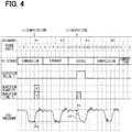
- FIG. 4 is a timing chart illustrating fuel injection performed in a predetermined cylinder (first cylinder) of the internal combustion engine 40.
- first cylinder predetermined cylinder
- FIG. 4 boundaries and crank angle value of first to fourth cylinders are indicated and further strokes of the first cylinder, an injection pulse, a timing of required injection quantity computation, and a timing of injection time period Ti computation. Variation in fuel pressure is also shown.
- the crank angle value is given as numbers of 0 to 23, for example, for each 30° CA within a period during which the crank shaft is turned twice (within 720° CA).
- a timing of required injection quantity computation and a timing of injection time period Ti computation are shown in positions corresponding to crank angle value for convenience in explanation.
- the fuel pressure repeatedly increases and decreases. That is, the fuel pressure increases at a timing corresponding to fuel discharge of the high-pressure fuel pump 30 and the fuel pressure decreases at a timing corresponding to fuel injection of each fuel injection valve 10.
- Time t1 is a reference injection time period and at time t1, the fuel pressure Pa is acquired, and further the required injection quantity and the injection time period Ti are computed.
- Time t2 is an the injection start timing and at time t2, the fuel pressure Pb is acquired, and the injection time period Ti is corrected based on the acquired fuel pressure Pb.
- the fuel pressure increases twice due to fuel discharge of the high-pressure fuel pump 30 and further the fuel pressure decreases once due to fuel injection of another cylinder (specifically, second cylinder). For this reason, a difference is produced between the fuel pressures Pa and Pb but the injection time period Ti is corrected according to the difference in fuel pressure.
- the injection time period Ti when the injection time period Ti is relatively short, correction based on the fuel pressure Pb may not be completed. For this reason, at time t2 as the injection start time, the reference fuel pressure difference ⁇ P1 that is a difference between the fuel pressure Pa at the reference computation timing and the fuel pressure Pb at the injection start timing is stored in the memory 56, and at the next reference injection time period (equivalent to time t1), the injection time period Ti is computed based on the fuel pressure Pa and the reference fuel pressure difference ⁇ P1.
- Ti correction based on the fuel pressure Pb can be made by estimation even though Ti correction based on the fuel pressure Pb cannot be made after start of subsequent injection.
- the Injection start timing and the injection time period Ti are first set by the reference computation unit 53 and thereafter, the injection time period Ti is corrected by the correction unit 54 based on the fuel pressure Pb actually measured at the injection start timing. For this reason, start of injection at an appropriate timing and accurate control of a fuel injection quantity using the fuel pressure actually measured at the injection start timing can be both achieved.
- an amount of deviation in injection quantity Q can be larger against an amount of deviation in injection time period Ti.
- the above embodiment may be effective especially in such fuel injection in a minute injection region.
- the correction may not be completed before an end of fuel injection (a falling edge of an injection pulse) of this time.
- a difference between the fuel pressure Pa acquired at the reference computation timing and the fuel pressure Pb acquired at the injection start timing is stored as the reference fuel pressure difference ⁇ P1 in the memory 56; and at the next reference computation timing, the injection time period Ti is computed based on the fuel pressure Pa at that time and the reference fuel pressure difference ⁇ P1 stored in the memory 56.
- the reference fuel pressure difference ⁇ P1 computed in the preceding combustion cycle of an identical fuel injection valve 10 is used as the reference fuel pressure difference ⁇ P1.
- the reference fuel pressure difference ⁇ P1 computed in the preceding combustion cycle of an identical fuel injection valve 10 can be considered to have no difference or little difference from the reference fuel pressure difference ⁇ P1 of the present time. For this reason, appropriate fuel injection can be performed regardless of transient variation in fuel pressure.
- the ECU 50 is capable of performing more than one time of fuel injection in one combustion cycle of the internal combustion engine 40 as split injection.
- Split injection is performed in such a pattern as 2-stage injection, 3-stage injection, 4-stage injection, or the like.
- fuel injection can be performed twice in an intake stroke and once in a compression stroke.
- the fuel injection valves 10 of different cylinders can overlap in fuel injection period. Further, a fuel injection period and the fuel pressure-feed period of the high-pressure fuel pump 30 can overlap with each other. For this reason, to grasp (estimate) the fuel pressure in injection in each stage of multi-stage injection at the reference computation timing, it is desirable to consider an amount of fuel pressure drop caused in each injection in addition to an amount of change from the fuel pressure at the reference computation timing.
- the storage processing unit 55 in the ECU 50 computes, as a before-after-injection fuel pressure difference ⁇ P2, the fuel pressure difference between before fuel injection and after fuel injection for each injection of split injection and stores the computed fuel pressure difference in the memory 56.
- the reference computation unit 53 computes the injection time period Ti based on the fuel pressure Pa acquired by the fuel pressure acquisition unit 51 at the reference computation timing, the reference fuel pressure difference ⁇ P1, and the before-after-injection fuel pressure difference ⁇ P2 stored in the memory 56.
- the storage processing unit 55 With respect to computation of the before-after-injection fuel pressure difference ⁇ P2, it is advisable to cause the storage processing unit 55 to compute, as the before-after-injection fuel pressure difference ⁇ P2, a difference between the fuel pressure acquired by the fuel pressure acquisition unit 51 at the injection start timing of each injection of split injection and the fuel pressure acquired by the fuel pressure acquisition unit 51 at the injection start timing of the subsequent injection.
- the storage processing unit 55 computes before-after-injection fuel pressure differences ⁇ P21, ⁇ P22 between before fuel injection and after fuel injection with respect to first-stage injection and second-stage injection. That is, a difference between the fuel pressure Pb1 acquired at the injection start timing of the first-stage injection and the fuel pressure Pb2 acquired at the injection start timing of the second-stage injection is computed as the fuel pressure difference ⁇ P21 between before and after the first-stage injection; and a difference between the fuel pressure Pb2 acquired at the injection start timing of the second-stage injection and the fuel pressure Pb3 acquired at the injection start timing of the third-stage injection is computed as the fuel pressure difference ⁇ P22 between before and after the second-stage injection.
- FIG. 5 is a flowchart of fuel injection control processing in this embodiment. This processing is on the assumption of 3-stage split injection and is repeatedly performed at predetermined intervals by the ECU 50 when the 3-stage split injection is performed.
- FIG. 5 is drawn by partly modifying FIG. 3 and a description of the same operation as in FIG. 3 will be simplified.
- Steps S201 to S203 in FIG. 5 the fuel pressure detected with the fuel pressure sensor 21 is acquired as the fuel pressure Pa on condition that the present time is the reference computation timing and further, the required injection quantity is computed (same as Steps S101 to S103 in FIG. 3 ). Especially in split injection, at Step S203, the required injection quantity is split to compute an injection quantity of each stage.
- Step S204 subsequently, whether the reference fuel pressure difference ⁇ P1 and the before-after-injection fuel pressure differences ⁇ P21, ⁇ P22 stored in the memory 56 are to be read or not is determined.
- the reference fuel pressure difference ⁇ P1 and the before-after-injection fuel pressure differences ⁇ P21, ⁇ P22 are stored in the memory 56 at this time and these differences are computed in the preceding combustion cycle, a conclusion that the reference fuel pressure difference ⁇ P1 and the before-after-injection fuel pressure differences ⁇ P21, ⁇ P22 can be read is made.
- An affirmative determination is made at Step S204 and the operation proceeds to Step S205.
- Step S204 it is advisable to determine whether the reference fuel pressure difference ⁇ P1 and the before-after-injection fuel pressure differences ⁇ P21, ⁇ P22 computed in the preceding combustion cycle with respect to an identical fuel injection valve 10 are stored in the memory 56 or not.
- the injection time period Ti1, Ti2, Ti3 of each injection is computed based on a result of conversion of the required injection quantity into the time period, the fuel pressure Pa, the reference fuel pressure difference ⁇ P1, and the before-after-injection fuel pressures ⁇ P21, ⁇ P22.
- the injection time period Ti1 of first-stage injection is computed as an addition value (Pa + ⁇ P1) of the fuel pressure Pa and the reference fuel pressure difference ⁇ P1.
- the injection time period Ti2 of second-stage injection is computed as an addition value (Pa + ⁇ P1 + ⁇ P21) of the fuel pressure Pa, the reference fuel pressure difference ⁇ P1, and the before-after-injection fuel pressure difference ⁇ P21.
- the injection time period Ti3 of third-stage injection is computed as an addition value (Pa + ⁇ P1 + ⁇ P21 + ⁇ P22) of the fuel pressure Pa, the reference fuel pressure difference ⁇ P1, and the before-after-injection fuel pressure differences ⁇ P21, ⁇ P22.
- the injection time period Ti is computed based on a result of conversion of the required injection quantity into the time period and the fuel pressure Pa (same as Step S106 in FIG. 3 ).
- Steps S207 and S208 subsequently, the injection start timing is computed and an injection pulse is set on an output circuit (same as Steps S107 and S108 in FIG. 3 ).
- Step S209 whether the present time is any injection start time of each injection of multi-stage injection or not is determined.
- the operation proceeds to Step S210; and when the present time is not any injection start time, the present processing is once terminated.
- the fuel pressure detected with the fuel pressure sensor 21 is acquired as the fuel pressure Pb for each injection.
- the fuel pressure Pb1 is acquired; in the case of second-stage injection, the fuel pressure Pb2 is acquired; and in the case of third-stage injection, the fuel pressure Pb3 is acquired.
- the before-after-injection fuel pressure difference ⁇ P2 is computed.
- the fuel pressure difference ⁇ P21 between before and after first-stage injection is computed by "Pb2 - Pb1," and the fuel pressure difference ⁇ P22 between before and after second-stage injection is computed by "Pb3 - Pb2.”
- Step S212 subsequently, whether the injection time period Ti can be corrected based on the fuel pressure Pb or not is determined with respect to the present injection.
- the operation proceeds to Step S213; and when the injection time period is uncorrectable, the operation proceeds to Step S214 with Step S213 skipped.
- Step S212 can also be omitted.
- the injection time period Ti is corrected based on the fuel pressure Pb.
- the injection time period Ti1 is corrected based on the fuel pressure Pb1; with respect to second-stage injection, the injection time period Ti2 is corrected based on the fuel pressure Pb2; and with respect to third-stage injection, the injection time period Ti3 is corrected based on the fuel pressure Pb3.
- correction may be made by replacement with the injection time period Ti computed based on the fuel pressure Pb or may be made using an amount of change in injection time period Ti computed based on the reference fuel pressure difference ⁇ P1 and the like.
- Step S214 subsequently, the reference fuel pressure difference ⁇ P1 and the before-after-injection fuel pressure difference ⁇ P2 are stored in the memory 56 and thereafter, the present processing is terminated.
- FIG. 6 A concrete description will be given to how the injection time period Ti is corrected when split injection is performed with reference to the timing chart in FIG. 6 .
- a discharge period of the high-pressure fuel pump 30 and a fuel injection period of the fuel injection valve 10 of each cylinder are indicated in accordance with crank angle value.
- fuel injection is dispersedly performed during a period from initial-stage fuel injection to last-stage fuel injection; therefore, overlapping with a pump discharge period and overlapping with fuel injection of any other cylinder are prone to occur.
- pump discharge and fuel injection of a second cylinder overlap with each other.
- variation in fuel pressure is complicated. That is, variation in fuel pressure may be caused by any other factor than fuel injection of a relevant cylinder.
- FIG. 6 as split injection of the first cylinder, two times of intake stroke injection (injections 1 and 2 shown in FIG. 6 ) are performed as first-stage injection and second-stage injection; and one time of compression stroke injection (INJECTION 3 shown in FIG. 6 ) is performed as third-stage injection.
- time t10 is a reference injection time period and at time t10, the fuel pressure Pa is acquired and the required injection quantity, an injection quantity of each stage, and the injection time period Ti of each stage are computed.
- the fuel pressure Pb1 is acquired and the injection time period Ti1 of first-stage injection is corrected based on the fuel pressure Pb1 (reference fuel pressure difference ⁇ P1 when an amount of change in injection time period Ti is used).
- the reference fuel pressure difference ⁇ P1 is stored in the memory 56.
- the fuel pressure Pb2 is acquired and the injection time period Ti2 of second-stage injection is corrected based on the fuel pressure Pb2 (the reference fuel pressure difference ⁇ P1 and the before-after-injection fuel pressure difference ⁇ P21 when an amount of change in injection time period Ti is used).
- the fuel pressure difference ⁇ P21 between before and after first-stage injection is stored in the memory 56.
- the fuel pressure Pb3 is acquired and the injection time period Ti3 of third-stage injection is corrected based on the fuel pressure Pb3 (the reference fuel pressure difference ⁇ P1 and the before-after-injection fuel pressure differences ⁇ P21 and ⁇ P22 when an amount of change in injection time period Ti is used).
- the fuel pressure difference ⁇ P22 between before and after second-stage injection is stored in the memory 56.
- injection time period Ti1 to Ti3 of each injection is relatively short, correction based on the fuel pressure Pb1 to Pb3 may not be completed. For this reason, at times t11 to t13 as injection start times, the reference fuel pressure difference ⁇ P1, the before-after-injection fuel pressure differences ⁇ P21 and ⁇ P22 are stored in the memory 56. At the next reference injection time period (equivalent to time t10), the injection time period Ti1 to Ti3 of each injection is computed based on the fuel pressure Pa, the reference fuel pressure difference ⁇ P1, and the before-after-injection fuel pressure differences ⁇ P21 and ⁇ P22. Thus, Ti correction based on fuel pressures Pb1 to Pb3 can be made by estimation even though Ti correction based on fuel pressures Pb1 to Pb3 cannot be made after start of each subsequent injection.
- Fuel pressure differences ⁇ P21 and ⁇ P22 between before and after first-stage injection and second-stage injection can also be computed by the following technique:
- the storage processing unit 55 computes, as the before-after-injection fuel pressure differences ⁇ P21 and ⁇ P22, differences between fuel pressures Pb1 and Pb2 acquired by the fuel pressure acquisition unit 51 at the injection start timing of each injection of split injection and fuel pressures Pc1 and Pc2 acquired by the fuel pressure acquisition unit 51 at the injection end timing and stores the computed differences.
- FIG. 7 illustrates an operation performed in this case.
- FIG. 7 is a timing chart drawn by partly modifying FIG. 6 and the modified part is only a part related to computation of the before-after-injection fuel pressure differences ⁇ P21, ⁇ P22.
Applications Claiming Priority (2)
| Application Number | Priority Date | Filing Date | Title |
|---|---|---|---|
| JP2017212611A JP6863236B2 (ja) | 2017-11-02 | 2017-11-02 | 燃料噴射制御装置 |
| PCT/JP2018/040564 WO2019088188A1 (ja) | 2017-11-02 | 2018-10-31 | 燃料噴射制御装置 |
Publications (2)
| Publication Number | Publication Date |
|---|---|
| EP3705709A1 true EP3705709A1 (de) | 2020-09-09 |
| EP3705709A4 EP3705709A4 (de) | 2020-12-09 |
Family
ID=66331987
Family Applications (1)
| Application Number | Title | Priority Date | Filing Date |
|---|---|---|---|
| EP18873169.9A Pending EP3705709A4 (de) | 2017-11-02 | 2018-10-31 | Kraftstoffeinspritzungsteuerungsvorrichtung |
Country Status (4)
| Country | Link |
|---|---|
| US (1) | US11193445B2 (de) |
| EP (1) | EP3705709A4 (de) |
| JP (1) | JP6863236B2 (de) |
| WO (1) | WO2019088188A1 (de) |
Families Citing this family (1)
| Publication number | Priority date | Publication date | Assignee | Title |
|---|---|---|---|---|
| WO2020214920A1 (en) * | 2019-04-18 | 2020-10-22 | Cummins Inc. | Apparatus, system, and method for thermal management by deploying engine fueling on demand |
Family Cites Families (16)
| Publication number | Priority date | Publication date | Assignee | Title |
|---|---|---|---|---|
| JP2991574B2 (ja) * | 1992-09-14 | 1999-12-20 | 株式会社デンソー | 内燃機関の蓄圧式燃料噴射制御装置 |
| DE4306252C1 (de) * | 1993-03-01 | 1994-05-19 | Daimler Benz Ag | Verfahren zum Betreiben einer luftverdichtenden mehrzylindrigen Einspritzbrennkraftmaschine |
| DE19726757B4 (de) * | 1997-06-24 | 2005-04-14 | Robert Bosch Gmbh | Verfahren zur Steuerung und/oder Regelung einer mit mehreren Brennräumen versehenen Brennkraftmaschine |
| JP3427683B2 (ja) | 1997-07-24 | 2003-07-22 | 日産自動車株式会社 | 内燃機関の燃料供給装置 |
| US6488012B1 (en) * | 2000-08-29 | 2002-12-03 | Ford Global Technologies, Inc. | Method and apparatus for determining fuel pressure |
| DE10342130A1 (de) * | 2003-09-12 | 2005-04-07 | Robert Bosch Gmbh | Verfahren und Vorrichtung zum Betreiben einer Brennkraftmaschine |
| JP4333635B2 (ja) * | 2005-05-24 | 2009-09-16 | 株式会社デンソー | 筒内噴射式の内燃機関の制御装置 |
| JP4428427B2 (ja) * | 2007-08-31 | 2010-03-10 | 株式会社デンソー | 燃料噴射特性検出装置及び燃料噴射指令補正装置 |
| JP4678397B2 (ja) * | 2007-10-15 | 2011-04-27 | 株式会社デンソー | 燃料噴射状態検出装置 |
| US20090326788A1 (en) * | 2008-06-25 | 2009-12-31 | Honda Motor Co., Ltd. | Fuel injection device |
| JP2010043614A (ja) * | 2008-08-14 | 2010-02-25 | Hitachi Ltd | エンジンの制御装置 |
| DE102010054997B4 (de) * | 2010-12-17 | 2012-09-13 | Iav Gmbh Ingenieurgesellschaft Auto Und Verkehr | Verfahren zur Erkennung von irregulären Verbrennungsvorgängen bei einer Verbrennungskraftmaschine |
| JP6350226B2 (ja) * | 2014-11-05 | 2018-07-04 | 株式会社デンソー | 内燃機関の燃料噴射制御装置 |
| JP6238255B2 (ja) | 2016-05-25 | 2017-11-29 | 株式会社Nexpoint | 監視カメラシステムによる監視方法及び動画分割装置 |
| JP6658592B2 (ja) | 2017-02-13 | 2020-03-04 | トヨタ自動車株式会社 | 燃料噴射制御装置 |
| JP6922713B2 (ja) * | 2017-12-13 | 2021-08-18 | トヨタ自動車株式会社 | 燃料ポンプの制御装置 |
-
2017
- 2017-11-02 JP JP2017212611A patent/JP6863236B2/ja active Active
-
2018
- 2018-10-31 EP EP18873169.9A patent/EP3705709A4/de active Pending
- 2018-10-31 WO PCT/JP2018/040564 patent/WO2019088188A1/ja unknown
-
2020
- 2020-04-22 US US16/855,104 patent/US11193445B2/en active Active
Also Published As
| Publication number | Publication date |
|---|---|
| EP3705709A4 (de) | 2020-12-09 |
| US11193445B2 (en) | 2021-12-07 |
| WO2019088188A1 (ja) | 2019-05-09 |
| US20200248644A1 (en) | 2020-08-06 |
| JP2019085892A (ja) | 2019-06-06 |
| JP6863236B2 (ja) | 2021-04-21 |
Similar Documents
| Publication | Publication Date | Title |
|---|---|---|
| JP4424395B2 (ja) | 内燃機関の燃料噴射制御装置 | |
| JP4840288B2 (ja) | 燃料噴射装置及びその調整方法 | |
| JP4026368B2 (ja) | 蓄圧式燃料噴射装置 | |
| EP1978226B1 (de) | Steuervorrichtung zur genauen Steuerung einer Kraftstoffeinspritzvorrichtung bei variablem Kraftstoffspeicherdruck | |
| US7201148B2 (en) | Pressure accumulation fuel injection controller | |
| JP4479764B2 (ja) | 燃料噴射制御装置およびそれを用いた燃料噴射システム | |
| JP5141723B2 (ja) | 内燃機関の燃料噴射制御装置 | |
| US20050081825A1 (en) | Common rail type fuel injection system | |
| EP1338781B1 (de) | Speicherkraftstoffeinspritzsystem | |
| US20150112576A1 (en) | Pump control apparatus for fuel supply system of fuel-injection engine | |
| KR100612784B1 (ko) | 축압식 연료 분사 시스템 | |
| JP5370348B2 (ja) | 内燃機関の燃料噴射制御装置 | |
| EP2546501A1 (de) | Fehlfunktionserkennungsvorrichtung für Motoren und Fehlfunktionserkennungsverfahren für Motoren | |
| US11193445B2 (en) | Fuel injection control device and method for controlling fuel injection valve | |
| JP2005146947A (ja) | 内燃機関の噴射量制御装置 | |
| JP5527338B2 (ja) | 燃料噴射制御装置 | |
| JP4470975B2 (ja) | 燃料噴射制御装置およびそれを用いた燃料噴射システム | |
| JP5565435B2 (ja) | 燃料噴射制御装置 | |
| JP4470976B2 (ja) | 燃料噴射制御装置およびそれを用いた燃料噴射システム | |
| JP2007113503A (ja) | 高圧燃料システムの信頼性評価装置 | |
| JP5664539B2 (ja) | 燃料供給システムの制御装置 | |
| JP4788700B2 (ja) | 燃料噴射制御装置およびそれを用いた燃料噴射システム | |
| JP4753078B2 (ja) | 内燃機関の制御装置 | |
| JP7006344B2 (ja) | 制御装置 | |
| JP2003227394A (ja) | 蓄圧式燃料噴射装置 |
Legal Events
| Date | Code | Title | Description |
|---|---|---|---|
| STAA | Information on the status of an ep patent application or granted ep patent |
Free format text: STATUS: THE INTERNATIONAL PUBLICATION HAS BEEN MADE |
|
| PUAI | Public reference made under article 153(3) epc to a published international application that has entered the european phase |
Free format text: ORIGINAL CODE: 0009012 |
|
| STAA | Information on the status of an ep patent application or granted ep patent |
Free format text: STATUS: REQUEST FOR EXAMINATION WAS MADE |
|
| 17P | Request for examination filed |
Effective date: 20200331 |
|
| AK | Designated contracting states |
Kind code of ref document: A1 Designated state(s): AL AT BE BG CH CY CZ DE DK EE ES FI FR GB GR HR HU IE IS IT LI LT LU LV MC MK MT NL NO PL PT RO RS SE SI SK SM TR |
|
| AX | Request for extension of the european patent |
Extension state: BA ME |
|
| STAA | Information on the status of an ep patent application or granted ep patent |
Free format text: STATUS: EXAMINATION IS IN PROGRESS |
|
| A4 | Supplementary search report drawn up and despatched |
Effective date: 20201110 |
|
| RIC1 | Information provided on ipc code assigned before grant |
Ipc: F02D 41/32 20060101ALI20201104BHEP Ipc: F02D 41/04 20060101AFI20201104BHEP Ipc: F02D 41/40 20060101ALI20201104BHEP Ipc: F02D 41/34 20060101ALI20201104BHEP Ipc: F02D 45/00 20060101ALI20201104BHEP Ipc: F02M 61/10 20060101ALI20201104BHEP Ipc: F02M 51/00 20060101ALI20201104BHEP |
|
| 17Q | First examination report despatched |
Effective date: 20201119 |
|
| DAV | Request for validation of the european patent (deleted) | ||
| DAX | Request for extension of the european patent (deleted) | ||
| GRAP | Despatch of communication of intention to grant a patent |
Free format text: ORIGINAL CODE: EPIDOSNIGR1 |
|
| STAA | Information on the status of an ep patent application or granted ep patent |
Free format text: STATUS: GRANT OF PATENT IS INTENDED |
|
| INTG | Intention to grant announced |
Effective date: 20240318 |
|
| GRAS | Grant fee paid |
Free format text: ORIGINAL CODE: EPIDOSNIGR3 |