EP3704993A1 - Stützeinrichtung - Google Patents
Stützeinrichtung Download PDFInfo
- Publication number
- EP3704993A1 EP3704993A1 EP20165962.0A EP20165962A EP3704993A1 EP 3704993 A1 EP3704993 A1 EP 3704993A1 EP 20165962 A EP20165962 A EP 20165962A EP 3704993 A1 EP3704993 A1 EP 3704993A1
- Authority
- EP
- European Patent Office
- Prior art keywords
- support device
- loading
- pressure
- support
- pressure element
- Prior art date
- Legal status (The legal status is an assumption and is not a legal conclusion. Google has not performed a legal analysis and makes no representation as to the accuracy of the status listed.)
- Granted
Links
Images


Classifications
-
- A—HUMAN NECESSITIES
- A47—FURNITURE; DOMESTIC ARTICLES OR APPLIANCES; COFFEE MILLS; SPICE MILLS; SUCTION CLEANERS IN GENERAL
- A47C—CHAIRS; SOFAS; BEDS
- A47C23/00—Spring mattresses with rigid frame or forming part of the bedstead, e.g. box springs; Divan bases; Slatted bed bases
- A47C23/06—Spring mattresses with rigid frame or forming part of the bedstead, e.g. box springs; Divan bases; Slatted bed bases using wooden springs, e.g. of slat type
- A47C23/062—Slat supports
-
- A—HUMAN NECESSITIES
- A47—FURNITURE; DOMESTIC ARTICLES OR APPLIANCES; COFFEE MILLS; SPICE MILLS; SUCTION CLEANERS IN GENERAL
- A47C—CHAIRS; SOFAS; BEDS
- A47C31/00—Details or accessories for chairs, beds, or the like, not provided for in other groups of this subclass, e.g. upholstery fasteners, mattress protectors, stretching devices for mattress nets
- A47C31/12—Means, e.g. measuring means, for adapting chairs, beds or mattresses to the shape or weight of persons
- A47C31/123—Means, e.g. measuring means, for adapting chairs, beds or mattresses to the shape or weight of persons for beds or mattresses
-
- A—HUMAN NECESSITIES
- A47—FURNITURE; DOMESTIC ARTICLES OR APPLIANCES; COFFEE MILLS; SPICE MILLS; SUCTION CLEANERS IN GENERAL
- A47C—CHAIRS; SOFAS; BEDS
- A47C19/00—Bedsteads
- A47C19/02—Parts or details of bedsteads not fully covered in a single one of the following subgroups, e.g. bed rails, post rails
- A47C19/021—Bedstead frames
- A47C19/025—Direct mattress support frames, Cross-bars
- A47C19/027—Direct mattress support frames, Cross-bars with means for preventing frame from sagging
-
- A—HUMAN NECESSITIES
- A47—FURNITURE; DOMESTIC ARTICLES OR APPLIANCES; COFFEE MILLS; SPICE MILLS; SUCTION CLEANERS IN GENERAL
- A47C—CHAIRS; SOFAS; BEDS
- A47C20/00—Head-, foot- or like rests for beds, sofas or the like
- A47C20/04—Head-, foot- or like rests for beds, sofas or the like with adjustable inclination
- A47C20/041—Head-, foot- or like rests for beds, sofas or the like with adjustable inclination by electric motors
-
- A—HUMAN NECESSITIES
- A47—FURNITURE; DOMESTIC ARTICLES OR APPLIANCES; COFFEE MILLS; SPICE MILLS; SUCTION CLEANERS IN GENERAL
- A47C—CHAIRS; SOFAS; BEDS
- A47C23/00—Spring mattresses with rigid frame or forming part of the bedstead, e.g. box springs; Divan bases; Slatted bed bases
- A47C23/06—Spring mattresses with rigid frame or forming part of the bedstead, e.g. box springs; Divan bases; Slatted bed bases using wooden springs, e.g. of slat type
- A47C23/062—Slat supports
- A47C23/066—Slat supports by chains, ropes or belts
-
- A—HUMAN NECESSITIES
- A47—FURNITURE; DOMESTIC ARTICLES OR APPLIANCES; COFFEE MILLS; SPICE MILLS; SUCTION CLEANERS IN GENERAL
- A47C—CHAIRS; SOFAS; BEDS
- A47C23/00—Spring mattresses with rigid frame or forming part of the bedstead, e.g. box springs; Divan bases; Slatted bed bases
- A47C23/06—Spring mattresses with rigid frame or forming part of the bedstead, e.g. box springs; Divan bases; Slatted bed bases using wooden springs, e.g. of slat type
- A47C23/062—Slat supports
- A47C23/067—Slat supports adjustable, e.g. in height or elasticity
-
- A—HUMAN NECESSITIES
- A47—FURNITURE; DOMESTIC ARTICLES OR APPLIANCES; COFFEE MILLS; SPICE MILLS; SUCTION CLEANERS IN GENERAL
- A47C—CHAIRS; SOFAS; BEDS
- A47C23/00—Spring mattresses with rigid frame or forming part of the bedstead, e.g. box springs; Divan bases; Slatted bed bases
- A47C23/30—Spring mattresses with rigid frame or forming part of the bedstead, e.g. box springs; Divan bases; Slatted bed bases using combinations of springs covered by more than one of the groups A47C23/02 - A47C23/12; Frames therefor
-
- A—HUMAN NECESSITIES
- A47—FURNITURE; DOMESTIC ARTICLES OR APPLIANCES; COFFEE MILLS; SPICE MILLS; SUCTION CLEANERS IN GENERAL
- A47C—CHAIRS; SOFAS; BEDS
- A47C27/00—Spring, stuffed or fluid mattresses or cushions specially adapted for chairs, beds or sofas
- A47C27/14—Spring, stuffed or fluid mattresses or cushions specially adapted for chairs, beds or sofas with foamed material inlays
- A47C27/16—Spring, stuffed or fluid mattresses or cushions specially adapted for chairs, beds or sofas with foamed material inlays reinforced with sheet-like or rigid elements, e.g. profiled
-
- A—HUMAN NECESSITIES
- A47—FURNITURE; DOMESTIC ARTICLES OR APPLIANCES; COFFEE MILLS; SPICE MILLS; SUCTION CLEANERS IN GENERAL
- A47C—CHAIRS; SOFAS; BEDS
- A47C31/00—Details or accessories for chairs, beds, or the like, not provided for in other groups of this subclass, e.g. upholstery fasteners, mattress protectors, stretching devices for mattress nets
- A47C31/12—Means, e.g. measuring means, for adapting chairs, beds or mattresses to the shape or weight of persons
- A47C31/126—Means, e.g. measuring means, for adapting chairs, beds or mattresses to the shape or weight of persons for chairs
-
- A—HUMAN NECESSITIES
- A61—MEDICAL OR VETERINARY SCIENCE; HYGIENE
- A61H—PHYSICAL THERAPY APPARATUS, e.g. DEVICES FOR LOCATING OR STIMULATING REFLEX POINTS IN THE BODY; ARTIFICIAL RESPIRATION; MASSAGE; BATHING DEVICES FOR SPECIAL THERAPEUTIC OR HYGIENIC PURPOSES OR SPECIFIC PARTS OF THE BODY
- A61H15/00—Massage by means of rollers, balls, e.g. inflatable, chains, or roller chains
- A61H15/0078—Massage by means of rollers, balls, e.g. inflatable, chains, or roller chains power-driven
-
- A—HUMAN NECESSITIES
- A61—MEDICAL OR VETERINARY SCIENCE; HYGIENE
- A61H—PHYSICAL THERAPY APPARATUS, e.g. DEVICES FOR LOCATING OR STIMULATING REFLEX POINTS IN THE BODY; ARTIFICIAL RESPIRATION; MASSAGE; BATHING DEVICES FOR SPECIAL THERAPEUTIC OR HYGIENIC PURPOSES OR SPECIFIC PARTS OF THE BODY
- A61H2201/00—Characteristics of apparatus not provided for in the preceding codes
- A61H2201/01—Constructive details
- A61H2201/0119—Support for the device
- A61H2201/0138—Support for the device incorporated in furniture
- A61H2201/0142—Beds
-
- A—HUMAN NECESSITIES
- A61—MEDICAL OR VETERINARY SCIENCE; HYGIENE
- A61H—PHYSICAL THERAPY APPARATUS, e.g. DEVICES FOR LOCATING OR STIMULATING REFLEX POINTS IN THE BODY; ARTIFICIAL RESPIRATION; MASSAGE; BATHING DEVICES FOR SPECIAL THERAPEUTIC OR HYGIENIC PURPOSES OR SPECIFIC PARTS OF THE BODY
- A61H2201/00—Characteristics of apparatus not provided for in the preceding codes
- A61H2201/01—Constructive details
- A61H2201/0119—Support for the device
- A61H2201/0138—Support for the device incorporated in furniture
- A61H2201/0142—Beds
- A61H2201/0146—Mattresses
-
- A—HUMAN NECESSITIES
- A61—MEDICAL OR VETERINARY SCIENCE; HYGIENE
- A61H—PHYSICAL THERAPY APPARATUS, e.g. DEVICES FOR LOCATING OR STIMULATING REFLEX POINTS IN THE BODY; ARTIFICIAL RESPIRATION; MASSAGE; BATHING DEVICES FOR SPECIAL THERAPEUTIC OR HYGIENIC PURPOSES OR SPECIFIC PARTS OF THE BODY
- A61H2201/00—Characteristics of apparatus not provided for in the preceding codes
- A61H2201/16—Physical interface with patient
- A61H2201/1602—Physical interface with patient kind of interface, e.g. head rest, knee support or lumbar support
- A61H2201/1654—Layer between the skin and massage elements, e.g. fluid or ball
-
- A—HUMAN NECESSITIES
- A61—MEDICAL OR VETERINARY SCIENCE; HYGIENE
- A61H—PHYSICAL THERAPY APPARATUS, e.g. DEVICES FOR LOCATING OR STIMULATING REFLEX POINTS IN THE BODY; ARTIFICIAL RESPIRATION; MASSAGE; BATHING DEVICES FOR SPECIAL THERAPEUTIC OR HYGIENIC PURPOSES OR SPECIFIC PARTS OF THE BODY
- A61H2201/00—Characteristics of apparatus not provided for in the preceding codes
- A61H2201/16—Physical interface with patient
- A61H2201/1657—Movement of interface, i.e. force application means
- A61H2201/1664—Movement of interface, i.e. force application means linear
- A61H2201/1669—Movement of interface, i.e. force application means linear moving along the body in a reciprocating manner
-
- A—HUMAN NECESSITIES
- A61—MEDICAL OR VETERINARY SCIENCE; HYGIENE
- A61H—PHYSICAL THERAPY APPARATUS, e.g. DEVICES FOR LOCATING OR STIMULATING REFLEX POINTS IN THE BODY; ARTIFICIAL RESPIRATION; MASSAGE; BATHING DEVICES FOR SPECIAL THERAPEUTIC OR HYGIENIC PURPOSES OR SPECIFIC PARTS OF THE BODY
- A61H2203/00—Additional characteristics concerning the patient
- A61H2203/04—Position of the patient
- A61H2203/0443—Position of the patient substantially horizontal
Definitions
- the invention relates to a support device of the type mentioned in the preamble of claim 1.
- Such support devices are generally known and can be designed, for example, as a slatted frame.
- the support device has a base body which preferably has at least two support parts which are adjustable relative to one another and on which spring elements are arranged, on which the upholstery is supported when the support device is used.
- An electromotive adjustment device can be provided to adjust the support parts relative to one another.
- a support device in which a loading / unloading device is provided for achieving pressure relief or pressure relief on the upholstery.
- the loading / unloading device is arranged below the base body of the supporting device.
- a support device of the type in question for supporting upholstery of a piece of furniture to sit and / or lie on which has a base body having spring elements for flat support of the upholstery and at least one loading / relieving device for achieving pressure and / or relief on the upholstery, wherein the loading / unloading device acts on at least one spring element to achieve pressure loading and / or unloading.
- the loading / unloading device has at least one electric motor which is in operative connection with at least one pressure element, by means of which a pressure force can be exerted or exerted on at least one spring element in order to achieve pressure loading and / or relief.
- the invention is based on the object of specifying a support device of the type specified in the preamble of claim 1, which is simply constructed and robust.
- the loading / unloading device has at least one first carriage which is in drive connection with an electric motor and which is translationally movable in the longitudinal direction of the support device, the carriage carrying at least one arm whose free end carries the pressure element for loading / relieving the spring elements.
- the pressure element or the pressure elements are arranged on at least one slide which is translationally movable in the longitudinal direction of the support device. According to the respective position of the Different spring elements and thus different areas in the longitudinal direction of the support device are subjected to pressure in the carriage in the longitudinal direction of the support device, so that, for example, a massage effect can be achieved. By moving the slide accordingly, a rolling massage effect can be achieved, for example, which is generally perceived as pleasant.
- the support device according to the invention thus opens up a wide range of possibilities, for example for achieving a massage effect.
- the first carriage carries at least two arms, each of which carries a pressure element, the pressure elements being spaced from one another transversely to the longitudinal direction of the support device.
- the spring elements are resilient slats which are connected to one another via at least one flexible band, with at least one pressure element resting on the band to load or relieve the slats via the band. This results in a particularly simple construction of the loading / unloading device.
- the shape and design of the pressure element can be selected within wide limits according to the respective requirements.
- An advantageous development of the invention provides that at least one pressure element is designed as a wheel or roller.
- a first electromotive linear drive is assigned to the first slide for moving the slide in the longitudinal direction of the support device.
- Corresponding linear drives are available as relatively simple and inexpensive standard components.
- An extremely advantageous development of the invention provides that the or each pressure element is adjustable in the direction of the support plane and in the direction away from the support plane relative to the spring elements and that the or each pressure element is assigned an electromotive adjustment drive.
- the or each pressure element is adjustable in the direction of the support plane and in the direction away from the support plane relative to the spring elements and that the or each pressure element is assigned an electromotive adjustment drive.
- the adjustment of the pressure element relative to the support plane can be implemented in a variety of ways.
- an advantageous development provides that the or each pressure element is arranged at a free end of a pivot lever and that a pivot drive is assigned to the pivot lever as an adjustment drive for adjusting the pressure element relative to the spring elements.
- At least one electromotive linear drive has a spindle drive.
- Corresponding spindle drives are available as relatively simple and inexpensive standard assemblies and are particularly robust.
- pivot lever or levers provides that the or each pivot lever is non-rotatably connected to a pivot shaft pivotably mounted on the first carriage, the pivot shaft being in pivot drive connection with the second electromotive linear drive.
- the swivel drive acts on the swivel shaft.
- a particularly simple embodiment provides that a first end of a connecting plate is articulated at a first hinge point to a linearly movable output member of the second linear drive, while a second end of the connecting plate is connected to the pivot shaft eccentrically to its pivot axis at a second hinge point , in such a way that the pivot shaft pivots about its pivot axis in the event of a linear movement of the output member.
- the supporting device has a single loading / unloading device.
- a loading or unloading at different points of the support device can then be achieved in that the slide is positioned accordingly.
- an advantageous further development provides that at least two loading / unloading devices are provided which are spaced apart from one another in the longitudinal direction of the support device to act on different areas Longitudinal direction of the support device. In this way, the comfort for a user of the support device is further increased in that, for example, a massage effect can be achieved simultaneously in different areas of the support device.
- control device for controlling the electric motor or the electric motors.
- the control device can be actuated, for example, via a remote control or a manual switch, wired or wirelessly.
- control device controls the electric motor or the electric motors in such a way that the pressure element or the pressure elements act or act on at least two successive spring elements in the longitudinal direction of the support device.
- control device can be used to implement almost any load or massage scheme.
- the spring elements can for example be designed as resilient slats in a variety of ways.
- the spring elements are wooden slats.
- Corresponding spring woods are available as simple and inexpensive standard components and offer a high level of suspension comfort.
- the base body of the support device has a single support part that defines an essentially horizontal support plane.
- the support device has at least two support parts which can be pivoted relative to one another. The support device thus offers adjustment options, for example between a sitting position and a lying position, as is generally known from slatted frames.
- a further development of the aforementioned embodiment provides at least one electromotive adjustment device arranged on the support device for adjusting at least one support part in its inclination and / or its height.
- Another advantageous development of the invention provides that the loading / unloading device together is received with the support device and the padding in a common sheath.
- the loading / unloading device is arranged within the profile height of the base body of the supporting device.
- an arrangement within the profile height of the base body of the support device is to be understood as meaning that the loading / relief device does not protrude beyond the base body in the side view, that is to say in the vertical direction.
- Another extremely advantageous development of the invention provides sensor means assigned to the support level for sensing the weight of a person resting on the support device, the sensor means being in data transmission connection with the control device and the control device being designed and programmed in such a way that the pressure force exerted by at least one pressure element is adjustable or is set depending on the sensed weight.
- the sensor means being in data transmission connection with the control device and the control device being designed and programmed in such a way that the pressure force exerted by at least one pressure element is adjustable or is set depending on the sensed weight.
- a person with a relatively low body weight can be loaded with a relatively low pressure force and with a person with a relatively high body weight a relatively large pressure force can be applied so that the massage effect is adapted to the body weight of the respective user.
- a massage function perceived as pleasant can be implemented for users of different body weights.
- a support device 2 which has a base body 20, which is designed as a slatted frame in this embodiment and has a plurality of spring elements which are formed by resilient slats.
- a base body 20 which is designed as a slatted frame in this embodiment and has a plurality of spring elements which are formed by resilient slats.
- Fig. 1 only two slats are provided with the reference numerals 22, 24.
- the top of the slats 22, 24 defines a support plane on which upholstery, for example a mattress, is supported when the support device is used.
- an electromechanical loading / unloading device is provided, which is explained in more detail below.
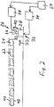
- Fig. 2 shows a schematic diagram of an electromechanical loading / unloading device 26.
- the loading / unloading device 26 has a first slide 28 which is translationally movable in the longitudinal direction of the support device 2, as in FIG Fig. 2 symbolized by a double arrow 30.
- the first carriage 28 is part of a first linear drive 32.
- the first The carriage 28 is in drive connection with a first electric motor 34 and carries an arm 33, the free end of which carries a pressure element 36 for loading and unloading the slats 22, 24.
- the pressure element 36 is designed as a wheel or roller.
- the pressure element 36 can be adjusted relative to a support plane defined by the slats 22, 24.
- An adjustment drive 38 is designed and arranged for adjusting the pressure element 36 relative to the support plane, as in FIG Fig. 2 symbolized by a double arrow 40.
- An associated adjustment drive 38 which has a second electric motor, is described below with reference to FIG Fig. 6 and Fig. 7 explained in more detail.
- the slats 22, 24 are held between flexible bands that are shown in Fig. 2 are symbolized by dashed lines 40, 42.
- the first carriage 28 of the first linear drive is moved along the associated linear axis in FIG Fig. 2 moved to the left.
- the pressure element 36 can be adjusted relative to the slats 22, 24 by means of the adjusting drive 38, in order to effect loading / unloading on them and thereby to realize a massage function.
- Fig. 3 shows the interaction between the pressure element 36 and the lath 24, wherein the pressure element 36 pressurizes the lath 24 so that it is deflected in such a way that it protrudes over the plane of support. How out Fig. 3 evident, that lies Pressure element 36 on the side of the belt 40 that faces away from the slats 22, 24.
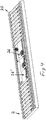
- Fig. 4 the support device 2 is shown, with some slats being omitted to illustrate details of the electromechanical loading / unloading device 26.
- a further loading / unloading device 26 ′ is provided in addition to the loading / unloading device 26.
- the loading / unloading devices 26, 26 ' are arranged at a distance from one another in the longitudinal direction of the support device 2 in order to enable a massage effect in different areas in the longitudinal direction of the support device 2.
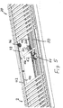
- Both loading / unloading devices 26, 26 ' have the same structure. Therefore, only the loading / unloading device 26 is explained in more detail below. For reasons of presentation, in FIGS. 4 to 7 only the loading / unloading device 26 is shown, while the loading / unloading device 26 'is omitted.
- the loading / unloading device 26 has the first slide 28, which is part of the first linear drive and is movable in the longitudinal direction of the support device 2 along a linear axis.
- the linear axis is defined by a first linear guide 44 which extends in the longitudinal direction of the support device 2.
- the first slide 28 is in drive connection with the first electric motor 34, the first slide 28 carrying the arm 33 (cf. Fig. 5 and Fig. 6 ), the free end of which carries the pressure element 36 for loading or unloading the slats 22, 24.
- the pressure element 36 is designed as a wheel or roller which is mounted rotatably relative to the arm 33 and rests on the side of the belt 40 facing away from the slats 22, 24. (see in particular Fig. 6 ).
- the first carriage 28 carries two arms, namely the arm 33 and a further arm 33 ', each of the arms 33, 33' carrying a pressure element 36 and 36 ', respectively.
- the pressure elements 36, 36 ' are spaced apart from one another transversely to the longitudinal direction of the support device 2, as shown in particular in FIG Fig. 6 evident.
- the pressure elements 36, 36 ' are adjustable relative to the support plane defined by the slats 22, 24, the adjustment drive 38 being provided to adjust the pressure elements 36, 36' relative to the support plane.
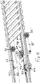
- a pivot shaft 46 is pivotably mounted on the first slide 28 (cf. Fig. 6 ), with which the arms 33, 33 'are rotatably connected.
- the adjustment drive 38 is designed to pivot the pivot shaft 46 about its pivot axis in order to adjust the pressure elements 36, 36 'relative to the slats 22, 24 by pivoting the arms 33, 33'. Accordingly, the arms 33, 33 'have the function of pivot levers.
- the first linear drive has a first spindle drive 48 (cf. Fig. 6 ) on.
- the first spindle drive 48 has a first threaded spindle, which extends in the longitudinal direction of the first linear guide 44 and is supported against rotation.
- a first spindle nut is placed on the first threaded spindle and is in rotary drive connection with the output shaft of the first electric motor 34 via a worm gear.
- the first spindle nut is received together with the worm gear and the output shaft in the first carriage 28, which is designed like a housing.
- the first spindle nut rotates.
- the first carriage 28 moves along the first linear guide 44 in one direction or the other corresponding to the direction of rotation of the spindle nut, whereby the first carriage 28 with the pressure elements 36, 36 'is positioned in the longitudinal direction of the first linear guide, so that slats at the corresponding point 22, 24 are acted upon by the pressure elements 36, 36 'for loading / relieving the relevant slats 22, 24.
- Running parallel to the first linear guide 44 is a second linear guide 50 (cf. Fig. 5 ) intended.
- a second slide 52 is guided on the second linear guide 50 in the longitudinal direction of the support device 2.
- the pivot shaft 46 is rotatably or pivotably connected to the second slide 52.
- the second slide 52 is thus connected to the first slide 28 in a non-displaceable manner by means of the pivot shaft. Accordingly, the carriages 28, 52 move synchronously when the first carriage 28 moves when the first electric motor 34 is actuated.
- the adjustment drive 38 has a second linear drive with a second electric motor 54 and a second spindle drive 56.
- a second spindle nut 58 is arranged on a second threaded spindle of the second spindle drive 56 so that it cannot rotate.
- the second spindle nut forms the output member of the second spindle drive 56.
- the second threaded spindle rotates so that the second spindle nut 58 moves in the axial direction of the second threaded spindle in one direction or the other corresponding to the direction of rotation of the second threaded spindle.
- a connecting bracket 60 is provided for rotating or pivoting the pivot shaft 46 about its pivot axis during a linear movement of the second spindle nut 58.
- a first end of the connecting plate 60 is articulated to the second spindle nut at a first hinge point 62, while a second end of the connecting plate 60 is connected to a second pivot point 64 is connected to the pivot shaft 46, specifically eccentrically to the pivot axis thereof, in such a way that the pivot shaft 46 pivots during a linear movement of the second spindle nut 58.
- a control device 64 (cf. Fig. 2 ) intended.
- the carriages 28, 52 are positioned relative to the slats 22, 24 along the linear guides 44, 50 in order to act on the slats 22, 24 in the respective area.
- the swivel shaft 46 swivels so that the pressure elements 36, 36 ′ act on the respective slats by applying pressure.
- the intensity of the resulting massage effect can be controlled by controlling the swivel angle.
Landscapes
- Health & Medical Sciences (AREA)
- General Health & Medical Sciences (AREA)
- Rehabilitation Therapy (AREA)
- Epidemiology (AREA)
- Pain & Pain Management (AREA)
- Physical Education & Sports Medicine (AREA)
- Nursing (AREA)
- Life Sciences & Earth Sciences (AREA)
- Animal Behavior & Ethology (AREA)
- Public Health (AREA)
- Veterinary Medicine (AREA)
- Massaging Devices (AREA)
- Invalid Beds And Related Equipment (AREA)
Abstract
Description
- Die Erfindung betrifft eine Stützeinrichtung der im Oberbegriff des Anspruchs 1 genannten Art.
- Derartige Stützeinrichtungen sind allgemein bekannt und können beispielsweise als Lattenrost ausgebildet sein. Die Stützeinrichtung weist einen Grundkörper auf, der vorzugsweise wenigstens zwei relativ zueinander verstellbare Stützteile aufweist, an denen Federelemente angeordnet sind, an denen sich bei Benutzung der Stützeinrichtung die Polsterung abstützt. Zur Verstellung der Stützteile relativ zueinander kann eine elektromotorische Verstelleinrichtung vorgesehen sein.
- Aus der
DE 10 2010 021 362 A1 ist eine Stützeinrichtung bekannt, bei der eine Be-/Entlastungseinrichtung zum Erzielen einer Druckbe- oder -entlastung an der Polsterung vorgesehen ist. Die Be-/Entlastungseinrichtung ist dabei unterhalb des Grundkörpers der Stützeinrichtung angeordnet. - Ähnliche Stützeinrichtungen sind auch durch
DE 10 2008 031 043 A1 ,DE 20 2005 009 180 U1 ,WO 2012/052972 A1 undDE 29509909 U1 bekannt. - Durch
WO 2016/156247 ist eine Stützeinrichtung der betreffenden Art zur Abstützung einer Polsterung eines Sitz- und/oder Liegemöbels bekannt, die einen Federelemente aufweisenden Grundkörper zur flächigen Abstützung der Polsterung und wenigstens eine Be-/Entlastungseinrichtung zum Erzielen einer Druckbe- und/oder Entlastung an der Polsterung aufweist, wobei die Be-/Entlastungeinrichtung zum Erzielen einer Druckbe-und/oder entlastung auf wenigstens ein Federelement einwirkt. Die Be-/Entlastungseinrichtung weist wenigstens einen Elektromotor auf, der in Wirkungsverbindung mit wenigstens einem Druckelement steht, mittels dessen zur Erzielung einer Druckbe- und/oder entlastung eine Drucckraft auf wenigstens ein Federelement ausübbar oder ausgeübt wird. - Der Erfindung liegt die Aufgabe zugrunde, eine Stützeinrichtung der im Oberbegriff des Anspruchs 1 angegebenen Art anzugeben, die einfach aufgebaut und robust ist.
- Diese Aufgabe wird durch die im Anspruch 1 angegebene Erfindung gelöst.
- Erfindungsgemäß weist die Be-/Entlastungseinrichtung wenigstens einen mit einem Elektromotor in Antriebsverbindung stehenden ersten Schlitten auf, der in Längsrichtung der Stützeinrichtung translatorisch beweglich ist, wobei der Schlitten wenigstens einen Arm trägt, dessen freien Ende das Druckelement trägt zum Be-/Entlasten der Federelemente.
- Erfindungsgemäß ist das Druckelement oder sind die Druckelemente an wenigstens einem Schlitten angeordnet, der in Längsrichtung der Stützeinrichtung translatorisch beweglich ist. Entsprechend der jeweiligen Position des Schlittens in Längsrichtung der Stützeinrichtung werden unterschiedliche Federelemente und damit unterschiedliche Bereiche in Längsrichtung der Stützeinrichtung druckbeaufschlagt, so dass beispielsweise eine Massagewirkung erzielt werden kann. Durch entsprechende Bewegung des Schlittens kann beispielsweise eine rollierende Massagewirkung erzielt werden, die in der Regel als angenehm empfunden wird.
- Die erfindungsgemäße Stützeinrichtung eröffnet damit vielfältige Möglichkeiten, beispielsweise zum Erzielen einer Massagewirkung.
- Grundsätzlich ist es ausreichend, wenn ein einzelnes Druckelement vorgesehen ist, das beispielsweise in der Längsmittelebene der Stützeinrichtung auf die Federelemente wirkt. Um eine quer zur Längsrichtung gleichmäßigere Druckeinwirkung zu erzielen, sieht eine vorteilhafte Weiterbildung der Erfindung vor, dass der erste Schlitten wenigstens zwei Arme trägt, die jeweils ein Druckelement tragen, wobei die Druckelemente relativ zueinander quer zur Längsrichtung der Stützeinrichtung zueinander beabstandet sind.
- Eine andere vorteilhafte Weiterbildung der Erfindung sieht vor, dass die Federelemente federnde Latten sind, die über wenigstens ein flexibles Band miteinander verbunden sind, wobei wenigstens ein Druckelement an dem Band anliegt zum Be- oder Entlasten der Latten über das Band. Auf diese Weise ergibt sich ein besonders einfacher Aufbau der Be-/Entlastungseinrichtung.
- Form und Ausgestaltung des Druckelementes sind entsprechend den jeweiligen Anforderungen innerhalb weiter Grenzen wählbar. Eine vorteilhafte Weiterbildung der Erfindung sieht vor, dass wenigstens ein Druckelement als Rad oder Rolle ausgebildet ist.
- Gemäß einer anderen vorteilhaften Weiterbildung der Erfindung ist dem ersten Schlitten ein erster elektromotorischer Linearantrieb zugeordnet zum Bewegen des Schlittens in Längsrichtung der Stützeinrichtung. Entsprechende Linearantriebe stehen als relativ einfache und kostengünstige Standardbauteile zur Verfügung.
- Eine außerordentlich vorteilhafte Weiterbildung der Erfindung sieht vor, dass das oder jedes Druckelement in Richtung auf die Unterstützungsebene und in Richtung weg von der Unterstützungsebene relativ zu den Federelementen verstellbar ist und dass dem oder jedem Druckelement ein elektromotorischer Verstellantrieb zugeordnet ist. Auf diese Weise lässt sich nicht nur die Position verstellen, an der eine Be- und Entlastung, beispielsweise zum Erzielen einer Massagewirkung, ausgeführt wird, sondern zusätzlich auch die Intensität der Druckbelastung, indem das Druckelement relativ zu der Unterstützungsebene mehr oder weniger stark verstellt wird. Dadurch lässt sich beispielsweise die Intensität einer Massagewirkung an die Gegebenheiten des jeweiligen Benutzers anpassen.
- Bei der vorgenannten Ausführungsform kann die Verstellung des Druckelementes relativ zu der Unterstützungsebene in vielfältiger Weise realisiert werden. Im Sinne eines besonders einfachen und robusten Aufbaus sieht eine vorteilhafte Weiterbildung vor, dass das oder jedes Druckelement an einem freien Ende eines Schwenkhebels angeordnet ist und dass zum Verstellen des Druckelementes relativ zu den Federelementen dem Schwenkhebel ein Schwenkantrieb als Verstellantrieb zugeordnet ist.
- Eine vorteilhafte Weiterbildung der vorgenannten Ausführungsform sieht vor, dass der oder jeder Schwenkantrieb einen zweiten elektromotorischen Linearantrieb aufweist.
- Eine Weiterbildung der Ausführungsformen mit den Linearantrieben sieht vor, dass wenigstens ein elektromotorischer Linearantrieb einen Spindeltrieb aufweist. Entsprechende Spindeltriebe stehen als relativ einfache und kostengünstige Standardbaugruppen zur Verfügung und sind besonders robust.
- Eine andere Weiterbildung der Ausführungsform mit dem Schwenkhebel oder den Schwenkhebeln sieht vor, dass der oder jeder Schwenkhebel drehfest mit einer schwenkbar an dem ersten Schlitten gelagerten Schwenkwelle verbunden ist, wobei die Schwenkwelle mit dem zweiten elektromotorischen Linearantrieb in Schwenkantriebsverbindung steht. Bei dieser Ausführungsform wirkt der Schwenkantrieb auf die Schwenkwelle.
- Bei Verwendung eines Linearantriebs als Schwenkantrieb kann die Umsetzung der Linearbewegung des Abtriebsorganes des Linearantriebs in eine Schwenkbewegung auf vielfältige Weise realisiert werden. Eine besonders einfach aufgebaute Ausführungsform sieht insoweit vor, dass ein erstes Ende einer Verbindungslasche an einem ersten Gelenkpunkt gelenkig mit einem linear beweglichen Abtriebsorgan des zweiten Linearantriebs verbunden ist, während ein zweites Ende der Verbindungslasche an einem zweiten Gelenkpunkt mit der Schwenkwelle exzentrisch zu deren Schwenkachse verbunden ist, derart, dass die Schwenkwelle bei einer Linearbewegung des Abtriebsorgans um ihre Schwenkachse verschwenkt.
- Erfindungsgemäß ist es grundsätzlich ausreichend, wenn die Stützeinrichtung eine einzelne Be-/Entlastungseinrichtung aufweist. Eine Be- bzw. Entlastung an unterschiedlichen Stellen der Stützeinrichtung lässt sich dann dadurch erzielen, dass der Schlitten entsprechend positioniert wird. Um gleichzeitig in wenigstens zwei in Längsrichtung der Stützeinrichtung zueinander beabstandeten Bereichen eine Be- bzw. Entlastung zu erzielen, sieht eine vorteilhafte Weiterbildung vor, dass wenigstens zwei Be-/Entlastungseinrichtungen vorgesehen sind, die in Längsrichtung der Stützeinrichtung zueinander beabstandet sind zum Beaufschlagen unterschiedlicher Bereiche in Längsrichtung der Stützeinrichtung. Auf diese Weise ist der Komfort für einen Benutzer der Stützeinrichtung weiter erhöht, indem beispielsweise gleichzeitig in unterschiedlichen Bereichen der Stützeinrichtung eine Massagewirkung erzielt werden kann.
- Eine andere vorteilhafte Weiterbildung sieht eine Steuerungseinrichtung zur Ansteuerung des Elektromotors oder der Elektromotoren vor. Die Betätigung der Steuerungseinrichtung kann beispielsweise über eine Fernbedienung oder einen Handschalter drahtgebunden oder drahtlos erfolgen.
- Eine außerordentlich vorteilhafte Weiterbildung der Erfindung sieht vor, dass die Steuerungseinrichtung den Elektromotor oder die Elektromotoren derart ansteuert, dass das Druckelement oder die Druckelemente zeitlich aufeinanderfolgend auf wenigstens zwei in Längsrichtung der Stützeinrichtung aufeinanderfolgende Federelemente einwirkt bzw. einwirken. Durch entsprechende Programmierung der Steuerungseinrichtung lassen sich damit nahezu beliebige Belastungs- bzw. Massageschemata realisieren.
- Im Sinne eines einfachen und unkomplizierten Aufbaus sieht eine andere vorteilhafte Weiterbildung der Erfindung vor, dass das oder jedes Druckelement das oder jedes zugeordnete Federelement lose beaufschlagt.
- Die Federelemente können beispielsweise als federnde Latten in vielfältiger Weise ausgebildet sein. Insoweit sieht eine andere vorteilhafte Weiterbildung vor, dass die Federelemente Federhölzer sind. Entsprechende Federhölzer stehen als einfache und kostengünstige Standardbauteile zur Verfügung und bieten einen hohen Federungskomfort.
- Erfindungsgemäß ist es grundsätzlich ausreichend, wenn der Grundkörper der Stützeinrichtung ein einzelnes, eine im Wesentlichen horizontale Stützebene definierendes Stützteil aufweist. Um den Komfort für einen Benutzer der Stützeinrichtung weiter zu erhöhen, sieht eine vorteilhafte Weiterbildung vor, dass die Stützeinrichtung wenigstens zwei relativ zueinander schwenkverstellbare Stützteile aufweist. Damit bietet die Stützeinrichtung Verstellmöglichkeiten, beispielsweise zwischen einer Sitzposition und einer Liegeposition, wie dies von Lattenrosten allgemein bekannt ist.
- Um den Komfort weiter zu erhöhen, sieht eine Weiterbildung der vorgenannten Ausführungsform wenigstens eine an der Stützeinrichtung angeordnete elektromotorische Verstelleinrichtung zur Verstellung wenigstens eines Stützteiles in seiner Neigung und/oder seiner Höhe vor.
- Eine andere vorteilhafte Weiterbildung der Erfindung sieht vor, dass die Be/Entlastungseinrichtung zusammen mit der Stützeinrichtung und der Polsterung in einer gemeinsamen Ummantelung aufgenommen ist.
- Gemäß einer anderen vorteilhaften Weiterbildung der Erfindung ist die Be-/Entlastungseinrichtung innerhalb der Profilhöhe des Grundkörpers der Stützeinrichtung angeordnet ist. Unter einer Anordnung innerhalb der Profilhöhe des Grundkörpers der Stützeinrichtung ist erfindungsgemäß zu verstehen, dass die Be-/Entlastungseinrichtung in der Seitenansicht, also in Vertikalrichtung, nicht über den Grundkörper übersteht.
- Eine andere außerordentlich vorteilhafte Weiterbildung der Erfindung sieht der Unterstützungsebene zugeordnete Sensormittel zum Abfühlen des Gewichts einer auf der Stützeinrichtung ruhenden Person vor, wobei die Sensormittel in Datenübertragungsverbindung mit der Steuerungseinrichtung stehen und die Steuerungseinrichtung derart ausgebildet und programmiert ist, dass die von wenigstens einem Druckelement ausgeübte Druckkraft in Abhängigkeit von dem abgefühlten Gewicht einstellbar ist oder eingestellt wird. Auf diese Weise kann bei einer Person mit einem relativ geringen Körpergewicht mit einer relativ geringen Druckkraft und bei einer Person mit einem relativ hohen Körpergewicht mit einer relativ großen Drucckraft belastet werden, so dass die Massagewirkung an das Körpergewicht des jeweiligen Benutzers angepasst wird. Auf diese Weise kann für Benutzer unterschiedlichen Körpergewichts eine jeweils als angenehm empfundene Massagefunktion realisiert werden.
- Die Erfindung wird nachfolgend unter Bezugnahme auf die beigefügte Zeichnung näher erläutert, in der ein Ausführungsbeispiel einer erfindungsgemäßen Stützeinrichtung dargestellt ist. Dabei bilden alle beschriebenen, in der Zeichnung dargestellten und in den Patentansprüchen beanspruchten Merkmale für sich genommen sowie in beliebiger geeigneter Kombination miteinander den Gegenstand der Erfindung, unabhängig von ihrer Beschreibung bzw. Darstellung in der Zeichnung sowie unabhängig von ihrer Zusammenfassung in den Patentansprüchen und deren Rückbezügen.
- Es zeigt:
- Fig. 1
- eine schematische Perspektivansicht eines Ausführungsbeispiels einer erfindungsgemäßen Stützeinrichtung,
- Fig. 2
- eine Prinzipskizze zur Erläuterung des Funktionsprinzips einer Be-/Entlastungseinrichtung der Stützeinrich-tung gemäß
Fig. 2 - Fig.3
- in gleicher Darstellung wie
Fig. 2 eine weitere Prinzipskizze, - Fig. 4
- die Stützeinrichtung gemäß
Fig. 1 , wobei aus Darstellungsgründen in einem Bereich der Stützeinrichtung Federelemente in Form von federnden Latten weggelassen sind, - Fig. 5
- in gleicher Darstellung wie
Fig. 4 , jedoch in vergrößertem Maßstab eine Einzelheit ausFig. 4 , wobei aus Darstellungsgründen wei-tere Bauteile der Stützeinrichtung wegge-lassen sind, - Fig. 6
- eine Perspektivansicht einer Be-/Entlastungseinrichtung der Stützeinrich-tung gemäß
Fig. 1 und - Fig.7
- eine weitere Perspektivansicht der Be-/Entlastungseinrichtung gemäß
Fig. 6 . - In
Fig. 1 ist ein Ausführungsbeispiel einer erfindungsgemäßen Stützeinrichtung 2 dargestellt, die einen Grundkörper 20 aufweist, der bei diesem Ausführungsbeispiel als Lattenrost ausgebildet ist und eine Mehrzahl von Federelementen aufweist, die durch federnde Latten gebildet sind. InFig. 1 sind lediglich zwei Latten mit den Bezugszeichen 22, 24 versehen. Die Oberseite der Latten 22, 24 definiert eine Unterstützungsebene, auf der sich bei Benutzung der Stützeinrichtung eine Polsterung, beispielsweise eine Matratze, abstützt. - Um eine Massagefunktion bereitzustellen, ist eine elektromechanische Be-/Entlastungseinrichtung vorgesehen, die nachfolgend näher erläutert wird.
-
Fig. 2 zeigt eine Prinzipskizze einer elektromechanischen Be-/Entlastungseinrichtung 26. - Die Be-/Entlastungseinrichtung 26 weist einen ersten Schlitten 28 auf, der translatorisch in Längsrichtung der Stützeinrichtung 2 beweglich ist, wie in
Fig. 2 durch einen Doppelpfeil 30 symbolisiert. Der erste Schlitten 28 ist Teil eines ersten Linearantriebs 32. Der erste Schlitten 28 steht in Antriebsverbindung mit einem ersten Elektromotor 34 und trägt einen Arm 33, dessen freies Ende ein Druckelement 36 zum Be- bzw. Entlasten der Latten 22, 24 trägt. - Das Druckelement 36 ist bei diesem Ausführungsbeispiel als Rad bzw. Rolle ausgebildet.
- Das Druckelement 36 ist relativ zu einer durch die Latten 22, 24 definierten Unterstützungsebene verstellbar. Ein Verstellantrieb 38 ist zur Verstellung des Druckelements 36 relativ zu der Unterstützungsebene ausgebildet und angeordnet, wie in
Fig. 2 durch einen Doppelpfeil 40 symbolisiert. Ein zugehöriger Verstellantrieb 38, der einen zweiten Elektromotor aufweist, wird weiter unten unter Bezugnahme aufFig. 6 undFig. 7 näher erläutert. - Die Latten 22, 24 sind zwischen flexiblen Bändern gehalten, die in
Fig. 2 durch gestrichelte Linien 40, 42 symbolisiert sind. - Bei Benutzung der Stützeinrichtung 2 wird zum Erzielen einer Massagewirkung der erste Schlitten 28 des ersten Linearantriebs entlang der zugeordneten linearen Achse in
Fig. 2 nach links bewegt. - Das Druckelement 36 ist mittels des Verstellantriebs 38 relativ den Latten 22, 24 verstellbar, um an denselben eine Be-/Entlastung zu bewirken und dadurch eine Massagefunktion zu realisieren.
-
Fig. 3 zeigt die Wechselwirkung zwischen dem Druckelement 36 und der Latte 24, wobei das Druckelement 36 die Latte 24 druckbeaufschlagt, so dass diese so ausgelenkt wird, dass sie über die Unterstützungsebene vorsteht. Wie ausFig. 3 ersichtlich, liegt das Druckelement 36 an der Seite des Bandes 40 an, die den Latten 22, 24 abgewandt ist. - Wie aus
Fig. 2 undFig. 3 ersichtlich ist, werden bei einer linearen Bewegung des ersten Schlittens 28 die in Längsrichtung der Stützeinrichtung 2 aufeinanderfolgenden Latten 22, 24 nacheinander beaufschlagt, um einen "rollierenden" Massageeffekt zu erzielen. - Ein Ausführungsbeispiel zur praktischen Umsetzung des in
Fig. 2 undFig. 3 veranschaulichten Grundprinzips wird nachfolgend unter Bezugnahme aufFig. 4 bis Fig. 7 näher erläutert. - In
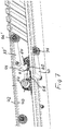
Fig. 4 ist die Stützeinrichtung 2 dargestellt, wobei zur Veranschaulichtung von Einzelheiten der elektromnechanischen Be-/Entlastungseinrichtung 26 einige Latten weggelassen sind. - Bei diesem Ausführungsbeispiel ist zusätzlich zu der Be-/Entlastungseinrichtung 26 eine weitere Be-/Entlastungseinrichtung 26' vorgesehen. Die Be-/Entlastungseinrichtungen 26, 26' sind in Längsrichtung der Stützeinrichtung 2 zueinander beabstandet angeordnet, um in Längsrichtung der Stützeinrichtung 2 in unterschiedlichen Bereichen eine Massagewirkung zu ermöglichen.
- Beide Be-/Entlastungseinrichtungen 26, 26' haben den gleichen Aufbau. Daher wird im Folgenden ausschließlich die Be-/Entlastungseinrichtung 26 näher erläutert. Aus Darstellungsgründen ist in
Fig. 4 bis Fig. 7 auschließlich die Be-/Entlastungseinrichtung 26 dargestellt, während die Be-/Entlastungseinrichtung 26' weggelassen ist. - Wie in
Fig. 5 dargestellt, weist die Be-/Entlastungseinrichtung 26 den ersten Schlitten 28 auf, der Teil des ersten Linearantriebs ist und in Längsrichtung der Stützeinrichtung 2 entlang einer linearen Achse beweglich ist. Die lineare Achse ist durch eine erste Linearführung 44 definiert, die sich in Längsrichtung der Stützeinrichtung 2 erstreckt. - Der erste Schlitten 28 steht in Antriebsverbindung mit dem ersten Elektromotor 34, wobei der erste Schlitten 28 den Arm 33 trägt (vgl.
Fig. 5 undFig. 6 ), dessen freies Ende das Druckelement 36 zum Belasten bzw. Entlasten der Latten 22, 24 trägt. Das Druckelement 36 ist bei diesem Ausführungsbeispiel als Rad bzw. Rolle ausgebildet, das bzw. die relativ zu dem Arm 33 drehbar gelagert ist und an der den Latten 22, 24 abgewandten Seite des Bandes 40 anliegt. (vgl. insbesondereFig. 6 ). - Bei dem dargestellten Ausführungsbeispiel trägt der erste Schlitten 28 zwei Arme, nämlich den Arm 33 sowie einen weiteren Arm 33', wobei jeder der Arme 33, 33' ein Druckelement 36 bzw. 36' trägt. Die Druckelemente 36, 36' sind relativ zueinander quer zur Längsrichtung der Stützeinrichtung 2 zueinander beabstandet, wie insbesondere aus
Fig. 6 ersichtlich. - Die Druckelemente 36, 36' sind relativ zu der durch die Latten 22, 24 definierten Unterstützungsebene verstellbar, wobei der Verstellantrieb 38 vorgesehen ist, um die Druckelemente 36, 36' relativ zu der Unterstützungsebene zu verstellen.
- An dem ersten Schlitten 28 ist eine Schwenkwelle 46 schwenkbar gelagert (vgl.
Fig. 6 ), mit der die Arme 33, 33' drehfest verbunden sind. Der Verstellantrieb 38 ist dazu ausgebildet, die Schwenkwelle 46 um ihre Schwenkachse zu verschwenken, um durch Verschwenken der Arme 33, 33' die Druckelemente 36, 36' relativ zu den Latten 22, 24 zu verstellen. Dementsprechend haben die Arme 33, 33' die Funktion von Schwenkhebeln. - Um den ersten Schlitten 28 entlang der ersten Linearführung 44 zu bewegen, weist der erste Linearantrieb einen ersten Spindeltrieb 48 (vgl.
Fig. 6 ) auf. Der erste Spindeltrieb 48 weist eine erste Gewindespindel auf, die sich in Längsrichtung der ersten Linearführung 44 erstreckt und verdrehsicher gelagert ist. Eine erste Spindelmutter ist auf die erste Gewindespindel aufgesetzt und steht über ein Schneckengetriebe in Drehantriebsverbindung mit der Abtriebswelle des ersten Elektromotors 34. Die erste Spindelmutter ist zusammen mit dem Schneckengetriebe und der Abtriebswelle in dem ersten Schlitten 28 aufgenommen, der gehäuseartig ausgebildet ist. - Bei Drehung der Abtriebswelle des ersten Elektromotors 34 dreht sich die erste Spindelmutter. Demzufolge bewegt sich der erste Schlitten 28 entlang der ersten Linearführung 44 in der einen oder anderen Richtung entsprechend dem Drehsinn der Spindelmutter, wodurch der erste Schlitten 28 mit den Druckelementen 36, 36' in Längsrichtung der ersten Linearführung positioniert wird, damit an der entsprechenden Stelle Latten 22, 24 durch die Druckelemente 36, 36' beaufschlagt werden zum Be-/Entlasten der betreffenden Latten 22, 24.
- Parallel zu der ersten Linearführung 44 verlaufend ist eine zweite Linearführung 50 (vgl.
Fig. 5 ) vorgesehen. An der zweiten Linearführung 50 ist ein zweiter Schlitten 52 in Längsrichtung der Stützeinrichtung 2 geführt. - Die Schwenkwelle 46 ist drehbar bzw. schwenkbar mit dem zweiten Schlitten 52 verbunden. Der zweite Schlitten 52 ist somit mittels der Schwenkwelle verschiebefest mit dem ersten Schlitten 28 verbunden. Dementsprechend bewegen sich die Schlitten 28, 52 synchron, wenn sich der erste Schlitten 28 bei Betätigung des ersten Elektromotors 34 bewegt.
- Unter Bezugnahme auf
Fig. 7 wird nachfolgend der Verstellantrieb 38 näher erläutert. - Der Verstellantrieb 38 weist einen zweiten Linearantrieb mit einem zweiten Elektromotor 54 und einem zweiten Spindeltrieb 56 auf.
- Auf einer zweiten Gewindespindel des zweiten Spindeltriebs 56 ist verdrehsicher eine zweite Spindelmutter 58 angeordnet. Die zweite Spindelmutter bildet das Abtriebsorgan des zweiten Spindeltriebs 56. Bei Betätigung des zweiten Elektromotors 54 dreht sich die zweite Gewindespindel, so dass sich die zweite Spindelmutter 58 in Axialrichtung der zweiten Gewindespindel in der einen oder anderen Richtung bewegt entsprechend dem Drehsinn der zweiten Gewindespindel.
- Wie in
Fig. 7 dargestellt, ist zum Verdrehen bzw. Verschwenken der Schwenkwelle 46 um ihre Schwenkachse bei einer Linearbewegung der zweiten Spindelmutter 58 eine Verbindungslasche 60 vorgesehen. Ein erstes Ende der Verbindungslasche 60 ist an einem ersten Gelenkpunkt 62 gelenkig mit der zweiten Spindelmutter verbunden, während ein zweites Ende der Verbindungslasche 60 an einem zweiten Gelenkpunkt 64 mit der Schwenkwelle 46 verbunden ist, und zwar exzentrisch zu deren Schwenkachse, derart, dass die Schwenkwelle 46 bei einer Linearbewegung der zweiten Spindelmutter 58 verschwenkt. - Zur Ansteuerung der Elektromotoren 34, 54 ist eine Steuerungseinrichtung 64 (vgl.
Fig. 2 ) vorgesehen. - Bei Betätigung des ersten Elektromotors 34 werden die Schlitten 28, 52 relativ zu den Latten 22, 24 entlang der Linearführungen 44, 50 positioniert, um die Latten 22, 24 in dem jeweiligen Bereich zu beaufschlagen.
- Bei Betätigung des zweiten Elektromotors 54 verschwenkt die Schwenkwelle 46, so dass die Druckelemente 36, 36' die jeweiligen Latten durch Druckbelastung beaufschlagen. Die Intensität des resultierenden Massageeffekts ist durch Steuerung des Schwenkwinkels steuerbar.
Claims (14)
- Stützeinrichtung (2) zur Abstützung einer Polsterung eines Sitz- und/oder Liegemöbels, insbesondere einer Matratze eines Bettes,
mit einem Federelemente (22, 24) aufweisenden Grundkörper (20) zur flächigen Abstützung der Polsterung und
mit wenigstens einer Be-/Entlastungseinrichtung (8) zum Erzielen einer Druckbe- oder -entlastung an der Polsterung, wobei die Be-/Entlastungseinrichtung (8) zum Erzielen einer Druckbe- oder -entlastung auf wenigstens ein Federelement (22, 24) einwirkt,
wobei die Be-/Entlastungseinrichtung wenigstens einen Elektromotor (34) aufweist, der in Wirkungsverbindung mit wenigstens einem Druckelement (36) steht, mittels dessen zur Erzielung einer Druckbe- oder -entlastung eine Drucckraft auf wenigstens ein Federelement (22, 24) ausübbar ist oder ausgeübt wird und
wobei die Be-/Entlastungseinrichtung (8) wenigstens einen mit einem Elektromotor (34) in Antriebsverbindung stehenden ersten Schlitten (28) aufweist, der in Längsrichtung der Stützeinrichtung (2) translatorisch beweglich ist, wobei der erste Schlitten (28) wenigstens einen Arm (33) trägt, dessen freies Ende das Druckelement (36) trägt zum Be-/Entlasten der Federelemente (22, 24)
dadurch gekennzeichnet,
dass die Be-/Entlastungseinrichtung (26, 26') innerhalb der Profilhöhe des Grundkörpers (20) der Stützeinrichtung (2) angeordnet ist. - Stützeinrichtung nach Anspruch 1 oder dem Oberbegriff des Anspruchs 1, dadurch gekennzeichnet, dass der erste Schlitten (28) wenigstens zwei Arme (33, 33') trägt, die jeweils ein Druckelement (36, 36') tragen, wobei die Druckelemente (36, 36') quer zur Längsrichtung der Stützeinrichtung (2) beabstandet sind.
- Stützeinrichtung nach Anspruch 1 oder 2, dadurch gekennzeichnet, dass die Federelemente federnde Latten (22, 24) sind, die über wenigstens ein flexibles Band (40, 42) miteinander verbunden sind, wobei wenigstens ein Druckelement (36, 36' an dem Band (40) anliegt zum Be-/Entlasten der Latten (22, 24) über das Band (40).
- Stützeinrichtung nach einem der vorhergehenden Ansprüche, dadurch gekennzeichnet, dass wenigstens ein Druckelement (36, 36') als Rad oder Rolle ausgebildet ist und/oder dass das oder jedes Druckelement (36, 36') in Richtung auf die Unterstützungsebene und in Richtung weg von der Unterstützungsebene relativ zu den Federelementen (22, 24) verstellbar ist, wobei dem oder jedem Druckelement (36, 36') ein elektromotorischer Verstellantrieb zugeordnet ist, und/oder dass das oder jedes Druckelement (36, 36') an einem freien Ende eines Schwenkhebels angeordnet ist, wobei zum Verstellen des Druckelements (36, 36') relativ zu den Federelementen (22, 24) dem Schwenkhebel ein Schwenkantrieb als Verstellantrieb zugeordnet ist.
- Stützeinrichtung nach einem der vorhergehenden Ansprüche, dadurch gekennzeichnet, dass dem ersten Schlitten (28) ein erster elektromotorischer Linearantrieb zugeordnet ist zum Bewegen des ersten Schlittens (28) in Längsrichtung der Stützeinrichtung (2).
- Stützeinrichtung nach Anspruch 5, dadurch gekennzeichnet, dass der oder jeder Schwenkantrieb einen zweiten elektromotorischen Linearantrieb aufweist.
- Stützeinrichtung nach einem der vorhergehenden Ansprüche, dadurch gekennzeichnet, dass wenigstens ein elektromotorischer Linearantrieb einen Spindeltrieb aufweist.
- Stützeinrichtung nach einem der Ansprüche 5 bis 7, dadurch gekennzeichnet, dass der oder jeder Schwenkhebel drehfest mit einer schwenkbar an dem ersten Schlitten gelagerten Schwenkwelle (46) verbunden ist, wobei die Schwenkwelle (46) mit dem zweiten elektromotorischen Linearantrieb in Schwenkantriebsverbindung steht.
- Stützeinrichtung nach einem der Ansprüche 5 bis 8, dadurch gekennzeichnet, dass ein erstes Ende einer Verbindungslasche (60) an einem ersten Gelenkpunkt (62) gelenkig mit einem linear beweglichen Abtriebsorgan des zweiten Linearantriebs verbunden ist, während ein zweites Ende der Verbindungslasche (60) an einem zweiten Gelenkpunkt (64) mit der Schwenkwelle (46) exzentrisch zu deren Schwenkachse verbunden ist, derart, dass die Schwenkwelle (46) bei einer Linearbewegung des Abtriebsorganes um ihre Schwenkachse verschwenkt.
- Stützeinrichtung nach einem der vorhergehenden Ansprüche, dadurch gekennzeichnet, dass wenigstens zwei Be-/Entlastungseinrichtungen (26, 26') vorgesehen sind, die in Längsrichtung der Stützeinrichtung (2) zueinander beabstandet sind zum Beaufschlagen unterschiedlicher Bereiche in Längsrichtung der Stützeinrichtung (2).
- Stützeinrichtung nach einem der vorhergehenden Ansprüche, gekennzeichnet durch eine Steuerungseinrichtung (64) zur Ansteuerung des Elektromotors oder der Elektromotoren (34, 54), wobei vorzugsweise die Steuerungseinrichtung (64) den Elektromotor oder die Elektromotoren (34, 54) derart ansteuert, dass das Druckelement oder die Druckelemente (36, 36') zeitlich aufeinanderfolgend auf wenigstens zwei in Längsrichtung der Stützeinrichtung (2) aufeinanderfolgende Federelemente (22, 24) einwirkt bzw. einwirken.
- Stützeinrichtung nach einem der vorhergehenden Ansprüche, dadurch gekennzeichnet, dass das oder jedes Druckelement (36, 36') das oder jedes zugeordnete Federelement (22, 24) lose beaufschlagt und/ oder dass die Federelemente (22, 24) Federhölzer sind und/oder dass die Stützeinrichtung (2) wenigstens zwei relativ zueinander schwenkverstellbare Stützteile aufweist, wobei die Stützeinrichtung vorzugsweise wenigstens eine an der Stützeinrichtung (2) angeordnete elektromotorische Verstelleinrichtung zur Verstellung wenigstens eines Stützteiles in seiner Neigung und/oder seiner Höhe aufweist.
- Stützeinrichtung nach einem der vorhergehenden Ansprüche, dadurch gekennzeichnet, dass die Be-/Entlastungseinrichtung (26, 26') zusammen mit der Stützeinrichtung (2) und der Polsterung in einer gemeinsamen Ummantelung aufgenommen ist.
- Stützeinrichtung nach einem der vorhergehenden Ansprüche, gekennzeichnet durch der Unterstützungsebene zugeordnete Sensormittel zum Abfühlen des Gewichtes einer auf der Stützeinrichtung (2) ruhenden Person, wobei die Sensormittel in Datenübertragungsverbindung mit der Steuerungseinrichtung (64) stehen und die Steuerungseinrichtung (64) derart ausgebildet und programmiert ist, dass die von wenigstens einem Druckelement (36, 36') ausgeübte Druckkraft in Abhängigkeit von dem abgefühlten Gewicht einstellbar ist oder eingestellt wird.
Applications Claiming Priority (3)
| Application Number | Priority Date | Filing Date | Title |
|---|---|---|---|
| DE102017122499 | 2017-09-27 | ||
| DE102017126092.7A DE102017126092A1 (de) | 2017-09-27 | 2017-11-08 | Stützeinrichtung |
| EP18187043.7A EP3461372B1 (de) | 2017-09-27 | 2018-08-02 | Polsterungseinrichtung |
Related Parent Applications (2)
| Application Number | Title | Priority Date | Filing Date |
|---|---|---|---|
| EP18187043.7A Division EP3461372B1 (de) | 2017-09-27 | 2018-08-02 | Polsterungseinrichtung |
| EP18187043.7A Division-Into EP3461372B1 (de) | 2017-09-27 | 2018-08-02 | Polsterungseinrichtung |
Publications (2)
| Publication Number | Publication Date |
|---|---|
| EP3704993A1 true EP3704993A1 (de) | 2020-09-09 |
| EP3704993B1 EP3704993B1 (de) | 2022-12-28 |
Family
ID=63143061
Family Applications (2)
| Application Number | Title | Priority Date | Filing Date |
|---|---|---|---|
| EP18187043.7A Not-in-force EP3461372B1 (de) | 2017-09-27 | 2018-08-02 | Polsterungseinrichtung |
| EP20165962.0A Active EP3704993B1 (de) | 2017-09-27 | 2018-08-02 | Stützeinrichtung |
Family Applications Before (1)
| Application Number | Title | Priority Date | Filing Date |
|---|---|---|---|
| EP18187043.7A Not-in-force EP3461372B1 (de) | 2017-09-27 | 2018-08-02 | Polsterungseinrichtung |
Country Status (2)
| Country | Link |
|---|---|
| EP (2) | EP3461372B1 (de) |
| CN (1) | CN109549396B (de) |
Citations (8)
| Publication number | Priority date | Publication date | Assignee | Title |
|---|---|---|---|---|
| DE29509909U1 (de) | 1995-06-19 | 1995-10-19 | Neumann, Wolfgang N., 82335 Berg | Bettlattenrost mit Kompensationsfederung |
| DE202005009180U1 (de) | 2005-06-10 | 2005-09-01 | Rössle & Wanner GmbH | Lattenrost |
| DE102008031043A1 (de) | 2008-06-24 | 2009-12-31 | Winter, Gerhard, Dipl.-Ing. | Vorrichtung für Lattenrostmatratzen |
| DE102010021362A1 (de) | 2010-05-25 | 2012-02-09 | Clemens Winter | Bewegungsmodul für einen Lattenrost, insbesondere Lattenrostmatratze |
| WO2012052972A1 (en) | 2010-10-21 | 2012-04-26 | Immo Matralat | Motorised bed base, slat module and bed |
| DE102012018068A1 (de) * | 2012-09-13 | 2014-03-13 | Anton Immel | Massagebett |
| DE202016001946U1 (de) * | 2015-03-26 | 2016-06-02 | Vdd Trading & Invest N.V. | Untergestell für ein Boxspring oder Komfortbett und mit derartigem Untergestell ausgerüstetes Boxspring oder Komfortbett |
| WO2016156247A1 (de) | 2015-03-31 | 2016-10-06 | Octo Group Ag | Verstellbare polsterungseinrichtung |
Family Cites Families (15)
| Publication number | Priority date | Publication date | Assignee | Title |
|---|---|---|---|---|
| US3628528A (en) * | 1970-05-21 | 1971-12-21 | Roll A Matic Inc | Massaging and reducing machine |
| DE19930928A1 (de) * | 1999-07-06 | 2001-01-18 | Elero Gmbh | Antrieb zum Verstellen des Kopf- und des Fußteiles eines Lattenrostes |
| DE50013095D1 (de) * | 1999-12-23 | 2006-08-10 | Cimosys Ag | Motorisch verstellbare stützeinrichtung für eine polsterung eines sitz- und/oder liegemöbels |
| JP2003070860A (ja) * | 2001-09-05 | 2003-03-11 | Atex:Kk | マッサージ機 |
| DE202004007549U1 (de) * | 2004-05-07 | 2004-09-09 | Dewert Antriebs- Und Systemtechnik Gmbh & Co. Kg | Möbel |
| DE102007041777A1 (de) * | 2007-09-04 | 2009-03-05 | Linrot Holding Ag | Elektromotorischer Möbelantrieb |
| US20100030121A1 (en) * | 2008-07-30 | 2010-02-04 | Wei Fu | Massage Chair Servo |
| CN102697325A (zh) * | 2012-04-13 | 2012-10-03 | 丁蕊 | 智能电动床 |
| CN203001397U (zh) * | 2012-11-16 | 2013-06-19 | 杨海春 | 一种脊柱按摩床 |
| EP2938312A4 (de) * | 2012-12-28 | 2016-08-31 | Tempur Pedic Man Llc | Massagekissenanordnungen |
| CN103330633A (zh) * | 2013-06-28 | 2013-10-02 | 无锡麻德克斯精机有限公司 | 按摩椅的升降按摩装置 |
| CN104188784B (zh) * | 2014-09-05 | 2016-04-13 | 常州工学院 | 一种床用按摩装置 |
| EP3206537A1 (de) * | 2014-10-16 | 2017-08-23 | De Werth Group AG | Elektromotorisch verstellbare stützeinrichtung |
| DE102015100703A1 (de) * | 2015-01-19 | 2016-07-21 | Sino-Europe GmbH & Co. KG | Lattenrost |
| DE102016116250A1 (de) * | 2016-04-29 | 2017-11-02 | De Werth Group Ag | Elektromotorischer Doppelantrieb |
-
2018
- 2018-08-02 EP EP18187043.7A patent/EP3461372B1/de not_active Not-in-force
- 2018-08-02 EP EP20165962.0A patent/EP3704993B1/de active Active
- 2018-09-21 CN CN201811104603.0A patent/CN109549396B/zh active Active
Patent Citations (8)
| Publication number | Priority date | Publication date | Assignee | Title |
|---|---|---|---|---|
| DE29509909U1 (de) | 1995-06-19 | 1995-10-19 | Neumann, Wolfgang N., 82335 Berg | Bettlattenrost mit Kompensationsfederung |
| DE202005009180U1 (de) | 2005-06-10 | 2005-09-01 | Rössle & Wanner GmbH | Lattenrost |
| DE102008031043A1 (de) | 2008-06-24 | 2009-12-31 | Winter, Gerhard, Dipl.-Ing. | Vorrichtung für Lattenrostmatratzen |
| DE102010021362A1 (de) | 2010-05-25 | 2012-02-09 | Clemens Winter | Bewegungsmodul für einen Lattenrost, insbesondere Lattenrostmatratze |
| WO2012052972A1 (en) | 2010-10-21 | 2012-04-26 | Immo Matralat | Motorised bed base, slat module and bed |
| DE102012018068A1 (de) * | 2012-09-13 | 2014-03-13 | Anton Immel | Massagebett |
| DE202016001946U1 (de) * | 2015-03-26 | 2016-06-02 | Vdd Trading & Invest N.V. | Untergestell für ein Boxspring oder Komfortbett und mit derartigem Untergestell ausgerüstetes Boxspring oder Komfortbett |
| WO2016156247A1 (de) | 2015-03-31 | 2016-10-06 | Octo Group Ag | Verstellbare polsterungseinrichtung |
Also Published As
| Publication number | Publication date |
|---|---|
| EP3704993B1 (de) | 2022-12-28 |
| CN109549396A (zh) | 2019-04-02 |
| EP3461372B1 (de) | 2020-10-07 |
| EP3461372A1 (de) | 2019-04-03 |
| CN109549396B (zh) | 2022-03-11 |
Similar Documents
| Publication | Publication Date | Title |
|---|---|---|
| EP1410743B1 (de) | Motorisch verstellbare Stützeinrichtung für eine Polsterung eines Sitz- und/oder Liegemöbels, beispielsweise einer Matratze oder eines Bettes | |
| EP1276406B1 (de) | Motorisch verstellbare stützeinrichtung für eine polsterung eines sitz- und/oder liegemöbels | |
| DE20308887U1 (de) | Motorisch verstellbare Stützeinrichtung für eine Polsterung eines Sitz- und/oder Liegemöbels | |
| EP3009051B1 (de) | Elektromotorisch verstellbare stützeinrichtung | |
| DE102009017894B4 (de) | Elektromotorisch verstellbare Stützeinrichtung | |
| DE10017979A1 (de) | Als Doppelantrieb ausgebildeter Möbelantrieb | |
| EP3291707B1 (de) | Elektromotorisch verstellbare stützeinrichtung | |
| DE102016116253A1 (de) | Elektromotorischer Doppelantrieb | |
| WO2002000065A1 (de) | Möbelantrieb zum verstellen von teilen eines möbels relativ zueinander | |
| DE10301326A1 (de) | Sitzmöbel, insbesondere Sessel | |
| EP1708595B1 (de) | Möbelantrieb zum verstellen eines ersten teiles eines möbels relativ zu einem zweiten teil | |
| DE102016116251A1 (de) | Elektromotorischer Doppelantrieb | |
| EP1416832B2 (de) | Möbelantrieb zum verstellen von teilen eines möbels relativ zueinander | |
| DE102017126092A1 (de) | Stützeinrichtung | |
| EP3954255B1 (de) | Elektromotorisch verstellbare stützeinrichtung | |
| DE202004018913U1 (de) | Baukastensystem zur Montage motorisch verstellbarer Stützeinrichtungen für Polsterungen von Sitz- und/oder Liegemöbeln | |
| EP4434405B1 (de) | Elektromotorisch verstellbare stützeinrichtung | |
| EP3461372B1 (de) | Polsterungseinrichtung | |
| EP1613195B1 (de) | Verstellbare liege oder bett | |
| DE102020131204A1 (de) | Elektromotorisch verstellbare Stützeinrichtung | |
| EP3238573B1 (de) | Elektromotorischer doppelantrieb | |
| DE102022111839A1 (de) | Elektromotorisch verstellbare Stützeinrichtung | |
| DE29909342U1 (de) | Verstellbare Vorrichtung zur Polsterunterstützung | |
| DE102023117637B4 (de) | Bett, Möbel und elektromotorisch verstellbare Stützeinrichtung | |
| DE102017122602A1 (de) | Kopfstütze für ein Polstermöbel |
Legal Events
| Date | Code | Title | Description |
|---|---|---|---|
| PUAI | Public reference made under article 153(3) epc to a published international application that has entered the european phase |
Free format text: ORIGINAL CODE: 0009012 |
|
| STAA | Information on the status of an ep patent application or granted ep patent |
Free format text: STATUS: THE APPLICATION HAS BEEN PUBLISHED |
|
| AC | Divisional application: reference to earlier application |
Ref document number: 3461372 Country of ref document: EP Kind code of ref document: P |
|
| AK | Designated contracting states |
Kind code of ref document: A1 Designated state(s): AL AT BE BG CH CY CZ DE DK EE ES FI FR GB GR HR HU IE IS IT LI LT LU LV MC MK MT NL NO PL PT RO RS SE SI SK SM TR |
|
| STAA | Information on the status of an ep patent application or granted ep patent |
Free format text: STATUS: REQUEST FOR EXAMINATION WAS MADE |
|
| 17P | Request for examination filed |
Effective date: 20210309 |
|
| RBV | Designated contracting states (corrected) |
Designated state(s): AL AT BE BG CH CY CZ DE DK EE ES FI FR GB GR HR HU IE IS IT LI LT LU LV MC MK MT NL NO PL PT RO RS SE SI SK SM TR |
|
| GRAP | Despatch of communication of intention to grant a patent |
Free format text: ORIGINAL CODE: EPIDOSNIGR1 |
|
| STAA | Information on the status of an ep patent application or granted ep patent |
Free format text: STATUS: GRANT OF PATENT IS INTENDED |
|
| INTG | Intention to grant announced |
Effective date: 20220912 |
|
| GRAS | Grant fee paid |
Free format text: ORIGINAL CODE: EPIDOSNIGR3 |
|
| GRAA | (expected) grant |
Free format text: ORIGINAL CODE: 0009210 |
|
| STAA | Information on the status of an ep patent application or granted ep patent |
Free format text: STATUS: THE PATENT HAS BEEN GRANTED |
|
| AC | Divisional application: reference to earlier application |
Ref document number: 3461372 Country of ref document: EP Kind code of ref document: P |
|
| AK | Designated contracting states |
Kind code of ref document: B1 Designated state(s): AL AT BE BG CH CY CZ DE DK EE ES FI FR GB GR HR HU IE IS IT LI LT LU LV MC MK MT NL NO PL PT RO RS SE SI SK SM TR |
|
| REG | Reference to a national code |
Ref country code: GB Ref legal event code: FG4D Free format text: NOT ENGLISH |
|
| REG | Reference to a national code |
Ref country code: CH Ref legal event code: EP |
|
| REG | Reference to a national code |
Ref country code: DE Ref legal event code: R096 Ref document number: 502018011343 Country of ref document: DE |
|
| REG | Reference to a national code |
Ref country code: AT Ref legal event code: REF Ref document number: 1539897 Country of ref document: AT Kind code of ref document: T Effective date: 20230115 |
|
| REG | Reference to a national code |
Ref country code: IE Ref legal event code: FG4D Free format text: LANGUAGE OF EP DOCUMENT: GERMAN |
|
| REG | Reference to a national code |
Ref country code: LT Ref legal event code: MG9D |
|
| PG25 | Lapsed in a contracting state [announced via postgrant information from national office to epo] |
Ref country code: SE Free format text: LAPSE BECAUSE OF FAILURE TO SUBMIT A TRANSLATION OF THE DESCRIPTION OR TO PAY THE FEE WITHIN THE PRESCRIBED TIME-LIMIT Effective date: 20221228 Ref country code: NO Free format text: LAPSE BECAUSE OF FAILURE TO SUBMIT A TRANSLATION OF THE DESCRIPTION OR TO PAY THE FEE WITHIN THE PRESCRIBED TIME-LIMIT Effective date: 20230328 Ref country code: LT Free format text: LAPSE BECAUSE OF FAILURE TO SUBMIT A TRANSLATION OF THE DESCRIPTION OR TO PAY THE FEE WITHIN THE PRESCRIBED TIME-LIMIT Effective date: 20221228 Ref country code: FI Free format text: LAPSE BECAUSE OF FAILURE TO SUBMIT A TRANSLATION OF THE DESCRIPTION OR TO PAY THE FEE WITHIN THE PRESCRIBED TIME-LIMIT Effective date: 20221228 |
|
| REG | Reference to a national code |
Ref country code: NL Ref legal event code: MP Effective date: 20221228 |
|
| PG25 | Lapsed in a contracting state [announced via postgrant information from national office to epo] |
Ref country code: RS Free format text: LAPSE BECAUSE OF FAILURE TO SUBMIT A TRANSLATION OF THE DESCRIPTION OR TO PAY THE FEE WITHIN THE PRESCRIBED TIME-LIMIT Effective date: 20221228 Ref country code: LV Free format text: LAPSE BECAUSE OF FAILURE TO SUBMIT A TRANSLATION OF THE DESCRIPTION OR TO PAY THE FEE WITHIN THE PRESCRIBED TIME-LIMIT Effective date: 20221228 Ref country code: HR Free format text: LAPSE BECAUSE OF FAILURE TO SUBMIT A TRANSLATION OF THE DESCRIPTION OR TO PAY THE FEE WITHIN THE PRESCRIBED TIME-LIMIT Effective date: 20221228 Ref country code: GR Free format text: LAPSE BECAUSE OF FAILURE TO SUBMIT A TRANSLATION OF THE DESCRIPTION OR TO PAY THE FEE WITHIN THE PRESCRIBED TIME-LIMIT Effective date: 20230329 |
|
| PG25 | Lapsed in a contracting state [announced via postgrant information from national office to epo] |
Ref country code: NL Free format text: LAPSE BECAUSE OF FAILURE TO SUBMIT A TRANSLATION OF THE DESCRIPTION OR TO PAY THE FEE WITHIN THE PRESCRIBED TIME-LIMIT Effective date: 20221228 |
|
| PG25 | Lapsed in a contracting state [announced via postgrant information from national office to epo] |
Ref country code: SM Free format text: LAPSE BECAUSE OF FAILURE TO SUBMIT A TRANSLATION OF THE DESCRIPTION OR TO PAY THE FEE WITHIN THE PRESCRIBED TIME-LIMIT Effective date: 20221228 Ref country code: RO Free format text: LAPSE BECAUSE OF FAILURE TO SUBMIT A TRANSLATION OF THE DESCRIPTION OR TO PAY THE FEE WITHIN THE PRESCRIBED TIME-LIMIT Effective date: 20221228 Ref country code: PT Free format text: LAPSE BECAUSE OF FAILURE TO SUBMIT A TRANSLATION OF THE DESCRIPTION OR TO PAY THE FEE WITHIN THE PRESCRIBED TIME-LIMIT Effective date: 20230428 Ref country code: ES Free format text: LAPSE BECAUSE OF FAILURE TO SUBMIT A TRANSLATION OF THE DESCRIPTION OR TO PAY THE FEE WITHIN THE PRESCRIBED TIME-LIMIT Effective date: 20221228 Ref country code: EE Free format text: LAPSE BECAUSE OF FAILURE TO SUBMIT A TRANSLATION OF THE DESCRIPTION OR TO PAY THE FEE WITHIN THE PRESCRIBED TIME-LIMIT Effective date: 20221228 Ref country code: CZ Free format text: LAPSE BECAUSE OF FAILURE TO SUBMIT A TRANSLATION OF THE DESCRIPTION OR TO PAY THE FEE WITHIN THE PRESCRIBED TIME-LIMIT Effective date: 20221228 |
|
| PG25 | Lapsed in a contracting state [announced via postgrant information from national office to epo] |
Ref country code: SK Free format text: LAPSE BECAUSE OF FAILURE TO SUBMIT A TRANSLATION OF THE DESCRIPTION OR TO PAY THE FEE WITHIN THE PRESCRIBED TIME-LIMIT Effective date: 20221228 Ref country code: PL Free format text: LAPSE BECAUSE OF FAILURE TO SUBMIT A TRANSLATION OF THE DESCRIPTION OR TO PAY THE FEE WITHIN THE PRESCRIBED TIME-LIMIT Effective date: 20221228 Ref country code: IS Free format text: LAPSE BECAUSE OF FAILURE TO SUBMIT A TRANSLATION OF THE DESCRIPTION OR TO PAY THE FEE WITHIN THE PRESCRIBED TIME-LIMIT Effective date: 20230428 Ref country code: AL Free format text: LAPSE BECAUSE OF FAILURE TO SUBMIT A TRANSLATION OF THE DESCRIPTION OR TO PAY THE FEE WITHIN THE PRESCRIBED TIME-LIMIT Effective date: 20221228 |
|
| REG | Reference to a national code |
Ref country code: DE Ref legal event code: R097 Ref document number: 502018011343 Country of ref document: DE |
|
| PG25 | Lapsed in a contracting state [announced via postgrant information from national office to epo] |
Ref country code: DK Free format text: LAPSE BECAUSE OF FAILURE TO SUBMIT A TRANSLATION OF THE DESCRIPTION OR TO PAY THE FEE WITHIN THE PRESCRIBED TIME-LIMIT Effective date: 20221228 |
|
| PLBE | No opposition filed within time limit |
Free format text: ORIGINAL CODE: 0009261 |
|
| STAA | Information on the status of an ep patent application or granted ep patent |
Free format text: STATUS: NO OPPOSITION FILED WITHIN TIME LIMIT |
|
| 26N | No opposition filed |
Effective date: 20230929 |
|
| PG25 | Lapsed in a contracting state [announced via postgrant information from national office to epo] |
Ref country code: SI Free format text: LAPSE BECAUSE OF FAILURE TO SUBMIT A TRANSLATION OF THE DESCRIPTION OR TO PAY THE FEE WITHIN THE PRESCRIBED TIME-LIMIT Effective date: 20221228 |
|
| PG25 | Lapsed in a contracting state [announced via postgrant information from national office to epo] |
Ref country code: MC Free format text: LAPSE BECAUSE OF FAILURE TO SUBMIT A TRANSLATION OF THE DESCRIPTION OR TO PAY THE FEE WITHIN THE PRESCRIBED TIME-LIMIT Effective date: 20221228 |
|
| REG | Reference to a national code |
Ref country code: CH Ref legal event code: PL |
|
| PG25 | Lapsed in a contracting state [announced via postgrant information from national office to epo] |
Ref country code: MC Free format text: LAPSE BECAUSE OF FAILURE TO SUBMIT A TRANSLATION OF THE DESCRIPTION OR TO PAY THE FEE WITHIN THE PRESCRIBED TIME-LIMIT Effective date: 20221228 |
|
| PG25 | Lapsed in a contracting state [announced via postgrant information from national office to epo] |
Ref country code: LU Free format text: LAPSE BECAUSE OF NON-PAYMENT OF DUE FEES Effective date: 20230802 |
|
| GBPC | Gb: european patent ceased through non-payment of renewal fee |
Effective date: 20230802 |
|
| PG25 | Lapsed in a contracting state [announced via postgrant information from national office to epo] |
Ref country code: LU Free format text: LAPSE BECAUSE OF NON-PAYMENT OF DUE FEES Effective date: 20230802 Ref country code: CH Free format text: LAPSE BECAUSE OF NON-PAYMENT OF DUE FEES Effective date: 20230831 |
|
| REG | Reference to a national code |
Ref country code: BE Ref legal event code: MM Effective date: 20230831 |
|
| REG | Reference to a national code |
Ref country code: IE Ref legal event code: MM4A |
|
| PG25 | Lapsed in a contracting state [announced via postgrant information from national office to epo] |
Ref country code: IT Free format text: LAPSE BECAUSE OF FAILURE TO SUBMIT A TRANSLATION OF THE DESCRIPTION OR TO PAY THE FEE WITHIN THE PRESCRIBED TIME-LIMIT Effective date: 20221228 |
|
| PG25 | Lapsed in a contracting state [announced via postgrant information from national office to epo] |
Ref country code: IE Free format text: LAPSE BECAUSE OF NON-PAYMENT OF DUE FEES Effective date: 20230802 |
|
| PG25 | Lapsed in a contracting state [announced via postgrant information from national office to epo] |
Ref country code: GB Free format text: LAPSE BECAUSE OF NON-PAYMENT OF DUE FEES Effective date: 20230802 |
|
| PG25 | Lapsed in a contracting state [announced via postgrant information from national office to epo] |
Ref country code: IE Free format text: LAPSE BECAUSE OF NON-PAYMENT OF DUE FEES Effective date: 20230802 Ref country code: GB Free format text: LAPSE BECAUSE OF NON-PAYMENT OF DUE FEES Effective date: 20230802 Ref country code: FR Free format text: LAPSE BECAUSE OF NON-PAYMENT OF DUE FEES Effective date: 20230831 |
|
| PG25 | Lapsed in a contracting state [announced via postgrant information from national office to epo] |
Ref country code: BE Free format text: LAPSE BECAUSE OF NON-PAYMENT OF DUE FEES Effective date: 20230831 |
|
| PGFP | Annual fee paid to national office [announced via postgrant information from national office to epo] |
Ref country code: DE Payment date: 20240814 Year of fee payment: 7 |
|
| REG | Reference to a national code |
Ref country code: AT Ref legal event code: MM01 Ref document number: 1539897 Country of ref document: AT Kind code of ref document: T Effective date: 20230802 |
|
| PG25 | Lapsed in a contracting state [announced via postgrant information from national office to epo] |
Ref country code: AT Free format text: LAPSE BECAUSE OF NON-PAYMENT OF DUE FEES Effective date: 20230802 |
|
| PG25 | Lapsed in a contracting state [announced via postgrant information from national office to epo] |
Ref country code: AT Free format text: LAPSE BECAUSE OF NON-PAYMENT OF DUE FEES Effective date: 20230802 |
|
| PG25 | Lapsed in a contracting state [announced via postgrant information from national office to epo] |
Ref country code: BG Free format text: LAPSE BECAUSE OF FAILURE TO SUBMIT A TRANSLATION OF THE DESCRIPTION OR TO PAY THE FEE WITHIN THE PRESCRIBED TIME-LIMIT Effective date: 20221228 |
|
| PG25 | Lapsed in a contracting state [announced via postgrant information from national office to epo] |
Ref country code: BG Free format text: LAPSE BECAUSE OF FAILURE TO SUBMIT A TRANSLATION OF THE DESCRIPTION OR TO PAY THE FEE WITHIN THE PRESCRIBED TIME-LIMIT Effective date: 20221228 |
|
| PG25 | Lapsed in a contracting state [announced via postgrant information from national office to epo] |
Ref country code: CY Free format text: LAPSE BECAUSE OF FAILURE TO SUBMIT A TRANSLATION OF THE DESCRIPTION OR TO PAY THE FEE WITHIN THE PRESCRIBED TIME-LIMIT; INVALID AB INITIO Effective date: 20180802 |
|
| PG25 | Lapsed in a contracting state [announced via postgrant information from national office to epo] |
Ref country code: HU Free format text: LAPSE BECAUSE OF FAILURE TO SUBMIT A TRANSLATION OF THE DESCRIPTION OR TO PAY THE FEE WITHIN THE PRESCRIBED TIME-LIMIT; INVALID AB INITIO Effective date: 20180802 |
|
| PG25 | Lapsed in a contracting state [announced via postgrant information from national office to epo] |
Ref country code: TR Free format text: LAPSE BECAUSE OF FAILURE TO SUBMIT A TRANSLATION OF THE DESCRIPTION OR TO PAY THE FEE WITHIN THE PRESCRIBED TIME-LIMIT Effective date: 20221228 |
|
| REG | Reference to a national code |
Ref country code: DE Ref legal event code: R119 Ref document number: 502018011343 Country of ref document: DE |
|
| PG25 | Lapsed in a contracting state [announced via postgrant information from national office to epo] |
Ref country code: DE Free format text: LAPSE BECAUSE OF NON-PAYMENT OF DUE FEES Effective date: 20260303 |