EP3704799B1 - System zur berührungslosen übertragung von elektrischer energie an ein mobilteil - Google Patents
System zur berührungslosen übertragung von elektrischer energie an ein mobilteil Download PDFInfo
- Publication number
- EP3704799B1 EP3704799B1 EP18796361.6A EP18796361A EP3704799B1 EP 3704799 B1 EP3704799 B1 EP 3704799B1 EP 18796361 A EP18796361 A EP 18796361A EP 3704799 B1 EP3704799 B1 EP 3704799B1
- Authority
- EP
- European Patent Office
- Prior art keywords
- floor
- primary
- receiving
- supports
- primary winding
- Prior art date
- Legal status (The legal status is an assumption and is not a legal conclusion. Google has not performed a legal analysis and makes no representation as to the accuracy of the status listed.)
- Active
Links
Images


Classifications
-
- H—ELECTRICITY
- H04—ELECTRIC COMMUNICATION TECHNIQUE
- H04B—TRANSMISSION
- H04B5/00—Near-field transmission systems, e.g. inductive or capacitive transmission systems
- H04B5/70—Near-field transmission systems, e.g. inductive or capacitive transmission systems specially adapted for specific purposes
- H04B5/79—Near-field transmission systems, e.g. inductive or capacitive transmission systems specially adapted for specific purposes for data transfer in combination with power transfer
-
- H—ELECTRICITY
- H02—GENERATION; CONVERSION OR DISTRIBUTION OF ELECTRIC POWER
- H02J—ELECTRIC POWER NETWORKS; CIRCUIT ARRANGEMENTS OR SYSTEMS FOR SUPPLYING OR DISTRIBUTING ELECTRIC POWER; SYSTEMS FOR STORING ELECTRIC ENERGY
- H02J50/00—Circuit arrangements or systems for wireless supply or distribution of electric power
- H02J50/005—Mechanical details of housing or structure aiming to accommodate the power transfer means, e.g. mechanical integration of coils, antennas or transducers into emitting or receiving devices
-
- B—PERFORMING OPERATIONS; TRANSPORTING
- B60—VEHICLES IN GENERAL
- B60L—PROPULSION OF ELECTRICALLY-PROPELLED VEHICLES; SUPPLYING ELECTRIC POWER FOR AUXILIARY EQUIPMENT OF ELECTRICALLY-PROPELLED VEHICLES; ELECTRODYNAMIC BRAKE SYSTEMS FOR VEHICLES IN GENERAL; MAGNETIC SUSPENSION OR LEVITATION FOR VEHICLES; MONITORING OPERATING VARIABLES OF ELECTRICALLY-PROPELLED VEHICLES; ELECTRIC SAFETY DEVICES FOR ELECTRICALLY-PROPELLED VEHICLES
- B60L53/00—Methods of charging batteries, specially adapted for electric vehicles; Charging stations or on-board charging equipment therefor; Exchange of energy storage elements in electric vehicles
- B60L53/10—Methods of charging batteries, specially adapted for electric vehicles; Charging stations or on-board charging equipment therefor; Exchange of energy storage elements in electric vehicles characterised by the energy transfer between the charging station and the vehicle
- B60L53/12—Inductive energy transfer
-
- B—PERFORMING OPERATIONS; TRANSPORTING
- B60—VEHICLES IN GENERAL
- B60L—PROPULSION OF ELECTRICALLY-PROPELLED VEHICLES; SUPPLYING ELECTRIC POWER FOR AUXILIARY EQUIPMENT OF ELECTRICALLY-PROPELLED VEHICLES; ELECTRODYNAMIC BRAKE SYSTEMS FOR VEHICLES IN GENERAL; MAGNETIC SUSPENSION OR LEVITATION FOR VEHICLES; MONITORING OPERATING VARIABLES OF ELECTRICALLY-PROPELLED VEHICLES; ELECTRIC SAFETY DEVICES FOR ELECTRICALLY-PROPELLED VEHICLES
- B60L53/00—Methods of charging batteries, specially adapted for electric vehicles; Charging stations or on-board charging equipment therefor; Exchange of energy storage elements in electric vehicles
- B60L53/30—Constructional details of charging stations
-
- H—ELECTRICITY
- H02—GENERATION; CONVERSION OR DISTRIBUTION OF ELECTRIC POWER
- H02J—ELECTRIC POWER NETWORKS; CIRCUIT ARRANGEMENTS OR SYSTEMS FOR SUPPLYING OR DISTRIBUTING ELECTRIC POWER; SYSTEMS FOR STORING ELECTRIC ENERGY
- H02J50/00—Circuit arrangements or systems for wireless supply or distribution of electric power
- H02J50/10—Circuit arrangements or systems for wireless supply or distribution of electric power using inductive coupling
-
- H—ELECTRICITY
- H02—GENERATION; CONVERSION OR DISTRIBUTION OF ELECTRIC POWER
- H02J—ELECTRIC POWER NETWORKS; CIRCUIT ARRANGEMENTS OR SYSTEMS FOR SUPPLYING OR DISTRIBUTING ELECTRIC POWER; SYSTEMS FOR STORING ELECTRIC ENERGY
- H02J50/00—Circuit arrangements or systems for wireless supply or distribution of electric power
- H02J50/10—Circuit arrangements or systems for wireless supply or distribution of electric power using inductive coupling
- H02J50/12—Circuit arrangements or systems for wireless supply or distribution of electric power using inductive coupling of the resonant type
-
- H—ELECTRICITY
- H04—ELECTRIC COMMUNICATION TECHNIQUE
- H04B—TRANSMISSION
- H04B5/00—Near-field transmission systems, e.g. inductive or capacitive transmission systems
- H04B5/20—Near-field transmission systems, e.g. inductive or capacitive transmission systems characterised by the transmission technique; characterised by the transmission medium
- H04B5/24—Inductive coupling
- H04B5/26—Inductive coupling using coils
-
- E—FIXED CONSTRUCTIONS
- E04—BUILDING
- E04F—FINISHING WORK ON BUILDINGS, e.g. STAIRS, FLOORS
- E04F15/00—Flooring
- E04F15/02—Flooring or floor layers composed of a number of similar elements
- E04F15/024—Sectional false floors, e.g. computer floors
- E04F15/02447—Supporting structures
- E04F15/02452—Details of junctions between the supporting structures and the panels or a panel-supporting framework
Definitions
- the invention relates to a system for contactless transmission of electrical energy to a handset.
- the object of the invention is therefore to create an arrangement for contactless energy transmission that is easy to produce.
- the system is provided for contactless transmission of electrical energy to a handset, wherein the system has a false floor in which a primary part is arranged.
- the advantage here is that a primary part can be arranged in a false floor. A particularly simple conversion can thus be carried out. Because if the primary part is to be rearranged to a different location on the double floor, it is very easy to run the supply cables in the double floor to the other place, i.e. to relocate them accordingly, and to install the primary part at this other place, i.e. to remove a correspondingly localized floor panel and to install a bottom plate provided with the primary part.
- the supports and support elements are made of metal, in particular made of steel.
- the advantage here is that a high load-bearing capacity is achieved.
- the first base plate can also be made of metal instead of wood and/or the first base plate can be equipped with a primary part and/or a feed device.
- the first base plate is made of aluminum.
- the advantage here is that good spreading of the heat flow generated by the primary part can be achieved. Good dissipation of the heat to the environment, in particular also via the supports and/or supporting elements, can thus be guaranteed.
- a receiving ring, ribs and a frame are formed on the underside of the first base plate, in particular the ribs running from the receiving ring in a radial direction to the frame in a star-shaped pattern.
- the receiving ring is spaced from the frame.
- the advantage here is that not the entire first base plate, but only the inner receiving ring and the outer frame and the connecting ribs have to be made thicker, whereas the rest of the first base plate can be effected with little use of material.
- the ribs are regularly spaced apart from one another in the circumferential direction.
- the advantage here is that a uniform utilization can be achieved.
- the supports are designed to be variable in length, in particular each support has two support parts which are screw-connected to one another.
- the advantage here is that an adjustment to the unfinished floor is made possible and unevenness in the unfinished floor can thus be compensated for, so that the first and second floor plates provide the handset with a highly precise, planar traversing surface on their upper side.
- the primary part has a receiving part and an upper part, the upper part being received in the receiving part and a primary winding being arranged in the upper part.
- the advantage here is that the upper part can be made of a non-magnetic material such as plastic and the receiving part can be made of metal. The heat can thus be dissipated quickly from the receiving part to the environment. However, the magnetic field generated by the primary winding penetrates the non-magnetic material of the upper part unhindered.
- the upper part is made of plastic.
- the advantage here is that the magnetic field generated by the primary winding arranged within the upper part or on the upper part penetrates unhindered through the upper part and thus induces voltage in the secondary winding without significant losses.
- the receiving part is made of aluminum.
- the advantage here is that magnetic shielding can be provided against the lower area of the false floor.
- the steel parts, such as supports and supporting parts are magnetically shielded from the spatial area in which the primary winding is arranged.
- the primary part in particular the receiving part, is accommodated in the receiving ring.
- the advantage here is that the receiving part on the one hand effects the magnetic shielding against the lower area of the false floor and on the other hand spreads and dissipates the heat loss of the primary winding. It is particularly advantageous that the receiving part is received by the receiving ring and thus touches it. The heat flow flowing through this highly thermally conductive heat transfer is then passed on through the ribs and the frame as well as through the supporting elements and supports. Thus, a large heat capacity is thermally conductively connected to the receiving ring and the heat introduced into the receiving ring is spread out by the heat capacity and dissipated to the environment via the heat capacity.
- the upper part has a primary winding, in particular the primary winding is integrated in the upper part.
- the advantage here is that a high integration density can be achieved and a compact solution can therefore be produced easily.
- the upper part can be made of plastic and thus the magnetic fields generated by the primary winding can be passed through unhindered.
- the double floor has second floor panels 20, which are accommodated in support elements 21 that form a subfloor, and thus form the floor that can be driven over by a mobile part.
- the second floor panels 20 are arranged regularly and are held by respective support elements 21, which are held above a raw floor 23 by means of supports 22 that are adjustable in length. In this way, the second floor panels 20 can be precisely aligned.
- the second floor panels 20 are preferably at least partially made of a non-metallic material such as wood, plastic and/or plaster.
- first base plate 3 is preferably made of metal, in particular aluminum, and has thickenings on its underside, which are shaped as a receiving ring 4, ribs 5 and a frame 6 are.
- the load-bearing capacity of the first floor panel 3 is very high. Because the frame 6 is on the outer peripheral portion of the first floor panel formed and the receiving ring 4 within this frame 6, ribs connect the frame 6 with the receiving ring 4.
- the primary part has an integrated primary winding to which an alternating current can be applied.
- a mobile part that can be moved on the floor in particular a vehicle or an automatically guided mobile part, has a secondary winding on its underside, which can be inductively coupled to the primary winding of the primary part 1 .
- the induced voltage is rectified in the handset and feeds an energy store in the handset.
- the primary winding is fed by a feed device 24, which for this purpose has a converter that provides an AC voltage that feeds a gyrator whose components, such as capacitors and inductances, are resonantly tuned to the frequency of the AC voltage.
- a feed device 24 which for this purpose has a converter that provides an AC voltage that feeds a gyrator whose components, such as capacitors and inductances, are resonantly tuned to the frequency of the AC voltage.
- the voltage source-like behavior of the output side of the converter is converted into a current source-like behavior of the output side of the gyrator.
- the primary winding is fed either directly or through a transformer.
- the primary part 1 is screw-connected to the first base plate 3 or to a support element 21 accommodating the first base plate 3.
- a cable feed 2 is arranged on the underside of the primary part, so that an alternating current can be fed to the primary winding from the underside.
- the AC current can be fed in directly, in particular alternatively by means of a plug connection between the primary part 1 and the feed device 24.
- the primary part 1 and/or the feed device 24 have at least partially a metal housing-forming part, ie housing part, on their outer circumference. There is thus a thermally conductive connection between the primary part 1 and the first base plate 3 .
- the first base plate 3 also serves to spread the heat and dissipate it to the environment.
- part of the heat flow is spread out and dissipated via the support elements 21, since the support elements are made of metal.
- the supports 22 are also made of metal, heat spreading and dissipation can also be achieved in this way.
- the supports 22 are adjustable in length.
- the top of the primary part 1 is connected flush to the top of the first base plate 3. This allows the mobile part, in particular the wheels of the mobile part, to drive over it unhindered.
- the use of aluminum also has a magnetically shielding effect with regard to the alternating magnetic fields caused by the primary winding.
- the top of the primary part is made of plastic.
- the magnetic field generated by the primary part thus reaches the secondary winding unhindered.
- the housing of the primary part is preferably made in several parts, with a metal receiving part receiving an upper part made of plastic.
- the receiving part is accommodated in the receiving ring and is connected with very good thermal conductivity thanks to the metal-to-metal connection that is realized in this way.
- the ribs 5 run from the mounting ring 4 in the shape of a star, i.e. all in the radial direction, to the frame 6.
- the ribs 5 are regularly spaced apart from one another in the circumferential direction.
Landscapes
- Engineering & Computer Science (AREA)
- Power Engineering (AREA)
- Computer Networks & Wireless Communication (AREA)
- Transportation (AREA)
- Mechanical Engineering (AREA)
- Signal Processing (AREA)
- Current-Collector Devices For Electrically Propelled Vehicles (AREA)
- Floor Finish (AREA)
Description
- Die Erfindung betrifft ein System zur berührungslosen Übertragung von elektrischer Energie an ein Mobilteil.
- Es ist allgemein bekannt, über eine induktive Kopplung elektrische Energie einem Energiespeicher eines Mobilteils von einer stationär angeordneten Primärwicklung zuzuführen.
- Aus der
EP 2 842 866 A1 ist als nächstliegender Stand der Technik ein Bodensystem bekannt. - Aus der
US 2009/295223 A1 ist ein System zur kontaktlosen Übertragung von Daten und Leistung bekannt. - Aus der
GB 2 529 197 A - Aus der
KR 2016 0135609 A - Aus der
JP H09 268739 A - Der Erfindung liegt daher die Aufgabe zugrunde, eine einfach herstellbare Anordnung zur berührungslosen Energieübertragung herzstellen.
- Erfindungsgemäß wird die Aufgabe bei dem System nach den in Anspruch 1 angegebenen Merkmalen gelöst.
- Wichtige Merkmale der Erfindung bei dem System sind, dass das System zur berührungslosen Übertragung von elektrischer Energie an ein Mobilteil vorgesehen ist, wobei das System einen Doppelboden aufweist, in welchem ein Primärteil angeordnet ist.
- Von Vorteil ist dabei, dass ein Primärteil in einem Doppelboden anordenbar ist. Somit ist eine besonders einfache Umrüstung ausführbar. Denn wenn das Primärteil an eine andere Stelle des Doppelbodens umgeordnet werden soll, ist es sehr einfach ausführbar, die Versorgungskabel des im Doppelboden an die andere Stelle heranzuführen, also entsprechend umzuverlegen, und das Primärteil an dieser anderen Stelle einzubauen, also eine entsprechend lokalisierte Bodenplatte herauszunehmen und eine mit dem Primärteil versehene Bodenplatte einzubauen.
- Erfindungsgemäß weist der Doppelboden eine erste Bodenplatte und zweite Bodenplatten, Tragelemente, Stützen und einen Rohboden auf,
- wobei die Bodenplatten von Tragelementen, insbesondere einen Unterboden bildenden Tragelementen, aufgenommen sind,
- wobei die Tragelemente von Stützen über einem Rohboden gehalten sind. Von Vorteil ist dabei, dass die erste Bodenplatte statt einer jeweiligen zweiten Bodenplatte anordenbar sind. Denn die jeweilige Aufnahme für die jeweilige zweite Bodenplatte ist auch als Aufnahme für die erste Bodenplatte verwendbar. Die für die zweiten Bodenplatten definierte Schnittstelle ist also auch zur ersten Bodenplatte passend. Dabei ist die Schnittstelle durch die geometrischen Abmessungen der Aufnahme, also des aufnehmenden Bereichs der Tragelemente des Unterbodens, definiert.
- Bei einer vorteilhaften Ausgestaltung sind die Stützen und Tragelemente aus Metall gefertigt, insbesondere aus Stahl gefertigt. Von Vorteil ist dabei, dass eine hohe Tragfähigkeit realisiert ist. Somit ist die erste Bodenplatte auch aus Metall anstatt Holz ausführbar und/oder die erste Bodenplatte ist mit einem Primärteil und/oder einem Einspeisegerät ausstattbar.
- Erfindungsgemäß ist die erste Bodenplatte aus Aluminium gefertigt. Von Vorteil ist dabei, dass eine gute Aufspreizung des von dem Primärteil erzeugten Wärmestroms erreichbar ist. Somit ist eine gute Ableitung der Wärme an die Umgebung, insbesondere auch über die Stützen und/oder Tragelemente, gewährleistbar.
- Erfindungsgemäß ist an der Unterseite der ersten Bodenplatte ein Aufnahmering, Rippen und ein Rahmen, insbesondere umlaufenden und/oder geschlossenen Rahmen, ausgeformt, insbesondere wobei die Rippen vom Aufnahmering sternstrahlenförmig in radialer Richtung zum Rahmen verlaufen. Von Vorteil ist dabei, dass eine Versteifung erreichbar ist und somit eine erhöhte Tragfähigkeit bewirkbar ist. Daher ist sogar ein Einspeisegerät am Primärteil anordenbar und anhängbar.
- Erfindungsgemäß ist der Aufnahmering vom Rahmen beabstandet. Von Vorteil ist dabei, dass nicht die gesamte erste Bodenplatte, sondern nur der innere Aufnahmering sowie der äußere Rahmen und die verbindenden Rippen verdickt ausgeführt werden müssen, wohingegen die restliche erste Bodenplatte mit geringem Materialeinsatz bewirkbar ist.
- Bei einer vorteilhaften Ausgestaltung sind die Rippen in Umfangsrichtung regelmäßig voneinander beabstandet. Von Vorteil ist dabei, dass eine gleichmäßige Auslastung erreichbar ist.
- Bei einer vorteilhaften Ausgestaltung sind die Stützen längenveränderlich ausgeführt, insbesondere jede Stütze zwei miteinander schraubverbundene Stützenteile aufweisen. Von Vorteil ist dabei, dass eine Anpassung an den Rohboden ermöglicht ist und somit ein Ausgleichen von Unebenheiten des Rohbodens ausführbar ist, so dass die erste und die zweite Bodenplatte an ihrer Oberseite eine mit hoher Präzision ebene Verfahrfläche dem Mobilteil zur Verfügung stellen.
- Erfindungsgemäß weist das Primärteil ein Aufnahmeteil und ein Oberteil auf, wobei das Oberteil im Aufnahmeteil aufgenommen ist und im Oberteil eine Primärwicklung angeordnet ist. Von Vorteil ist dabei, dass das Oberteil aus einem nichtmagnetischen Material, wie Kunststoff fertigbar ist und das Aufnahmeteil aus Metall. Somit ist vom Aufnahmeteil die Wärme schnell ableitbar an die Umgebung. Das von der Primärwicklung erzeugte Magnetfeld durchdringt jedoch das nicht-magnetische Material des Oberteils ungehindert.
- Erfindungsgemäß ist das Oberteil aus Kunststoff gefertigt. Von Vorteil ist dabei, dass das von der innerhalb des Oberteils oder an dem Oberteil angeordneten Primärwicklung erzeugte Magnetfeld ungehindert durch das Oberteil durchdringt und somit ohne wesentliche Verluste in der Sekundärwicklung Spannung induziert.
- Erfindungsgemäß ist das Aufnahmeteil aus Aluminium gefertigt. Von Vorteil ist dabei, dass eine magnetische Abschirmung gegen den unteren Bereich des Doppelbodens vorsehbar ist. Somit sind die Stahlteile, wie Stützen und Tragteile magnetisch abgeschirmt gegen denjenigen Raumbereich, in welchem die Primärwicklung angeordnet ist.
- Erfindungsgemäß ist das Primärteil, insbesondere das Aufnahmeteil, im Aufnahmering aufgenommen. Von Vorteil ist dabei, dass das Aufnahmeteil einerseits die magnetische Abschirmung gegen den unteren Bereich des Doppelbodens bewirkt und andererseits die Verlustwärme der Primärwicklung aufspreizt und abführt. Dabei ist besonders vorteilhaft, dass das Aufnahmeteil vom Aufnahmering aufgenommen ist und somit diesen berührt. Der durch diesen gut wärmeleitenden Wärmeübergang durchfließende Wärmestrom wird dann durch die Rippen und den Rahmen weitergeleitet sowie durch die Tragelemente und Stützen. Somit ist eine große Wärmekapazität wärmeleitend mit dem Aufnahmering verbunden und die in den Aufnahmering eingeleitete Wärme wird von der Wärmekapazität aufgespreizt und über die Wärmekapazität abgeleitet an die Umgebung.
- Bei einer vorteilhaften Ausgestaltung weist das Oberteil eine Primärwicklung auf, insbesondere im Oberteil die Primärwicklung integriert ist. Von Vorteil ist dabei, dass eine hohe Integrationsdichte erreichbar ist und somit eine kompakte Lösung einfach herstellbar ist. Außerdem ist das Oberteil aus Kunststoff ausführbar und somit sind die von der Primärwicklung erzeugten Magnetfelder ungehindert durchleitbar.
- Bei einer vorteilhaften Ausgestaltung ist am Primärteil ein Einspeisegerät angeordnet,
- wobei das Einspeisegerät mittels eines Kabels versorgt ist und einen Umrichter aufweist, welcher an seinem wechselspannungsseitigen Anschluss mit einem als Gyrator ausgeführten Vierpol verbunden ist, dessen Bauteile, wie Kondensator und Induktivität, resonant auf die Frequenz der am wechselspannungsseitigen Anschluss bereit gestellten Wechselspannung abgestimmt ist,
- wobei die Ausgangsseite des Vierpols die Primärwicklung speist. Von Vorteil ist dabei, dass die erste Bodenplatte mittels ihrer Versteifungsmaßnahmen, also durch Ausformung eines Rahmens, Ausformung von Rippen und Ausformung eines inneren Aufnahmerings sehr tragfähig ausgeführt ist.
- Weitere Vorteile ergeben sich aus den Unteransprüchen.
- Die Erfindung wird nun anhand von schematischen Abbildungen näher erläutert:
- In der
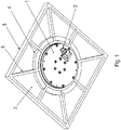
Figur 1 ist eine erste Bodenplatte 3 eines erfindungsgemäßen Systems zur induktiven Energieübertragung mit Doppelboden Schrägansicht gezeigt. - In
Figur 2 ist ein Querschnitt durch den Doppelboden dargestellt, wobei an einem in der ersten Bodenplatte 3 angeordneten Primärteil 1 ein Einspeisegerät 24 angeordnet ist. - In
Figur 3 ist ein Querschnitt durch den Doppelboden ohne das Einspeisegerät 24 dargestellt. - In der
Figur 4 ist eine Schrägansicht auf den Doppelboden dargestellt, wobei die erste Bodenplatte 3 samt Primärteil 1 explodiert dargestellt sind. - In der
Figur 5 ist eine Schrägansicht auf den Doppelboden mit eingebauter erster Bodenplatte 3 dargestellt. - Wie in den Figuren dargestellt, weist der Doppelboden zweite Bodenplatten 20 auf, welche in einen Unterboden bildenden Tragelementen 21 aufgenommen sind, und somit den von einem Mobilteil befahrbaren Boden bilden.
- Die zweite Bodenplatten 20 sind regelmäßig angeordnet und von jeweiligen Tragelementen 21 aufgenommen, welche mittels längenverstellbaren Stützen 22 über einem Rohboden 23 gehalten werden. Auf diese Weise ist ein genaues Ausrichten der zweiten Bodenplatten 20 ausführbar.
- Die zweiten Bodenplatten 20 sind vorzugsweise zumindest teilweise aus einem nichtmetallischen Material, wie beispielsweise Holz, Kunststoff und/oder Gips.
- Eine der zweiten Bodenplatten 20 ist an einer Stelle ersetzt durch eine erste Bodenplatte 3. Diese ersten Bodenplatte 3 ist vorzugsweise aus Metall, insbesondere Aluminium, gefertigt und weist an ihrer Unterseite Verdickungen auf, welche als Aufnahmering 4, als Rippen 5 und als Rahmen 6 ausgeformt sind. Somit ist die Tragfähigkeit der ersten Bodenplatte 3 sehr hoch. Denn der Rahmen 6 ist am äußeren Umfangsbereich der ersten Bodenplatte ausgebildet und der Aufnahmering 4 innerhalb dieses Rahmens 6, Rippen verbinden den Rahmen 6 mit dem Aufnahmering 4.
- Mittig im Aufnahmering 4 ist eine durch die erste Bodenplatte 3 durchgehende Ausnehmung ausgebildet, in welcher ein Primärteil 1 aufgenommen ist.
- Das Primärteil weise eine integrierte Primärwicklung auf, welche mit einem Wechselstrom beaufschlagbar ist.
- Ein auf dem Boden verfahrbar angeordnetes Mobilteil, insbesondere Fahrzeug oder automatisch geführtes Mobilteil, weist an seiner Unterseite eine Sekundärwicklung auf, welche mit der Primärwicklung des Primärteils 1 induktiv koppelbar ist.
- Die induzierte Spannung wird im Mobilteil gleichgerichtet und speist einen Energiespeicher des Mobilteils.
- Die Primärwicklung wird von einem Einspeisegerät 24 gespeist, welches hierzu einen Umrichter aufweist, der eine Wechselspannung zur Verfügung stellt, die einen Gyrator speist, dessen Bauteile, wie Kondensatoren und Induktivitäten, resonant auf die Frequenz der Wechselspannung abgestimmt sind. Somit wird das spannungsquellenartige Verhalten der Ausgangsseite des Umrichters in ein stromquellenartiges Verhalten der Ausgangsseite des Gyrators gewandelt. Aus der Ausgangsseite des Gyrators ist die Primärwicklung entweder direkt oder über einen Transformator gespeist.
- Das Primärteil 1 ist schraubverbunden mit der ersten Bodenplatte 3 oder mit einem, die erste Bodenplatte 3 aufnehmenden Tragelement 21.
- An der Unterseite des Primärteils ist eine Kabelzuführung 2 angeordnet, so dass von der Unterseite her ein Wechselstrom zur Primärwicklung zuführbar ist.
- Bei dem in
Figur 2 gezeigten direkten Anbau des Einspeisegeräts 24 an die Unterseite des Primärteils 1 ist die Zuführung von Wechselstrom direkt ausführbar, insbesondere alternativ auch durch eine Steckverbindung zwischen Primärteil 1 und Einspeisegerät 24. - Das Primärteil 1 und/oder das Einspeisegerät 24 weisen an ihrem äußeren Umfang zumindest teilweise ein metallisches gehäusebildendes Teil, also Gehäuseteil, auf. Somit ist eine wärmeleitende Verbindung zwischen Primärteil 1 und erster Bodenplatte 3 vorhanden. Bei direkt angebautem Einspeisegerät ist ebenfalls ein Wärmeübergang über das Primärteil zur ersten Bodenplatte 3 gewährleistet. Somit dient die erste Bodenplatte 3 auch zur Aufspreizung der Wärme und Ableitung an die Umgebung. Zusätzlich wird auch ein Teil des Wärmestroms über die Tragelemente 21 aufgespreizt und abgeleitet, da die Tragelemente aus Metall gefertigt sind.
- Da ebenso die Stützen 22 aus Metall gefertigt sind, ist auch hierdurch eine Wärmeaufspreizung und - Ableitung erreichbar. Die Stützen 22 sind längenverstellbar.
- Die Oberseite des Primärteils 1 ist bündig angeschlossen an die Oberseite der ersten Bodenplatte 3. Somit ist ein ungehindertes Überfahren durch das Mobilteil, insbesondere mit den Rädern des Mobilteils, ermöglicht.
- Die Verwendung von Aluminium bewirkt außerdem eine magnetisch abschirmende Wirkung bezüglich der von der Primärwicklung bewirkten Wechselmagnetfelder.
- Die Oberseite des Primärteils ist aus Kunststoff ausgeführt. Somit gelangt das von dem Primärteil erzeugte Magnetfeld ungehindert zur Sekundärwicklung.
- Vorzugsweise ist das Gehäuse des Primärteils mehrteilig ausgeführt, wobei ein metallisches Aufnahmeteil ein Oberteil aufnimmt, welches aus Kunststoff ausgeführt ist. Das Aufnahmeteil ist im Aufnahmering aufgenommen und durch die so realisierte Metall-Metall-Verbindung sehr gut wärmeleitend angebunden.
- Die Rippen 5 verlaufen vom Aufnahmering 4 aus sternstrahlenförmig, also alle in radialer Richtung, zum Rahmen 6.
- In Umfangsrichtung sind die Rippen 5 regelmäßig voneinander beabstandet.
-
- 1 Primärteil
- 2 Kabelzuführung
- 3 erste Bodenplatte, insbesondere Aufnahmeplatte
- 4 Aufnahmering
- 5 Rippe
- 6 Rahmen
- 20 zweite Bodenplatte
- 21 Tragelement, Unterboden
- 22 Stütze
- 23 Rohboden
- 24 Einspeisegerät
Claims (7)
- System zur berührungslosen Übertragung von elektrischer Energie an ein Mobilteil,wobei das System einen Doppelboden aufweist, in welchem ein Primärteil (1) angeordnet ist, der Doppelboden eine erste Bodenplatte (3) und zweite Bodenplatten (20), Tragelemente (21), Stützen (22) und einen Rohboden (23) aufweist,wobei die Bodenplatten (20) von Tragelementen (21), insbesondere einen Unterboden bildenden Tragelementen (21), aufgenommen sind,wobei die Tragelemente (21) von Stützen (22) über einem Rohboden (23) gehalten sind,dadurch gekennzeichnet, dassdie erste Bodenplatte (3) aus Aluminium gefertigt ist,wobei an der Unterseite der ersten Bodenplatte (3) ein Aufnahmering (4), Rippen (5) und ein Rahmen (6) ausgeformt ist,wobei die Rippen (5) vom Aufnahmering (4) sternstrahlenförmig in radialer Richtung zum Rahmen (6) verlaufenwobei der Aufnahmering (4) vom Rahmen (6) beabstandet ist,wobei das Primärteil (1) ein Aufnahmeteil und ein Oberteil aufweist,wobei das Oberteil im Aufnahmeteil aufgenommen ist und im Oberteil eine Primärwicklung angeordnet ist,wobei das Oberteil aus Kunststoff gefertigt istwobei das Aufnahmeteil aus Aluminium gefertigt ist,wobei das Aufnahmeteil im Aufnahmering (4) aufgenommen ist.
- System nach Anspruch 1,
dadurch gekennzeichnet, dass
der Rahmen (6) umlaufend und/oder geschlossen ausgeführt ist. - System nach mindestens einem der vorangegangenen Ansprüche,
dadurch gekennzeichnet, dass
die Rippen (5) in Umfangsrichtung regelmäßig voneinander beabstandet sind. - System nach mindestens einem der vorangegangenen Ansprüche,
dadurch gekennzeichnet, dass
die Stützen (22) längenveränderlich ausgeführt sind, insbesondere jede Stütze (22) zwei miteinander schraubverbundene Stützenteile aufweisen. - System nach mindestens einem der vorangegangenen Ansprüche,
dadurch gekennzeichnet, dass
die Stützen (22) und Tragelemente (21) aus Stahl gefertigt sind. - System nach mindestens einem der vorangegangenen Ansprüche,
dadurch gekennzeichnet, dassdas Oberteil eine Primärwicklung aufweist,insbesondere im Oberteil die Primärwicklung integriert ist. - System nach mindestens einem der vorangegangenen Ansprüche,
dadurch gekennzeichnet, dassam Primärteil (1) ein Einspeisegerät (24) angeordnet ist,wobei das Einspeisegerät (24) mittels eines Kabels versorgt ist und einen Umrichter aufweist, welcher an seinem wechselspannungsseitigen Anschluss mit einem als Gyrator ausgeführten Vierpol verbunden ist, dessen Bauteile, also Kondensator und Induktivität, resonant auf die Frequenz der am wechselspannungsseitigen Anschluss bereit gestellten Wechselspannung abgestimmt ist,wobei die Ausgangsseite des Vierpols die Primärwicklung speist.
Applications Claiming Priority (2)
| Application Number | Priority Date | Filing Date | Title |
|---|---|---|---|
| DE102017010217 | 2017-11-03 | ||
| PCT/EP2018/025269 WO2019086143A1 (de) | 2017-11-03 | 2018-10-18 | System zur berührungslosen übertragung von elektrischer energie an ein mobilteil |
Publications (2)
| Publication Number | Publication Date |
|---|---|
| EP3704799A1 EP3704799A1 (de) | 2020-09-09 |
| EP3704799B1 true EP3704799B1 (de) | 2022-10-05 |
Family
ID=64083050
Family Applications (1)
| Application Number | Title | Priority Date | Filing Date |
|---|---|---|---|
| EP18796361.6A Active EP3704799B1 (de) | 2017-11-03 | 2018-10-18 | System zur berührungslosen übertragung von elektrischer energie an ein mobilteil |
Country Status (5)
| Country | Link |
|---|---|
| US (1) | US11404908B2 (de) |
| EP (1) | EP3704799B1 (de) |
| CN (1) | CN111213322B (de) |
| DE (1) | DE102018008252A1 (de) |
| WO (1) | WO2019086143A1 (de) |
Families Citing this family (2)
| Publication number | Priority date | Publication date | Assignee | Title |
|---|---|---|---|---|
| DE102016219476A1 (de) * | 2016-10-07 | 2018-04-12 | Bayerische Motoren Werke Aktiengesellschaft | Induktive Ladeeinheit für ein Fahrzeug |
| US11063415B2 (en) * | 2019-01-16 | 2021-07-13 | Raymond & Lae Engineering, Inc. | Raised access floor panel with embedded sensors |
Family Cites Families (16)
| Publication number | Priority date | Publication date | Assignee | Title |
|---|---|---|---|---|
| CA2081764A1 (en) | 1990-04-27 | 1991-10-28 | Hiromasa Naka | Structure for supporting floor panels |
| JPH09268739A (ja) | 1996-04-02 | 1997-10-14 | Touseishiya Fab:Kk | 床板支持装置 |
| DE102008024217B4 (de) | 2008-05-19 | 2016-04-14 | Airbus Operations Gmbh | System zur kontaktlosen Daten- und Energieübertragung sowie Verwendung eines derartigen Systems in einem Flugzeug |
| DE102009057437B4 (de) | 2009-12-09 | 2023-03-16 | Sew-Eurodrive Gmbh & Co Kg | Anordnung zum induktiven Beladen eines Energiespeichers Fahrzeugs und Ladestation |
| KR101176960B1 (ko) | 2010-12-03 | 2012-08-30 | 한국생산기술연구원 | 마루블록장치 |
| JP5998737B2 (ja) | 2012-08-16 | 2016-09-28 | 株式会社Ihi | 移動式駐車設備 |
| JP6019929B2 (ja) * | 2012-08-24 | 2016-11-02 | 株式会社Ihi | 移動式駐車設備 |
| JP2014090528A (ja) | 2012-10-29 | 2014-05-15 | Hitachi Ltd | 移動体用非接触充電装置および移動体用非接触充電方法 |
| EP2842866A1 (de) * | 2013-08-30 | 2015-03-04 | Airbus Operations GmbH | Bodensystem für ein Fahrzeug und Fahrzeug mit einer Kabine und einem durch solch ein Bodensystem hergestellten Boden |
| DE102013221648B4 (de) * | 2013-10-24 | 2023-07-27 | Bayerische Motoren Werke Aktiengesellschaft | Diebstahlschutz für die Primärspule einer induktiven Ladestation |
| TWI539711B (zh) | 2014-01-02 | 2016-06-21 | 鴻騰精密科技股份有限公司 | 無線充電模組 |
| DE102014000347B4 (de) * | 2014-01-16 | 2022-10-06 | Sew-Eurodrive Gmbh & Co Kg | Primärteil, insbesondere bodengebundenes Primärteil, für ein System zur berührungslosen Energieübertragung |
| GB2529197B (en) | 2014-08-12 | 2019-06-26 | Nominal Sum Ltd | Loft flooring system |
| KR20160135609A (ko) | 2015-05-18 | 2016-11-28 | 주식회사 해광 | 프레임 상부에 설치되는 알루미늄 억세스 플로어 패널 |
| EP3607635B1 (de) * | 2017-04-07 | 2022-10-19 | Sew-Eurodrive GmbH & Co. KG | Verfahren zum herstellen eines systems zur induktiven übertragung von energie an ein mobilteil und vorrichtung zur durchführung des verfahrens |
| WO2019068366A1 (de) * | 2017-10-06 | 2019-04-11 | Sew-Eurodrive Gmbh & Co. Kg | System zur berührungslosen übertragung von elektrischer energie an ein mobilteil |
-
2018
- 2018-10-18 EP EP18796361.6A patent/EP3704799B1/de active Active
- 2018-10-18 WO PCT/EP2018/025269 patent/WO2019086143A1/de not_active Ceased
- 2018-10-18 DE DE102018008252.1A patent/DE102018008252A1/de active Pending
- 2018-10-18 US US16/761,447 patent/US11404908B2/en active Active
- 2018-10-18 CN CN201880066549.7A patent/CN111213322B/zh active Active
Also Published As
| Publication number | Publication date |
|---|---|
| EP3704799A1 (de) | 2020-09-09 |
| CN111213322A (zh) | 2020-05-29 |
| US20200395783A1 (en) | 2020-12-17 |
| CN111213322B (zh) | 2022-03-04 |
| WO2019086143A1 (de) | 2019-05-09 |
| DE102018008252A1 (de) | 2019-05-09 |
| US11404908B2 (en) | 2022-08-02 |
Similar Documents
| Publication | Publication Date | Title |
|---|---|---|
| DE102013010695B4 (de) | Vorrichtung mit Wicklungsanordnung und Anordnung, insbesondere Ladestation, zur berührungslosen Energieübertragung an ein Elektro-Fahrzeug, mit einer Wicklungsanordnung | |
| DE102012202472A1 (de) | Vorrichtung zur kontaktlosen Übertragung von Energie auf eine korrespondierende Vorrichtung | |
| DE102016004884B4 (de) | Antriebssystem mit einer Zwischenkreisverschienung | |
| EP3704799B1 (de) | System zur berührungslosen übertragung von elektrischer energie an ein mobilteil | |
| EP1961095B1 (de) | System, umfassend profilschiene und box | |
| DE102006025458B4 (de) | Übertragerkopf und Anlage zur berührungslosen Energieübertragung | |
| EP3692555B1 (de) | System zur berührungslosen übertragung von elektrischer energie an ein mobilteil | |
| DE102018005653A1 (de) | Drosselspule mit einer befestigungsnutenaufweisenden Basis | |
| DE102007023343A1 (de) | Übertragerkopf und Anlage | |
| DE19947368C1 (de) | Unterflurschienenanlage für Flurförderfahrzeuge mit berührungsloser induktiver Stromzuführung | |
| DE102006025460B4 (de) | Anlage mit einem Primärleitersystem | |
| EP3323134B1 (de) | Anordnung zur induktiven energieübertragung von einem primärleitersystem an ein eine sekundärwicklung aufweisendes fahrzeug | |
| WO2012085242A4 (de) | Antriebssystem mit einrichtungen zur vermeidung von elektromagnetischen störungen | |
| DE102017106726A1 (de) | Leistungsübertragungsvorrichtung | |
| DE102013007852B4 (de) | Anlage mit Gliederkette | |
| EP0517938B1 (de) | Modulares Einrichtungssystem | |
| DE102006025461B4 (de) | Übertragerkopf für eine Anlage zur berührungslosen Energieübertragung und Anlage mit einem Übertragerkopf | |
| EP2443964B1 (de) | Bausatz zur Erzeugung von miteinander verkettbaren Möbeln | |
| DE102018008251A1 (de) | Verfahren zur Detektion eines bewegbar angeordneten Mobilteils mit Sekundärwicklung und System zur Durchführung eines Verfahrens | |
| EP3698453B1 (de) | System zur berührungslosen übertragung von elektrischer energie an ein auf einem boden einer anlage verfahrbares mobilteil | |
| DE9311627U1 (de) | Hohlprofilverbund-Pfosten oder -Träger | |
| DE9404914U1 (de) | Niedervolt-Stromleitung | |
| DE29801765U1 (de) | Niederspannungs-Kabelhalter | |
| DE102012021024A1 (de) | Vorrichtung zur induktiven Erwärmung von Werkstücken | |
| DE102011105463A1 (de) | Kabelhalter im Trägersystem für Solarmodule |
Legal Events
| Date | Code | Title | Description |
|---|---|---|---|
| STAA | Information on the status of an ep patent application or granted ep patent |
Free format text: STATUS: UNKNOWN |
|
| STAA | Information on the status of an ep patent application or granted ep patent |
Free format text: STATUS: THE INTERNATIONAL PUBLICATION HAS BEEN MADE |
|
| PUAI | Public reference made under article 153(3) epc to a published international application that has entered the european phase |
Free format text: ORIGINAL CODE: 0009012 |
|
| STAA | Information on the status of an ep patent application or granted ep patent |
Free format text: STATUS: REQUEST FOR EXAMINATION WAS MADE |
|
| 17P | Request for examination filed |
Effective date: 20200603 |
|
| AK | Designated contracting states |
Kind code of ref document: A1 Designated state(s): AL AT BE BG CH CY CZ DE DK EE ES FI FR GB GR HR HU IE IS IT LI LT LU LV MC MK MT NL NO PL PT RO RS SE SI SK SM TR |
|
| AX | Request for extension of the european patent |
Extension state: BA ME |
|
| DAV | Request for validation of the european patent (deleted) | ||
| DAX | Request for extension of the european patent (deleted) | ||
| RIC1 | Information provided on ipc code assigned before grant |
Ipc: B60L 53/30 20190101ALI20220308BHEP Ipc: B60L 53/12 20190101ALI20220308BHEP Ipc: H02J 50/12 20160101ALI20220308BHEP Ipc: H04B 5/00 20060101AFI20220308BHEP |
|
| GRAP | Despatch of communication of intention to grant a patent |
Free format text: ORIGINAL CODE: EPIDOSNIGR1 |
|
| STAA | Information on the status of an ep patent application or granted ep patent |
Free format text: STATUS: GRANT OF PATENT IS INTENDED |
|
| INTG | Intention to grant announced |
Effective date: 20220527 |
|
| GRAS | Grant fee paid |
Free format text: ORIGINAL CODE: EPIDOSNIGR3 |
|
| GRAA | (expected) grant |
Free format text: ORIGINAL CODE: 0009210 |
|
| STAA | Information on the status of an ep patent application or granted ep patent |
Free format text: STATUS: THE PATENT HAS BEEN GRANTED |
|
| AK | Designated contracting states |
Kind code of ref document: B1 Designated state(s): AL AT BE BG CH CY CZ DE DK EE ES FI FR GB GR HR HU IE IS IT LI LT LU LV MC MK MT NL NO PL PT RO RS SE SI SK SM TR |
|
| REG | Reference to a national code |
Ref country code: GB Ref legal event code: FG4D Free format text: NOT ENGLISH |
|
| REG | Reference to a national code |
Ref country code: CH Ref legal event code: EP |
|
| REG | Reference to a national code |
Ref country code: AT Ref legal event code: REF Ref document number: 1523403 Country of ref document: AT Kind code of ref document: T Effective date: 20221015 |
|
| REG | Reference to a national code |
Ref country code: IE Ref legal event code: FG4D Free format text: LANGUAGE OF EP DOCUMENT: GERMAN |
|
| REG | Reference to a national code |
Ref country code: DE Ref legal event code: R096 Ref document number: 502018010795 Country of ref document: DE |
|
| REG | Reference to a national code |
Ref country code: LT Ref legal event code: MG9D |
|
| REG | Reference to a national code |
Ref country code: NL Ref legal event code: MP Effective date: 20221005 |
|
| PG25 | Lapsed in a contracting state [announced via postgrant information from national office to epo] |
Ref country code: NL Free format text: LAPSE BECAUSE OF FAILURE TO SUBMIT A TRANSLATION OF THE DESCRIPTION OR TO PAY THE FEE WITHIN THE PRESCRIBED TIME-LIMIT Effective date: 20221005 |
|
| PG25 | Lapsed in a contracting state [announced via postgrant information from national office to epo] |
Ref country code: SE Free format text: LAPSE BECAUSE OF FAILURE TO SUBMIT A TRANSLATION OF THE DESCRIPTION OR TO PAY THE FEE WITHIN THE PRESCRIBED TIME-LIMIT Effective date: 20221005 Ref country code: PT Free format text: LAPSE BECAUSE OF FAILURE TO SUBMIT A TRANSLATION OF THE DESCRIPTION OR TO PAY THE FEE WITHIN THE PRESCRIBED TIME-LIMIT Effective date: 20230206 Ref country code: NO Free format text: LAPSE BECAUSE OF FAILURE TO SUBMIT A TRANSLATION OF THE DESCRIPTION OR TO PAY THE FEE WITHIN THE PRESCRIBED TIME-LIMIT Effective date: 20230105 Ref country code: LT Free format text: LAPSE BECAUSE OF FAILURE TO SUBMIT A TRANSLATION OF THE DESCRIPTION OR TO PAY THE FEE WITHIN THE PRESCRIBED TIME-LIMIT Effective date: 20221005 Ref country code: FI Free format text: LAPSE BECAUSE OF FAILURE TO SUBMIT A TRANSLATION OF THE DESCRIPTION OR TO PAY THE FEE WITHIN THE PRESCRIBED TIME-LIMIT Effective date: 20221005 Ref country code: ES Free format text: LAPSE BECAUSE OF FAILURE TO SUBMIT A TRANSLATION OF THE DESCRIPTION OR TO PAY THE FEE WITHIN THE PRESCRIBED TIME-LIMIT Effective date: 20221005 |
|
| PG25 | Lapsed in a contracting state [announced via postgrant information from national office to epo] |
Ref country code: RS Free format text: LAPSE BECAUSE OF FAILURE TO SUBMIT A TRANSLATION OF THE DESCRIPTION OR TO PAY THE FEE WITHIN THE PRESCRIBED TIME-LIMIT Effective date: 20221005 Ref country code: PL Free format text: LAPSE BECAUSE OF FAILURE TO SUBMIT A TRANSLATION OF THE DESCRIPTION OR TO PAY THE FEE WITHIN THE PRESCRIBED TIME-LIMIT Effective date: 20221005 Ref country code: LV Free format text: LAPSE BECAUSE OF FAILURE TO SUBMIT A TRANSLATION OF THE DESCRIPTION OR TO PAY THE FEE WITHIN THE PRESCRIBED TIME-LIMIT Effective date: 20221005 Ref country code: IS Free format text: LAPSE BECAUSE OF FAILURE TO SUBMIT A TRANSLATION OF THE DESCRIPTION OR TO PAY THE FEE WITHIN THE PRESCRIBED TIME-LIMIT Effective date: 20230205 Ref country code: HR Free format text: LAPSE BECAUSE OF FAILURE TO SUBMIT A TRANSLATION OF THE DESCRIPTION OR TO PAY THE FEE WITHIN THE PRESCRIBED TIME-LIMIT Effective date: 20221005 Ref country code: GR Free format text: LAPSE BECAUSE OF FAILURE TO SUBMIT A TRANSLATION OF THE DESCRIPTION OR TO PAY THE FEE WITHIN THE PRESCRIBED TIME-LIMIT Effective date: 20230106 |
|
| REG | Reference to a national code |
Ref country code: CH Ref legal event code: PL |
|
| REG | Reference to a national code |
Ref country code: BE Ref legal event code: MM Effective date: 20221031 |
|
| PG25 | Lapsed in a contracting state [announced via postgrant information from national office to epo] |
Ref country code: LU Free format text: LAPSE BECAUSE OF NON-PAYMENT OF DUE FEES Effective date: 20221018 |
|
| REG | Reference to a national code |
Ref country code: DE Ref legal event code: R097 Ref document number: 502018010795 Country of ref document: DE |
|
| PG25 | Lapsed in a contracting state [announced via postgrant information from national office to epo] |
Ref country code: SM Free format text: LAPSE BECAUSE OF FAILURE TO SUBMIT A TRANSLATION OF THE DESCRIPTION OR TO PAY THE FEE WITHIN THE PRESCRIBED TIME-LIMIT Effective date: 20221005 Ref country code: RO Free format text: LAPSE BECAUSE OF FAILURE TO SUBMIT A TRANSLATION OF THE DESCRIPTION OR TO PAY THE FEE WITHIN THE PRESCRIBED TIME-LIMIT Effective date: 20221005 Ref country code: MC Free format text: LAPSE BECAUSE OF FAILURE TO SUBMIT A TRANSLATION OF THE DESCRIPTION OR TO PAY THE FEE WITHIN THE PRESCRIBED TIME-LIMIT Effective date: 20221005 Ref country code: LI Free format text: LAPSE BECAUSE OF NON-PAYMENT OF DUE FEES Effective date: 20221031 Ref country code: EE Free format text: LAPSE BECAUSE OF FAILURE TO SUBMIT A TRANSLATION OF THE DESCRIPTION OR TO PAY THE FEE WITHIN THE PRESCRIBED TIME-LIMIT Effective date: 20221005 Ref country code: DK Free format text: LAPSE BECAUSE OF FAILURE TO SUBMIT A TRANSLATION OF THE DESCRIPTION OR TO PAY THE FEE WITHIN THE PRESCRIBED TIME-LIMIT Effective date: 20221005 Ref country code: CZ Free format text: LAPSE BECAUSE OF FAILURE TO SUBMIT A TRANSLATION OF THE DESCRIPTION OR TO PAY THE FEE WITHIN THE PRESCRIBED TIME-LIMIT Effective date: 20221005 Ref country code: CH Free format text: LAPSE BECAUSE OF NON-PAYMENT OF DUE FEES Effective date: 20221031 |
|
| PLBE | No opposition filed within time limit |
Free format text: ORIGINAL CODE: 0009261 |
|
| STAA | Information on the status of an ep patent application or granted ep patent |
Free format text: STATUS: NO OPPOSITION FILED WITHIN TIME LIMIT |
|
| PG25 | Lapsed in a contracting state [announced via postgrant information from national office to epo] |
Ref country code: SK Free format text: LAPSE BECAUSE OF FAILURE TO SUBMIT A TRANSLATION OF THE DESCRIPTION OR TO PAY THE FEE WITHIN THE PRESCRIBED TIME-LIMIT Effective date: 20221005 Ref country code: AL Free format text: LAPSE BECAUSE OF FAILURE TO SUBMIT A TRANSLATION OF THE DESCRIPTION OR TO PAY THE FEE WITHIN THE PRESCRIBED TIME-LIMIT Effective date: 20221005 |
|
| 26N | No opposition filed |
Effective date: 20230706 |
|
| GBPC | Gb: european patent ceased through non-payment of renewal fee |
Effective date: 20230105 |
|
| PG25 | Lapsed in a contracting state [announced via postgrant information from national office to epo] |
Ref country code: BE Free format text: LAPSE BECAUSE OF NON-PAYMENT OF DUE FEES Effective date: 20221031 |
|
| PG25 | Lapsed in a contracting state [announced via postgrant information from national office to epo] |
Ref country code: IE Free format text: LAPSE BECAUSE OF NON-PAYMENT OF DUE FEES Effective date: 20221018 Ref country code: GB Free format text: LAPSE BECAUSE OF NON-PAYMENT OF DUE FEES Effective date: 20230105 |
|
| PG25 | Lapsed in a contracting state [announced via postgrant information from national office to epo] |
Ref country code: SI Free format text: LAPSE BECAUSE OF FAILURE TO SUBMIT A TRANSLATION OF THE DESCRIPTION OR TO PAY THE FEE WITHIN THE PRESCRIBED TIME-LIMIT Effective date: 20221005 Ref country code: FR Free format text: LAPSE BECAUSE OF NON-PAYMENT OF DUE FEES Effective date: 20221205 |
|
| PG25 | Lapsed in a contracting state [announced via postgrant information from national office to epo] |
Ref country code: CY Free format text: LAPSE BECAUSE OF FAILURE TO SUBMIT A TRANSLATION OF THE DESCRIPTION OR TO PAY THE FEE WITHIN THE PRESCRIBED TIME-LIMIT Effective date: 20221005 |
|
| PG25 | Lapsed in a contracting state [announced via postgrant information from national office to epo] |
Ref country code: MK Free format text: LAPSE BECAUSE OF FAILURE TO SUBMIT A TRANSLATION OF THE DESCRIPTION OR TO PAY THE FEE WITHIN THE PRESCRIBED TIME-LIMIT Effective date: 20221005 Ref country code: IT Free format text: LAPSE BECAUSE OF FAILURE TO SUBMIT A TRANSLATION OF THE DESCRIPTION OR TO PAY THE FEE WITHIN THE PRESCRIBED TIME-LIMIT Effective date: 20221005 Ref country code: HU Free format text: LAPSE BECAUSE OF FAILURE TO SUBMIT A TRANSLATION OF THE DESCRIPTION OR TO PAY THE FEE WITHIN THE PRESCRIBED TIME-LIMIT; INVALID AB INITIO Effective date: 20181018 |
|
| PG25 | Lapsed in a contracting state [announced via postgrant information from national office to epo] |
Ref country code: TR Free format text: LAPSE BECAUSE OF FAILURE TO SUBMIT A TRANSLATION OF THE DESCRIPTION OR TO PAY THE FEE WITHIN THE PRESCRIBED TIME-LIMIT Effective date: 20221005 |
|
| PG25 | Lapsed in a contracting state [announced via postgrant information from national office to epo] |
Ref country code: BG Free format text: LAPSE BECAUSE OF FAILURE TO SUBMIT A TRANSLATION OF THE DESCRIPTION OR TO PAY THE FEE WITHIN THE PRESCRIBED TIME-LIMIT Effective date: 20221005 |
|
| PG25 | Lapsed in a contracting state [announced via postgrant information from national office to epo] |
Ref country code: MT Free format text: LAPSE BECAUSE OF FAILURE TO SUBMIT A TRANSLATION OF THE DESCRIPTION OR TO PAY THE FEE WITHIN THE PRESCRIBED TIME-LIMIT Effective date: 20221005 |
|
| REG | Reference to a national code |
Ref country code: AT Ref legal event code: MM01 Ref document number: 1523403 Country of ref document: AT Kind code of ref document: T Effective date: 20231018 |
|
| PG25 | Lapsed in a contracting state [announced via postgrant information from national office to epo] |
Ref country code: AT Free format text: LAPSE BECAUSE OF NON-PAYMENT OF DUE FEES Effective date: 20231018 |
|
| PG25 | Lapsed in a contracting state [announced via postgrant information from national office to epo] |
Ref country code: AT Free format text: LAPSE BECAUSE OF NON-PAYMENT OF DUE FEES Effective date: 20231018 |
|
| PGFP | Annual fee paid to national office [announced via postgrant information from national office to epo] |
Ref country code: DE Payment date: 20251031 Year of fee payment: 8 |
|
| PGFP | Annual fee paid to national office [announced via postgrant information from national office to epo] |
Ref country code: AT Payment date: 20260410 Year of fee payment: 5 |