EP3704055B1 - Automatisch geführtes fahrzeug mit gabeln zum bewegen einer fliesentragstruktur - Google Patents
Automatisch geführtes fahrzeug mit gabeln zum bewegen einer fliesentragstruktur Download PDFInfo
- Publication number
- EP3704055B1 EP3704055B1 EP18825770.3A EP18825770A EP3704055B1 EP 3704055 B1 EP3704055 B1 EP 3704055B1 EP 18825770 A EP18825770 A EP 18825770A EP 3704055 B1 EP3704055 B1 EP 3704055B1
- Authority
- EP
- European Patent Office
- Prior art keywords
- fork
- respect
- tiles
- angle
- support structure
- Prior art date
- Legal status (The legal status is an assumption and is not a legal conclusion. Google has not performed a legal analysis and makes no representation as to the accuracy of the status listed.)
- Active
Links
Images


Classifications
-
- B—PERFORMING OPERATIONS; TRANSPORTING
- B66—HOISTING; LIFTING; HAULING
- B66F—HOISTING, LIFTING, HAULING OR PUSHING, NOT OTHERWISE PROVIDED FOR, e.g. DEVICES WHICH APPLY A LIFTING OR PUSHING FORCE DIRECTLY TO THE SURFACE OF A LOAD
- B66F9/00—Devices for lifting or lowering bulky or heavy goods for loading or unloading purposes
- B66F9/06—Devices for lifting or lowering bulky or heavy goods for loading or unloading purposes movable, with their loads, on wheels or the like, e.g. fork-lift trucks
- B66F9/075—Constructional features or details
- B66F9/12—Platforms; Forks; Other load supporting or gripping members
- B66F9/16—Platforms; Forks; Other load supporting or gripping members inclinable relative to mast
-
- B—PERFORMING OPERATIONS; TRANSPORTING
- B66—HOISTING; LIFTING; HAULING
- B66F—HOISTING, LIFTING, HAULING OR PUSHING, NOT OTHERWISE PROVIDED FOR, e.g. DEVICES WHICH APPLY A LIFTING OR PUSHING FORCE DIRECTLY TO THE SURFACE OF A LOAD
- B66F9/00—Devices for lifting or lowering bulky or heavy goods for loading or unloading purposes
- B66F9/06—Devices for lifting or lowering bulky or heavy goods for loading or unloading purposes movable, with their loads, on wheels or the like, e.g. fork-lift trucks
- B66F9/063—Automatically guided
-
- B—PERFORMING OPERATIONS; TRANSPORTING
- B66—HOISTING; LIFTING; HAULING
- B66F—HOISTING, LIFTING, HAULING OR PUSHING, NOT OTHERWISE PROVIDED FOR, e.g. DEVICES WHICH APPLY A LIFTING OR PUSHING FORCE DIRECTLY TO THE SURFACE OF A LOAD
- B66F9/00—Devices for lifting or lowering bulky or heavy goods for loading or unloading purposes
- B66F9/06—Devices for lifting or lowering bulky or heavy goods for loading or unloading purposes movable, with their loads, on wheels or the like, e.g. fork-lift trucks
- B66F9/075—Constructional features or details
- B66F9/0755—Position control; Position detectors
-
- B—PERFORMING OPERATIONS; TRANSPORTING
- B66—HOISTING; LIFTING; HAULING
- B66F—HOISTING, LIFTING, HAULING OR PUSHING, NOT OTHERWISE PROVIDED FOR, e.g. DEVICES WHICH APPLY A LIFTING OR PUSHING FORCE DIRECTLY TO THE SURFACE OF A LOAD
- B66F9/00—Devices for lifting or lowering bulky or heavy goods for loading or unloading purposes
- B66F9/06—Devices for lifting or lowering bulky or heavy goods for loading or unloading purposes movable, with their loads, on wheels or the like, e.g. fork-lift trucks
- B66F9/075—Constructional features or details
- B66F9/08—Masts; Guides; Chains
- B66F9/082—Masts; Guides; Chains inclinable
Definitions
- the present invention relates to the technical sector concerning automatically-guided vehicles (AGV) provided with forks for moving a support structure of tiles.
- AGV automatically-guided vehicles
- a known automatically-guided vehicle provided with forks comprises: a vertical framework; a carriage which is vertically movable along the vertical framework; and a first fork and a second fork which are borne by the carriage.
- a known support structure of tiles comprises: a plurality of uprights (usually four in number), each of which is provided with a first coupling profile at a relative first end and a second coupling profile at a relative second end, opposite the relative first end; a loading plane for receiving the tiles, which is interposed between the first coupling profile and the second coupling profile of each upright of the plurality of uprights.
- the automatically-guided vehicle positions in such a way that the forks contact the lower surface of the loading plane; thereafter the carriage for raising the forks is activated. At this point, the automatically-guided vehicle can move the support structure of tiles and release them where required, activating the carriage to lower the forks.
- This operation is carried out at height (even up to 4-5 metres, in consideration of the height of the store, where the support structures of the tiles are located, and the height of the pre-existing stack) and with the first support structure loaded with tiles.
- the weight of the first support structure of tiles and the tiles loaded thereon determines a flexion of the vertical framework which is greater in proportion with the height of the first support structure of tiles to be loaded on the stack: therefore, the vertical framework is inclined forwards (that is, towards the first support structure of tiles) by an angle with respect to a vertical plane.
- the forks also incline downwards by an angle with respect to a horizontal plane, due to the fact that they are borne by the vertical framework via the carriage. Further, the forks further incline downwards with respect to the horizontal plane, due to the flexion to which the forks are subject due to the weight that they have to bear.
- the first support structure of tiles is not horizontal but inclined downwards by an angle, which could prevent the coupling of the first coupling profile of each upright of the first support structure of tiles couples to the second coupling profile of each upright of the second support structure of tiles, which is at the top of the stack.
- the first support structure of tiles and the tiles loaded thereon might fall: the first support structure of tiles and the tiles loaded thereon can therefore be damaged. Further, the falling of the first support structure of tiles might strike and damage one or more support structures of tiles of the pre-existing stack and/or the automatically-guided vehicle itself. The damage, as can be imagined, might be of a very great extent.
- US 4 957 408 discloses a forklift comprising: tilt sensors mounted on the prongs; a computer which calculates the tilt angles of the prongs, based on the output signals from the sensors; a driving device which receives the output signals from the computer and brings the prongs into the horizontal.
- the aim of the present invention consists in obviating the above-mentioned drawbacks.
- the first fork and the second fork flex downwards and incline by an angle with respect to the horizontal plane, as explained in the foregoing.
- the first sensor detects the inclination and communicates it to the control unit.
- the control unit can command the actuator means to move the first fork and the second fork up until the inclination of the first fork and the second fork with respect to the horizontal plane is lower than a first angle of tolerance.
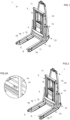
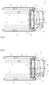
- reference numeral (1) denotes in its entirety an automatically-guided vehicle provided with forks for moving a support structure of tiles, comprising: a vertical framework (3); a carriage (4) which is vertically movable along the vertical framework (3); a first fork (5) and a second fork (6) which are borne by the carriage (4); a first sensor (7) that is mounted on board the first fork (5) or the second fork (6), for respectively detecting an inclination of the first fork (5) or the second fork (6) with respect to a horizontal plane (xy) ( figures 5-9 illustrate the outline of this plane); a control unit (8) which is connected to the first sensor (7); actuator means (9) which are arranged so as to move the first fork (5) and the second fork (6) in order to correct the inclination of the first fork (5) and the second fork (6) with respect to the horizontal plane (xy).
- the control unit (8) ( figure 3, 4 ) is connected to the actuator means (9) and is
- the vertical framework (3) can comprise a pair of uprights (10) superiorly connected by a cross-member (11) to form a frame.
- the carriage (4) can be coupled to the vertical framework (3) in order to slide along the pair of uprights (10).
- the first fork (5) and the second fork (6) share, substantially in equal parts, the weight of a support structure di tiles (2) to be lifted. Therefore, the forks are stressed equally and the first sensor (7) can be arranged either on the first fork (5) or the second fork (6).
- the first sensor (7) is preferably a first horizontal inclinometer.
- the first fork (5) or the second fork (6) preferably comprises a first housing (12) ( figures 3, 4 ) to receive the first horizontal inclinometer.
- the first housing (12) can be an undercut fashioned on the upper part of the first fork (5) or of the second fork (6).
- the automatically-guided vehicle (1) can comprise a third sensor, for example a second horizontal inclinometer, which is mounted on board the second fork (6) to detect the inclination of the second fork (6) (embodiment not illustrated); the first sensor (7), for example the first horizontal inclinometer, is mounted on-board the first fork (5) in order to detect the inclination of the first fork (5).
- a third sensor for example a second horizontal inclinometer
- the third sensor can be connected to the control unit (8) and the control unit (8) can be configured for commanding the actuator means (9) as a function of the signal received from the first sensor (7) and from the third sensor.
- the second fork (6) can comprise a second housing (not illustrated) in order to receive the second horizontal inclinometer; the second housing can be an undercut fashioned on the upper part of the second fork (6).
- the automatically-guided vehicle (1) comprises a frame (21).
- the automatically-guided vehicle (1) can comprise a main body (14).
- the automatically-guided vehicle (1) can comprise a horizontal frame (15) which projects from the main body (14).
- the horizontal frame (15) can have a substantially planar shape, in the sense that the relative thickness can be much smaller (at least five times, preferably at least ten times smaller) than the width and length of the horizontal frame (15).
- the horizontal frame (15) can project from the lower portion of the main body (14), and is distant from the flooring, for example between five and thirty centimetres from the floor surface.
- the horizontal frame (15) can in turn comprise a first arm (16) and a second arm (17) which are flanked to one another and which are flanked to the first fork (5) and the second fork (6), and a first rolling element (18) and a second rolling element (19) which are borne respectively by the first arm (16) and by the second arm (17).
- the first fork (5) and the second fork (6) can be interposed between the first arm (16) and the second arm (17).
- the first fork (5) and the second fork (6) are rotatable with respect to the carriage (4), while the actuator means (9) comprise a first actuator (91) for rotating the first fork (5) and the second fork (6) with respect to the carriage (4).
- the first fork (5) and the second fork (6) are preferably rotoidally coupled to the carriage (4) with respect to a first hinge axis (Y1) ( figure 6A ) that is substantially horizontal.
- the vertical framework (3) is rotatable with respect to the frame (21) ( figure 6 ) of the automatically-guided vehicle (1), while the actuator means (9) comprise a second actuator (92) for rotating the vertical framework (3) with respect to the frame (21).
- the rotation of the vertical framework (3) by means of the second actuator (92) can correct the inclination of the first fork (5) and the second fork (6) with respect to the horizontal plane (xy).
- the vertical framework (3) is preferably rotoidally coupled to the frame (21) with respect to a second hinge axis (Y2) (see figure 6 once more) which is substantially horizontal.
- a third embodiment which forms part of the present claimed invention unites the first embodiment with the second embodiment. Therefore, the vertical framework (3) is rotatable with respect to the frame (21) of the automatically-guided vehicle (1), the first fork (5) and the second fork (6) are rotatable with respect to the carriage (4), the actuator means (9) comprise a first actuator (91) for rotating the first fork (5) and the second fork (6) with respect to the carriage (4) and a second actuator (92) for rotating the vertical framework (3) with respect to the frame (21).
- the activating of both the first actuator (91) and the second actuator (92) has the effect of moving the first fork (5) and the second fork (6) in order to correct the inclination of the first fork (5) and the second fork (6) with respect to the horizontal plane (xy).
- a further object of the present invention is a method for moving a support structure of tiles (2), by means of the automatically-guided vehicle (1) as according to the third embodiment, comprising steps of: raising a support structure of tiles (2); detecting the inclination of the first fork (5) or the second fork (6) with respect to a horizontal plane (xy); if the first fork (5) or the second fork (6) is inclined with respect to the horizontal plane (xy) by a greater angle than a first angle of tolerance, moving the first fork (5) and the second fork (6) in order to correct the inclination of the first fork (5) and the second fork (6) with respect to the horizontal plane (xy), until the first fork (5) and the second fork (6) are inclined with respect to the horizontal plane (xy) by a smaller angle than the first angle of tolerance.
- the automatically-guided vehicle (1) comprises a second sensor (13) which is mounted on board the vertical framework (3) for detecting the inclination of the vertical framework (3) with respect to a vertical plane (yz) (see the broken lines illustrated in figures 5-9 ).
- the control unit (8) is connected to the second sensor (13).
- the second sensor (13) is preferably a vertical inclinometer.
- the vertical framework (3) is rotatable with respect to the frame (21) of the automatically-guided vehicle (1)
- the first fork (5) and the second fork (6) are rotatable with respect to the carriage (4)
- the actuator means (9) comprise a first actuator (91) for rotating the first fork (5) and the second fork (6) with respect to the carriage (4) and a second actuator (92) for rotating the vertical framework (3) with respect to the frame (21).
- a further object of the present invention concerns a method for moving a support structure of tiles (2), by means of the automatically-guided vehicle (1) defined in the foregoing with the fourth embodiment, which method comprises, with respect to the method already defined in the foregoing, the step of detecting the inclination of the vertical framework (3) with respect to a vertical plane (yz).
- the method further comprises: if the first fork (5) or the second fork (6) is inclined with respect to the horizontal plane (xy) by a greater angle than a first angle of tolerance, carrying out following sub-steps:
- the second angle of tolerance can be of about 2 degrees.
- Sub-step b) is preferably carried out only after sub-step a) has been carried out, if the first fork (5) and the second fork (6) are still inclined with respect to the horizontal plane (xy) by a greater angle than the first angle of tolerance.
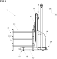
- Each support structure of tiles (2) comprises: a plurality of uprights (24) (usually four in number), each of which is provided with a first coupling profile (23) at a relative first end and a second coupling profile (25) at a relative second end, opposite the relative first end; a loading plane (26) for receiving the tiles, which is interposed between the first coupling profile (23) and the second coupling profile (25) of each upright (24) of the plurality of uprights.
- the automatically-guided vehicle (1) nears the first support structure of tiles (2) to be lifted and stacked (see figure 5 ), until the horizontal frame (15) is arranged below the first support structure of tiles (2). Thereafter, the carriage (4) is activated by motor means (not illustrated), to lift the forks (5, 6) and then also the first support structure of tiles (2) (see figure 6 ).
- the weight of the first support structure of tiles (2) determines an inclination of the vertical framework (3) with respect to the vertical plane (yz), detected by the second sensor (13), as well as an inclination of the first fork (5) and the second fork (6) with respect to the horizontal plane (xy), detected by the first sensor (12).
- first fork (5) (on which the first sensor (12) is fixed, but like considerations are also true if the first sensor (12) is arranged on the second fork (6)) is inclined with respect to the horizontal plane (xy) by a greater angle than a first angle of tolerance, the following sub-steps might be carried out:
- the first fork (5) and the second fork (6) are inclined with respect to the horizontal plane (xy) by a smaller angle than the first angle of tolerance.
- the automatically-guided vehicle (1) nears ( figure 7 ) to the pre-existing stack (22) until the horizontal frame (15) is arranged beneath the support structure of tiles of the stack (22) positioned on the flooring ( fig.8 ).
- the carriage (4) is activated by the motor means to lower the forks (5, 6) until the first coupling profile (23) of each upright (24) of the first support structure of tiles (2) couples to the second coupling profile (25) of each upright (24) of the second support structure of tiles (222) ( figure 9 ).
Landscapes
- Engineering & Computer Science (AREA)
- Transportation (AREA)
- Structural Engineering (AREA)
- Civil Engineering (AREA)
- Life Sciences & Earth Sciences (AREA)
- Geology (AREA)
- Mechanical Engineering (AREA)
- Forklifts And Lifting Vehicles (AREA)
Claims (6)
- Automatisch geführtes Fahrzeug (1), das mit Gabeln zum Bewegen einer Trägerstruktur für Fliesen (2) ausgestattet ist, umfassend:einen vertikalen Rahmen (3);einen Wagen (4), der entlang des vertikalen Rahmens (3) vertikal beweglich ist;eine erste Gabel (5) und eine zweite Gabel (6), die vom Wagen (4) getragen werden;einen ersten Sensor (7);eine Steuereinheit (8), die mit dem ersten Sensor (7) verbunden ist;Betätigungsmittel (9), die so angeordnet sind, dass sie die erste Gabel (5) und die zweite Gabel (6) bewegen, um die Neigung der ersten Gabel (5) und der zweiten Gabel (6) relativ zur Horizontalebene (xy) zu korrigieren;wobei die Steuereinheit (8) mit den Betätigungsmitteln (9) verbunden ist und so konfiguriert ist, dass sie die Betätigungsmittel (9) in Abhängigkeit von dem vom ersten Sensor (7) empfangenen Signal steuert;dadurch gekennzeichnet, dass:der erste Sensor (7) an Bord der ersten Gabel (5) oder der zweiten Gabel (6) montiert ist, um jeweils eine Neigung der ersten Gabel (5) oder der zweiten Gabel (6) relativ zu einer Horizontalebene (xy) zu erfassen;die erste Gabel (5) und die zweite Gabel (6) relativ zum Wagen (4) drehbar sind, und wobei die Betätigungsmittel (9) einen ersten Betätiger (91) umfassen, um die erste Gabel (5) und die zweite Gabel (6) relativ zum Wagen (4) zu drehen;es einen Rahmen (21) umfasst, wobei der vertikale Rahmen (3) relativ zum Rahmen (21) drehbar ist, und wobei die Betätigungsmittel (9) einen zweiten Betätiger (92) umfassen, um den vertikalen Rahmen (3) relativ zum Rahmen (21) zu drehen.
- Das automatisch geführte Fahrzeug (1) mit Gabeln gemäß Anspruch 1, wobei: es einen zweiten Sensor (13) umfasst, der an Bord des vertikalen Rahmens (3) montiert ist, um die Neigung des vertikalen Rahmens (3) relativ zu einer Vertikalebene (yz) zu erfassen; die Steuereinheit (8) mit dem zweiten Sensor (13) verbunden ist.
- Das automatisch geführte Fahrzeug (1) mit Gabeln gemäß einem der vorhergehenden Ansprüche, wobei der erste Sensor (7) ein erster horizontaler Neigungsmesser ist.
- Das automatisch geführte Fahrzeug (1) mit Gabeln gemäß einem der Ansprüche 2 bis 3, wobei der zweite Sensor (13) ein vertikaler Neigungsmesser ist.
- Verfahren zum Bewegen einer Trägerstruktur für Fliesen (2) mittels eines automatisch geführten Fahrzeugs (1) gemäß Anspruch 1, umfassend die Schritte:Anheben einer Trägerstruktur für Fliesen (2);Erfassen der Neigung der ersten Gabel (5) oder der zweiten Gabel (6) relativ zu einer Horizontalebene (xy);falls die erste Gabel (5) oder die zweite Gabel (6) relativ zur Horizontalebene (xy) um einen Winkel größer als ein erster Toleranzwinkel geneigt ist, Bewegen der ersten Gabel (5) und der zweiten Gabel (6), um die Neigung der ersten Gabel (5) und der zweiten Gabel (6) relativ zur Horizontalebene (xy) zu korrigieren, bis die erste Gabel (5) und die zweite Gabel (6) relativ zur Horizontalebene (xy) um einen Winkel kleiner als der erste Toleranzwinkel geneigt sind.
- Das Verfahren zum Bewegen einer Trägerstruktur für Fliesen (2) gemäß dem vorhergehenden Anspruch mittels eines automatisch geführten Fahrzeugs (1) gemäß Anspruch 2, wobei:das Verfahren einen Schritt zum Erfassen der Neigung des vertikalen Rahmens (3) relativ zu einer Vertikalebene (yz) umfasst;falls die erste Gabel (5) oder die zweite Gabel (6) relativ zur Horizontalebene (xy) um einen Winkel größer als ein erster Toleranzwinkel geneigt ist, die folgenden Teil-Schritte ausführen:falls der vertikale Rahmen (3) relativ zur Vertikalebene (yz) um einen Winkel größer als ein zweiter Toleranzwinkel geneigt ist, Drehen des vertikalen Rahmens (3) mittels des zweiten Betätigers (92), um die Neigung des vertikalen Rahmens (3) relativ zur Vertikalebene (yz) zu korrigieren, bis der vertikale Rahmen (3) relativ zur Vertikalebene (yz) um einen Winkel kleiner als der zweite Toleranzwinkel geneigt ist;Drehen der ersten Gabel (5) und der zweiten Gabel (6) mittels des ersten Betätigers (91), um die Neigung der ersten Gabel (5) und der zweite Gabel (6) relativ zur Horizontalebene (xy) zu korrigieren, bis die erste Gabel (5) und die zweite Gabel (6) relativ zur Horizontalebene (xy) um einen Winkel kleiner als der erste Toleranzwinkel geneigt sind.
Applications Claiming Priority (2)
| Application Number | Priority Date | Filing Date | Title |
|---|---|---|---|
| IT102017000123704A IT201700123704A1 (it) | 2017-10-31 | 2017-10-31 | Veicolo a guida automatica provvisto di forche per la movimentazione di una struttura di supporto di piastrelle |
| PCT/IB2018/058501 WO2019087072A1 (en) | 2017-10-31 | 2018-10-30 | An automatically-guided vehicle provided with forks for moving a support structure of tiles |
Publications (2)
| Publication Number | Publication Date |
|---|---|
| EP3704055A1 EP3704055A1 (de) | 2020-09-09 |
| EP3704055B1 true EP3704055B1 (de) | 2025-05-07 |
Family
ID=61526998
Family Applications (1)
| Application Number | Title | Priority Date | Filing Date |
|---|---|---|---|
| EP18825770.3A Active EP3704055B1 (de) | 2017-10-31 | 2018-10-30 | Automatisch geführtes fahrzeug mit gabeln zum bewegen einer fliesentragstruktur |
Country Status (6)
| Country | Link |
|---|---|
| EP (1) | EP3704055B1 (de) |
| CN (1) | CN111542487B (de) |
| BR (1) | BR112020008507B1 (de) |
| ES (1) | ES3035980T3 (de) |
| IT (1) | IT201700123704A1 (de) |
| WO (1) | WO2019087072A1 (de) |
Families Citing this family (3)
| Publication number | Priority date | Publication date | Assignee | Title |
|---|---|---|---|---|
| CN113104768A (zh) * | 2021-05-07 | 2021-07-13 | 安徽宇锋仓储设备有限公司 | 一种前移式叉车agv |
| CN114132871B (zh) * | 2022-01-10 | 2023-12-29 | 湖州哥伦布物流科技有限公司 | 一种用于agv叉车的车身结构 |
| US12583718B1 (en) * | 2025-05-30 | 2026-03-24 | Visionnav Robotics Usa Inc. | Control method for automated guided forklift, and automated guided forklift and controller applying same |
Family Cites Families (6)
| Publication number | Priority date | Publication date | Assignee | Title |
|---|---|---|---|---|
| US4957408A (en) * | 1988-04-06 | 1990-09-18 | Toyota Jidosha Kabushiki Kaisha | Device for controlling a fork of a forklift |
| JPH05213592A (ja) * | 1992-02-07 | 1993-08-24 | Mitsubishi Heavy Ind Ltd | フォークリフトにおけるヒンジドフォークの制御装置 |
| US7980808B2 (en) * | 2004-05-03 | 2011-07-19 | Jervis B. Webb Company | Automatic transport loading system and method |
| CN104925707A (zh) * | 2015-06-19 | 2015-09-23 | 林德(中国)叉车有限公司 | 一种自动控制叉车货叉倾斜角度的装置 |
| CN205076766U (zh) * | 2015-10-15 | 2016-03-09 | 浙江诺力机械股份有限公司 | 一种适用于工业车辆的自动调平装置 |
| CN107161916B (zh) * | 2017-02-13 | 2022-12-06 | 林德(中国)叉车有限公司 | 一种前移式叉车的自动调平装置和方法 |
-
2017
- 2017-10-31 IT IT102017000123704A patent/IT201700123704A1/it unknown
-
2018
- 2018-10-30 CN CN201880084396.9A patent/CN111542487B/zh not_active Expired - Fee Related
- 2018-10-30 ES ES18825770T patent/ES3035980T3/es active Active
- 2018-10-30 EP EP18825770.3A patent/EP3704055B1/de active Active
- 2018-10-30 WO PCT/IB2018/058501 patent/WO2019087072A1/en not_active Ceased
- 2018-10-30 BR BR112020008507-3A patent/BR112020008507B1/pt not_active IP Right Cessation
Also Published As
| Publication number | Publication date |
|---|---|
| BR112020008507B1 (pt) | 2022-12-20 |
| EP3704055A1 (de) | 2020-09-09 |
| WO2019087072A1 (en) | 2019-05-09 |
| BR112020008507A2 (pt) | 2020-11-03 |
| CN111542487A (zh) | 2020-08-14 |
| IT201700123704A1 (it) | 2019-05-01 |
| ES3035980T3 (en) | 2025-09-11 |
| CN111542487B (zh) | 2022-05-31 |
Similar Documents
| Publication | Publication Date | Title |
|---|---|---|
| US7953514B2 (en) | Article storage facility and operating method thereof | |
| CA2743189C (en) | Floating forks for lift vehicles | |
| TWI382950B (zh) | Transfer system | |
| KR101790285B1 (ko) | 화물 카트 연동 물류이송용 이송로봇 | |
| CN111792582A (zh) | 用于物料搬运车辆的负载搬运模块 | |
| MX2010011943A (es) | Sistema y metodo para carga automatica de transporte. | |
| JP7794692B2 (ja) | 制御方法、制御装置、及び制御システム | |
| WO2019087072A1 (en) | An automatically-guided vehicle provided with forks for moving a support structure of tiles | |
| JP2008230841A (ja) | 物品搬送装置 | |
| JP2003128395A (ja) | 産業車両における荷役作業支援装置及び産業車両 | |
| JP4941728B2 (ja) | 物品搬送装置 | |
| JP5765577B2 (ja) | スタッカークレーン | |
| JP4038807B2 (ja) | スタッカークレーン | |
| JP3701004B2 (ja) | 無人フォークリフト | |
| JP4331316B2 (ja) | 自動倉庫における荷の移載位置検出装置 | |
| JP4973927B2 (ja) | 物品搬送装置 | |
| CN111247085B (zh) | 砖块运输和储存系统 | |
| JP5182565B2 (ja) | 物品搬送装置 | |
| KR20230052744A (ko) | 단적재 리프트 장치 | |
| JPH02110100A (ja) | 無人フォークリフト | |
| JPH07144714A (ja) | スタッカクレーンの昇降制御装置 | |
| JPH064000U (ja) | 無人フォ−クリフト | |
| JP5857478B2 (ja) | 物品収納設備 | |
| WO2025223532A1 (zh) | 一种底盘、托盘搬运机器人、方法、电子设备及存储介质 | |
| WO2026058833A1 (ja) | パレット用段積み段ばらし装置 |
Legal Events
| Date | Code | Title | Description |
|---|---|---|---|
| STAA | Information on the status of an ep patent application or granted ep patent |
Free format text: STATUS: UNKNOWN |
|
| STAA | Information on the status of an ep patent application or granted ep patent |
Free format text: STATUS: THE INTERNATIONAL PUBLICATION HAS BEEN MADE |
|
| PUAI | Public reference made under article 153(3) epc to a published international application that has entered the european phase |
Free format text: ORIGINAL CODE: 0009012 |
|
| STAA | Information on the status of an ep patent application or granted ep patent |
Free format text: STATUS: REQUEST FOR EXAMINATION WAS MADE |
|
| 17P | Request for examination filed |
Effective date: 20200527 |
|
| AK | Designated contracting states |
Kind code of ref document: A1 Designated state(s): AL AT BE BG CH CY CZ DE DK EE ES FI FR GB GR HR HU IE IS IT LI LT LU LV MC MK MT NL NO PL PT RO RS SE SI SK SM TR |
|
| AX | Request for extension of the european patent |
Extension state: BA ME |
|
| DAV | Request for validation of the european patent (deleted) | ||
| DAX | Request for extension of the european patent (deleted) | ||
| STAA | Information on the status of an ep patent application or granted ep patent |
Free format text: STATUS: EXAMINATION IS IN PROGRESS |
|
| 17Q | First examination report despatched |
Effective date: 20221129 |
|
| RAP1 | Party data changed (applicant data changed or rights of an application transferred) |
Owner name: SACMI TECH S.P.A. |
|
| P01 | Opt-out of the competence of the unified patent court (upc) registered |
Effective date: 20230328 |
|
| GRAP | Despatch of communication of intention to grant a patent |
Free format text: ORIGINAL CODE: EPIDOSNIGR1 |
|
| STAA | Information on the status of an ep patent application or granted ep patent |
Free format text: STATUS: GRANT OF PATENT IS INTENDED |
|
| GRAJ | Information related to disapproval of communication of intention to grant by the applicant or resumption of examination proceedings by the epo deleted |
Free format text: ORIGINAL CODE: EPIDOSDIGR1 |
|
| STAA | Information on the status of an ep patent application or granted ep patent |
Free format text: STATUS: EXAMINATION IS IN PROGRESS |
|
| INTG | Intention to grant announced |
Effective date: 20240930 |
|
| INTC | Intention to grant announced (deleted) | ||
| GRAP | Despatch of communication of intention to grant a patent |
Free format text: ORIGINAL CODE: EPIDOSNIGR1 |
|
| STAA | Information on the status of an ep patent application or granted ep patent |
Free format text: STATUS: GRANT OF PATENT IS INTENDED |
|
| INTG | Intention to grant announced |
Effective date: 20241203 |
|
| GRAS | Grant fee paid |
Free format text: ORIGINAL CODE: EPIDOSNIGR3 |
|
| GRAA | (expected) grant |
Free format text: ORIGINAL CODE: 0009210 |
|
| STAA | Information on the status of an ep patent application or granted ep patent |
Free format text: STATUS: THE PATENT HAS BEEN GRANTED |
|
| AK | Designated contracting states |
Kind code of ref document: B1 Designated state(s): AL AT BE BG CH CY CZ DE DK EE ES FI FR GB GR HR HU IE IS IT LI LT LU LV MC MK MT NL NO PL PT RO RS SE SI SK SM TR |
|
| REG | Reference to a national code |
Ref country code: GB Ref legal event code: FG4D |
|
| REG | Reference to a national code |
Ref country code: CH Ref legal event code: EP |
|
| REG | Reference to a national code |
Ref country code: DE Ref legal event code: R096 Ref document number: 602018081783 Country of ref document: DE |
|
| REG | Reference to a national code |
Ref country code: IE Ref legal event code: FG4D |
|
| REG | Reference to a national code |
Ref country code: NL Ref legal event code: MP Effective date: 20250507 |
|
| REG | Reference to a national code |
Ref country code: ES Ref legal event code: FG2A Ref document number: 3035980 Country of ref document: ES Kind code of ref document: T3 Effective date: 20250911 |
|
| PG25 | Lapsed in a contracting state [announced via postgrant information from national office to epo] |
Ref country code: PT Free format text: LAPSE BECAUSE OF FAILURE TO SUBMIT A TRANSLATION OF THE DESCRIPTION OR TO PAY THE FEE WITHIN THE PRESCRIBED TIME-LIMIT Effective date: 20250908 Ref country code: FI Free format text: LAPSE BECAUSE OF FAILURE TO SUBMIT A TRANSLATION OF THE DESCRIPTION OR TO PAY THE FEE WITHIN THE PRESCRIBED TIME-LIMIT Effective date: 20250507 |
|
| REG | Reference to a national code |
Ref country code: LT Ref legal event code: MG9D |
|
| PG25 | Lapsed in a contracting state [announced via postgrant information from national office to epo] |
Ref country code: NO Free format text: LAPSE BECAUSE OF FAILURE TO SUBMIT A TRANSLATION OF THE DESCRIPTION OR TO PAY THE FEE WITHIN THE PRESCRIBED TIME-LIMIT Effective date: 20250807 Ref country code: GR Free format text: LAPSE BECAUSE OF FAILURE TO SUBMIT A TRANSLATION OF THE DESCRIPTION OR TO PAY THE FEE WITHIN THE PRESCRIBED TIME-LIMIT Effective date: 20250808 |
|
| PG25 | Lapsed in a contracting state [announced via postgrant information from national office to epo] |
Ref country code: PL Free format text: LAPSE BECAUSE OF FAILURE TO SUBMIT A TRANSLATION OF THE DESCRIPTION OR TO PAY THE FEE WITHIN THE PRESCRIBED TIME-LIMIT Effective date: 20250507 Ref country code: NL Free format text: LAPSE BECAUSE OF FAILURE TO SUBMIT A TRANSLATION OF THE DESCRIPTION OR TO PAY THE FEE WITHIN THE PRESCRIBED TIME-LIMIT Effective date: 20250507 |
|
| REG | Reference to a national code |
Ref country code: AT Ref legal event code: MK05 Ref document number: 1792334 Country of ref document: AT Kind code of ref document: T Effective date: 20250507 |
|
| PG25 | Lapsed in a contracting state [announced via postgrant information from national office to epo] |
Ref country code: BG Free format text: LAPSE BECAUSE OF FAILURE TO SUBMIT A TRANSLATION OF THE DESCRIPTION OR TO PAY THE FEE WITHIN THE PRESCRIBED TIME-LIMIT Effective date: 20250507 |
|
| PG25 | Lapsed in a contracting state [announced via postgrant information from national office to epo] |
Ref country code: HR Free format text: LAPSE BECAUSE OF FAILURE TO SUBMIT A TRANSLATION OF THE DESCRIPTION OR TO PAY THE FEE WITHIN THE PRESCRIBED TIME-LIMIT Effective date: 20250507 |
|
| PG25 | Lapsed in a contracting state [announced via postgrant information from national office to epo] |
Ref country code: AT Free format text: LAPSE BECAUSE OF FAILURE TO SUBMIT A TRANSLATION OF THE DESCRIPTION OR TO PAY THE FEE WITHIN THE PRESCRIBED TIME-LIMIT Effective date: 20250507 |
|
| PG25 | Lapsed in a contracting state [announced via postgrant information from national office to epo] |
Ref country code: RS Free format text: LAPSE BECAUSE OF FAILURE TO SUBMIT A TRANSLATION OF THE DESCRIPTION OR TO PAY THE FEE WITHIN THE PRESCRIBED TIME-LIMIT Effective date: 20250807 |
|
| PG25 | Lapsed in a contracting state [announced via postgrant information from national office to epo] |
Ref country code: IS Free format text: LAPSE BECAUSE OF FAILURE TO SUBMIT A TRANSLATION OF THE DESCRIPTION OR TO PAY THE FEE WITHIN THE PRESCRIBED TIME-LIMIT Effective date: 20250907 |
|
| PG25 | Lapsed in a contracting state [announced via postgrant information from national office to epo] |
Ref country code: LV Free format text: LAPSE BECAUSE OF FAILURE TO SUBMIT A TRANSLATION OF THE DESCRIPTION OR TO PAY THE FEE WITHIN THE PRESCRIBED TIME-LIMIT Effective date: 20250507 |
|
| PG25 | Lapsed in a contracting state [announced via postgrant information from national office to epo] |
Ref country code: DK Free format text: LAPSE BECAUSE OF FAILURE TO SUBMIT A TRANSLATION OF THE DESCRIPTION OR TO PAY THE FEE WITHIN THE PRESCRIBED TIME-LIMIT Effective date: 20250507 Ref country code: SM Free format text: LAPSE BECAUSE OF FAILURE TO SUBMIT A TRANSLATION OF THE DESCRIPTION OR TO PAY THE FEE WITHIN THE PRESCRIBED TIME-LIMIT Effective date: 20250507 |
|
| PGFP | Annual fee paid to national office [announced via postgrant information from national office to epo] |
Ref country code: IT Payment date: 20251028 Year of fee payment: 8 |
|
| PG25 | Lapsed in a contracting state [announced via postgrant information from national office to epo] |
Ref country code: CZ Free format text: LAPSE BECAUSE OF FAILURE TO SUBMIT A TRANSLATION OF THE DESCRIPTION OR TO PAY THE FEE WITHIN THE PRESCRIBED TIME-LIMIT Effective date: 20250507 |
|
| PG25 | Lapsed in a contracting state [announced via postgrant information from national office to epo] |
Ref country code: EE Free format text: LAPSE BECAUSE OF FAILURE TO SUBMIT A TRANSLATION OF THE DESCRIPTION OR TO PAY THE FEE WITHIN THE PRESCRIBED TIME-LIMIT Effective date: 20250507 |
|
| PG25 | Lapsed in a contracting state [announced via postgrant information from national office to epo] |
Ref country code: SK Free format text: LAPSE BECAUSE OF FAILURE TO SUBMIT A TRANSLATION OF THE DESCRIPTION OR TO PAY THE FEE WITHIN THE PRESCRIBED TIME-LIMIT Effective date: 20250507 Ref country code: RO Free format text: LAPSE BECAUSE OF FAILURE TO SUBMIT A TRANSLATION OF THE DESCRIPTION OR TO PAY THE FEE WITHIN THE PRESCRIBED TIME-LIMIT Effective date: 20250507 |
|
| PGFP | Annual fee paid to national office [announced via postgrant information from national office to epo] |
Ref country code: ES Payment date: 20251107 Year of fee payment: 8 |
|
| REG | Reference to a national code |
Ref country code: DE Ref legal event code: R097 Ref document number: 602018081783 Country of ref document: DE |
|
| PLBE | No opposition filed within time limit |
Free format text: ORIGINAL CODE: 0009261 |
|
| STAA | Information on the status of an ep patent application or granted ep patent |
Free format text: STATUS: NO OPPOSITION FILED WITHIN TIME LIMIT |
|
| REG | Reference to a national code |
Ref country code: CH Ref legal event code: L10 Free format text: ST27 STATUS EVENT CODE: U-0-0-L10-L00 (AS PROVIDED BY THE NATIONAL OFFICE) Effective date: 20260318 |
|
| 26N | No opposition filed |
Effective date: 20260210 |