EP3703982B1 - Airbag-ansaugmodule und zugehörige ventilanordnungen - Google Patents
Airbag-ansaugmodule und zugehörige ventilanordnungen Download PDFInfo
- Publication number
- EP3703982B1 EP3703982B1 EP18873484.2A EP18873484A EP3703982B1 EP 3703982 B1 EP3703982 B1 EP 3703982B1 EP 18873484 A EP18873484 A EP 18873484A EP 3703982 B1 EP3703982 B1 EP 3703982B1
- Authority
- EP
- European Patent Office
- Prior art keywords
- inflation
- airbag cushion
- valve
- inflator
- nozzles
- Prior art date
- Legal status (The legal status is an assumption and is not a legal conclusion. Google has not performed a legal analysis and makes no representation as to the accuracy of the status listed.)
- Active
Links
Images






Classifications
-
- B—PERFORMING OPERATIONS; TRANSPORTING
- B60—VEHICLES IN GENERAL
- B60R—VEHICLES, VEHICLE FITTINGS, OR VEHICLE PARTS, NOT OTHERWISE PROVIDED FOR
- B60R21/00—Arrangements or fittings on vehicles for protecting or preventing injuries to occupants or pedestrians in case of accidents or other traffic risks
- B60R21/02—Occupant safety arrangements or fittings, e.g. crash pads
- B60R21/16—Inflatable occupant restraints or confinements designed to inflate upon impact or impending impact, e.g. air bags
- B60R21/26—Inflatable occupant restraints or confinements designed to inflate upon impact or impending impact, e.g. air bags characterised by the inflation fluid source or means to control inflation fluid flow
- B60R21/30—Inflatable occupant restraints or confinements designed to inflate upon impact or impending impact, e.g. air bags characterised by the inflation fluid source or means to control inflation fluid flow with means to draw ambient air into the flow line and mix such air with the inflation fluid
-
- B—PERFORMING OPERATIONS; TRANSPORTING
- B60—VEHICLES IN GENERAL
- B60R—VEHICLES, VEHICLE FITTINGS, OR VEHICLE PARTS, NOT OTHERWISE PROVIDED FOR
- B60R21/00—Arrangements or fittings on vehicles for protecting or preventing injuries to occupants or pedestrians in case of accidents or other traffic risks
- B60R21/02—Occupant safety arrangements or fittings, e.g. crash pads
- B60R21/16—Inflatable occupant restraints or confinements designed to inflate upon impact or impending impact, e.g. air bags
- B60R21/20—Arrangements for storing inflatable members in their non-use or deflated condition; Arrangement or mounting of air bag modules or components
- B60R21/217—Inflation fluid source retainers, e.g. reaction canisters; Connection of bags, covers, diffusers or inflation fluid sources therewith or together
- B60R21/2176—Inflation fluid source retainers, e.g. reaction canisters; Connection of bags, covers, diffusers or inflation fluid sources therewith or together the air bag components being completely enclosed in a soft or semi-rigid housing or cover
-
- B—PERFORMING OPERATIONS; TRANSPORTING
- B60—VEHICLES IN GENERAL
- B60R—VEHICLES, VEHICLE FITTINGS, OR VEHICLE PARTS, NOT OTHERWISE PROVIDED FOR
- B60R21/00—Arrangements or fittings on vehicles for protecting or preventing injuries to occupants or pedestrians in case of accidents or other traffic risks
- B60R21/02—Occupant safety arrangements or fittings, e.g. crash pads
- B60R21/16—Inflatable occupant restraints or confinements designed to inflate upon impact or impending impact, e.g. air bags
- B60R21/26—Inflatable occupant restraints or confinements designed to inflate upon impact or impending impact, e.g. air bags characterised by the inflation fluid source or means to control inflation fluid flow
- B60R21/264—Inflatable occupant restraints or confinements designed to inflate upon impact or impending impact, e.g. air bags characterised by the inflation fluid source or means to control inflation fluid flow using instantaneous generation of gas, e.g. pyrotechnic
-
- B—PERFORMING OPERATIONS; TRANSPORTING
- B60—VEHICLES IN GENERAL
- B60R—VEHICLES, VEHICLE FITTINGS, OR VEHICLE PARTS, NOT OTHERWISE PROVIDED FOR
- B60R21/00—Arrangements or fittings on vehicles for protecting or preventing injuries to occupants or pedestrians in case of accidents or other traffic risks
- B60R21/02—Occupant safety arrangements or fittings, e.g. crash pads
- B60R21/16—Inflatable occupant restraints or confinements designed to inflate upon impact or impending impact, e.g. air bags
- B60R21/26—Inflatable occupant restraints or confinements designed to inflate upon impact or impending impact, e.g. air bags characterised by the inflation fluid source or means to control inflation fluid flow
- B60R21/268—Inflatable occupant restraints or confinements designed to inflate upon impact or impending impact, e.g. air bags characterised by the inflation fluid source or means to control inflation fluid flow using instantaneous release of stored pressurised gas
-
- B—PERFORMING OPERATIONS; TRANSPORTING
- B60—VEHICLES IN GENERAL
- B60R—VEHICLES, VEHICLE FITTINGS, OR VEHICLE PARTS, NOT OTHERWISE PROVIDED FOR
- B60R21/00—Arrangements or fittings on vehicles for protecting or preventing injuries to occupants or pedestrians in case of accidents or other traffic risks
- B60R21/34—Protecting non-occupants of a vehicle, e.g. pedestrians
- B60R21/36—Protecting non-occupants of a vehicle, e.g. pedestrians using airbags
-
- B—PERFORMING OPERATIONS; TRANSPORTING
- B60—VEHICLES IN GENERAL
- B60R—VEHICLES, VEHICLE FITTINGS, OR VEHICLE PARTS, NOT OTHERWISE PROVIDED FOR
- B60R21/00—Arrangements or fittings on vehicles for protecting or preventing injuries to occupants or pedestrians in case of accidents or other traffic risks
- B60R21/02—Occupant safety arrangements or fittings, e.g. crash pads
- B60R21/16—Inflatable occupant restraints or confinements designed to inflate upon impact or impending impact, e.g. air bags
- B60R21/26—Inflatable occupant restraints or confinements designed to inflate upon impact or impending impact, e.g. air bags characterised by the inflation fluid source or means to control inflation fluid flow
- B60R2021/26076—Inflatable occupant restraints or confinements designed to inflate upon impact or impending impact, e.g. air bags characterised by the inflation fluid source or means to control inflation fluid flow characterised by casing
-
- B—PERFORMING OPERATIONS; TRANSPORTING
- B60—VEHICLES IN GENERAL
- B60R—VEHICLES, VEHICLE FITTINGS, OR VEHICLE PARTS, NOT OTHERWISE PROVIDED FOR
- B60R21/00—Arrangements or fittings on vehicles for protecting or preventing injuries to occupants or pedestrians in case of accidents or other traffic risks
- B60R21/02—Occupant safety arrangements or fittings, e.g. crash pads
- B60R21/16—Inflatable occupant restraints or confinements designed to inflate upon impact or impending impact, e.g. air bags
- B60R21/26—Inflatable occupant restraints or confinements designed to inflate upon impact or impending impact, e.g. air bags characterised by the inflation fluid source or means to control inflation fluid flow
- B60R2021/26094—Inflatable occupant restraints or confinements designed to inflate upon impact or impending impact, e.g. air bags characterised by the inflation fluid source or means to control inflation fluid flow characterised by fluid flow controlling valves
Definitions
- Airbag assemblies that aspirate ambient air into the airbag cushion during deployment may allow for alleviating some of these difficulties.
- existing aspirating airbag assemblies suffer from many drawbacks, such as being large, bulky, and/or complicated, often requiring many different components and valve mechanisms.
- such assemblies may be desirable for such assemblies to provide a closed-open-closed function whereby the assembly is initially closed, opens during inflation to draw in ambient air to assist with inflation gases, and then closes again at a desired point during or after inflation to prevent undue leakage of inflation gases and/or ambient air, thus compromising restraint.
- Some such assemblies provide an undesired delay in closure and allow more leakage than would otherwise be desired at or near the end of inflation.
- the inventive concepts disclosed herein may allow for replacement of complicated components of previous systems by, for example, molding some or all of the jets or gas directing components integrally into a plastic housing, sewing or otherwise coupling relatively simple valve features into the assembly to simply and economically control the direction of aspirating gas flow, and/or employ pre-crash deployment sensor(s) to increase the amount of time allowed for aspiration.
- the jets and/or inflation nozzles may be positioned above the flaps and/or valves relative to the airbag cushion or otherwise such that the flaps/valves are positioned in between the aspiration inlet and the airbag cushion. This may allow for decoupling the valve functionality from the inflation nozzles to improve upon desired closure characteristics and/or reduce unwanted leakage.
- the function of introducing inflation gases into the cushion may be decoupled from the function of closing the valve(s)/flap(s) to allow for more efficient closure by allowing for pressure from the cushion to close the valve(s)/flap(s) independent of the inflation gases entering the cushion through the inflation nozzles/tubes from the inflator.
- an airbag cushion inflation module is defined by claim 1.
- the at least one valve may be positioned adjacent to the aspiration inlet and/or spaced apart from the inflation nozzles.
- the assembly may comprise an airbag cushion, and an inflation module comprising an aspiration side and an inflation side.
- the inflation module may comprise an inflator and a plurality of inflation nozzles, such as high-velocity inflation nozzles, fluidly coupled with the inflator.
- the plurality of inflation nozzles may be configured to deliver inflation gas from the inflator into the airbag cushion from the inflation side of the inflation module.
- a housing may be coupled to the airbag cushion adjacent to the inflation side of the inflation module, wherein the housing comprises an aspiration inlet configured to allow for receipt of ambient air into the airbag cushion during inflation of the airbag cushion, and wherein the plurality of inflation nozzles is configured to, upon actuation of the inflator, draw ambient air into the airbag cushion along with the inflation gas from the inflator.
- the airbag cushion assembly may further comprise a valve assembly comprising at least one valve configured to open upon actuation of the inflator and configured to close during inflation of the airbag cushion to prevent air and inflation gas from exiting through the aspiration inlet.
- the at least one valve is positioned between the aspiration inlet and the plurality of inflation nozzles.
- the aspiration side of the inflation module may be positioned opposite from the inflation side.
- the at least one valve may be configured to automatically close at a predetermined stage during inflation of the airbag cushion.
- the at least one valve may comprise a plurality of flaps.
- at least one of the plurality of flaps may comprise a butterfly flap configured to automatically open and close at least two separate openings of the aspiration inlet.
- the housing may comprise an inflation housing.
- the plurality of inflation nozzles may be positioned within the inflation housing.
- Some embodiments may further comprise a valve assembly housing coupled with the inflation housing. The valve assembly may be positioned within the valve assembly housing.
- the at least one valve may be biased towards a closed position.
- the module comprises an inflator housing comprising an aspiration inlet configured to allow for receipt of ambient air into the airbag cushion during inflation of an airbag cushion coupled with the airbag cushion inflation module; an inflator; and a plurality of high-velocity inflation nozzles, configured to deliver inflation gas from the inflator.
- the inflation nozzles are configured to, upon actuation of the inflator, draw ambient air through the aspiration inlet.
- the module further comprises a valve assembly comprising at least one valve flap configured to open upon actuation of the inflator, wherein the at least one valve flap is configured to close following aspiration of an airbag cushion coupled with the airbag cushion inflation module to prevent air and inflation gas from exiting through the aspiration inlet following inflation of the airbag cushion.
- valve assembly may be configured such that the at least one valve flap is spaced apart from nozzle openings of the plurality of inflation nozzles.
- valve assembly may be configured to bias the at least one valve flap towards a closed position in which the aspiration inlet is blocked.
- the valve assembly may be configured such that the at least one valve flap is fully positioned on the opposite side of the plurality of high-velocity nozzles relative to the airbag cushion in both an open position in which the aspiration inlet is open and a closed position in which the aspiration inlet is closed by the at least one valve flap.
- the valve assembly may be configured such that the at least one valve is positioned away from a flow path of the plurality of high-velocity nozzles.
- Some embodiments may further comprise a valve assembly housing configured to house the at least one valve flap.
- the valve assembly housing may be positioned on an opposite side of the plurality of high-velocity nozzles relative to the airbag cushion.
- the module may comprise a housing configured to be coupled with an airbag cushion.
- the housing comprises an aspiration inlet configured to allow for receipt of ambient air into the airbag cushion during inflation of the airbag cushion.
- the module may further comprise an inflator configured to facilitate inflation of the airbag cushion and a plurality of inflation nozzles fluidly coupled with the inflator.
- the plurality of inflation nozzles may be configured to deliver inflation gas from the inflator and to, upon actuation of the inflator, draw ambient air though the aspiration inlet along with the inflation gas from the inflator.
- a valve assembly may be positioned between the plurality of inflation nozzles and the aspiration inlet. The valve assembly may be configured to function in an open position in which ambient air is allowed to pass through the aspiration inlet and a closed position in which at least a portion of the valve assembly at least substantially blocks the aspiration inlet.
- valve assembly may comprise one or more (in some such embodiments, a plurality) valve flaps configured to automatically open and close during inflation of the airbag cushion from pressure differentials between an inside of the airbag cushion and ambient air pressure.
- valve assembly may further comprise means for biasing the one or more valve flaps towards the closed position, such as a spring-loaded hinge.
- valve assembly may comprise valve flap(s) made up of a flexible material configured to flex and change shape during aspiration.
- Apparatus, methods, and systems are disclosed herein relating to aspirating airbag cushion assemblies configured to utilize ambient air, in some cases along with inflation gas, to inflate larger airbag cushions, such as, in some embodiments, airbag cushions for multiple occupants, airbag cushions for autonomous vehicles, or pedestrian airbag cushions.
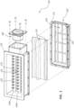
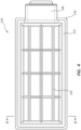
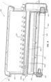
- FIGS. 1-4 depict an airbag inflation module 110 for use in connection with certain airbag cushion assemblies disclosed herein.
- Airbag inflation module 110 comprises an inflation module housing 120 comprising an inflator 140 and a plurality of inflation nozzles 135 and a valve assembly 150 comprising a valve housing 151 and one or more valves.
- airbag inflation module 110 is configured to be coupled to an airbag cushion (not depicted in FIG. 1 ).
- the valve(s) of valve assembly are configured to selectively block an aspiration inlet to allow for inflation of an airbag cushion in stages.
- housings 120 and 151 are depicted as separate housings coupled with one another, it should be understood that, in alternative embodiments, all of the various elements of inflation module 110 may be housed in a single housing (in some embodiments an integral housing).
- valve(s) of valve assembly 150 are preferably configured to operate in a closed configuration initially, and then automatically open during inflation, which may be caused by generating a partial vacuum within the airbag cushion by, for example, the inflation gas of nozzles 135. Following inflation, the system may be configured to automatically close again to maintain gases (both ambient air and inflation gas) in the cushion during occupant contact.
- the system may be specifically configured to provide for these three stages automatically at desired times by virtue of the positioning and configuration of the valve(s) and inflation nozzles.
- Housing 120 comprises an aspiration inlet 125 at one end that is configured to allow for receipt of ambient air into the airbag cushion during inflation of the airbag cushion.
- aspiration inlet 125 is defined by a plurality of openings positioned in between inflator conduits 130a, 130b, and 130c, each of which comprises a plurality of high-velocity nozzles 135, along with a plurality of support members 132 extending perpendicular to the inflator conduits 130a, 130b, and 130c.
- aspiration inlet 125 is configured to fluidly couple an internal portion of an airbag cushion with ambient air upon opening a suitable valve to allow for introduction of ambient air into the airbag cushion along with inflation gas from nozzles 135.
- valve assembly housing 151 may provide an aspiration inlet 155 that may be fluidly coupled with aspiration inlet 125.
- aspiration inlets 125 and 155 are blocked, or at least partially blocked, to prevent or at least inhibit ambient air from entering the accompanying airbag cushion.
- valves 152 are in an open configuration, aspiration inlets 125 and 155 provide a series of openings through which ambient air can flow to facilitate inflation of the airbag cushion.
- each of the high-velocity nozzles 135 is configured to keep the inflation gas delivered therethrough in a relatively tight column while being delivered into the airbag cushion rather than expanding into a plume of gas. This may further facilitate creation of the desired pressure differential to drive the aspiration process.
- the pressure driving the nozzles 135 not exceed about 3,447 MPa (500psi).
- this pressure be at least about 0.689 MPa (100 psi).
- the pressured within the inflator conduits 130 is between about 0.689 MPa (100 psi) and about 3.447 MPa (500 psi), or, in some such embodiments, between 0.689 MPa (100 psi) and 3.447 MPa (500psi).
- the airbag inflation module 110 may be configured such that the gas delivered from nozzles 135 is below supersonic velocities. This may be useful in preventing the plume created by the incoming gas from getting too large. Thus, it may be preferred to keep the gas from nozzles 135 as close to being delivered in a vertical column/stream as possible.
- the nozzles be spaced apart from one another sufficiently such that the streamlines of the expanding gas do not intersect, or at least intersect minimally.
- the nozzles are spaced apart with the maximum amount of space in between each adjacent nozzle within the area allotted to the aspiration inlet, such as the case in the depicted embodiment.
- Airbag inflation module 110 further comprises an inflator 140.
- Inflator 140 is fluidly coupled with inflator conduits 130a, 130b, and 130c, which, in turn, are fluidly coupled with nozzles 135.
- Nozzles 135 are configured to deliver inflation gas from inflator 140 into an airbag cushion at a high rate of velocity and/or rate of volume/time such that ambient air is drawn into the airbag cushion with the inflation gas from nozzles 135 through aspiration inlets 125 and/or 155 such that the airbag cushion is inflated by both the inflation gas and the ambient air together.
- Valve assembly 150 comprises one or more valve flaps 152.
- valve flaps 152 are provided, namely, a central butterfly valve flap 152b, and two opposing valve flaps 152a and 152c, each of which is configured to block a portion of aspiration inlet 155, which may be defined by one or more cross-members 153.
- valve flaps 152 may be sufficiently flexible such that the flaps flex during inflation, as depicted in FIGS. 1 and 6 . In some embodiments, however, valve flaps 152 may be sufficiently rigid so as to maintain a bias towards their respective closed configurations.
- valve flaps 152 may be configured to require force to open (generated by a partial vacuum within an associated airbag cushion) and are otherwise biased towards their respective closed configurations. Although the valve flaps 152 themselves may be configured to perform this function alone in some embodiments, in other embodiments, a support member of such valve flaps, such as a hinge, may be provided to facilitate a desired opening and closing function. In some embodiments, valve flaps 152 may comprise a rigid thermoplastic material.
- Valve flaps 152 comprise one or more grooves formed therein. A region of valve flap(s) 152 adjacent to this coupling are formed with one or more grooves, which groove(s) may extend parallel, or at least substantially parallel, to the cross-member 153 or another region of the housing to which the valve flap(s) 152 are coupled to serve as a "hinge" for facilitating opening and/or closing of the valve.
- valve flaps 152 are coupled with valve assembly housing 151 or another portion of valve assembly 150 may be used to bias the valve(s) towards a closed configuration, as previously mentioned.
- a hinge or hinges may be configured to bias valve flaps 152 towards a closed position in which valve flaps 152 cover, either partially or wholly, aspiration inlets 125 and/or 155.
- valve assembly 150 Upon actuation of inflator 140, valve assembly 150 is therefore configured to open to allow for introduction of ambient air into airbag cushion 102 (see FIGS. 6 and 7 ) through aspiration.
- valve flaps 152 comprises a one-way, passive valve.
- this valve is configured to automatically close at a predetermined stage during inflation of airbag cushion 102, which stage may be dictated by the pressure differentials associated with the airbag cushion.
- Hinges such as spring-loaded hinges, are an example of a means for biasing an aspiration valve towards a closed position.
- a rigid coupling of a flexible valve flap adjacent an aspiration opening is another example of means for biasing an aspiration valve towards a closed position.
- a portion of valve flap(s) 152 is formed with one or more grooves, which groove(s) are configured to serve as a "hinge" for facilitating opening and/or closing of the valve by pressure differentials between the inside and outside of the airbag cushion 102 alone.
- the inflator conduits 130 have a cross-sectional dimension that decreases in size as the inflator conduit 130 extends away from the inflator 140. This may be useful for having a uniform, or at least more uniform, distribution of gas through each of the various nozzles 135 during inflation.
- the cross-sectional diameter of inflator conduit(s) may have a gradual taper from inflator 140 to the distal end of each respective inflator conduit 130.
- the cross-sectional diameter and/or other dimension may vary in other ways, such as via one or more steps or otherwise more abrupt changes in such cross-sectional diameter/dimension.
- inflator conduits 130 and, in some embodiments, nozzles 135, housings 120 and/or 151, and/or the entire inflation module 110 may be made from a molded thermoplastic material.
- FIG. 5 is a cross-sectional view of a portion of an airbag cushion assembly 100 incorporating the inflation module 110 previously described. This figure depicts airbag cushion assembly 100 prior to inflation. As shown in this figure, airbag cushion assembly 100 comprises an airbag cushion 102. As also shown in this figure, each of valve flaps 152a, 152b, and 152c is in a closed position in which aspiration inlet 155 is blocked, thereby preventing, or at least substantially preventing, inflation gases from nozzles 135 from escaping through aspiration inlet 155.
- the breakout phase of the deployment.
- the potential for leakage out the back of the housing is very high without blocking the aspiration inlet 155. Failure to block aspiration inlet 155 may also inhibit desired cushion restraint.
- the aspiration inlet 155 be opened as quickly as possible to allow for ambient air to assist in the inflation process.
- FIGS. 6 and 7 depict airbag cushion assembly 100 during inflation of airbag cushion 102.
- valve flaps 152 of valve assembly 150 have been opened to allow for ambient air to enter airbag cushion 102 and facilitate inflation, as previously mentioned.
- inflation nozzles 135 may be used to generate a sufficient pressure differential to allow for valve flaps 152 to automatically open. This same pressure differential may then allow ambient air to assist with inflation of airbag cushion 102.
- inflation gases are introduced in a forceful manner into airbag cushion 102.
- the velocity and/or rate of volume of gas delivered through nozzles 135 may be sufficient to cause ambient air to be entrained within the inflation gas and therefore aspirated into airbag cushion 102 along with this inflation gas.
- valve assembly 150 is also configured to automatically close to prevent ambient air and inflation gas from exiting through aspiration inlet 155 following inflation.
- valve flaps 152 may be configured to automatically close again.
- valve flaps 152 may be biased towards their respective closed positions to facilitate this stage of inflation.
- One or more airbag cushion vents may be used and may be tuned to provide desired deployment/restraint characteristics.
- valve(s) such as valve flaps 152
- valve flaps 152 are preferably positioned between the aspiration inlet(s) and the inflation nozzle(s) 135.
- the inventors have discovered that, although alternative embodiments are contemplated in which such flaps or other valve elements may be positioned above and/or in the path of inflation gases, such designs may inhibit desired closing of the valve and allow for more leakage through the aspiration inlet(s) than may be ideal. Thus, the depicted embodiment deliberately places these valve elements below the inflation nozzles.
- valve flaps are positioned away from a flow path of the inflation nozzles, spaced apart from nozzle openings of the inflation nozzles, and positioned between the aspiration inlet and the inflation nozzles.
- each of these statements is true in both the closed and open configurations, although alternative embodiments are contemplated in which one or more of these statements may only be true in the closed configuration and/or one or more (or all) of these statements may not true.
- valve flaps 152 may overlap, either fully or partially, with one another in a desired manner.
- FIGS. 8 and 9 depict an alternative embodiment of an airbag cushion assembly 800 having a valve assembly 850 positioned below a series of inflation nozzles 835, which, as previously mentioned, may be arranged in two or more rows and may be fed by respective inflation conduits (inflation conduit 830b is shown in cross-section in FIG. 8 ) positioned within housing 820.
- Inflation module 810 is coupled to airbag cushion 802 and, as previously mentioned, may comprise an open bottom side having an aspiration inlet that allows for ambient gas to be aspirated into airbag cushion 802 upon actuation. As best shown in FIG.
- one or more of inflation conduits 830a, 830b, and 830c comprise a cross-sectional diameter or another dimension that decreases as the distance from an inflator, or, in this case, gas distribution chamber 848.
- the velocity and other volume of gas per unit time through each of the inflation conduits 830 and/or nozzles 835 may be made more uniform.
- each of nozzles 835 may be configured to deliver a flow of air that is at least substantially uniform relative to the other nozzles 835.
- Inflation module 810 differs from inflation module 110 in that it comprises an inflator 840 that comprises a chamber 844 of compressed inflation gas.
- Inflator 840 may further comprise an initiator 842 and a diffuser 846 positioned on opposite ends of chamber 844.
- Inflation module 810 may further comprise a gas distribution chamber 848 positioned adjacent to diffuser 846 at the end of chamber 844 from which inflation gas is configured to be delivered.
- Gas distribution chamber 848 is fluidly coupled with each of the inflation conduits 830a, 830b, and 830c such that gas from chamber 844, upon deployment, can be delivered through each of the inflation conduits 830a, 830b, and 830c and, ultimately, through each of the various nozzles 835, which may comprise high-velocity nozzles, fluidly coupled thereto.
- Chamber 844 preferably comprises a gas mixture comprising a flammable and/or volatile gas and an inert gas that may be ignited within an airbag cushion to allow for more rapid inflation of certain larger airbag cushions, such as cushions for multiple occupants or pedestrian cushions, for example.
- chamber 844 lacks an oxidizing gas.
- oxygen obtained from the ambient air during aspiration may be used as an oxidizing gas during ignition of the gas within the airbag cushion.
- the flammable gas may comprise at least one of hydrogen and methane
- the inert gas may comprise at least one of nitrogen and argon.
- the gas mixture may comprise, for example, flammable gas or gases (such as hydrogen, for example) in an amount between about 30 mol % and about 40 mol %, and may comprise inert gas or gases (such as argon, for example) in an amount between about 60 mol % and about 70 mol %.
- flammable gas or gases such as hydrogen, for example
- inert gas or gases such as argon, for example
- any gaseous hydrocarbon in the range of about minus 40 degrees Celsius to about 90 degrees Celsius at the typical storage pressures in a compressed gas inflator may be acceptable for certain embodiments.
- any gaseous hydrocarbon in the range of about minus 40 degrees Celsius to about 90 degrees Celsius at the typical storage pressures in a compressed gas inflator may be acceptable for certain embodiments.
- FIG. 9 depicts a broader view of airbag cushion assembly 800 incorporating inflation module 810, valve assembly 850, and compressed gas inflator 840.
- airbag cushion assembly 800 comprises an airbag cushion 802 and a one-way valve assembly 850 configured to automatically open airbag cushion 802 to introduction of ambient air through aspiration inlet 855 during inflation and then automatically close aspiration inlet 855 after sufficient inflation has taken place.
- this automatic opening may take place as a result of a vacuum or pressure differential within airbag cushion 802 caused by inflation gas being introduced at a high velocity through nozzles 835.
- this pressure differential may drop and/or be reversed to allow the valve of valve assembly 850, such as flaps 852a, 852b, and 852c, to close.
- Valve assembly 850 preferably comprises one or more flaps 852 made up of a relatively rigid material (at least compared to the fabric of airbag cushion 802). In some embodiments, this valve may be configured to operate in a desired manner simply by rigidly coupling such flaps adjacent to aspiration inlet 855. Alternatively, flap(s) 852 may be hinged at one end such that flap(s) 852 are biased towards their respective closed positions. Some embodiments may comprise flaps that partially or fully overlap with one another. In addition, although, as seen in FIG. 8 , center flap 852b may comprise a first portion configured to cover a first opening or plurality of openings of aspiration inlet 855 (from the perspective of FIG.
- this single flap may instead be replaced with two separate flaps or other valves in alternative embodiments.
- airbag cushion assembly 800 further comprises a second initiator/igniter 860, which may be positioned to extend within airbag cushion 802.
- initiator 860 may be configured to ignite a flammable gas inside airbag cushion 802 comprising the gas mixture from chamber 844 and ambient air.
- the resulting combustion reaction may then complete the process of inflating airbag cushion 802. This process may allow for rapid inflation of relatively large airbag cushions (in some embodiments, cushions of 600 L or more).
- the flaps 852 and/or valves of valve assembly 850 may be configured to be closed by the force from the ignition of the gases within airbag cushion 802 by initiator 860.
- initiator 860 may be configured to deploy at a particular, desired point during introduction of the gas mixture and ambient air.
- initiator 860 may be configured to ignite the combined air and gas mixture following depletion/expulsion of all of the gases from chamber 844.
- the spark from initiator 860 may be delivered near the end of, rather than technically following, the process of introducing gases from chamber 844 into airbag cushion 802 along with ambient air.
- initiator 860 may be spaced apart from inflator module 810 rather than directly coupled with inflator module 810.
- initiator/igniter 860 may instead be incorporated into and/or directly coupled with inflator module 810. Either way, preferably initiator 860 is positioned to extend into airbag cushion 802 or otherwise make contact with the gas within airbag cushion 802 delivered from inflator 840.
- airbag cushion assembly 800 may be particularly useful for pedestrian airbags configured to be deployed from an exterior surface of a vehicle during an impact so as to cushion a pedestrian during the impact, or other airbags configured to deploy outside an enclosed occupant space.
- FIG. 10 depicts a vehicle 10 incorporating two external/pedestrian airbag cushion assemblies 1000a and 1000b configured to be inflated by aspirating airbag inflation modules 1010a and 1010b, respectively, which may comprise compressed gas chambers, as previously mentioned.
- Vehicle 10 may further comprise one or more sensors, such as pre-crash sensors S1/S2.
- sensors S1/S2 may be used for each airbag cushion assembly, as shown in FIG. 10 .
- sensors S1 and/or S2 may comprise pre-crash sensors incorporating, for example, cameras, radar, and/or lasers.
Landscapes
- Engineering & Computer Science (AREA)
- Mechanical Engineering (AREA)
- Physics & Mathematics (AREA)
- Fluid Mechanics (AREA)
- Air Bags (AREA)
Claims (6)
- Airbag-Kissen-Füllmodul, umfassend:ein Aufblasgehäuse (120, 820), das konfiguriert ist, um mit einem Airbag-Kissen gekoppelt zu werden, und umfassend einen Ansaugeinlass (155, 855), der konfiguriert ist, um einen Empfang von Umgebungsluft in ein Airbag-Kissen, das mit dem Airbag-Kissen-Füllmodul gekoppelt ist, während eines Aufblasens dieses Airbag-Kissens zu ermöglichen;einen Gasgenerator (140, 840);
undeine Ventilanordnung (150, 850), umfassend mindestens eine Ventilklappe (152, 152a, 152b, 152c), die konfiguriert ist, um sich bei Betätigung des Gasgenerators (140, 840) zu öffnen und nach dem Ansaugen in das Airbag-Kissen, das mit dem Airbag-Kissen-Füllmodul gekoppelt ist, zu schließen, um zu verhindern, dass Luft und Füllgas durch den Ansaugeinlass nach dem Füllen des Airbag-Kissens austreten,dadurch gekennzeichnet, dassdas Airbag-Kissen-Füllmodul zusätzlich umfasst:eine Vielzahl von Füllleitungen (130, 830, 830a, 830b, 830c);eine Vielzahl von Hochgeschwindigkeitsdüsen (135, 835), die konfiguriert sind, um Füllgas vom Gasgenerator (140, 840) abzugeben, wobei jede der Vielzahl von Hochgeschwindigkeitsdüsen (135, 835) konfiguriert ist, um bei Betätigung des Gasgenerators (140, 840) Umgebungsluft durch den Ansaugeinlass (155, 855) zu ziehen, wobei jede der Vielzahl von Hochgeschwindigkeitsdüsen (135, 835) mit einer Füllleitung (130, 830, 830a, 830b, 830c) fluidisch gekoppelt ist, wobei die Füllleitungen (130, 830, 830a, 830b, 830c) eine Querschnittsabmessung aufweisen, die in Größe abnimmt, wenn sich die Füllleitung (130, 830, 830a, 830b, 830c) von dem Gasgenerator (140, 840) weg erstreckt; unddas Ventil ein passives Einwegventil ist, wobei die mindestens eine Ventilklappe (152) mit einem Strukturelement der Ventilanordnung gekoppelt ist und eine oder mehrere darin ausgebildete Nuten umfasst, die konfiguriert sind, um als ein Scharnier zu fungieren, um Öffnen und/oder Schließen der mindestens einen Ventilklappe (152) zu erleichtern. - Airbag-Kissen-Füllmodul nach Anspruch 1, wobei die Ventilanordnung (150, 850) derart konfiguriert ist, dass die mindestens eine Ventilklappe (152, 152a, 152b, 152c) von Düsenöffnungen der Vielzahl von Hochgeschwindigkeitsdüsen (135, 835) beabstandet ist.
- Airbag-Kissen-Füllmodul nach Anspruch 1, wobei die Ventilanordnung (150, 850) konfiguriert ist, um die mindestens eine Ventilklappe (152, 152a, 152b, 152c) zu einer geschlossenen Position, in der der Ansaugeinlass blockiert ist, vorzuspannen.
- Airbag-Kissen-Füllmodul nach Anspruch 1, wobei die Ventilanordnung (150, 850) derart konfiguriert ist, dass die mindestens eine Ventilklappe (152, 152a, 152b, 152c) auf der gegenüberliegenden Seite der Vielzahl von Hochgeschwindigkeitsdüsen (135, 835) relativ zu dem Airbag-Kissen sowohl in einer offenen Position, in der der Ansaugeinlass offen ist, als auch einer geschlossenen Position, in der der Ansaugeinlass (155, 855) durch die mindestens eine Ventilklappe (152) geschlossen ist, vollständig positioniert ist.
- Airbag-Kissen-Füllmodul nach Anspruch 4, wobei die Ventilanordnung (150, 850) derart konfiguriert ist, dass die mindestens eine Ventilklappe (152, 152a, 152b, 152c) von einem Strömungspfad der Vielzahl von Hochgeschwindigkeitsdüsen (135, 835) weg positioniert ist.
- Airbag-Kissen-Füllmodul nach Anspruch 1, ferner umfassend ein Ventilbaugruppengehäuse (151), wobei die mindestens eine Ventilklappe (152, 152a, 152b, 152c) innerhalb des Ventilbaugruppengehäuses (151) positioniert ist, wobei das Ventilbaugruppengehäuse (151) vorzugsweise auf einer gegenüberliegenden Seite der Vielzahl von Hochgeschwindigkeitsdüsen (135, 835) relativ zu dem Airbag-Kissen positioniert ist.
Applications Claiming Priority (2)
| Application Number | Priority Date | Filing Date | Title |
|---|---|---|---|
| US15/801,228 US10988104B2 (en) | 2017-11-01 | 2017-11-01 | Airbag aspiration modules and related valve assemblies |
| PCT/US2018/056124 WO2019089222A1 (en) | 2017-11-01 | 2018-10-16 | Airbag aspiration modules and related valve assemblies |
Publications (3)
| Publication Number | Publication Date |
|---|---|
| EP3703982A1 EP3703982A1 (de) | 2020-09-09 |
| EP3703982A4 EP3703982A4 (de) | 2021-03-10 |
| EP3703982B1 true EP3703982B1 (de) | 2024-12-04 |
Family
ID=66245187
Family Applications (1)
| Application Number | Title | Priority Date | Filing Date |
|---|---|---|---|
| EP18873484.2A Active EP3703982B1 (de) | 2017-11-01 | 2018-10-16 | Airbag-ansaugmodule und zugehörige ventilanordnungen |
Country Status (6)
| Country | Link |
|---|---|
| US (1) | US10988104B2 (de) |
| EP (1) | EP3703982B1 (de) |
| JP (1) | JP6960533B2 (de) |
| KR (1) | KR102365013B1 (de) |
| CN (1) | CN111212763B (de) |
| WO (1) | WO2019089222A1 (de) |
Families Citing this family (10)
| Publication number | Priority date | Publication date | Assignee | Title |
|---|---|---|---|---|
| US11673528B2 (en) | 2017-01-11 | 2023-06-13 | Automotive Technologies International, Inc. | Airbag inflators including aspirators |
| US11155235B2 (en) | 2017-01-11 | 2021-10-26 | Automotive Technologies International, Inc. | Airbags including inflator assemblies |
| US11608189B2 (en) * | 2020-08-11 | 2023-03-21 | Textron Innovations Inc | Multistage infrared suppression exhaust system |
| KR102896011B1 (ko) * | 2020-10-20 | 2025-12-03 | 현대모비스 주식회사 | 외장 에어백 장치 |
| US11535182B2 (en) * | 2020-10-29 | 2022-12-27 | Ford Global Technologies, Llc | Vehicle bumper assembly |
| US11794685B2 (en) * | 2021-11-01 | 2023-10-24 | Autoliv Asp, Inc. | Systems and methods for improved airbag aspiration |
| US12344183B2 (en) * | 2021-11-01 | 2025-07-01 | Autoliv Asp, Inc. | Systems and methods for improved airbag aspiration |
| JP7560439B2 (ja) * | 2021-12-22 | 2024-10-02 | オートリブ ディベロップメント エービー | エアバッグ装置 |
| US12263804B2 (en) * | 2023-06-08 | 2025-04-01 | Autoliv Asp, Inc. | Systems and methods for airbag inflator securement |
| US12233809B1 (en) * | 2024-02-20 | 2025-02-25 | Autoliv Asp, Inc. | Airbag aspiration modules with outer cushion coupling |
Citations (4)
| Publication number | Priority date | Publication date | Assignee | Title |
|---|---|---|---|---|
| US5125472A (en) * | 1989-12-25 | 1992-06-30 | Mazda Motor Corporation | Apparatus for controlling attitude of passenger |
| US5437473A (en) * | 1992-08-28 | 1995-08-01 | Mercedes Benz Ag | Air induction airbag-collision-protection system for a motor car |
| US20030218324A1 (en) * | 2002-05-24 | 2003-11-27 | Breed Automotive Technology, Inc. | Curtain air bag assembly |
| DE112017004714T5 (de) * | 2016-09-20 | 2019-06-27 | Autoliv Asp, Inc. | Ansaugairbaganordnungen |
Family Cites Families (29)
| Publication number | Priority date | Publication date | Assignee | Title |
|---|---|---|---|---|
| FR1318785A (fr) * | 1962-01-12 | 1963-02-22 | Bertin & Cie | Perfectionnements aux trompes à jets inducteurs minces, utilisables, notamment, à la sustentation |
| US3910595A (en) | 1970-10-27 | 1975-10-07 | Rocket Research Corp | Aspirating apparatus and method for crash restraint system |
| US3801127A (en) * | 1971-06-14 | 1974-04-02 | Rocket Research Corp | Crash restraint aspirating inflation system with canted nozzles |
| US3791669A (en) * | 1972-08-16 | 1974-02-12 | Allied Chem | Cone aspirating structure for air cushion inflation |
| US3909037A (en) | 1974-05-22 | 1975-09-30 | Olin Corp | Safety device with coanda effect |
| US4368009A (en) | 1980-08-15 | 1983-01-11 | The B. F. Goodrich Company | Aspirator |
| US4928991A (en) | 1989-03-08 | 1990-05-29 | Automotive Systems Laboratory, Inc. | Aspirating inflator assembly |
| US5699965A (en) * | 1989-06-30 | 1997-12-23 | Sikorsky Aircraft Corporation | Infrared suppressor for a gas turbine engine |
| US5100172A (en) * | 1991-04-12 | 1992-03-31 | Automotive Systems Laboratory, Inc. | Inflator module |
| US5505485A (en) * | 1994-05-23 | 1996-04-09 | Automotive Technologies International, Inc. | Plastic film airbag |
| US5588675A (en) | 1993-12-20 | 1996-12-31 | General Motors Corporation | Air bag module with gas augmentation |
| US7338069B2 (en) | 2004-04-02 | 2008-03-04 | Automotive Technologies International, Inc. | Airbags with internal valves |
| US5586615A (en) | 1995-06-07 | 1996-12-24 | Simula Inc. | Vacuum packaged escape slide |
| US5605347A (en) | 1995-10-10 | 1997-02-25 | Takata, Inc. | Airbag module with simplified cushion attachment |
| US6155600A (en) | 1996-01-25 | 2000-12-05 | Reynolds; George L. | Safety air bag inflation device |
| US5890736A (en) * | 1997-06-10 | 1999-04-06 | Atlantic Research Corporation | Aspiration-type air bag inflation apparatus |
| JPH11222095A (ja) | 1998-02-10 | 1999-08-17 | Takata Kk | インフレータ及びエアバッグ装置 |
| US6513602B1 (en) | 2000-09-13 | 2003-02-04 | Universal Propolsion Company | Gas generating device |
| US6799777B2 (en) | 2002-11-15 | 2004-10-05 | Delphi Technologies, Inc. | Apparatus and methods of venting gas in an airbag module |
| US7695009B2 (en) | 2005-01-13 | 2010-04-13 | Autoliv Development Ab | Inflator for an air-bag |
| US7325830B2 (en) | 2005-09-05 | 2008-02-05 | Honda Motor Co., Ltd. | Airbag device for vehicles |
| US7367585B2 (en) | 2005-09-21 | 2008-05-06 | Gsk Intex Co., Ltd. | Inflating device for an air bag of a vehicle |
| KR100747909B1 (ko) | 2006-07-10 | 2007-08-08 | 현대자동차주식회사 | 조수석 에어백 하우징 구조 |
| JP4923879B2 (ja) | 2006-09-06 | 2012-04-25 | 豊田合成株式会社 | エアバッグ装置 |
| US7510212B2 (en) | 2007-03-26 | 2009-03-31 | Autoliv Asp, Inc. | Airbag tether cutter and vent closer |
| US7878535B2 (en) * | 2008-04-29 | 2011-02-01 | Arc Automotive, Inc. | Airbag inflator with adaptive valve |
| US9039038B2 (en) | 2010-06-02 | 2015-05-26 | Automotive Technologies International, Inc. | Steering wheel mounted aspirated airbag system |
| US7938443B1 (en) | 2010-08-20 | 2011-05-10 | Autoliv Asp, Inc. | Shipping-safe inflator for an airbag module |
| GB2524292A (en) * | 2014-03-19 | 2015-09-23 | Ford Global Tech Llc | An airbag system |
-
2017
- 2017-11-01 US US15/801,228 patent/US10988104B2/en active Active
-
2018
- 2018-10-16 KR KR1020207014137A patent/KR102365013B1/ko active Active
- 2018-10-16 CN CN201880066207.5A patent/CN111212763B/zh active Active
- 2018-10-16 EP EP18873484.2A patent/EP3703982B1/de active Active
- 2018-10-16 JP JP2020522820A patent/JP6960533B2/ja active Active
- 2018-10-16 WO PCT/US2018/056124 patent/WO2019089222A1/en not_active Ceased
Patent Citations (4)
| Publication number | Priority date | Publication date | Assignee | Title |
|---|---|---|---|---|
| US5125472A (en) * | 1989-12-25 | 1992-06-30 | Mazda Motor Corporation | Apparatus for controlling attitude of passenger |
| US5437473A (en) * | 1992-08-28 | 1995-08-01 | Mercedes Benz Ag | Air induction airbag-collision-protection system for a motor car |
| US20030218324A1 (en) * | 2002-05-24 | 2003-11-27 | Breed Automotive Technology, Inc. | Curtain air bag assembly |
| DE112017004714T5 (de) * | 2016-09-20 | 2019-06-27 | Autoliv Asp, Inc. | Ansaugairbaganordnungen |
Also Published As
| Publication number | Publication date |
|---|---|
| EP3703982A4 (de) | 2021-03-10 |
| US20190126887A1 (en) | 2019-05-02 |
| KR20200066713A (ko) | 2020-06-10 |
| US10988104B2 (en) | 2021-04-27 |
| JP2021500264A (ja) | 2021-01-07 |
| CN111212763A (zh) | 2020-05-29 |
| JP6960533B2 (ja) | 2021-11-05 |
| CN111212763B (zh) | 2022-07-22 |
| EP3703982A1 (de) | 2020-09-09 |
| KR102365013B1 (ko) | 2022-02-18 |
| WO2019089222A1 (en) | 2019-05-09 |
Similar Documents
| Publication | Publication Date | Title |
|---|---|---|
| EP3703982B1 (de) | Airbag-ansaugmodule und zugehörige ventilanordnungen | |
| US10124759B2 (en) | Aspirating airbag assemblies | |
| US7384062B2 (en) | Airbag system | |
| US10913423B2 (en) | Aspirating airbag module assemblies and components | |
| KR102465667B1 (ko) | 루프 에어백 장치 | |
| US7607690B2 (en) | Airbag and airbag apparatus | |
| JP3456754B2 (ja) | 車両用エアバッグの展開方法 | |
| US9517746B2 (en) | Bag-in-bag safety restraint with directional inflation | |
| US20110068565A1 (en) | Inflatable seat belt system | |
| KR100331147B1 (ko) | 차량용 에어백 장치 | |
| JP2009040229A (ja) | 側突用エアバッグ装置 | |
| US6203061B1 (en) | Variable output air bag module with PAV heat sink | |
| CN105579299A (zh) | 包括具有扩散器的气囊的气囊模块 | |
| US6866292B2 (en) | Automotive vehicle air bag system | |
| KR101619390B1 (ko) | 에어백 시스템 | |
| JP6766763B2 (ja) | エアバッグ装置 | |
| US7735860B2 (en) | Inflator with vent | |
| JPH06227349A (ja) | サイドエアバッグ装置 | |
| JP5020804B2 (ja) | エアバッグ装置 | |
| KR20190030860A (ko) | 운전석용 에어백 장치 | |
| WO2025130653A1 (zh) | 安全气囊装置、安全气囊装置的控制方法和车辆 | |
| CN101193780A (zh) | 气囊模块 | |
| JPH09226500A (ja) | 車両用エアバッグ装置 |
Legal Events
| Date | Code | Title | Description |
|---|---|---|---|
| STAA | Information on the status of an ep patent application or granted ep patent |
Free format text: STATUS: THE INTERNATIONAL PUBLICATION HAS BEEN MADE |
|
| PUAI | Public reference made under article 153(3) epc to a published international application that has entered the european phase |
Free format text: ORIGINAL CODE: 0009012 |
|
| STAA | Information on the status of an ep patent application or granted ep patent |
Free format text: STATUS: REQUEST FOR EXAMINATION WAS MADE |
|
| 17P | Request for examination filed |
Effective date: 20200528 |
|
| AK | Designated contracting states |
Kind code of ref document: A1 Designated state(s): AL AT BE BG CH CY CZ DE DK EE ES FI FR GB GR HR HU IE IS IT LI LT LU LV MC MK MT NL NO PL PT RO RS SE SI SK SM TR |
|
| AX | Request for extension of the european patent |
Extension state: BA ME |
|
| DAV | Request for validation of the european patent (deleted) | ||
| DAX | Request for extension of the european patent (deleted) | ||
| A4 | Supplementary search report drawn up and despatched |
Effective date: 20210205 |
|
| RIC1 | Information provided on ipc code assigned before grant |
Ipc: B60R 21/00 20060101AFI20210201BHEP Ipc: F16K 15/16 20060101ALI20210201BHEP Ipc: B60R 21/20 20110101ALI20210201BHEP Ipc: B60R 21/26 20110101ALI20210201BHEP Ipc: B65B 3/04 20060101ALI20210201BHEP Ipc: B60R 21/30 20060101ALI20210201BHEP Ipc: B60R 21/16 20060101ALI20210201BHEP |
|
| STAA | Information on the status of an ep patent application or granted ep patent |
Free format text: STATUS: EXAMINATION IS IN PROGRESS |
|
| 17Q | First examination report despatched |
Effective date: 20230210 |
|
| GRAP | Despatch of communication of intention to grant a patent |
Free format text: ORIGINAL CODE: EPIDOSNIGR1 |
|
| STAA | Information on the status of an ep patent application or granted ep patent |
Free format text: STATUS: GRANT OF PATENT IS INTENDED |
|
| INTG | Intention to grant announced |
Effective date: 20240226 |
|
| GRAS | Grant fee paid |
Free format text: ORIGINAL CODE: EPIDOSNIGR3 |
|
| GRAA | (expected) grant |
Free format text: ORIGINAL CODE: 0009210 |
|
| STAA | Information on the status of an ep patent application or granted ep patent |
Free format text: STATUS: THE PATENT HAS BEEN GRANTED |
|
| AK | Designated contracting states |
Kind code of ref document: B1 Designated state(s): AL AT BE BG CH CY CZ DE DK EE ES FI FR GB GR HR HU IE IS IT LI LT LU LV MC MK MT NL NO PL PT RO RS SE SI SK SM TR |
|
| REG | Reference to a national code |
Ref country code: GB Ref legal event code: FG4D |
|
| REG | Reference to a national code |
Ref country code: CH Ref legal event code: EP |
|
| REG | Reference to a national code |
Ref country code: DE Ref legal event code: R096 Ref document number: 602018077374 Country of ref document: DE |
|
| REG | Reference to a national code |
Ref country code: IE Ref legal event code: FG4D |
|
| REG | Reference to a national code |
Ref country code: LT Ref legal event code: MG9D |
|
| REG | Reference to a national code |
Ref country code: NL Ref legal event code: MP Effective date: 20241204 |
|
| PG25 | Lapsed in a contracting state [announced via postgrant information from national office to epo] |
Ref country code: HR Free format text: LAPSE BECAUSE OF FAILURE TO SUBMIT A TRANSLATION OF THE DESCRIPTION OR TO PAY THE FEE WITHIN THE PRESCRIBED TIME-LIMIT Effective date: 20241204 |
|
| PG25 | Lapsed in a contracting state [announced via postgrant information from national office to epo] |
Ref country code: FI Free format text: LAPSE BECAUSE OF FAILURE TO SUBMIT A TRANSLATION OF THE DESCRIPTION OR TO PAY THE FEE WITHIN THE PRESCRIBED TIME-LIMIT Effective date: 20241204 |
|
| PG25 | Lapsed in a contracting state [announced via postgrant information from national office to epo] |
Ref country code: BG Free format text: LAPSE BECAUSE OF FAILURE TO SUBMIT A TRANSLATION OF THE DESCRIPTION OR TO PAY THE FEE WITHIN THE PRESCRIBED TIME-LIMIT Effective date: 20241204 |
|
| PG25 | Lapsed in a contracting state [announced via postgrant information from national office to epo] |
Ref country code: ES Free format text: LAPSE BECAUSE OF FAILURE TO SUBMIT A TRANSLATION OF THE DESCRIPTION OR TO PAY THE FEE WITHIN THE PRESCRIBED TIME-LIMIT Effective date: 20241204 |
|
| PG25 | Lapsed in a contracting state [announced via postgrant information from national office to epo] |
Ref country code: NO Free format text: LAPSE BECAUSE OF FAILURE TO SUBMIT A TRANSLATION OF THE DESCRIPTION OR TO PAY THE FEE WITHIN THE PRESCRIBED TIME-LIMIT Effective date: 20250304 |
|
| PG25 | Lapsed in a contracting state [announced via postgrant information from national office to epo] |
Ref country code: GR Free format text: LAPSE BECAUSE OF FAILURE TO SUBMIT A TRANSLATION OF THE DESCRIPTION OR TO PAY THE FEE WITHIN THE PRESCRIBED TIME-LIMIT Effective date: 20250305 Ref country code: LV Free format text: LAPSE BECAUSE OF FAILURE TO SUBMIT A TRANSLATION OF THE DESCRIPTION OR TO PAY THE FEE WITHIN THE PRESCRIBED TIME-LIMIT Effective date: 20241204 |
|
| PG25 | Lapsed in a contracting state [announced via postgrant information from national office to epo] |
Ref country code: RS Free format text: LAPSE BECAUSE OF FAILURE TO SUBMIT A TRANSLATION OF THE DESCRIPTION OR TO PAY THE FEE WITHIN THE PRESCRIBED TIME-LIMIT Effective date: 20250304 |
|
| PG25 | Lapsed in a contracting state [announced via postgrant information from national office to epo] |
Ref country code: NL Free format text: LAPSE BECAUSE OF FAILURE TO SUBMIT A TRANSLATION OF THE DESCRIPTION OR TO PAY THE FEE WITHIN THE PRESCRIBED TIME-LIMIT Effective date: 20241204 |
|
| REG | Reference to a national code |
Ref country code: AT Ref legal event code: MK05 Ref document number: 1747858 Country of ref document: AT Kind code of ref document: T Effective date: 20241204 |
|
| PG25 | Lapsed in a contracting state [announced via postgrant information from national office to epo] |
Ref country code: SM Free format text: LAPSE BECAUSE OF FAILURE TO SUBMIT A TRANSLATION OF THE DESCRIPTION OR TO PAY THE FEE WITHIN THE PRESCRIBED TIME-LIMIT Effective date: 20241204 |
|
| PG25 | Lapsed in a contracting state [announced via postgrant information from national office to epo] |
Ref country code: PL Free format text: LAPSE BECAUSE OF FAILURE TO SUBMIT A TRANSLATION OF THE DESCRIPTION OR TO PAY THE FEE WITHIN THE PRESCRIBED TIME-LIMIT Effective date: 20241204 |
|
| PG25 | Lapsed in a contracting state [announced via postgrant information from national office to epo] |
Ref country code: IS Free format text: LAPSE BECAUSE OF FAILURE TO SUBMIT A TRANSLATION OF THE DESCRIPTION OR TO PAY THE FEE WITHIN THE PRESCRIBED TIME-LIMIT Effective date: 20250404 |
|
| PG25 | Lapsed in a contracting state [announced via postgrant information from national office to epo] |
Ref country code: PT Free format text: LAPSE BECAUSE OF FAILURE TO SUBMIT A TRANSLATION OF THE DESCRIPTION OR TO PAY THE FEE WITHIN THE PRESCRIBED TIME-LIMIT Effective date: 20250404 |
|
| PG25 | Lapsed in a contracting state [announced via postgrant information from national office to epo] |
Ref country code: EE Free format text: LAPSE BECAUSE OF FAILURE TO SUBMIT A TRANSLATION OF THE DESCRIPTION OR TO PAY THE FEE WITHIN THE PRESCRIBED TIME-LIMIT Effective date: 20241204 |
|
| PG25 | Lapsed in a contracting state [announced via postgrant information from national office to epo] |
Ref country code: AT Free format text: LAPSE BECAUSE OF FAILURE TO SUBMIT A TRANSLATION OF THE DESCRIPTION OR TO PAY THE FEE WITHIN THE PRESCRIBED TIME-LIMIT Effective date: 20241204 Ref country code: RO Free format text: LAPSE BECAUSE OF FAILURE TO SUBMIT A TRANSLATION OF THE DESCRIPTION OR TO PAY THE FEE WITHIN THE PRESCRIBED TIME-LIMIT Effective date: 20241204 |
|
| PG25 | Lapsed in a contracting state [announced via postgrant information from national office to epo] |
Ref country code: SK Free format text: LAPSE BECAUSE OF FAILURE TO SUBMIT A TRANSLATION OF THE DESCRIPTION OR TO PAY THE FEE WITHIN THE PRESCRIBED TIME-LIMIT Effective date: 20241204 |
|
| PG25 | Lapsed in a contracting state [announced via postgrant information from national office to epo] |
Ref country code: CZ Free format text: LAPSE BECAUSE OF FAILURE TO SUBMIT A TRANSLATION OF THE DESCRIPTION OR TO PAY THE FEE WITHIN THE PRESCRIBED TIME-LIMIT Effective date: 20241204 |
|
| PG25 | Lapsed in a contracting state [announced via postgrant information from national office to epo] |
Ref country code: IT Free format text: LAPSE BECAUSE OF FAILURE TO SUBMIT A TRANSLATION OF THE DESCRIPTION OR TO PAY THE FEE WITHIN THE PRESCRIBED TIME-LIMIT Effective date: 20241204 |
|
| REG | Reference to a national code |
Ref country code: DE Ref legal event code: R097 Ref document number: 602018077374 Country of ref document: DE |
|
| PG25 | Lapsed in a contracting state [announced via postgrant information from national office to epo] |
Ref country code: SE Free format text: LAPSE BECAUSE OF FAILURE TO SUBMIT A TRANSLATION OF THE DESCRIPTION OR TO PAY THE FEE WITHIN THE PRESCRIBED TIME-LIMIT Effective date: 20241204 |
|
| PG25 | Lapsed in a contracting state [announced via postgrant information from national office to epo] |
Ref country code: DK Free format text: LAPSE BECAUSE OF FAILURE TO SUBMIT A TRANSLATION OF THE DESCRIPTION OR TO PAY THE FEE WITHIN THE PRESCRIBED TIME-LIMIT Effective date: 20241204 |
|
| PLBE | No opposition filed within time limit |
Free format text: ORIGINAL CODE: 0009261 |
|
| STAA | Information on the status of an ep patent application or granted ep patent |
Free format text: STATUS: NO OPPOSITION FILED WITHIN TIME LIMIT |
|
| 26N | No opposition filed |
Effective date: 20250905 |
|
| PGFP | Annual fee paid to national office [announced via postgrant information from national office to epo] |
Ref country code: DE Payment date: 20251028 Year of fee payment: 8 |
|
| PGFP | Annual fee paid to national office [announced via postgrant information from national office to epo] |
Ref country code: GB Payment date: 20251023 Year of fee payment: 8 |
|
| PGFP | Annual fee paid to national office [announced via postgrant information from national office to epo] |
Ref country code: FR Payment date: 20251027 Year of fee payment: 8 |