EP3703364B1 - Color sequential light source for preventing color mixing and projector using the same - Google Patents
Color sequential light source for preventing color mixing and projector using the same Download PDFInfo
- Publication number
- EP3703364B1 EP3703364B1 EP20171238.7A EP20171238A EP3703364B1 EP 3703364 B1 EP3703364 B1 EP 3703364B1 EP 20171238 A EP20171238 A EP 20171238A EP 3703364 B1 EP3703364 B1 EP 3703364B1
- Authority
- EP
- European Patent Office
- Prior art keywords
- light
- color
- disk
- light source
- light path
- Prior art date
- Legal status (The legal status is an assumption and is not a legal conclusion. Google has not performed a legal analysis and makes no representation as to the accuracy of the status listed.)
- Active
Links
Images


Classifications
-
- G—PHYSICS
- G03—PHOTOGRAPHY; CINEMATOGRAPHY; ANALOGOUS TECHNIQUES USING WAVES OTHER THAN OPTICAL WAVES; ELECTROGRAPHY; HOLOGRAPHY
- G03B—APPARATUS OR ARRANGEMENTS FOR TAKING PHOTOGRAPHS OR FOR PROJECTING OR VIEWING THEM; APPARATUS OR ARRANGEMENTS EMPLOYING ANALOGOUS TECHNIQUES USING WAVES OTHER THAN OPTICAL WAVES; ACCESSORIES THEREFOR
- G03B21/00—Projectors or projection-type viewers; Accessories therefor
- G03B21/14—Details
- G03B21/20—Lamp housings
- G03B21/2006—Lamp housings characterised by the light source
- G03B21/2033—LED or laser light sources
- G03B21/204—LED or laser light sources using secondary light emission, e.g. luminescence or fluorescence
-
- F—MECHANICAL ENGINEERING; LIGHTING; HEATING; WEAPONS; BLASTING
- F21—LIGHTING
- F21K—NON-ELECTRIC LIGHT SOURCES USING LUMINESCENCE; LIGHT SOURCES USING ELECTROCHEMILUMINESCENCE; LIGHT SOURCES USING CHARGES OF COMBUSTIBLE MATERIAL; LIGHT SOURCES USING SEMICONDUCTOR DEVICES AS LIGHT-GENERATING ELEMENTS; LIGHT SOURCES NOT OTHERWISE PROVIDED FOR
- F21K9/00—Light sources using semiconductor devices as light-generating elements, e.g. using light-emitting diodes [LED] or lasers
- F21K9/60—Optical arrangements integrated in the light source, e.g. for improving the colour rendering index or the light extraction
- F21K9/64—Optical arrangements integrated in the light source, e.g. for improving the colour rendering index or the light extraction using wavelength conversion means distinct or spaced from the light-generating element, e.g. a remote phosphor layer
-
- F—MECHANICAL ENGINEERING; LIGHTING; HEATING; WEAPONS; BLASTING
- F21—LIGHTING
- F21V—FUNCTIONAL FEATURES OR DETAILS OF LIGHTING DEVICES OR SYSTEMS THEREOF; STRUCTURAL COMBINATIONS OF LIGHTING DEVICES WITH OTHER ARTICLES, NOT OTHERWISE PROVIDED FOR
- F21V9/00—Elements for modifying spectral properties, polarisation or intensity of the light emitted, e.g. filters
- F21V9/30—Elements containing photoluminescent material distinct from or spaced from the light source
-
- G—PHYSICS
- G02—OPTICS
- G02B—OPTICAL ELEMENTS, SYSTEMS OR APPARATUS
- G02B26/00—Optical devices or arrangements for the control of light using movable or deformable optical elements
- G02B26/007—Optical devices or arrangements for the control of light using movable or deformable optical elements the movable or deformable optical element controlling the colour, i.e. a spectral characteristic, of the light
- G02B26/008—Optical devices or arrangements for the control of light using movable or deformable optical elements the movable or deformable optical element controlling the colour, i.e. a spectral characteristic, of the light in the form of devices for effecting sequential colour changes, e.g. colour wheels
-
- G—PHYSICS
- G02—OPTICS
- G02B—OPTICAL ELEMENTS, SYSTEMS OR APPARATUS
- G02B27/00—Optical systems or apparatus not provided for by any of the groups G02B1/00 - G02B26/00, G02B30/00
- G02B27/10—Beam splitting or combining systems
- G02B27/1006—Beam splitting or combining systems for splitting or combining different wavelengths
- G02B27/102—Beam splitting or combining systems for splitting or combining different wavelengths for generating a colour image from monochromatic image signal sources
-
- G—PHYSICS
- G03—PHOTOGRAPHY; CINEMATOGRAPHY; ANALOGOUS TECHNIQUES USING WAVES OTHER THAN OPTICAL WAVES; ELECTROGRAPHY; HOLOGRAPHY
- G03B—APPARATUS OR ARRANGEMENTS FOR TAKING PHOTOGRAPHS OR FOR PROJECTING OR VIEWING THEM; APPARATUS OR ARRANGEMENTS EMPLOYING ANALOGOUS TECHNIQUES USING WAVES OTHER THAN OPTICAL WAVES; ACCESSORIES THEREFOR
- G03B21/00—Projectors or projection-type viewers; Accessories therefor
- G03B21/14—Details
- G03B21/142—Adjusting of projection optics
-
- G—PHYSICS
- G03—PHOTOGRAPHY; CINEMATOGRAPHY; ANALOGOUS TECHNIQUES USING WAVES OTHER THAN OPTICAL WAVES; ELECTROGRAPHY; HOLOGRAPHY
- G03B—APPARATUS OR ARRANGEMENTS FOR TAKING PHOTOGRAPHS OR FOR PROJECTING OR VIEWING THEM; APPARATUS OR ARRANGEMENTS EMPLOYING ANALOGOUS TECHNIQUES USING WAVES OTHER THAN OPTICAL WAVES; ACCESSORIES THEREFOR
- G03B21/00—Projectors or projection-type viewers; Accessories therefor
- G03B21/14—Details
- G03B21/20—Lamp housings
- G03B21/2006—Lamp housings characterised by the light source
- G03B21/2013—Plural light sources
-
- G—PHYSICS
- G03—PHOTOGRAPHY; CINEMATOGRAPHY; ANALOGOUS TECHNIQUES USING WAVES OTHER THAN OPTICAL WAVES; ELECTROGRAPHY; HOLOGRAPHY
- G03B—APPARATUS OR ARRANGEMENTS FOR TAKING PHOTOGRAPHS OR FOR PROJECTING OR VIEWING THEM; APPARATUS OR ARRANGEMENTS EMPLOYING ANALOGOUS TECHNIQUES USING WAVES OTHER THAN OPTICAL WAVES; ACCESSORIES THEREFOR
- G03B21/00—Projectors or projection-type viewers; Accessories therefor
- G03B21/14—Details
- G03B21/20—Lamp housings
- G03B21/2066—Reflectors in illumination beam
-
- G—PHYSICS
- G03—PHOTOGRAPHY; CINEMATOGRAPHY; ANALOGOUS TECHNIQUES USING WAVES OTHER THAN OPTICAL WAVES; ELECTROGRAPHY; HOLOGRAPHY
- G03B—APPARATUS OR ARRANGEMENTS FOR TAKING PHOTOGRAPHS OR FOR PROJECTING OR VIEWING THEM; APPARATUS OR ARRANGEMENTS EMPLOYING ANALOGOUS TECHNIQUES USING WAVES OTHER THAN OPTICAL WAVES; ACCESSORIES THEREFOR
- G03B33/00—Colour photography, other than mere exposure or projection of a colour film
- G03B33/08—Sequential recording or projection
-
- H—ELECTRICITY
- H04—ELECTRIC COMMUNICATION TECHNIQUE
- H04N—PICTORIAL COMMUNICATION, e.g. TELEVISION
- H04N9/00—Details of colour television systems
- H04N9/12—Picture reproducers
- H04N9/31—Projection devices for colour picture display, e.g. using electronic spatial light modulators [ESLM]
- H04N9/3102—Projection devices for colour picture display, e.g. using electronic spatial light modulators [ESLM] using two-dimensional electronic spatial light modulators
- H04N9/3111—Projection devices for colour picture display, e.g. using electronic spatial light modulators [ESLM] using two-dimensional electronic spatial light modulators for displaying the colours sequentially, e.g. by using sequentially activated light sources
- H04N9/3114—Projection devices for colour picture display, e.g. using electronic spatial light modulators [ESLM] using two-dimensional electronic spatial light modulators for displaying the colours sequentially, e.g. by using sequentially activated light sources by using a sequential colour filter producing one colour at a time
-
- H—ELECTRICITY
- H04—ELECTRIC COMMUNICATION TECHNIQUE
- H04N—PICTORIAL COMMUNICATION, e.g. TELEVISION
- H04N9/00—Details of colour television systems
- H04N9/12—Picture reproducers
- H04N9/31—Projection devices for colour picture display, e.g. using electronic spatial light modulators [ESLM]
- H04N9/3141—Constructional details thereof
- H04N9/315—Modulator illumination systems
- H04N9/3158—Modulator illumination systems for controlling the spectrum
-
- H—ELECTRICITY
- H04—ELECTRIC COMMUNICATION TECHNIQUE
- H04N—PICTORIAL COMMUNICATION, e.g. TELEVISION
- H04N9/00—Details of colour television systems
- H04N9/12—Picture reproducers
- H04N9/31—Projection devices for colour picture display, e.g. using electronic spatial light modulators [ESLM]
- H04N9/3141—Constructional details thereof
- H04N9/315—Modulator illumination systems
- H04N9/3161—Modulator illumination systems using laser light sources
-
- H—ELECTRICITY
- H04—ELECTRIC COMMUNICATION TECHNIQUE
- H04N—PICTORIAL COMMUNICATION, e.g. TELEVISION
- H04N9/00—Details of colour television systems
- H04N9/12—Picture reproducers
- H04N9/31—Projection devices for colour picture display, e.g. using electronic spatial light modulators [ESLM]
- H04N9/3179—Video signal processing therefor
- H04N9/3182—Colour adjustment, e.g. white balance, shading or gamut
-
- H—ELECTRICITY
- H04—ELECTRIC COMMUNICATION TECHNIQUE
- H04N—PICTORIAL COMMUNICATION, e.g. TELEVISION
- H04N9/00—Details of colour television systems
- H04N9/77—Circuits for processing the brightness signal and the chrominance signal relative to each other, e.g. adjusting the phase of the brightness signal relative to the colour signal, correcting differential gain or differential phase
Definitions
- the present invention relates to an improvement of a light source device which temporarily irradiates each of blue light, red light, and green light to an image-forming element to form a color image on a screen by the image-forming element, and a projector using the light source device.
- a projector which temporarily irradiates blue light, red light, and green light to an image-forming element in order to form a color image on a screen by the image-forming element is conventionally known (for example, registered Japanese patent No. 4711154 ).
- the projector disclosed in the above JP patent No. 4711154 includes a blue laser diode, a phosphor, and a dichroic mirror as a single light source section.
- the phosphor is configured of a rotatable disk.
- the phosphor includes a phosphor area which generates green fluorescence by the irradiation of a blue laser beam as excitation light, a phosphor area which generates red fluorescence by the irradiation of excitation light, and a transmitting area which transmits a blue laser beam. The areas are separated in order to provide each prescribed angle.
- the angle size of the fluorescence area which is formed on the phosphor and the angle size of the transmitting area may differ according to the type of projector, it is necessary to manufacture the phosphor to be configured of a fluorescence area having a different angle for each type of projector. As such, control of the phosphor is complicated.
- US 2012/242912 A1 discloses a light source device comprising a light source section configured to emit blue excitation light, a phosphor configured to generate red fluorescent light and green fluorescent light through irradiation of the excitation light emitted from the light source section, a color-changing section comprising a rotatable color-changing disk comprising: a first transmitting area configured to transmit blue color light and block the transmission of red and green fluorescent light, a second transmitting area configured to transmit green fluorescent light and block the transmission of blue color light and red fluorescent light, and a third transmitting area configured to transmit red fluorescent light and block the transmission of blue color light and green fluorescent light.
- US 2010/283977 A1 discloses an illumination system for a projection apparatus providing an improved color accuracy of the images by switching off a light source module of the illumination system when the boundary of any two adjacent light color modulating units of a light color modulating module move into the illumination region of the light beam emitted by the light source module.
- JP2012150212A and US2011/228232 A1 disclose background art relevant to the subject matter of the invention as defined by the claims.
- the light source device includes a single light source section and is capable of generating a color image without separating a fluorescence area of the phosphor into an area which emits green fluorescence and an area which emits red fluorescence.
- Embodiments 1 and 2 are examples present for illustration purposes which may aid in understanding the invention.
- FIG. 1 is an optical view illustrating a main configuration of an optical system of a projector which includes a light source device according to Embodiment 1.
- numeral 1 represents a light source section.
- the light source section 1 is schematically configured of a laser diode (LD) as a laser light source, a coupling lens 1b, and a light-condensing lens 1c.
- LD laser diode
- a plurality of laser diodes 1a is disposed on a driving circuit board 2, and the coupling lens 1b is disposed corresponding to each laser diode 1a.
- a laser beam emitted from the laser diode 1a is concentrated by the coupling lens 1b to be a parallel light flux and guided to the light-condensing lens 1c.
- the light-condensing lens 1c concentrates the laser beam after becoming a parallel light flux through each coupling lens 1c.
- the laser diode 1a emits a blue (B) laser beam BP as one of blue (B) light, red (R) light, and green (G) light.
- B blue
- R red
- G green
- a laser diode which emits a green laser beam and/or red laser beam can be used similarly.
- a light-emitting diode (LED) can be used instead of the laser diode (LD).
- a light path-switching disk 3 as a light path-switching section is disposed in a light path of the blue laser beam BP emitted from the light source section 1.
- the laser beam BP irradiates the light path-switching disk in a spot form.
- the size of the spot of the laser beam BP is determined to be an appropriate size capable of avoiding color mixing and so on.
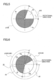
- the light path-switching disk 3 is configured of a rotatable disk for switching the light path in turn and includes a reflecting area 3a and a transmitting area 3b divided in a rotational direction, as shown in FIG. 2 .
- the light path-switching disk 3 is disposed at an angle (herein, 45 degrees to the optical axis) to an optical axis of the light-condensing lens 1c.
- the light path-switching disk 3 is, for example, as shown in FIG. 1 , driven to rotate by a stepping motor 4 of a driving source.
- numeral 4a represents a driving axis.
- a reflecting coat 3d is formed on the reflecting area 3a of the light path-switching disk 3 on the surface which receives the blue laser beam BP.
- a reflecting coat 3e is formed on the transmitting area 3b of the light path-switching disk 3 on the surface which receives the blue laser beam BP.
- a dispersing coat 3f is formed on the opposite surface to the reflecting coat 3e. The dispersing surface 3f is applied for reducing speckling of the laser beam BP.
- a rotating dispersing plate can be provided instead of providing the dispersing surface 3f on the light path-switching disk 3.
- the light path of the blue laser beam BP which is reflected by the reflecting area 3a is the path in which the blue laser beam BP is emitted from the light source section 1 which irradiates a phosphor 5.
- the phosphor 5 is configured from a rotatable disk.
- numeral 6 represents a stepping motor as a driving source for the phosphor.
- a fluorescent coat 5a is applied on the phosphor 5.
- the fluorescent coat 5a generates green fluorescence and red fluorescence which are different from the blue laser beam BP, by the irradiation of the blue laser beam BP emitted from the light source section 1.
- the deterioration of the fluorescent coat 5a due to the laser beam irradiating the same spot continuously for a long time can be prevented.
- the fluorescent coat 5a for example, a mixture of a fluorescent material which generates green fluorescence and a fluorescent material which generates red fluorescence by being excited through the irradiation of the blue laser beam is applied.
- a fluorescent material which generates green fluorescence for example, a fluorescent material which generates red fluorescence by being excited through the irradiation of the blue laser beam is applied.
- a fluorescent material having a characteristic of a fluorescence range over a wavelength of green and a wavelength of red can be used.
- a light-condensing lens 7, a dichroic mirror 8, and a light-condensing lens 9 are disposed in the light path in which the blue laser beam BP is reflected toward the phosphor 5.
- the light-condensing lens 7 concentrates the blue laser beam BP which is reflected by the reflecting area 3a and converts it into a parallel light flux BP" .
- the dichroic mirror 8 transmits the blue laser beam BP and guides it to the phosphor 5.
- the dichroic mirror 8 reflects fluorescent light of another color than blue and guides it to a color component-changing disk 10, as a color-changing section.
- the color-changing disk 10 switches the green fluorescence GP and the red fluorescence RP.
- the light-condensing lens 9 concentrates the parallel light flux BP" on the phosphor 5 in a spot form, concentrates the fluorescence emitted from the phosphor 5, and converts it into a parallel light flux LP'.
- a fluorescence YP is excited by light having each color emitted from the light source section 1.
- a light path in which a fluorescence YP passes towards the color-changing disk 10 through the light-condensing lens 9, the dichroic mirror 8, and the light-condensing lens 11 is formed.
- the light-condensing lens 11 is disposed between the dichroic mirror 8 and the color-changing disk 10.
- the fluorescence which is reflected by the dichroic mirror 8 is concentrated by the light-condensing lens 11 and irradiates to the color-changing disk 10.
- the color-changing disk 10 is disposed at an angle to the optical axis of the light-condensing lens 11.
- the color-changing disk 10 is configured of a rotatable disk for changing color in turn.
- a reflecting area 10a and a reflecting area 10b are formed to be divided in the rotating direction.
- the reflecting area 10a reflects the green fluorescence GP, absorbs the red fluorescence RP, or transmits the red fluorescence RP
- the reflecting area 10b reflects the red fluorescence RP and absorbs the green fluorescence GP or transmits the green fluorescence GP.
- the color-changing disk 10 is also driven to rotate by the stepping motor 12 as a driving source, for example.
- the color-changing disk 10 reflects both of green and red fluorescence GP and RP but it is not limited to the above. It can be configured to reflect one of fluorescence GP and fluorescence RP and transmit the other.
- numeral 12a represents the driving axis.
- the blue laser beam BP after passing through the transmitting area 3b passes through a light path in which the blue laser beam BP emitted from the light source section 1 irradiates an image-forming panel 13 as a conventional image-forming element (for example, a digital micromirror micro device DMD). That is, the light path is such that light having each color emitted from the light source section 1 passes towards the image-forming element.
- a conventional image-forming element for example, a digital micromirror micro device DMD
- a light-condensing lens 14 is disposed in the light path.
- the light-condensing lens 14 converts the blue laser beam BP which has transmitted through the light path-switching disk 3 into a parallel light flux BP", and guides the parallel light flux BP" to a dichroic mirror 15.
- a light-condensing lens 16 is disposed ahead of the passing direction of the green fluorescence GP and the red fluorescence RP which are reflected by the color-changing disk 10.
- the light-condensing lens 16 concentrates the green fluorescence GP and the red fluorescence RP, converts them into a parallel light flux LP", and guides it to the dichroic mirror 15.
- the dichroic mirror is disposed at an angle to the optical axis of the light-condensing lenses 14 and 16.
- the dichroic mirror 15 is disposed on the light path between the image-forming panel 13 and the color-changing disk 10.
- the dichroic mirror 15 concentrates the light path of the parallel light flux BP" as blue light and the light path of the parallel light flux LP" as green (or red) light and guides it to the image-forming panel 13, as a mirror for light-path concentrating.
- the parallel light fluxes BP" and LP" whose light paths are concentrated through the dichroic mirror 15 are concentrated by a light-condensing lens 17 and guided to the conventional light tunnel 18.
- the light tunnel 18 is an optical member for preventing the irregularity of light quantity which lowers the irregularity of light quantity.
- a fly-eye lens can be used instead of the light tunnel 18.
- the light which passes through the light tunnel 18 becomes a parallel light flux through a light-condensing lens 19.
- the light is reflected by a reflecting mirror 20 and guided to the image-forming panel 13.
- the image-forming panel 13 is, for example, controlled by a conventional image generation part GE, for example.
- the light having each color is reflected by the image-forming panel 13 and irradiates a screen S through a projecting lens 21. Thereby, a color image is enlarged and formed on the screen S.
- the light path-switching disk 3 and the color-changing disk 10 rotate in synchronization at the same rotational speed.
- an angle ⁇ B of the transmitting area 3b is determined to maintain the time tB (see FIG. 7 ) corresponding to the transmitting area 3b which transmits the laser beam BP having a blue component.
- An angle ⁇ GB of the reflecting area 3a has the remaining angle (360- ⁇ B).
- the laser beam BP passes through the transmitting area 3b of the light path-switching disk 3, the laser beam BP does not irradiate the phosphor 5, therefore, the phosphor 5 does not emit fluorescence.
- the laser beam BP While the blue laser beam BP is reflected by the reflecting area 3a, the laser beam BP irradiates the phosphor 5 and the phosphor 5 generates fluorescence.
- the time tGB in which the laser beam irradiates the phosphor 5 corresponds to the angle ⁇ GB of the reflecting area 3a.
- one of boundary lines q1 and q2 is determined to locate in the transmitting area 3b of the light path-switching member.
- the boundary lines q1 and q2 are the borderlines between the reflecting area 10a which reflects the green fluorescence GP and the reflecting area 10b which reflects the red fluorescence RP.
- boundary lines q1 and q2 are determined to locate in the place where it is capable of having the ratio of a time tG and tR which is required for irradiating the fluorescence GP and fluorescence RP.
- the boundary lines q1 and q2 are determined as described above, a wide setting range can be obtained for the position of the boundary q1 upon designing. Therefore, even if the angles of the reflecting areas 10a and 10b of the color-changing disk 10 are not determined accurately, the necessary time for generating the blue light B, green light G, and red light R can be obtained by regulating the rotation timing of the light path-switching disk 3 when assembling the projector, as shown in FIG. 7 .
- the light path-switching disk 3 is configured to rotate to change the light path periodically
- the color-changing disk 10 is configured to rotate to change colors periodically.
- the light path-switching disk 3 and the color-changing disk 10 can be configured to reciprocate periodically.
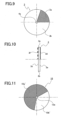
- FIG. 8 illustrates a modified example of the optical system according to Embodiment 1.
- the phosphor 5 is disposed in the transmitting light path in which the blue laser light BP which has transmitted through the transmitting area 3b of the light path-switching disk 3 travels.
- a dichroic mirror 15 is disposed in the reflecting light path in which the blue laser beam BP which is reflected by the reflecting area 3a of the light path-switching disk 3 travels.
- a light path in which the light emitted from the light source section 1 travels towards the image-forming element through the light-condensing lens 14 and the dichroic mirror 15 is disposed.
- the angle of the reflecting area 3a is similar to the angle of the transmitting area 3b shown in FIG. 2 .
- the angle of the transmitting area 3b is similar to the angle of the reflecting area 3a shown in FIG. 2 .
- a reflection-preventing coat 3e is formed on both surfaces of the transmitting area 3b of the light path-switching disk 3.
- a dispersing surface 3f is formed in the reflecting area 3a on the surface on which the laser beam BP irradiates and a reflection-preventing coat 3d is formed on the opposite surface.
- the color-changing disk 10 includes a transmitting area 10a' which transmits the green fluorescence GP and blocks the transmission of the red fluorescence RP, and a transmitting area 10b' which transmits the red fluorescence RP and blocks the transmission of the green fluorescence GP.
- the angle of the transmitting area 10a' is similar to the angle of the reflecting area 10a shown in FIG. 4
- the angle of the transmitting area 10b' is similar to the angle of the reflecting area 10b shown in FIG. 4 .
- the color-changing disk 10 is disposed in the direction which is perpendicular to the light path of the light-condensing lenses 11 and 16.
- a reflecting mirror 22 for turning the light path is disposed between the light-condensing lens 16 and the dichroic mirror 15.
- a reflecting mirror 23 for turning the light path is disposed between the light-condensing lens 19 and the reflecting mirror 20.
- the function of the optical system of the projector shown in FIG. 8 is similar to the function of the optical system of the projector as shown in FIG. 1 , so the description of the function is omitted herein.
- the phosphor 5 can be disposed on each of the transmitting light path and the reflecting light path of the laser beam BP in the light path-switching disk 3. Thereby, it is possible to have more choice in the layout of each of the optical elements.
- FIG. 12 is an optical view illustrating an optical system of a projector according to Embodiment 2 of the present invention.
- a dichroic mirror which transmits the blue laser beam BP and guides it to the light path-switching disk 3, and reflects the light of another color than blue and guides it to the color-changing disk 10 is disposed between the light path-switching disk 3 and the condensing lens 1c.
- a concave lens 1c' which converts the laser beam BP into the parallel light flux is disposed between the light-condensing lens 1c and the dichroic mirror 8.
- the light path-switching disk 3 includes a reflecting area 3a on which the fluorescent coat 5a is applied and a transmitting area 3b on which a fluorescent coat is not applied as illustrated in FIGs. 13, 14 .
- a reflection-preventing coat 3e is formed in the transmitting area 3b on the surface in which the laser beam BP irradiates.
- a light-condensing lens 9 is disposed between the dichroic mirror 8 and the light path-switching disk 3.
- the light-condensing lens 9 concentrates the parallel light flux of the laser beam BP on the light path-switching disk 3 in a spot form and concentrates the fluorescence generated through the reflecting area 3a of the light path-switching disk 3 and converts it into a parallel light flux.
- the laser beam BP which has transmitted through the transmitting area 3b of the light path-switching disk 3 becomes a parallel light flux through the light-condensing lens 9' and is guided to the dichroic mirror 15 through the reflecting mirrors for light-path turning 22' and 22.
- the fluorescence YP including the green fluorescence GP and red fluorescence RP which is generated through the reflecting area 3a of the light path-switching disk 3 is guided to the color-changing disk 10 through the dichroic mirror 8.
- the color-changing disk 10 is, as shown in FIG. 15 , configured of a rotatable disk for changing the color component in turn.
- the rotatable disk includes a transmitting area 10a' and a transmitting area 10b' which are divided with an angle to the rotational direction.
- the transmitting area 10a' transmits the green fluorescence GP and absorbs or reflects the red fluorescence RP and the transmitting area 10b' transmits the red fluorescence RP and absorbs or reflects the green fluorescence GP.
- the light-condensing lenses 11 and 16 are disposed between the dichroic mirror 8 and dichroic mirror 15.
- the color-changing disk 10 is disposed between the light-condensing lenses 11 and 16, and rotates on the plan perpendicular to the optical axis of the light-condensing lenses 11 and 16.
- Embodiment 2 a light path in which the color light emitted from the light source section 1 passes towards the image-forming element through the light-condensing lens 9', reflecting mirror 22', reflecting mirror 22, dichroic mirror 15, and the light-condensing lens 17' is formed.
- the phosphor 5 and the light path-switching disk 3 can be configured integrally so that the number of the driving sources as the driving element for rotation can be lowered, compared with Embodiment 1 and the modified example of Embodiment 1. Therefore, the optical element of the optical system can be simplified.
- the light-condensing lens 1c is disposed in the light source section 1 and the laser beam BP is concentrated on the light path-switching disk 3.
- the configurations are not always limited to the above.
- it can be configured such that the incident position of the laser beam BP which enters the coupling lens 1b is provided at the eccentric position from the center of the optical axis of the coupling lens and concentrates the light on the light path-switching disk 3 without providing the condensing lens 1c in the light source 1.
- the laser diode 1a and the coupling lens 1b can be disposed in a concentrating fashion so that the light is concentrated on the light path-switching disk 3.
- Various configurations can be applied for such an optical system which concentrates the light by using the laser diode 1a, coupling lens 1b and light-condensing lens 1c.
- the relationship between the transmission and reflection of the dichroic mirrors 8 and 15 can be determined freely according to the configurations of the optical system as long as it does not exceed the range of the purport of the present invention.
- the light source section 1 can be configured in only one variation so that the cooling configuration of the light source section 1 can be simplified.
- the phosphor 5 is also configured in one variation and it is unnecessary to divide a fluorescence area of the phosphor 5 in more than two variations. Thereby the phosphor 5 can be made simply. Consequently, it is possible to have more choice for the layout of each of the optical elements and to minimize the projector.
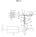
- FIG. 17 is an optical view which illustrates schematically the configuration of the optical system of a projector having a light source device according to Embodiment 3 of the present invention.
- FIG. 17 the same numerals and symbols are indicated for elements having similar configurations to Embodiment 1.
- a light source section 1 is configured of a laser diode 1a (LD), a coupling lens 1b, and a light-condensing lens 1c.
- LD laser diode
- coupling lens 1b coupling lens
- light-condensing lens 1c light-condensing lens
- a plurality of laser diodes 1a is disposed on a driving circuit board 2 and the coupling lens 1b is disposed on each laser diode 1a.
- a laser beam emitted from the laser diode 1a is concentrated through the coupling lens 1b and guided to the light-condensing lens 1c as a parallel light flux.
- the laser diode 1a emits blue laser beam BP.
- a light path-switching disk 3 which regularly switches the light path through which the color light is emitted from the light source section 1 passes is formed.
- the light path is switched between the light path where fluorescence excited by the blue light emitted from the light source section 1 passes and the light path where the blue light emitted from the light source section 1 passes towards an image-forming panel 13 as an image-forming element.
- a beam spot BSP is formed by the irradiation of the laser beam BP on the light path-switching disk 3.
- the light path-switching disk 3 includes a rotatable disk for switching the light path in turn.
- the rotatable disk includes a reflecting area 3a and a transmitting area 3b, which are divided in the rotational direction.
- the light path-switching disk 3 is disposed at an angle to the optical axis of the light-condensing lens 1c.
- the light path-switching disk 3 is driven to rotate by the stepping motor 4.
- the blue laser beam BP emitted from the light source section 1 passes towards a light tunnel 18.
- the blue laser beam BP irradiates the phosphor 5.
- a light-condensing lens 16', dichroic mirror 15' for light-path combining, and light-condensing lens 17' are disposed.
- a color-changing disk 10 is disposed between the light tunnel 18 and the light-condensing lens 17'.
- the color-changing disk 10 is equally divided into four segments.
- the dichroic mirror 15' transmits the blue laser beam BP and reflects fluorescence RP and GP generated through the phosphor 5.
- a light path in which the color laser beam BP emitted from the light source section 1 passes towards the image formation element through the light-condensing lens 16', dichroic mirror 15', and light-condensing lens 17' is disposed.
- the dichroic mirror 8' transmits the blue laser beam BP and reflects the fluorescence RP and GP.
- the fluorescence RP and GP which is reflected by the dichroic mirror 8' is reflected by the reflecting mirror 22' and guided to the dichroic mirror 15'.
- Embodiment 3 in the light path formed through the light-condensing lens 9', dichroic mirror 8', reflecting mirror 22', dichroic mirror 15', and light-condensing lens 17', the fluorescence RP and GP excited by the color light emitted from the light source section 1 passes towards the color-changing disk 10.
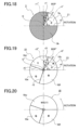
- the color-changing disk 10, as shown in FIG. 19 includes a transmitting area 10c, a transmitting area 10d, a transmitting area 10e and a transmitting area 10f.
- the transmitting area 10c transmits the laser beam BP and blocks transmission of both of fluorescence GP and RP
- the transmitting area 10d transmits yellow fluorescence YP (both of fluorescence GP and RP) and blocks transmission of the laser beam BP
- the transmitting area 10e transmits the fluorescence GP and blocks transmission of the laser beam BP and the fluorescence RP
- the transmitting area 10f transmits the fluorescence RP and blocks transmission of the laser beam BP and fluorescence GP.
- the transmitting areas 10c to 10f are configured from an arc-like area.
- the angle of the arc to the center O" of the arc-like area 10c is, for example, 75 degrees.
- the arc-like areas 10d to 10f are formed to have equal angles.
- the angle thereof to the center O" is, for example, 95 degrees.
- the laser beam BP is reflected when the reflecting area 3a of the light path-switching disk 3 crosses through the light path of the laser beam BP, and is guided to the transmitting area 10c of the color-changing disk 10 through the light-condensing lens 16', dichroic mirror 15', and light-condensing lens 17'.
- the laser beam BP is transmitted when the transmitting area 3b of the light path-switching disk 3 crosses the light path of the laser beam BP and is guided to the phosphor 5 through the light-condensing lens 7', dichroic mirror 8', and light-condensing lens 9'.
- the phosphor 5 is excited by the laser beam BP and generates the fluorescence RP and GP.
- the laser beam BP and fluorescence RP and GP are guided to the dichroic mirror 8' and the fluorescence RP and GP is reflected by the dichroic mirror 8'.
- the reflected fluorescence RP and GP is further reflected by the reflecting mirror 22' and guided to the dichroic mirror 15'.
- the light paths of the laser beam BP and fluorescence RP and GP are concentrated through the dichroic mirror 15'.
- the fluorescence RP and GP are guided to the transmitting areas 10d, 10e and 10f of the color-changing disk 10 through the light-condensing lens 17'.
- Each color light which has transmitted through each transmitting area 10c to 10f of the color-changing disk 10 is incident on the light tunnel 18.
- the distribution of the light amount of each color light is averaged during traveling in the light tunnel 18.
- Each color light emitted from the light tunnel 18 becomes a parallel light flux by the light-condensing lens 19.
- the light is reflected by the reflecting mirror 22 and guided to the image-forming panel 13.
- the image-forming panel 13 is controlled by the image generation part GE. Each color light is reflected by the image-forming panel 13 and irradiated to a screen S through the projector lens 21. Thereby, as shown in FIG. 19 , each color light having a B, R, G,Y component is formed while the color-changing disk 10 rotates one revolution and the color image is enlarged and displayed on the screen S.
- the color-changing disk 10 is disposed between the light tunnel 18 and the light-condensing lens 17' so that the light-condensing lens 17' can be used together with the light-condensing lens 11 for the color-changing disk.
- the light-condensing lens 17 originally provided in the optical system shown in FIG. 1 and the optical system shown in FIG. 8 is also used for the condensing lens 11. Thereby the simplification of the optical system can be achieved.
- the color-changing disk 10 is configured of the four segments of the transmitting areas 10c to 10f. However, the color-changing disk 10 is basically disposed in order to generate fluorescence RP and GP from the fluorescence YP.
- the fluorescence YP and the laser beam BP can be switched by the light path-switching disk 3. Accordingly, it is not necessary to switch the fluorescence YP and the laser beam BP by the color-changing disk 10.
- the fluorescence YP and the laser beam BP are generated separately to each other, the fluorescence GP and RP exists between the fluorescence YP and laser beam GP by the color-changing disk 10. Therefore, the number of segments of the color-changing disk 10 becomes four.
- the number of segments of the color-changing disk 10 can be reduced from 4 segments to 3 segments. Thereby, the number of manufacturing processes of the color-changing disk 10 can be reduced and cost reduction can be achieved.
- FIG. 20 illustrates an example of the three-segment color-changing disk 10.
- the color-changing disk 10 includes an arc-like area 10W configured of a cutout or a transparent area, an arc-like area 10e which transmits the fluorescence GP and blocks transmission of the laser beam BP and fluorescence RP, and an arc-like area 10f which transmits fluorescence RP and blocks transmission of the laser beam BP and fluorescence GP.
- the laser beam BP and fluorescence YP can be switched by the light path-switching disk 3 solely.
- the beam spots BSP and BSP' are formed on the light path-switching disk 3 and the color-changing disk 10.
- the beam spots BSP and BSP' have a predetermined size.
- the beam spot BSP straddles both of the reflecting area 3a and transmitting area 3b near the boundaries r1 and r2 which are between the reflecting area 3a and the transmitting area 3b of the light path-switching disk.
- the beam spot BSP' straddles the transmitting areas which are disposed adjacently to each other near the boundaries r3 to r6 between the transmitting areas 10c to 10f of the color-changing disk 10.
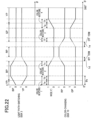
- FIG. 21 is a timing chart which schematically illustrates the relationship between the color mixture, the light path-switching disk 3, and the color-changing disk 10.
- the duration of the color mixing is decided according to the diameters of the BSP and BSP' provided that the rotation numbers of the light path-switching disk 3 and the color-changing disk 10 conform to each other and the rotation numbers per one unit of time remain constant.
- An angle which is formed by two tangential lines to the radial direction r1' and r1" is ⁇ s.
- the two tangential lines r1' and r1" pass through the rotation center O of the light path-switching disk 3 and have contact with the circle of the beam spot BSP.
- the rotation angle ⁇ of the light path-switching disk 3 is 0 degrees when the boundary r1 conforms to the tangential line in the radial direction r1'.
- the rotation angle ⁇ of the light path-switching disk 3 becomes the same angle as ⁇ s
- the boundary r1 becomes identical to the tangential line in the radial direction r1"
- the light amount of fluorescence YP which is guided to the color-changing disk 10 becomes zero.
- the light amount of the laser beam BP which is guided to the color-changing disk 10 becomes stable as 1.
- Color mixing occurs while the boundary r1 crosses the beam spot BSP.
- the above mixture is represented as mixture 1.
- the beam spot BSP is incident on only the reflecting area 3a of the light path-switching disk 3. Therefore, the light amount of the laser beam BP which is guided to the color-changing disk 10 remains stable as 1.
- the beam spot BSP is not incident on the reflecting area 3a of the light path-switching disk 3. Therefore, the light amount of the laser beam BP which is guided to the color-changing disk 10 becomes zero. On the other hand, the light amount of the fluorescence YP which is guided to the color-changing disk 10 becomes stable as 1. During the rotation of one revolution of the light path-switching disk 3, the above-described color mixtures 1 and 2 occur.
- the light path-switching disk 3 and the color-changing disk 10 rotate in synchronization in a state such that the rotational phases of the boundary r1 (boundary r2) and boundary r3 are conformable.
- the boundary r3 of the areas in the color-changing disk 10 and the boundary r1 of the areas in the light path-changing disk 3 correspond one by one and rotate to synchronize their own phases.
- the angle ⁇ 0 degrees.
- the fluorescence YP and laser beam BP start mixing and the color mixture 1 continues while the angle ⁇ of the color-changing disk 10 is between 0 to ⁇ s.
- the color mixture 1a occurs because the laser beam BP is merged to the fluorescence YP.
- the color mixture 1b occurs because the fluorescence YP is merged to the laser beam BP.
- the color-changing disk 10 rotates in the direction indicated with the arrow Z2 and the boundary r4 corresponds to the tangential line in the radius direction r3', only the laser beam BP is guided to the light tunnel 18. During the above term, because only the laser beam BP is guided to the light tunnel 18, color mixing by the color-changing disk 10 does not occur.
- the color mixture 1c occurs because the fluorescence RP is merged to the laser beam BP.
- a color mixture 1d occurs because the laser beam BP is merged to the fluorescence RP.
- the color mixture 1e occurs because the fluorescence GP is merged to the fluorescence RP.
- color mixing 1f occurs because the fluorescence RP is merged to the fluorescence GP.
- the color mixture of the fluorescence GP and fluorescence YP occurs.
- Such a mixture is represented as a color mixture 4.
- the color mixture 1g occurs because the fluorescence YP is merged to the fluorescence GP.
- the color mixture 1h occurs because the fluorescence GP is merged to the fluorescence YP.
- the laser diode (LD) 1a or the image-forming panel 13 is turned off during the projecting time in which the color mixture 1 to 4 occurs.
- the image becomes dark accordingly.
- Embodiment 3 in order to prevent the image becoming dark at minimum and to keep the color-reproduction range, the efforts described later are made.
- the illuminating efficiency of the laser beam BP is at the maximum because it is emitted from the light source section 1.
- the fluorescence YP is generated through the irradiation of the laser beam BP.
- the illuminating efficiency of the fluorescence YP is determined by the exciting efficiency of the phosphor 5 by the laser beam BP. Because there is a loss of light amount conversion in the phosphor 5, the illuminating efficiency of the fluorescence YP becomes lower than that of the laser beam BP.
- the laser beam BP includes a loss of light amount which is generated upon passing through the dichroic mirror 15'.
- the fluorescence YP, RP and GP include a loss of light amount upon being reflected by the dichroic mirror 8', reflecting mirror 22', and dichroic mirror 15'.
- the above loss of light amount is disregarded. However, even if such loss of light amount is disregarded, there is a loss of light amount which cannot be disregarded in the fluorescence RP and GP.
- the laser beam BP and fluorescence YP can be transmitted through the color-changing disk 10.
- the fluorescence RP and GP include a loss generated upon transmitting through the color-changing disk 10. Therefore, the illuminating efficiencies of the fluorescence RP and GP are much lower than that of the laser beam.
- the illuminating efficiency to the screen S becomes laser beam BP > fluorescence YP > fluorescence GP > fluorescence RP.
- the effect of the decrease of color reproducibility which is derived from color mixing in the fluorescence RP is the largest.
- Embodiment 3 as shown in FIG. 22 with the broken line, during the term in which the color mixture 1d and color mixture 1e occur, at least one of the laser diode 1a and the digital micromirror device DMD is turned off. Thereby, a bright projector can be achieved which can prevent the decrease of purity in color and the decrease of the color reproduction range.
- the illuminating efficiency of the fluorescence RP is the lowest.
- the fluorescence or the laser beam BP which has the lowest illumination efficiency, it is appropriate to configure such that the laser diode 1a or the digital micromirror device DMD is turned off during the term in which color mixing occurs.
- the laser diode 1a or the digital micromirror device DMD may be turned off during the term in which color mixing upon projecting light having each different colors occurs.
- the phase of the boundary r1 of the light path-switching disk 3 and the phase of the boundary r3 of the color-changing disk 10 rotate in synchronization.
- At least one of the laser diode 1a and the digital micromirror device can be turned off according to the larger diameter in the diameter ⁇ of the beam spot BSP of the light path-switching disk 3 and the diameter ⁇ ' of the beam spot BSP' of the color-changing disk 10. Thereby, the control of on-off can be simplified.
- Embodiment 4 it is described that the phosphor coat 5a which generates green fluorescence GP which is different from the laser beam BP and yellow fluorescence YP including the red fluorescence RP is applied to the phosphor 5.
- the phosphor coat 5a' which generates green fluorescence GP through the excitation of the laser beam BP or the phosphor coat 5a" which generates red fluorescence RP through the excitation of the laser beam BP can be applied on the phosphor 5.
- the fluorescent coats 5a' and 5a" can be applied during the term in which the green fluorescence GP is projected or the term in which the red fluorescence RP is projected.
- the color of the fluorescence GP can be controlled by cutting the fluorescence having a predetermined wavelength from the spectrum of the fluorescence GP.
- the purity in green color can be increased by cutting the light having a long wavelength from the fluorescence GP.
- a color image can be generated by using a single light source section without separating the fluorescence area of the phosphor into an area generating green fluorescence and an area generating red fluorescence.
Landscapes
- Physics & Mathematics (AREA)
- Engineering & Computer Science (AREA)
- General Physics & Mathematics (AREA)
- Multimedia (AREA)
- Optics & Photonics (AREA)
- Signal Processing (AREA)
- Spectroscopy & Molecular Physics (AREA)
- General Engineering & Computer Science (AREA)
- Astronomy & Astrophysics (AREA)
- Microelectronics & Electronic Packaging (AREA)
- Projection Apparatus (AREA)
- Non-Portable Lighting Devices Or Systems Thereof (AREA)
- Mechanical Light Control Or Optical Switches (AREA)
- Video Image Reproduction Devices For Color Tv Systems (AREA)
Applications Claiming Priority (4)
| Application Number | Priority Date | Filing Date | Title |
|---|---|---|---|
| JP2012282475 | 2012-12-26 | ||
| JP2013182894A JP5637274B2 (ja) | 2012-12-26 | 2013-09-04 | 光源装置及びこれを用いたプロジェクタ |
| PCT/JP2013/085309 WO2014104385A1 (en) | 2012-12-26 | 2013-12-24 | Light source device and projector using the same |
| EP13869826.1A EP2939070B1 (en) | 2012-12-26 | 2013-12-24 | Light source device and projector using the same |
Related Parent Applications (2)
| Application Number | Title | Priority Date | Filing Date |
|---|---|---|---|
| EP13869826.1A Division EP2939070B1 (en) | 2012-12-26 | 2013-12-24 | Light source device and projector using the same |
| EP13869826.1A Division-Into EP2939070B1 (en) | 2012-12-26 | 2013-12-24 | Light source device and projector using the same |
Publications (2)
| Publication Number | Publication Date |
|---|---|
| EP3703364A1 EP3703364A1 (en) | 2020-09-02 |
| EP3703364B1 true EP3703364B1 (en) | 2024-05-29 |
Family
ID=51021443
Family Applications (2)
| Application Number | Title | Priority Date | Filing Date |
|---|---|---|---|
| EP20171238.7A Active EP3703364B1 (en) | 2012-12-26 | 2013-12-24 | Color sequential light source for preventing color mixing and projector using the same |
| EP13869826.1A Active EP2939070B1 (en) | 2012-12-26 | 2013-12-24 | Light source device and projector using the same |
Family Applications After (1)
| Application Number | Title | Priority Date | Filing Date |
|---|---|---|---|
| EP13869826.1A Active EP2939070B1 (en) | 2012-12-26 | 2013-12-24 | Light source device and projector using the same |
Country Status (8)
| Country | Link |
|---|---|
| US (4) | US9726966B2 (enExample) |
| EP (2) | EP3703364B1 (enExample) |
| JP (1) | JP5637274B2 (enExample) |
| KR (1) | KR101787855B1 (enExample) |
| CN (2) | CN106125477B (enExample) |
| CA (1) | CA2896212C (enExample) |
| MX (1) | MX2015008204A (enExample) |
| WO (1) | WO2014104385A1 (enExample) |
Families Citing this family (32)
| Publication number | Priority date | Publication date | Assignee | Title |
|---|---|---|---|---|
| JP5637274B2 (ja) * | 2012-12-26 | 2014-12-10 | 株式会社リコー | 光源装置及びこれを用いたプロジェクタ |
| JP6476667B2 (ja) * | 2013-11-01 | 2019-03-06 | 株式会社リコー | 光源装置及びこれを用いたプロジェクタ |
| CN109557750B (zh) * | 2017-09-26 | 2021-06-15 | 中强光电股份有限公司 | 照明系统及使用照明系统的投影装置 |
| JP6815715B2 (ja) * | 2014-08-29 | 2021-01-20 | 日亜化学工業株式会社 | 光源装置及び該光源装置を備えたプロジェクタ |
| DE102014221382A1 (de) * | 2014-10-21 | 2016-04-21 | Osram Gmbh | Beleuchtungsvorrichtung mit Pumpstrahlungsquelle |
| JP6439391B2 (ja) * | 2014-11-06 | 2018-12-19 | 株式会社リコー | 光源装置及び投射表示装置 |
| JP6429300B2 (ja) * | 2015-04-24 | 2018-11-28 | Necディスプレイソリューションズ株式会社 | 投射型表示システム、投射型表示装置及びタイミング調整方法 |
| JP6206560B2 (ja) | 2015-09-28 | 2017-10-04 | 株式会社リコー | システム |
| JP6544520B2 (ja) * | 2015-10-09 | 2019-07-17 | セイコーエプソン株式会社 | 照明装置およびプロジェクター |
| CN107621744A (zh) * | 2016-07-13 | 2018-01-23 | 深圳市光峰光电技术有限公司 | 光源及投影仪 |
| CN106200235B (zh) * | 2016-07-22 | 2019-01-25 | 明基智能科技(上海)有限公司 | 投影机及应用其的投影方法 |
| JP6881919B2 (ja) * | 2016-09-08 | 2021-06-02 | キヤノン株式会社 | 画像投射装置 |
| CN108267913B (zh) * | 2016-12-30 | 2021-06-08 | 中强光电股份有限公司 | 光源模块以及投影装置 |
| JP2018159837A (ja) * | 2017-03-23 | 2018-10-11 | 株式会社ライトショー・テクノロジー | 光源装置および投射型表示装置 |
| WO2018198596A1 (ja) * | 2017-04-27 | 2018-11-01 | ソニー株式会社 | 画像表示装置、及び光源装置 |
| US11652963B2 (en) * | 2017-11-14 | 2023-05-16 | Signify Holding B.V. | Solid state light sources enabling spokes when used with a color wheel |
| CN110082998A (zh) * | 2018-01-25 | 2019-08-02 | 深圳光峰科技股份有限公司 | 激光合光装置及显示设备 |
| CN110471245B (zh) * | 2018-05-10 | 2021-10-22 | 深圳光峰科技股份有限公司 | 光源系统、投影设备及照明设备 |
| KR102655480B1 (ko) * | 2019-01-22 | 2024-04-08 | 엘지전자 주식회사 | 프로젝터 |
| JP7268421B2 (ja) | 2019-03-18 | 2023-05-08 | 株式会社リコー | 光源光学系、光源装置及び画像投射装置 |
| JP2020153798A (ja) | 2019-03-19 | 2020-09-24 | 株式会社リコー | 光学装置、測距光学系ユニット、測距装置及び測距システム |
| CN111722465A (zh) | 2019-03-20 | 2020-09-29 | 株式会社理光 | 光源装置、图像投影装置和光源光学系统 |
| CN111856859B (zh) * | 2019-04-24 | 2023-03-10 | 深圳光峰科技股份有限公司 | 光源系统及显示装置 |
| JP7434808B2 (ja) | 2019-11-01 | 2024-02-21 | 株式会社リコー | 光源装置及び画像投射装置 |
| US12066752B2 (en) | 2019-11-01 | 2024-08-20 | Ricoh Company, Ltd. | Light-source device, image projection apparatus, and light-source optical system |
| CN110716380B (zh) * | 2019-11-25 | 2021-05-18 | 成都极米科技股份有限公司 | 一种光源系统及投影机 |
| JP7567403B2 (ja) | 2020-11-27 | 2024-10-16 | 株式会社リコー | 光源装置、画像投射装置および光源光学系 |
| US11720010B2 (en) | 2020-12-07 | 2023-08-08 | Ricoh Company, Ltd. | Light source device and projection device |
| JP7625913B2 (ja) | 2021-03-17 | 2025-02-04 | 株式会社リコー | 光源装置及び画像投射装置 |
| US11874591B2 (en) | 2021-03-23 | 2024-01-16 | Casio Computer Co., Ltd. | Light source apparatus, projection apparatus and color wheel device |
| CN214474391U (zh) * | 2021-04-29 | 2021-10-22 | 中强光电股份有限公司 | 照明系统及投影装置 |
| US11953816B2 (en) | 2021-08-06 | 2024-04-09 | Ricoh Company, Ltd. | Wavelength conversion plate, light source device, and image projection apparatus |
Family Cites Families (41)
| Publication number | Priority date | Publication date | Assignee | Title |
|---|---|---|---|---|
| JPS4711154Y1 (enExample) | 1968-12-20 | 1972-04-25 | ||
| JP2003295316A (ja) | 2002-04-05 | 2003-10-15 | Matsushita Electric Ind Co Ltd | 表示装置及び投写型表示装置 |
| JP4117551B2 (ja) * | 2003-06-05 | 2008-07-16 | ミネベア株式会社 | カラーホイール、その製造方法、およびそれを備えた分光装置並びに画像表示装置 |
| JP2006189485A (ja) * | 2004-12-28 | 2006-07-20 | Phoenix Denki Kk | 直流点灯の高圧放電灯による投射型システムとその作動方法 |
| JP2008145508A (ja) | 2006-12-06 | 2008-06-26 | Mitsubishi Electric Corp | 表示装置 |
| US8194192B2 (en) | 2006-12-06 | 2012-06-05 | Mitsubishi Electric Corporation | Projection display |
| TWI392954B (zh) * | 2009-05-11 | 2013-04-11 | Coretronic Corp | 照明系統及照明控制方法 |
| JP4742349B2 (ja) | 2009-06-30 | 2011-08-10 | カシオ計算機株式会社 | 光源装置及びプロジェクタ |
| JP4711154B2 (ja) * | 2009-06-30 | 2011-06-29 | カシオ計算機株式会社 | 光源装置及びプロジェクタ |
| JP5495023B2 (ja) | 2009-12-21 | 2014-05-21 | カシオ計算機株式会社 | 光源ユニット及びプロジェクタ |
| JP5567844B2 (ja) | 2010-01-29 | 2014-08-06 | 日立コンシューマエレクトロニクス株式会社 | 投写型映像表示装置 |
| JP5671666B2 (ja) * | 2010-02-12 | 2015-02-18 | 日立マクセル株式会社 | 固体光源装置及び投射型表示装置 |
| JP5494053B2 (ja) | 2010-03-16 | 2014-05-14 | セイコーエプソン株式会社 | プロジェクター |
| JP5617288B2 (ja) | 2010-03-18 | 2014-11-05 | セイコーエプソン株式会社 | 照明装置及びプロジェクター |
| JP2012053162A (ja) * | 2010-08-31 | 2012-03-15 | Sanyo Electric Co Ltd | 投写型映像表示装置 |
| JP5673119B2 (ja) | 2011-01-18 | 2015-02-18 | セイコーエプソン株式会社 | 光源装置及びプロジェクター |
| TWI427397B (zh) | 2011-03-23 | 2014-02-21 | 台達電子工業股份有限公司 | 光源系統 |
| JP5842162B2 (ja) * | 2011-03-23 | 2016-01-13 | パナソニックIpマネジメント株式会社 | 光源装置及びそれを用いた画像表示装置 |
| KR20120113115A (ko) | 2011-04-04 | 2012-10-12 | 엘지전자 주식회사 | 광원 장치 및 그 제조 방법 |
| JP5987368B2 (ja) * | 2011-07-05 | 2016-09-07 | 株式会社リコー | 照明装置および投射装置 |
| JP5987382B2 (ja) * | 2011-07-22 | 2016-09-07 | 株式会社リコー | 照明装置、ならびに、投射装置および投射装置の制御方法 |
| US9467667B2 (en) * | 2011-09-09 | 2016-10-11 | Appotroincs Corporation Limited | Method and apparatus of white balance adjustment |
| CN103034035A (zh) * | 2011-09-30 | 2013-04-10 | 中强光电股份有限公司 | 照明系统与投影装置 |
| CN102645825B (zh) | 2011-11-03 | 2014-12-31 | 深圳市光峰光电技术有限公司 | 一种投影装置、光源系统以及色轮组件 |
| US8616705B2 (en) * | 2011-11-04 | 2013-12-31 | Appotronics (China) Corporation | Light source device and projection display method |
| CN102650813B (zh) | 2011-11-28 | 2015-02-04 | 深圳市光峰光电技术有限公司 | 光源系统、投影装置及其色平衡调整方法 |
| CN102520569A (zh) * | 2011-12-02 | 2012-06-27 | 深圳市光峰光电技术有限公司 | 光源装置及使用该光源装置的投影装置 |
| JP2013182894A (ja) | 2012-02-29 | 2013-09-12 | Oki Electric Ind Co Ltd | 光素子 |
| CN102720986B (zh) * | 2012-03-30 | 2014-08-13 | 深圳市光峰光电技术有限公司 | 发光装置及其投影系统与舞台灯系统 |
| JP6171345B2 (ja) * | 2012-09-10 | 2017-08-02 | 株式会社リコー | 照明光源装置及びこの照明光源装置を備えた投射装置及び投射装置の制御方法 |
| JP6056293B2 (ja) * | 2012-09-12 | 2017-01-11 | 株式会社リコー | 照明光源装置及びこの照明光源装置を備えた投射装置及び投射装置の制御方法 |
| JP5637274B2 (ja) * | 2012-12-26 | 2014-12-10 | 株式会社リコー | 光源装置及びこれを用いたプロジェクタ |
| JP6205835B2 (ja) * | 2013-05-14 | 2017-10-04 | 株式会社リコー | 照明装置、この照明装置を備えた投射装置、および、照明方法 |
| JP6233572B2 (ja) * | 2013-11-05 | 2017-11-22 | パナソニックIpマネジメント株式会社 | 照明装置 |
| US20150215569A1 (en) * | 2014-01-29 | 2015-07-30 | Wavien, Inc. | Projector with light source including laser, phosphor, and led |
| US10732495B2 (en) * | 2014-05-02 | 2020-08-04 | Coretronic Corporation | Illumination system, projection apparatus and method for driving illumination system |
| US10031405B2 (en) * | 2014-06-12 | 2018-07-24 | Nec Display Solutions, Ltd. | Light source device and projector with reducing optical system having adjustable position for positive power lens |
| US9554101B2 (en) * | 2014-12-28 | 2017-01-24 | Texas Instruments Incorporated | Shared-path illumination and excitation optics apparatus and systems |
| WO2016166885A1 (ja) * | 2015-04-17 | 2016-10-20 | Necディスプレイソリューションズ株式会社 | プロジェクタおよび画像表示方法 |
| JP6759853B2 (ja) * | 2016-08-22 | 2020-09-23 | 株式会社リコー | 照明装置、画像投射装置 |
| JP2018136506A (ja) * | 2017-02-23 | 2018-08-30 | 株式会社リコー | 照明装置、画像投射装置 |
-
2013
- 2013-09-04 JP JP2013182894A patent/JP5637274B2/ja active Active
- 2013-12-24 CN CN201610633465.XA patent/CN106125477B/zh active Active
- 2013-12-24 EP EP20171238.7A patent/EP3703364B1/en active Active
- 2013-12-24 EP EP13869826.1A patent/EP2939070B1/en active Active
- 2013-12-24 WO PCT/JP2013/085309 patent/WO2014104385A1/en not_active Ceased
- 2013-12-24 CA CA2896212A patent/CA2896212C/en active Active
- 2013-12-24 MX MX2015008204A patent/MX2015008204A/es not_active Application Discontinuation
- 2013-12-24 CN CN201380068102.0A patent/CN104871085B/zh active Active
- 2013-12-24 KR KR1020157020309A patent/KR101787855B1/ko active Active
- 2013-12-24 US US14/648,823 patent/US9726966B2/en active Active
-
2017
- 2017-06-29 US US15/638,161 patent/US10191361B2/en active Active
-
2018
- 2018-12-27 US US16/233,954 patent/US10627711B2/en active Active
-
2020
- 2020-03-02 US US16/806,584 patent/US11402737B2/en active Active
Also Published As
| Publication number | Publication date |
|---|---|
| CN104871085A (zh) | 2015-08-26 |
| US20170299953A1 (en) | 2017-10-19 |
| US11402737B2 (en) | 2022-08-02 |
| CA2896212C (en) | 2017-09-19 |
| EP3703364A1 (en) | 2020-09-02 |
| US10191361B2 (en) | 2019-01-29 |
| EP2939070B1 (en) | 2020-06-03 |
| EP2939070A4 (en) | 2016-02-17 |
| CN104871085B (zh) | 2016-09-14 |
| CN106125477B (zh) | 2018-09-28 |
| CN106125477A (zh) | 2016-11-16 |
| US20200201158A1 (en) | 2020-06-25 |
| EP2939070A1 (en) | 2015-11-04 |
| MX2015008204A (es) | 2015-09-16 |
| KR20150100895A (ko) | 2015-09-02 |
| US20150316840A1 (en) | 2015-11-05 |
| US9726966B2 (en) | 2017-08-08 |
| JP2014142588A (ja) | 2014-08-07 |
| US10627711B2 (en) | 2020-04-21 |
| JP5637274B2 (ja) | 2014-12-10 |
| KR101787855B1 (ko) | 2017-10-18 |
| WO2014104385A1 (en) | 2014-07-03 |
| CA2896212A1 (en) | 2014-07-03 |
| US20190129288A1 (en) | 2019-05-02 |
Similar Documents
| Publication | Publication Date | Title |
|---|---|---|
| US11402737B2 (en) | Light source device and projector including a phosphor and a color-changing section | |
| US9897900B2 (en) | Light source system and related projection system | |
| JP6743938B2 (ja) | 光源装置及びこれを用いたプロジェクタ | |
| JP2017146526A (ja) | 蛍光ホイール、光源装置およびプロジェクタ | |
| JP7788044B2 (ja) | 投写型映像表示装置 |
Legal Events
| Date | Code | Title | Description |
|---|---|---|---|
| PUAI | Public reference made under article 153(3) epc to a published international application that has entered the european phase |
Free format text: ORIGINAL CODE: 0009012 |
|
| STAA | Information on the status of an ep patent application or granted ep patent |
Free format text: STATUS: REQUEST FOR EXAMINATION WAS MADE |
|
| 17P | Request for examination filed |
Effective date: 20200424 |
|
| AC | Divisional application: reference to earlier application |
Ref document number: 2939070 Country of ref document: EP Kind code of ref document: P |
|
| AK | Designated contracting states |
Kind code of ref document: A1 Designated state(s): AL AT BE BG CH CY CZ DE DK EE ES FI FR GB GR HR HU IE IS IT LI LT LU LV MC MK MT NL NO PL PT RO RS SE SI SK SM TR |
|
| STAA | Information on the status of an ep patent application or granted ep patent |
Free format text: STATUS: EXAMINATION IS IN PROGRESS |
|
| 17Q | First examination report despatched |
Effective date: 20220309 |
|
| GRAJ | Information related to disapproval of communication of intention to grant by the applicant or resumption of examination proceedings by the epo deleted |
Free format text: ORIGINAL CODE: EPIDOSDIGR1 |
|
| STAA | Information on the status of an ep patent application or granted ep patent |
Free format text: STATUS: GRANT OF PATENT IS INTENDED |
|
| GRAP | Despatch of communication of intention to grant a patent |
Free format text: ORIGINAL CODE: EPIDOSNIGR1 |
|
| RIC1 | Information provided on ipc code assigned before grant |
Ipc: G02B 26/00 20060101ALN20231215BHEP Ipc: G03B 21/14 20060101ALI20231215BHEP Ipc: H04N 9/31 20060101AFI20231215BHEP |
|
| RIC1 | Information provided on ipc code assigned before grant |
Ipc: G02B 26/00 20060101ALN20240111BHEP Ipc: G03B 21/14 20060101ALI20240111BHEP Ipc: H04N 9/31 20060101AFI20240111BHEP |
|
| INTG | Intention to grant announced |
Effective date: 20240122 |
|
| GRAS | Grant fee paid |
Free format text: ORIGINAL CODE: EPIDOSNIGR3 |
|
| GRAA | (expected) grant |
Free format text: ORIGINAL CODE: 0009210 |
|
| STAA | Information on the status of an ep patent application or granted ep patent |
Free format text: STATUS: THE PATENT HAS BEEN GRANTED |
|
| P01 | Opt-out of the competence of the unified patent court (upc) registered |
Effective date: 20240404 |
|
| AC | Divisional application: reference to earlier application |
Ref document number: 2939070 Country of ref document: EP Kind code of ref document: P |
|
| AK | Designated contracting states |
Kind code of ref document: B1 Designated state(s): AL AT BE BG CH CY CZ DE DK EE ES FI FR GB GR HR HU IE IS IT LI LT LU LV MC MK MT NL NO PL PT RO RS SE SI SK SM TR |
|
| REG | Reference to a national code |
Ref country code: CH Ref legal event code: EP |
|
| REG | Reference to a national code |
Ref country code: IE Ref legal event code: FG4D |
|
| REG | Reference to a national code |
Ref country code: DE Ref legal event code: R096 Ref document number: 602013085771 Country of ref document: DE |
|
| REG | Reference to a national code |
Ref country code: LT Ref legal event code: MG9D |
|
| REG | Reference to a national code |
Ref country code: NL Ref legal event code: MP Effective date: 20240529 |
|
| PG25 | Lapsed in a contracting state [announced via postgrant information from national office to epo] |
Ref country code: IS Free format text: LAPSE BECAUSE OF FAILURE TO SUBMIT A TRANSLATION OF THE DESCRIPTION OR TO PAY THE FEE WITHIN THE PRESCRIBED TIME-LIMIT Effective date: 20240929 |
|
| PG25 | Lapsed in a contracting state [announced via postgrant information from national office to epo] |
Ref country code: BG Free format text: LAPSE BECAUSE OF FAILURE TO SUBMIT A TRANSLATION OF THE DESCRIPTION OR TO PAY THE FEE WITHIN THE PRESCRIBED TIME-LIMIT Effective date: 20240529 |
|
| PG25 | Lapsed in a contracting state [announced via postgrant information from national office to epo] |
Ref country code: FI Free format text: LAPSE BECAUSE OF FAILURE TO SUBMIT A TRANSLATION OF THE DESCRIPTION OR TO PAY THE FEE WITHIN THE PRESCRIBED TIME-LIMIT Effective date: 20240529 Ref country code: HR Free format text: LAPSE BECAUSE OF FAILURE TO SUBMIT A TRANSLATION OF THE DESCRIPTION OR TO PAY THE FEE WITHIN THE PRESCRIBED TIME-LIMIT Effective date: 20240529 |
|
| PG25 | Lapsed in a contracting state [announced via postgrant information from national office to epo] |
Ref country code: GR Free format text: LAPSE BECAUSE OF FAILURE TO SUBMIT A TRANSLATION OF THE DESCRIPTION OR TO PAY THE FEE WITHIN THE PRESCRIBED TIME-LIMIT Effective date: 20240830 |
|
| REG | Reference to a national code |
Ref country code: AT Ref legal event code: MK05 Ref document number: 1691576 Country of ref document: AT Kind code of ref document: T Effective date: 20240529 |
|
| PG25 | Lapsed in a contracting state [announced via postgrant information from national office to epo] |
Ref country code: ES Free format text: LAPSE BECAUSE OF FAILURE TO SUBMIT A TRANSLATION OF THE DESCRIPTION OR TO PAY THE FEE WITHIN THE PRESCRIBED TIME-LIMIT Effective date: 20240529 |
|
| PG25 | Lapsed in a contracting state [announced via postgrant information from national office to epo] |
Ref country code: AT Free format text: LAPSE BECAUSE OF FAILURE TO SUBMIT A TRANSLATION OF THE DESCRIPTION OR TO PAY THE FEE WITHIN THE PRESCRIBED TIME-LIMIT Effective date: 20240529 |
|
| PG25 | Lapsed in a contracting state [announced via postgrant information from national office to epo] |
Ref country code: PL Free format text: LAPSE BECAUSE OF FAILURE TO SUBMIT A TRANSLATION OF THE DESCRIPTION OR TO PAY THE FEE WITHIN THE PRESCRIBED TIME-LIMIT Effective date: 20240529 |
|
| PG25 | Lapsed in a contracting state [announced via postgrant information from national office to epo] |
Ref country code: LV Free format text: LAPSE BECAUSE OF FAILURE TO SUBMIT A TRANSLATION OF THE DESCRIPTION OR TO PAY THE FEE WITHIN THE PRESCRIBED TIME-LIMIT Effective date: 20240529 |
|
| PG25 | Lapsed in a contracting state [announced via postgrant information from national office to epo] |
Ref country code: PL Free format text: LAPSE BECAUSE OF FAILURE TO SUBMIT A TRANSLATION OF THE DESCRIPTION OR TO PAY THE FEE WITHIN THE PRESCRIBED TIME-LIMIT Effective date: 20240529 Ref country code: NO Free format text: LAPSE BECAUSE OF FAILURE TO SUBMIT A TRANSLATION OF THE DESCRIPTION OR TO PAY THE FEE WITHIN THE PRESCRIBED TIME-LIMIT Effective date: 20240829 Ref country code: LV Free format text: LAPSE BECAUSE OF FAILURE TO SUBMIT A TRANSLATION OF THE DESCRIPTION OR TO PAY THE FEE WITHIN THE PRESCRIBED TIME-LIMIT Effective date: 20240529 Ref country code: IS Free format text: LAPSE BECAUSE OF FAILURE TO SUBMIT A TRANSLATION OF THE DESCRIPTION OR TO PAY THE FEE WITHIN THE PRESCRIBED TIME-LIMIT Effective date: 20240929 Ref country code: HR Free format text: LAPSE BECAUSE OF FAILURE TO SUBMIT A TRANSLATION OF THE DESCRIPTION OR TO PAY THE FEE WITHIN THE PRESCRIBED TIME-LIMIT Effective date: 20240529 Ref country code: GR Free format text: LAPSE BECAUSE OF FAILURE TO SUBMIT A TRANSLATION OF THE DESCRIPTION OR TO PAY THE FEE WITHIN THE PRESCRIBED TIME-LIMIT Effective date: 20240830 Ref country code: FI Free format text: LAPSE BECAUSE OF FAILURE TO SUBMIT A TRANSLATION OF THE DESCRIPTION OR TO PAY THE FEE WITHIN THE PRESCRIBED TIME-LIMIT Effective date: 20240529 Ref country code: ES Free format text: LAPSE BECAUSE OF FAILURE TO SUBMIT A TRANSLATION OF THE DESCRIPTION OR TO PAY THE FEE WITHIN THE PRESCRIBED TIME-LIMIT Effective date: 20240529 Ref country code: BG Free format text: LAPSE BECAUSE OF FAILURE TO SUBMIT A TRANSLATION OF THE DESCRIPTION OR TO PAY THE FEE WITHIN THE PRESCRIBED TIME-LIMIT Effective date: 20240529 Ref country code: AT Free format text: LAPSE BECAUSE OF FAILURE TO SUBMIT A TRANSLATION OF THE DESCRIPTION OR TO PAY THE FEE WITHIN THE PRESCRIBED TIME-LIMIT Effective date: 20240529 Ref country code: RS Free format text: LAPSE BECAUSE OF FAILURE TO SUBMIT A TRANSLATION OF THE DESCRIPTION OR TO PAY THE FEE WITHIN THE PRESCRIBED TIME-LIMIT Effective date: 20240829 |
|
| PG25 | Lapsed in a contracting state [announced via postgrant information from national office to epo] |
Ref country code: NL Free format text: LAPSE BECAUSE OF FAILURE TO SUBMIT A TRANSLATION OF THE DESCRIPTION OR TO PAY THE FEE WITHIN THE PRESCRIBED TIME-LIMIT Effective date: 20240529 |
|
| PG25 | Lapsed in a contracting state [announced via postgrant information from national office to epo] |
Ref country code: NL Free format text: LAPSE BECAUSE OF FAILURE TO SUBMIT A TRANSLATION OF THE DESCRIPTION OR TO PAY THE FEE WITHIN THE PRESCRIBED TIME-LIMIT Effective date: 20240529 |
|
| PGFP | Annual fee paid to national office [announced via postgrant information from national office to epo] |
Ref country code: DE Payment date: 20241210 Year of fee payment: 12 |
|
| PG25 | Lapsed in a contracting state [announced via postgrant information from national office to epo] |
Ref country code: DK Free format text: LAPSE BECAUSE OF FAILURE TO SUBMIT A TRANSLATION OF THE DESCRIPTION OR TO PAY THE FEE WITHIN THE PRESCRIBED TIME-LIMIT Effective date: 20240529 |
|
| PGFP | Annual fee paid to national office [announced via postgrant information from national office to epo] |
Ref country code: GB Payment date: 20241226 Year of fee payment: 12 |
|
| PGFP | Annual fee paid to national office [announced via postgrant information from national office to epo] |
Ref country code: FR Payment date: 20241224 Year of fee payment: 12 |
|
| PG25 | Lapsed in a contracting state [announced via postgrant information from national office to epo] |
Ref country code: EE Free format text: LAPSE BECAUSE OF FAILURE TO SUBMIT A TRANSLATION OF THE DESCRIPTION OR TO PAY THE FEE WITHIN THE PRESCRIBED TIME-LIMIT Effective date: 20240529 |
|
| PG25 | Lapsed in a contracting state [announced via postgrant information from national office to epo] |
Ref country code: CZ Free format text: LAPSE BECAUSE OF FAILURE TO SUBMIT A TRANSLATION OF THE DESCRIPTION OR TO PAY THE FEE WITHIN THE PRESCRIBED TIME-LIMIT Effective date: 20240529 |
|
| PG25 | Lapsed in a contracting state [announced via postgrant information from national office to epo] |
Ref country code: SK Free format text: LAPSE BECAUSE OF FAILURE TO SUBMIT A TRANSLATION OF THE DESCRIPTION OR TO PAY THE FEE WITHIN THE PRESCRIBED TIME-LIMIT Effective date: 20240529 Ref country code: RO Free format text: LAPSE BECAUSE OF FAILURE TO SUBMIT A TRANSLATION OF THE DESCRIPTION OR TO PAY THE FEE WITHIN THE PRESCRIBED TIME-LIMIT Effective date: 20240529 |
|
| PG25 | Lapsed in a contracting state [announced via postgrant information from national office to epo] |
Ref country code: SM Free format text: LAPSE BECAUSE OF FAILURE TO SUBMIT A TRANSLATION OF THE DESCRIPTION OR TO PAY THE FEE WITHIN THE PRESCRIBED TIME-LIMIT Effective date: 20240529 |
|
| PG25 | Lapsed in a contracting state [announced via postgrant information from national office to epo] |
Ref country code: SM Free format text: LAPSE BECAUSE OF FAILURE TO SUBMIT A TRANSLATION OF THE DESCRIPTION OR TO PAY THE FEE WITHIN THE PRESCRIBED TIME-LIMIT Effective date: 20240529 Ref country code: SK Free format text: LAPSE BECAUSE OF FAILURE TO SUBMIT A TRANSLATION OF THE DESCRIPTION OR TO PAY THE FEE WITHIN THE PRESCRIBED TIME-LIMIT Effective date: 20240529 Ref country code: RO Free format text: LAPSE BECAUSE OF FAILURE TO SUBMIT A TRANSLATION OF THE DESCRIPTION OR TO PAY THE FEE WITHIN THE PRESCRIBED TIME-LIMIT Effective date: 20240529 Ref country code: EE Free format text: LAPSE BECAUSE OF FAILURE TO SUBMIT A TRANSLATION OF THE DESCRIPTION OR TO PAY THE FEE WITHIN THE PRESCRIBED TIME-LIMIT Effective date: 20240529 Ref country code: DK Free format text: LAPSE BECAUSE OF FAILURE TO SUBMIT A TRANSLATION OF THE DESCRIPTION OR TO PAY THE FEE WITHIN THE PRESCRIBED TIME-LIMIT Effective date: 20240529 Ref country code: CZ Free format text: LAPSE BECAUSE OF FAILURE TO SUBMIT A TRANSLATION OF THE DESCRIPTION OR TO PAY THE FEE WITHIN THE PRESCRIBED TIME-LIMIT Effective date: 20240529 |
|
| PG25 | Lapsed in a contracting state [announced via postgrant information from national office to epo] |
Ref country code: IT Free format text: LAPSE BECAUSE OF FAILURE TO SUBMIT A TRANSLATION OF THE DESCRIPTION OR TO PAY THE FEE WITHIN THE PRESCRIBED TIME-LIMIT Effective date: 20240529 |
|
| REG | Reference to a national code |
Ref country code: DE Ref legal event code: R097 Ref document number: 602013085771 Country of ref document: DE |
|
| PLBE | No opposition filed within time limit |
Free format text: ORIGINAL CODE: 0009261 |
|
| STAA | Information on the status of an ep patent application or granted ep patent |
Free format text: STATUS: NO OPPOSITION FILED WITHIN TIME LIMIT |
|
| PG25 | Lapsed in a contracting state [announced via postgrant information from national office to epo] |
Ref country code: SI Free format text: LAPSE BECAUSE OF FAILURE TO SUBMIT A TRANSLATION OF THE DESCRIPTION OR TO PAY THE FEE WITHIN THE PRESCRIBED TIME-LIMIT Effective date: 20240529 |
|
| 26N | No opposition filed |
Effective date: 20250303 |
|
| PG25 | Lapsed in a contracting state [announced via postgrant information from national office to epo] |
Ref country code: MC Free format text: LAPSE BECAUSE OF FAILURE TO SUBMIT A TRANSLATION OF THE DESCRIPTION OR TO PAY THE FEE WITHIN THE PRESCRIBED TIME-LIMIT Effective date: 20240529 |
|
| REG | Reference to a national code |
Ref country code: CH Ref legal event code: PL |
|
| PG25 | Lapsed in a contracting state [announced via postgrant information from national office to epo] |
Ref country code: LU Free format text: LAPSE BECAUSE OF NON-PAYMENT OF DUE FEES Effective date: 20241224 |
|
| PG25 | Lapsed in a contracting state [announced via postgrant information from national office to epo] |
Ref country code: SE Free format text: LAPSE BECAUSE OF FAILURE TO SUBMIT A TRANSLATION OF THE DESCRIPTION OR TO PAY THE FEE WITHIN THE PRESCRIBED TIME-LIMIT Effective date: 20240529 |
|
| REG | Reference to a national code |
Ref country code: BE Ref legal event code: MM Effective date: 20241231 |
|
| PG25 | Lapsed in a contracting state [announced via postgrant information from national office to epo] |
Ref country code: BE Free format text: LAPSE BECAUSE OF NON-PAYMENT OF DUE FEES Effective date: 20241231 |
|
| PG25 | Lapsed in a contracting state [announced via postgrant information from national office to epo] |
Ref country code: CH Free format text: LAPSE BECAUSE OF NON-PAYMENT OF DUE FEES Effective date: 20241231 |
|
| PG25 | Lapsed in a contracting state [announced via postgrant information from national office to epo] |
Ref country code: IE Free format text: LAPSE BECAUSE OF NON-PAYMENT OF DUE FEES Effective date: 20241224 |