EP3703347A1 - Mit sensor ausgestattete anzeigevorrichtung und elektronische vorrichtung - Google Patents
Mit sensor ausgestattete anzeigevorrichtung und elektronische vorrichtung Download PDFInfo
- Publication number
- EP3703347A1 EP3703347A1 EP20155934.1A EP20155934A EP3703347A1 EP 3703347 A1 EP3703347 A1 EP 3703347A1 EP 20155934 A EP20155934 A EP 20155934A EP 3703347 A1 EP3703347 A1 EP 3703347A1
- Authority
- EP
- European Patent Office
- Prior art keywords
- sensor
- display screen
- light
- display apparatus
- transparent
- Prior art date
- Legal status (The legal status is an assumption and is not a legal conclusion. Google has not performed a legal analysis and makes no representation as to the accuracy of the status listed.)
- Granted
Links
Images







Classifications
-
- H—ELECTRICITY
- H04—ELECTRIC COMMUNICATION TECHNIQUE
- H04M—TELEPHONIC COMMUNICATION
- H04M1/00—Substation equipment, e.g. for use by subscribers
- H04M1/02—Constructional features of telephone sets
- H04M1/0202—Portable telephone sets, e.g. cordless phones, mobile phones or bar type handsets
- H04M1/026—Details of the structure or mounting of specific components
- H04M1/0264—Details of the structure or mounting of specific components for a camera module assembly
-
- H—ELECTRICITY
- H04—ELECTRIC COMMUNICATION TECHNIQUE
- H04M—TELEPHONIC COMMUNICATION
- H04M1/00—Substation equipment, e.g. for use by subscribers
- H04M1/02—Constructional features of telephone sets
- H04M1/0202—Portable telephone sets, e.g. cordless phones, mobile phones or bar type handsets
- H04M1/026—Details of the structure or mounting of specific components
- H04M1/0266—Details of the structure or mounting of specific components for a display module assembly
-
- H—ELECTRICITY
- H04—ELECTRIC COMMUNICATION TECHNIQUE
- H04N—PICTORIAL COMMUNICATION, e.g. TELEVISION
- H04N7/00—Television systems
- H04N7/14—Systems for two-way working
- H04N7/141—Systems for two-way working between two video terminals, e.g. videophone
- H04N7/142—Constructional details of the terminal equipment, e.g. arrangements of the camera and the display
- H04N7/144—Constructional details of the terminal equipment, e.g. arrangements of the camera and the display camera and display on the same optical axis, e.g. optically multiplexing the camera and display for eye to eye contact
-
- H—ELECTRICITY
- H04—ELECTRIC COMMUNICATION TECHNIQUE
- H04M—TELEPHONIC COMMUNICATION
- H04M2250/00—Details of telephonic subscriber devices
- H04M2250/12—Details of telephonic subscriber devices including a sensor for measuring a physical value, e.g. temperature or motion
Definitions
- the present disclosure relates generally to a display apparatus having a sensor such as a camera element or a light quantity sensor and an electronic apparatus having the same.
- FIGs. 14A and 14B illustrate the appearance of an exemplary mobile phone terminal having a video phone function.
- Figs. 14A and 14B show the case of a foldable mobile phone terminal 10, in which the upper and lower casings 11 and 12 are openably assembled about the rotation hinge portion 13.
- Fig. 14A is a side view illustrating a state where the mobile phone terminal 10 of this example is opened at a predetermined angle.
- Fig. 14B illustrates the inner face 11a side of the upper casing 11 viewed in the direction of the arrow AR1 of Fig. 14A .
- the mobile phone terminal 10 of this example is provided such that the display screen 14 of the display device is exposed in the inner face 11a of the upper casing 11, and the internal camera element 15 capable of taking a shot of the user of the mobile phone terminal 10 looking at the display screen is provided in a separate area from the display screen 14.
- the internal camera element 15 includes a camera element having a lens and an image sensor.
- the inner face 12a of the lower casing 12 is provided with a key manipulation unit 16 having a numerical key pad, an arrow cursor key, or the like. Furthermore, the outer face 12b of the lower casing 12 is provided with an external camera 17.
- the external camera 17 also includes a camera element having a lens and an image sensor.
- the proximity of the upper end of the inner face 11a of the upper casing 11 is provided with a speaker 18 for emitting sound of the received voice during a call.
- a user can execute communication using a video phone while seeing the display screen 14 from the direction of the arrow AR1 by activating a video phone function with the mobile phone terminal 10 being opened as shown in Fig. 14A .
- an image of a user captured by using the internal camera element 15 is transmitted to the counterpart device.
- Fig. 15A illustrates the positional relationship among the display screen 14, the internal camera element 15, and a user 1 when the video phone is used
- Fig. 15B illustrates a captured image of the user 1 obtained by the internal camera element 15 based on such a positional relationship.
- the gaze direction thereof is directed to the display screen 14 as shown in an arrow AR2. Therefore, the direction of the gaze direction of a user 1 is different from the camera shot direction of the internal camera element 15 shown in an arrow AR3.
- the captured image of a user 1 becomes a non-front image, in which the gaze direction is not directed to the counterpart, as shown in Fig. 15B , so as to be an image which creates unease a user communicating using the video phone.
- the mobile phone terminal 10 also has a function of adjusting the luminance of the display screen 14 in response to the brightness of the environment where the display screen 14 is used.
- the mobile phone terminal 10 is provided with an illuminance sensor 19 for detecting illuminance based on the intensity of the incident light or the light quantity in a separate area from the display screen 14 of the inner face of the upper casing 11 as shown in Fig. 16 .
- the mobile phone terminal 10 adjusts the luminance of the display screen 14 to allow a user to easily see it in response to the illuminance detected by the illuminance sensor 19. For example, when the environment where the display screen 14 is used is relatively dark, the luminance of the display screen 14 is adjusted to be relatively darker. When the environment where the display screen 14 is used is bright, the luminance of the display screen 14 is adjusted to be brighter.
- the illuminance sensor 19 is provided in a separate area from the display screen 14 as described above, the illuminance detected by the illuminance sensor 19 is not the illuminance for the light incident on the display screen 14. For this reason, the luminance may not be optimally adjusted when the user sees the display screen 14.
- Fig. 17 shows an exemplary positional relationship among the sun 2, the display screen 14, the illuminance sensor 19, and a user 1 when the mobile phone terminal 10 is used in an outdoor environment.
- the positional relationship between the sun 2 and the user 1 as an example shown in Fig. 17
- the illuminance sensor 19 recognizes it as being bright without being shaded by the shadow of a user 1.
- the luminance of the display screen 14 is adjusted based on the illuminance detected by the illuminance sensor 19. Therefore, it may fail to provide an optimal display screen luminance to a user 1.
- the sensors such as the camera element 15 or the illuminance sensor 19 is necessary to be provided on the same face as that of the display screen 14 considering its application.
- a sensor such as the camera element 15 or the illuminance sensor 19 is provided on the same face as that of the display screen 14, the sensor is provided in a separate area from the display screen 14. For this reason, it is necessary to prepare an area of the display screen 14 of the display device in a separate area from the sensor arrangement area, and thus, disadvantageously, the size of the display screen is reduced that much.
- the transmission image of the video phone does not become a front image in which the gaze direction is directed to the counterpart and creates an uneasy feeling in a user who communicates using the video phone.
- the illuminance sensor for correcting the luminance of the display screen is provided in a separate area from the display screen, it is difficult to optimally adjust the luminance correction of the display screen.
- a sensor-equipped display apparatus including a light-transmissive display screen, a sensor that detects light passing through the light-transmissive display screen, and a material that visually obscures the sensor when viewed through the light-transmissive display screen.
- the senor is provided on the back surface of the display screen. Therefore, an area for separately providing the sensor is not necessary on the surface where the display screen is provided, so that it is possible to increase the size of the display screen.
- the gaze direction of a user who looks at the display screen is directed to the camera shot direction. Therefore, it is possible to obtain a front image for a user from the camera element.
- an optical sensor such as the illuminance sensor
- the senor since the sensor is provided on the back surface of the display screen, it is possible to increase the size of the display screen. Since the incident light through the display screen is received by the sensor, it is possible to obtain effects not being obtained in the related art. For example, when the sensor is a camera element, it is possible to obtain a front image for a user from the camera element. In addition, in the case where the luminance of the display screen is adjusted using the output from the illuminance sensor as an example of the sensor, it is possible to perform optimal adjustment.
- Fig. 1 is a front view illustrating a mobile phone terminal 20 as an exemplary electronic apparatus having the sensor-equipped display apparatus according to a first embodiment of the disclosure.
- the mobile phone terminal 20 of an example of Fig. 1 is a so-called straight type mobile phone terminal and has a thin and substantially rectangular casing 21.
- a display screen 30D of the display unit 30 corresponding to the sensor-equipped display apparatus according to an embodiment of the disclosure is formed on a plane 21a in one side of the casing 21.
- the camera element 40 is provided on the back face of the display unit 30, as a sensor for sensing the incident light transmitted through the display screen 30D.
- the camera element 40 is located in nearly the center of the display screen 30D of the display unit 30.
- the mobile phone terminal 20 of the present embodiment has a video phone function so that the image of a user captured by the camera element 40 becomes the transmission image of the video phone.
- a speaker 22 for emitting a received voice during a call is provided in the upper side of the display screen 30D as an area separate from the display screen 30D of the plane 21a of the casing 21.
- a manipulation button group and a microphone 23 for collecting a transmitted voice during a call are provided in the lower side of the display screen 30D in the plane 21a of the casing 21.
- Fig. 2 is a cross-sectional view illustrating the mobile phone terminal 20 taken along the line II-II of Fig. 1 .
- the display device of the display unit 30 includes a transparent display device 31.
- the transparent display device 31 includes a transparent organic electroluminescence (EL) panel in the present example.
- the hole-injection layer/organic electroluminescent layer (EL layer) is interposed between two transparent electrodes.
- the hole-injection layer/organic electroluminescent layer (EL layer) is divided by a bank into a red electroluminescent layer, a green electroluminescent layer, and a blue electroluminescent layer to provide a structure capable of executing color display.
- a bonding sheet 33 is adhered on the surface 31a side (front surface side) of the transparent display device 31.
- a transparent plate 32 is provided on this bonding sheet.
- the transparent plate 32 is a transparent member made of plastic or glass or the like.
- the bonding sheet 33 is made of, for example, a transparent tape or transparent resin cured by ultraviolet rays.
- the refractive index of this bonding sheet 33 is preferably approximate to the refractive indices of the transparent display device 31 and the light guide plate. If this bonding sheet 31 does not exist, an air layer is present between the transparent display 31 and the transparent plate 32. As a result, the refractive index of the transparent plate 31 is larger than the refractive index of the air (the refractive index of the transparent plate 31 > the refractive index of the air) so that a critical angle is generated. Therefore, for example, in the case where the mobile phone terminal 20 is used in an outdoor environment, when the external light is strong, reflection occurs in the transparent plate 32, so that it is difficult to recognize the display contents on the transparent display device 31.
- the bonding sheet 33 is used to bond between the transparent display device 31 and the transparent plate 32 in order not to generate the air layer as much as possible.
- the bonding sheet 33 is not indispensable and may be omitted.
- the camera element 40 includes a lens and a charge coupled device (CCD) image sensor or a complementary metal oxide semiconductor (CMOS) image sensor.
- CCD charge coupled device
- CMOS complementary metal oxide semiconductor
- the light from the subject transmits through the display unit 30 including the transparent display device 31 and is incident to the camera element 40.
- the camera element 40 it is possible to obtain a captured output image signal from the camera element 40.
- the present embodiment provides a method of preventing the camera element 40 provided on the back surface of the transparent display device 31 from being visually noticed.
- the print layer 34 is provided on the back surface of the transparent display device 31 except for the portion facing the surface of the camera element 40 (at least the incident surface having a lens).
- the camera element 40 provided on the back surface of the transparent display device 31 is visually obscured by the print layer 34.
- the print layer 34 is formed to have the same optical reflection properties as that of the surface of the camera element 40 facing the back surface of the transparent display device 31.
- the print layer 34 becomes a black print layer.
- the print layer has the same gloss as that of the lens of the surface of the camera element 40 facing the back surface of the transparent display device 31.
- anything can be employed if it has the same optical reflection properties as that of the surface of the camera element 40 facing the back surface of the transparent display device 31.
- the camera element 40 On the substrate 50, the camera element 40 is mounted, and simultaneously, electronic components for operating the transparent display device 31, the camera element 40, and the like and electronic components for operating various functions of the mobile phone terminal 20 are mounted.
- the display unit 30 includes the transparent display device 31, and the camera element 40 is provided on the back surface of the transparent display device 31. Therefore, the camera element 40 can receive the light from the subject that transmits through the display unit 30 and output the captured image.
- the camera element 40 is provided in the area of the display screen 30D of the display unit 30. Therefore, it is possible to address the problems of the related art described above by using the image of a user captured by the camera element 40 as the transmission image for the video phone.
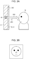
- Fig. 3A illustrates a positional relationship among the display screen 30D of the display unit 30, the camera element 40, and a user 1 in the case of the video phone of the mobile phone terminal 20 according to the present embodiment.
- Fig. 3B illustrates the captured image of a user 1 using the camera element 40 based on this positional relationship.
- a user performs communication using the video phone by activating the video phone function while looking at the display screen 30D from the direction of the arrow AR3.
- the image of a user captured using the camera element 40 is sent to the counterpart.
- the gaze direction of a user 1 is directed along the arrow AR3 to face the camera element 40 on the back surface of the display screen 30D.
- the gaze direction of a user 1 is on the same line as the camera shot direction of the camera element 40 indicated by the arrow AR4 of Fig. 3A , but their directions are opposite to each other. Therefore, the image captured by the camera element 40 becomes the front image in which the gaze direction is directed to the counterpart as shown in Fig. 3B .
- the camera element 40 is provided in the area of the display screen 30D of the display unit 30, it is unnecessary to the an area of the camera element in an area separate from the display screen 30D, and there is an effect that it is possible to increase the size of the display screen 30D that much.
- the camera element 40 receives the incident light through the display unit 30, in the case where the incident light of the camera element 40 is influenced by the existence of the display unit 30, it is necessary to remove such an influence.
- the transparent organic EL panel used as the transparent display device 31 according to the present embodiment.
- the electrode located in the back surface of the transparent display device 31 is made of, for example, a metal such as aluminum, and the luminescent light from the hole-injection layer/organic electroluminescent layer (EL layer) is output only to the surface side.
- both two-layered electrodes interposing the hole-injection layer/organic electroluminescent layer (EL layer) include a transparent electrode made of, for example, indium tin oxide (ITO).
- ITO indium tin oxide
- the single-sided emission type transparent organic EL panel is used as the transparent display device 31, it is regarded that there is almost no incidence of the luminescent light from the corresponding transparent organic EL panel to the camera element 40 provided in the back surface side. Therefore, since the camera element 40 is not influenced by the display image of the transparent display device 31 of the display unit 30, it is optimal to use the single-sided emission type transparent organic EL panel as the transparent display device 31. However, in the case where the single-sided emission type transparent organic EL panel is used as the transparent display device 31, the light quantity transmitting to the back surface side of the transparent display device 31, that is, the light quantity incident to the camera element 40 is reduced.
- the dual-sided emission type transparent organic EL panel is used, reduction of the light quantity transmitting to the back surface side of the transparent display device 31 is negligible.
- the luminescent light from the hole-injection layer/organic electroluminescent layer (EL layer) is also incident to the camera element 40 provided in the back surface side. For this reason, the incident light of the camera element 40 is influenced by the color image displayed on the display unit 30.
- the dual-sided emission type transparent organic EL panel is used as the transparent display device 31.
- correction for removing the influence of the color image displayed on the display unit 30 is performed for the output capturing image data of the camera element 40.
- Fig. 4 is a block diagram illustrating an exemplary structure of the hard disc of the internal electronic circuit of the mobile phone terminal 20 according to the present embodiment.
- a host control unit 111 including a microcomputer, the main memory 112, and the buffer memory 113 are connected to the system bus including the control bus 101 and the data bus 102.
- the communication circuit 114, the display controller 115, the manipulation unit 116, the camera control unit 117, and the camera color correction control unit 118 are connected to the system bus.
- the microcomputer of the host control unit 111 stores a software program for controlling various processes of the mobile phone terminal according to the present embodiment.
- the host control unit 111 executes various control processes based on such a software program.
- the main memory 112 stores, for example, data such as phone book data or mail addresses of the mobile phone terminal 20, or a uniform resource locator (URL) of the counterpart who accesses through the Internet.
- the main memory 112 may store the image data captured using the camera element 40.
- the main memory 112 stores accumulation data (including an application program) created by the functions provided in the mobile phone terminal 20.
- the buffer memory 113 is used as a work area when the host control unit 111 executes the processes based on the software program.
- the telephone communication circuit 114 is a radio communication unit for the mobile phone communication to execute telephone communication or other information communication (including communication via the Internet) via a base station and a mobile phone network and receives/transmits communication data through the antenna 114AT.
- a speaker 22 functioning as a receiver and a microphone 23 functioning as a transmitter are connected to the data bus 102.
- the call voice from the counterpart, received by the telephone communication circuit 114 is emitted from the speaker 22, and the transmitted voice received by the microphone 23 is transmitted to the counterpart through the telephone communication circuit 114.
- the telephone communication circuit 114 also transmits/receives the image data of the image captured by the camera element 40 in the case of the video phone.
- the transparent display device 31 is connected to the display controller 115.
- the transparent display device 31 displays various images under control of the host control unit 111 and simultaneously displays the image of the counterpart transmitted from the counterpart in the case of the video phone.
- the manipulation unit 116 includes a numeric key pad, an up-down-left-right key set for selecting menu, and other keys.
- the host control unit 111 is configured to detect what kind of key is pressed using the manipulation unit 116 and execute the control process operation corresponding to the manipulated key.
- the camera element 40 is connected to the camera control unit 117.
- the captured image data from the camera element 40 are received by the data bus 102 through the camera control unit 118.
- the camera color correction control unit 118 receives the captured image data read by the camera control unit 118 from the camera element 40 via the data bus 102 and performs color correction under control of the host control unit 111.
- the camera color correction control unit 118 may be configured to execute the control process under control of the host control unit 111 as a configuration including the microcomputer.
- the camera color correction control unit 118 may be configured as a software function executed by the host control unit 111 based on the software program.
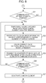
- Figs. 5 and 6 are flowcharts illustrating an exemplary flow of the color correction process for the captured image data from the camera element 40.
- the processes of each step of the flowcharts of Figs. 5 and 6 are executed by the host control unit 111 and the camera color correction control unit 118.
- the host control unit 111 monitors the manipulation input from the manipulation unit 116 and determines whether or not the manipulation for activating the camera element 40 is made (step S1).
- the manipulation for activating the camera element 40 includes manipulation for operating the video phone and the camera shot using the corresponding camera element 40.
- the camera shot may include a still image shot mode and a moving picture shot mode, descriptions thereof are simple, and thus, the following description is based on only the still image shot mode.
- step S1 if it is determined that the manipulation for activating the camera element 40 is not made, the process routine of the host control unit 111 advances to other processes (step S2). Then, after completing the process of the step S2, the process routine of the host control unit 111 is returned to the step S1, and the processes after the step S1 are repeated.
- the host control unit 111 controls the camera control unit 117 to activate the camera element 40 (step S3).
- the host control unit 111 determines whether or not the manipulation for activating the camera element 40 is the activation manipulation of the video phone mode (step S4). In the step S4, if it is determined that it is not the activation manipulation of the video phone mode, the host control unit 111 determines that manipulation for activating the camera element 40 is the camera shot mode, and it is determined whether or not a shutter manipulation is made using the manipulation unit 116 (step S5).
- step S5 if it is determined that the shutter manipulation is made, the host control unit 111 controls the camera control unit 117 to temporarily store the captured image data from the camera element 40 in the buffer memory 113 (step S6).
- the host control unit 111 transmits the color image information portion for creating the color image displayed on the display area corresponding to the camera element 40 out of the entire display area of the display screen 30D to the camera color correction control unit 118, where the color image information portion is referenced (step S7).
- the display area corresponding to the referenced color image information portion is selected considering the incident light from the inclined direction as well as the incident light from the direction along the optical axis of the lens of the camera element 40. For this reason, the display area corresponding to the referenced color image information portion is centered at the corresponding position directly over the center of the lens of the camera element 40 and has a larger area than the size of the lens considering the light incidence from the inclined direction.
- host control unit 111 controls the camera color correction control unit 118 to execute color correction based on the referenced color image information portion for the captured image data stored in the buffer memory 113 (step S8).
- the camera color correction control unit 118 performs color correction for the captured image data stored in the buffer memory 113 to remove the color caused by the luminescent light from the reference color image information portion of the transparent display device 31.
- the camera color correction control unit 118 is adapted to store the captured image data after the color correction in the main memory 12 (step S8). As a result, the color image data of the still image at the time point when the shutter is manipulated are stored in the main memory 12. After the step S8, the process returns to the step S1, and the processes subsequent to the step S1 are repeated.
- step S5 if it is determined that the shutter is not manipulated, the host control unit 111 determines whether or not manipulation of terminating the camera shot mode has been made (step S10). Then, in step S10, if it is determined that the manipulation of termination has not been made, the host control unit 111 returns the process to the step S5 and repeats the processes subsequent to the step S5.
- step S10 if it is determined that the manipulation of terminating the camera shot mode has been made, the host control unit 111 controls the camera control unit 117 to stop the operation of the camera element 40 (step S11). Then, the host control unit 111 returns the process to the step S1 and repeats the processes subsequent to the step S1.
- step S4 if it is determined that the manipulation of activating the video phone mode has been made, the host control unit 111 waits until the video phone has a communication state (step S21 in Fig. 6 ). In step S21, if it is determined that the video phone has a communication state, the host control unit 111 controls the camera control unit 117 to temporarily store the captured image data from the camera element 40 in the buffer memory 113 (step S22).
- the host control unit 111 transmits the color image information portion used to create the color image displayed in the display area corresponding to the camera element 40 out of the entire display area of the display screen 30D to the camera color correction control unit 118, where the color image information portion is referenced (step S23). Similar to the step S8, the host control unit 111 controls the camera color correction control unit 118 to perform color correction based on the referenced color image information portion for the captured image data stored in the buffer memory 113 (step S24).
- the camera color correction control unit 118 transmits the captured image data subjected to the color correction to the telephone communication circuit 114.
- the telephone communication circuit 114 converts the received captured image data into transmission data along with the voice data received through the microphone 23 and transmits the data to the counterpart (step S25).
- the host control unit 111 determines whether or not the manipulation of terminating video phone communication has been made (step S26). If it is determined that the manipulation of terminating communication has not been made, the process returns to the step S22, and the processes subsequent to the step S22 are repeated.
- step S26 if it is determined that the manipulation of terminating video phone communication has been made, the host control unit 111 controls the camera control unit 117 to stop the operation of the camera element 40 (step S27). Then, the host control unit 111 returns the process to the step S1 and repeats the processes subsequent to the step S1.
- the camera element 40 is provided on the back surface of the transparent display device 31. For this reason, if the color image is displayed in the corresponding transparent display device 31, the color pickup image from the camera element 40 may be colored by such a captured color image.
- color correction is applied to the captured color image from the camera element 40 based on the display image of the transparent display device 31. Therefore, it is possible to reduce or remove coloring of the captured image.
- the display image of the transparent display device 31 is a color image in the aforementioned description, coloring correction based on the corresponding color display image is performed for the captured image data from the camera element 40.
- the correction of the captured image data from the camera element 40 may be performed based on the display image data.
- the captured image data obtained from the camera element 40 have light and shade depending on the display image.
- the luminance correction may be performed for the captured image data from the camera element 40 based on the monochrome display image data thereof. That is, a configuration for correcting the gain of the captured image data from the camera element 40 based on the light transmission amount at the display screen position corresponding to the light incident position to the camera element 40 may be provided.
- the disclosure is not limited to the configuration in which the print layer is provided on the back surface of the transparent display device 31 as a way for visually obscuring the camera element 40 by way of an example of a sensor on the back surface of the transparent display device 31.
- the same print layer may be provided on the surface of the substrate 50 where the camera element 40 is provided (the surface facing the back surface of the transparent display device 31) without providing the print layer 34 on the back surface of the transparent display device 31.
- a sheet having the same optical reflection properties as that of the print layer 34 may be arranged on the back surface of the display screen of the transparent display device 31.
- the entire surface of the substrate 50 (including the camera element 40) where the camera element 40 is provided may be covered by a color shade film having an optical transmittance of, for example, 40% to 60%.
- the substrate 50 is not necessarily provided on the back surface of the display screen 30D of the display unit 30, but the camera element 40 or the display unit 30 may be electrically connected to the substrate provided in a portion other than the back surface of the display screen 30D of the display unit 30 through a lead portion including a flexible substrate.
- the same print layer as the print layer 34 may be provided on the internal wall surface of the casing 21 without providing the print layer 34 on the back surface of the transparent display device 31.
- the number of the camera elements provided on the back surface of the transparent display device 31 may be plural in the present disclosure.
- double camera elements for left and right eyes may be provided to obtain a 3D image as the captured image.
- the manipulation unit is configured to provide a manipulation button group in a separate area from the display screen 30D in the aforementioned embodiment
- the manipulation unit may be configured by providing a transparent touch panel on the surface of the display screen 30D and arranging button icons on the display screen 30D.
- the aforementioned camera color correction control unit 118 may be omitted.
- the decay amount of the incident light in the single-sided emission type transparent organic EL panel it would be preferable to perform correction to increase the incident light sensitivity of the camera element 40 or the gain of the captured image data from the camera element.
- the aforementioned embodiment relates to a mobile phone terminal.
- the display screen 30D is made to usually display any sort of image while the power supply is applied. Therefore, as described above, when the image is captured using the camera element 40, it is necessary to correct the captured image data output therefrom based on the display image. However, it is needless to say that, in the case of an electronic apparatus capable of turning on or off image display on the display unit 30, the display unit 30 has a transparent state by turning off image display on the display unit 30 when the camera element 40 is operated, so that the aforementioned correction becomes unnecessary.
- the camera element is exemplarily arranged as a sensor on the back surface of the display screen.
- an illuminance sensor and a proximity sensor are provided as the sensor.
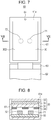
- Fig. 7 is a diagram for describing an exemplary appearance of an electronic apparatus according to the second embodiment, in which a foldable mobile phone terminal 60 is exemplified.
- the upper casing 61 and the lower casing 62 are openably assembled about the rotation hinge 63 of the rotation hinge portion 63.
- the foldable mobile phone terminal 60 is opened at a predetermined angle, and the internal face 61a of the upper casing 61 is shown from a perpendicular direction therefrom.
- Fig. 7 corresponds to Fig. 14B which shows a foldable mobile phone terminal of the related art.
- Fig. 8 is a cross-sectional view taken along the line VIII-VIII for illustrating the mobile phone terminal 60 of Fig. 7 .
- the internal face 61a of the upper casing 61 includes a display unit having the same structure as that of the display unit 30 of the first embodiment. Since the display unit of the mobile phone terminal 60 of the second embodiment is similar to the display unit 30 of the first embodiment, like reference numerals denote like elements for convenience of description.
- the display unit 30 is provided on the internal face 61a of the upper casing 61.
- the illuminance sensor 71 and the proximity sensor 72 are provided for correcting the luminance of the display screen 30D on the back surface of the display screen 30D of the display unit 30.
- the speaker 64 for emitting a received voice during a call is provided near the upper end in the area separate from the display screen 30D of the internal face 61a of the upper casing 61.
- the print layer 34 is provided to visually obscure two sensors 71 and 72 provided on the back surface of the transparent display device 31 as shown in Fig. 8 .
- the print layer 34 is provided on the back surface of the transparent display device 31 except for the portions opposite to the surfaces of the sensors 71 and 72. This print layer 34 visually obscures the two sensors 71 and 72 provided on the back surface of the transparent display device 31.
- the print layer 34 is formed to have the same optical reflection properties as those of the surfaces of the two sensors 71 and 72 facing the back surface of the transparent display device 31. For example, when the surfaces of the sensors 71 and 72 facing the back surface of the transparent display device 31 look black, the print layer 34 has a black color. In addition, when the surfaces of the sensors 71 and 72 facing the back surface of the transparent display device 31 have gloss, the print layer may have the same gloss. In addition, any material can be employed as a material of the print layer 34 if it has the same optical reflection properties as those of the sensors 71 and 72 facing the back surface of the transparent display device 31.
- the mobile phone terminal 60 has the same internal circuit hardware configuration as that of the mobile phone terminal 20 of the first embodiment shown in Fig. 4 , and the sensors 71 and 72 are connected to the system bus through the interface thereof instead of the camera element 40.
- the host control unit of the mobile phone terminal 60 adjusts the luminance of the display screen 30D in response to the illuminance detected by the illuminance sensor 71 so as to make a user see it easily. For example, when the illuminance detected by the illuminance sensor 71 is low, and the environment used by the display screen 30D is relatively dark, the luminance of the display screen 30D is made to be relatively dark. In addition, when the illuminance detected by the illuminance sensor 71 is high, and the environment used by the display screen 30D is bright, the luminance of the display screen 30D is made to be bright.
- the illuminance sensor 71 is provided in the area overlapping with the display area of the corresponding display screen 30D on the back surface of the display screen 30D, it is possible to avoid the problems of the related art described above.
- a relationship among the sun 2, the display screen 30D, the illuminance sensor 71, and the user 1 when the mobile phone terminal 60 is used in an outdoor environment is illustrated in Fig. 9 .
- the display screen 30D is shaded by the shadow of the user 1.
- the illuminance sensor 71 is also shaded by the shadow of the user 1. Therefore, the illuminance detected by the illuminance sensor 71 is equal to that of the display screen 30D, and the luminance of the display screen 30D becomes optimal for the user 1 by adjusting the luminance of the display screen 30D based on the illuminance detected by the illuminance sensor 71.
- the proximity sensor 72 is configured of an infrared ray type proximity sensor and detects the approach of a user's face to the display screen 30D during a call and the approach of the lower casing 62 to the display screen 30D when the mobile phone terminal 60 is folded.
- the proximity sensor 72 includes an infrared ray luminescent element and an optical detector so that the infrared rays emitted from the infrared ray luminescent element, and reflected by and returned from the detection target are received by the optical detector.
- the electric power corresponding to the distance between the proximity sensor 72 and the detection target is output from the optical detector.
- the host control unit of the mobile phone terminal 60 determines that the detection target approaches within a certain distance when the output electric power from the optical detector of the proximity sensor 72 is equal to or larger than a predetermined value.
- the host control unit of the mobile phone terminal 60 controls the display unit 30 to be turned off when it is determined that the detection target approaches within a certain distance based on the output from the proximity sensor 72.
- the touch panel is also controlled to be turned off.
- the host control unit of the mobile phone terminal 60 turns off the display unit 30 to stop display on the display screen 30D when it is detected that the mobile phone terminal 60 is closed in a folded state based on the output from the proximity sensor 72.
- the host control unit turns on the display unit 30 to start display on the display screen 30D.
- the host control unit of the mobile phone terminal 60 turns off the display unit 30 when it is detected that a user's face approaches the display unit 30 to try making a call based on the output from the proximity sensor 72 to stop display on the display screen 30D.
- the host control unit of the mobile phone terminal 60 detects it based on the output of the proximity sensor 72, and turns on the display unit 30 to restart display on the display screen 30D.
- the proximity sensor 72 is also provided in the area separate from the display screen 30D on the same surface as that of the display screen 30D in the related art, the proximity sensor 72 may be provided on the back surface of the display screen 30D along with the illuminance sensor 71 according to the second embodiment. Therefore, it is possible to save the space for those sensors 71 and 72, and it is possible to accordingly increase the size of the display screen 30D.
- the modified example of the first embodiment described above may be applied to the second embodiment as a way of visually obscuring the sensors 71 and 72 provided on the back surface of the transparent display device 31.
- other modified examples described in the first embodiment may be similarly applied to the second embodiment.
- the illuminance sensor 71 and the proximity sensor 72 are provided on the back surface of the display screen 30D in the second embodiment described above, the camera element 40 described in the first embodiment may be additionally provided on the back surface of the display screen 30D.
- any other types may be used as the proximity sensor 72 without limitation to the infrared ray type.
- the second embodiment is not limited to the foldable mobile phone terminal, but may be applied to a so-called straight type mobile phone terminal.
- the third embodiment describes an example that a predetermined input manipulation is reliably detected using a sensor by displaying a guide indication for a predetermined input manipulation from a user on the display screen using the sensor provided on the back surface of the display screen, for example, in the case where the sensor detects a predetermined input manipulation from a user.
- a user's fingerprint is read by a fingerprint sensor, and fingerprint authentication of the corresponding user is executed, if an appropriate guide is not provided, a user who is not familiar with that may not know how to input the fingerprint.
- the example of the third embodiment is made to allow even a user who is not familiar with the fingerprint authentication to readily execute an input manipulation for the fingerprint authentication in the mobile phone terminal capable of executing the fingerprint authentication.
- Fig. 10 illustrates appearance of the mobile phone terminal 80 as an example of the electronic apparatus according to the third embodiment.
- Fig. 11 is a cross-sectional view taken along the line XI-XI of Fig. 10 .
- the mobile phone terminal 80 of the example shown in Fig. 10 is a so-called straight type mobile phone terminal and includes a casing 81 having a thin rectangular shape.
- the mobile phone terminal 80 of this example includes the display screen 30D of the display unit 30 corresponding to an embodiment of the sensor-equipped display apparatus of the present disclosure on one plane 81a of the casing 81.
- like reference numerals denote like elements for convenience of description.
- the display unit 30 is provided on one plane 81a of the casing 81.
- a fingerprint sensor 90 having a bar shape traversing across the display screen 30D is provided on the back surface of the display screen 30D of the display unit 30.
- the print layer 34 similar to that of the first embodiment described above is provided as a way for visually obscuring the fingerprint sensor 90 provided on the back surface of the transparent display device 31.
- a speaker 82 for emitting the received voice during a call is provided in the proximity of the upper end of the area separate from the display screen 30D of one plane 81a of the casing 81, and a microphone 83 for receiving transmitted voice during a call is provided in the proximity of the lower end.
- the mobile phone terminal 80 has a fingerprint authentication function and includes a manipulation button for activating the corresponding fingerprint authentication function.
- the mobile phone terminal 80 has the same internal circuit hardware configuration as that of the mobile phone terminal 20 of the first embodiment shown in Fig. 4 , and the fingerprint sensor 90 is connected to the system bus through the interface thereof instead of the camera element 40.
- the host control unit of the mobile phone terminal 80 detects that the fingerprint authentication function is activated by the manipulation input, the standby screen displayed on the display screen 30D until that time is converted into the fingerprint authentication screen.
- the fingerprint authentication screen On the fingerprint authentication screen, a guide indication regarding how a user is to make the fingerprint sensor 90 read the fingerprint is displayed.
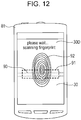
- An example of the fingerprint authentication screen is shown in Fig. 12 .
- a first guide image 91 for notifying a user of the approximate position of the fingerprint sensor 90 and a second guide image 92 for notifying a user of the fingerprint input position are displayed. Accordingly, a user may perform the fingerprint input manipulation based on the first and second guide images 91 and 92 displayed on the display screen 30D during the fingerprint authentication. As a result, the fingerprint sensor 90 can rapidly and reliably receive the fingerprint input, and it is possible to rapidly execute the fingerprint authentication.
- the host control unit of the mobile phone terminal 80 determines whether or not a manipulation of activating the fingerprint authentication function has been made (step S31). If it is determined that the activating manipulation has not been made, the standby screen is continuously displayed on the transparent display device 31 of the display unit 30, and other processes are executed (step S32).
- the host control unit displays the fingerprint authentication screen on the transparent display device 31 of the display unit 30 to switch from the standby screen that has been displayed until that time (step S33).
- the host control unit determines whether or not the fingerprint authentication manipulation and processing have been terminated from a user (step S34). If it is determined that the fingerprint authentication manipulation and processing have been terminated, the display screen of the transparent display device 31 of the display unit 30 is switched from the fingerprint authentication screen to the standby screen (step S35). In addition, the host control unit returns the process to step S31 and repeats the processes subsequent to the step S31.
- the fingerprint sensor 90 is provided on the back side of the display unit 30 including the transparent display device 31, and at the same time, a guide image for the fingerprint input manipulation may be displayed on the transparent display device 31. Therefore, a user can readily adjust the position of a finger based on the guide image when the fingerprint is input so that the fingerprint authentication can be readily made.
- first and second guide images 91 and 92 are still images in the aforementioned example
- a user may be notified of the speed of moving the user's finger when the fingerprint is input by exchanging the second guide image with a moving picture matching the motion of when a fingerprint is input.
- a voice may be emitted from the speaker 82 according to the voice guide message.
- a transparent touch panel may be provided on the display screen 30D, and an interface for indicating and manipulating the icon button displayed on the display screen 30D may be provided by the corresponding touch panel.
- the mobile phone terminal is exemplified as the electronic apparatus in the aforementioned embodiment, it is needless to say that the electronic apparatus of the present disclosure is not limited to the mobile phone terminal.
- the present disclosure may be applied to any electronic apparatus if the display screen and the sensor are provided on one surface of the casing.
- the transparent organic EL panel is used as the transparent display device in the aforementioned embodiment, the present disclosure is not limited thereto.
- a transparent liquid crystal display (LCD) panel may be used as the transparent display device.
Landscapes
- Engineering & Computer Science (AREA)
- Signal Processing (AREA)
- Multimedia (AREA)
- Telephone Set Structure (AREA)
- Telephone Function (AREA)
- Controls And Circuits For Display Device (AREA)
- Devices For Indicating Variable Information By Combining Individual Elements (AREA)
- Control Of Indicators Other Than Cathode Ray Tubes (AREA)
- Position Input By Displaying (AREA)
Priority Applications (2)
| Application Number | Priority Date | Filing Date | Title |
|---|---|---|---|
| EP25201976.5A EP4672734A3 (de) | 2010-09-21 | 2011-07-04 | Mit sensor ausgestattete anzeigevorrichtung und elektronische vorrichtung |
| EP22172960.1A EP4084448B1 (de) | 2010-09-21 | 2011-07-04 | Mit sensor ausgestattete anzeigevorrichtung |
Applications Claiming Priority (4)
| Application Number | Priority Date | Filing Date | Title |
|---|---|---|---|
| US3849641P | 2010-09-21 | 2010-09-21 | |
| US38496410P | 2010-09-21 | 2010-09-21 | |
| EP11172545.3A EP2432196B1 (de) | 2010-09-21 | 2011-07-04 | Mit Sensor ausgestattete Anzeigevorrichtung und elektronische Vorrichtung |
| EP17207401.5A EP3334131B1 (de) | 2010-09-21 | 2011-07-04 | Mit sensor ausgestattete anzeigevorrichtung und elektronische vorrichtung |
Related Parent Applications (3)
| Application Number | Title | Priority Date | Filing Date |
|---|---|---|---|
| EP17207401.5A Division EP3334131B1 (de) | 2010-09-21 | 2011-07-04 | Mit sensor ausgestattete anzeigevorrichtung und elektronische vorrichtung |
| EP17207401.5A Division-Into EP3334131B1 (de) | 2010-09-21 | 2011-07-04 | Mit sensor ausgestattete anzeigevorrichtung und elektronische vorrichtung |
| EP11172545.3A Division EP2432196B1 (de) | 2010-09-21 | 2011-07-04 | Mit Sensor ausgestattete Anzeigevorrichtung und elektronische Vorrichtung |
Related Child Applications (3)
| Application Number | Title | Priority Date | Filing Date |
|---|---|---|---|
| EP22172960.1A Division-Into EP4084448B1 (de) | 2010-09-21 | 2011-07-04 | Mit sensor ausgestattete anzeigevorrichtung |
| EP22172960.1A Division EP4084448B1 (de) | 2010-09-21 | 2011-07-04 | Mit sensor ausgestattete anzeigevorrichtung |
| EP25201976.5A Division EP4672734A3 (de) | 2010-09-21 | 2011-07-04 | Mit sensor ausgestattete anzeigevorrichtung und elektronische vorrichtung |
Publications (2)
| Publication Number | Publication Date |
|---|---|
| EP3703347A1 true EP3703347A1 (de) | 2020-09-02 |
| EP3703347B1 EP3703347B1 (de) | 2022-06-15 |
Family
ID=44533830
Family Applications (5)
| Application Number | Title | Priority Date | Filing Date |
|---|---|---|---|
| EP20155934.1A Active EP3703347B1 (de) | 2010-09-21 | 2011-07-04 | Mit sensor ausgestattete anzeigevorrichtung und elektronische vorrichtung |
| EP17207401.5A Active EP3334131B1 (de) | 2010-09-21 | 2011-07-04 | Mit sensor ausgestattete anzeigevorrichtung und elektronische vorrichtung |
| EP22172960.1A Active EP4084448B1 (de) | 2010-09-21 | 2011-07-04 | Mit sensor ausgestattete anzeigevorrichtung |
| EP25201976.5A Pending EP4672734A3 (de) | 2010-09-21 | 2011-07-04 | Mit sensor ausgestattete anzeigevorrichtung und elektronische vorrichtung |
| EP11172545.3A Active EP2432196B1 (de) | 2010-09-21 | 2011-07-04 | Mit Sensor ausgestattete Anzeigevorrichtung und elektronische Vorrichtung |
Family Applications After (4)
| Application Number | Title | Priority Date | Filing Date |
|---|---|---|---|
| EP17207401.5A Active EP3334131B1 (de) | 2010-09-21 | 2011-07-04 | Mit sensor ausgestattete anzeigevorrichtung und elektronische vorrichtung |
| EP22172960.1A Active EP4084448B1 (de) | 2010-09-21 | 2011-07-04 | Mit sensor ausgestattete anzeigevorrichtung |
| EP25201976.5A Pending EP4672734A3 (de) | 2010-09-21 | 2011-07-04 | Mit sensor ausgestattete anzeigevorrichtung und elektronische vorrichtung |
| EP11172545.3A Active EP2432196B1 (de) | 2010-09-21 | 2011-07-04 | Mit Sensor ausgestattete Anzeigevorrichtung und elektronische Vorrichtung |
Country Status (4)
| Country | Link |
|---|---|
| US (1) | US9013613B2 (de) |
| EP (5) | EP3703347B1 (de) |
| JP (1) | JP2012070356A (de) |
| CN (1) | CN102411878B (de) |
Cited By (1)
| Publication number | Priority date | Publication date | Assignee | Title |
|---|---|---|---|---|
| US12541139B2 (en) | 2013-05-21 | 2026-02-03 | Semiconductor Energy Laboratory Co., Ltd. | Light-emitting device and camera |
Families Citing this family (101)
| Publication number | Priority date | Publication date | Assignee | Title |
|---|---|---|---|---|
| US8791792B2 (en) * | 2010-01-15 | 2014-07-29 | Idex Asa | Electronic imager using an impedance sensor grid array mounted on or about a switch and method of making |
| US8421890B2 (en) | 2010-01-15 | 2013-04-16 | Picofield Technologies, Inc. | Electronic imager using an impedance sensor grid array and method of making |
| US8866347B2 (en) | 2010-01-15 | 2014-10-21 | Idex Asa | Biometric image sensing |
| US8604906B1 (en) | 2010-11-18 | 2013-12-10 | Sprint Spectrum L.P. | Method and system for secret fingerprint scanning and reporting |
| KR101160681B1 (ko) | 2011-10-19 | 2012-06-28 | 배경덕 | 이동 통신 단말기의 활성화 시에 특정 동작이 수행되도록 하기 위한 방법, 이동 통신 단말기 및 컴퓨터 판독 가능 기록 매체 |
| CN102520852A (zh) * | 2011-11-29 | 2012-06-27 | 华为终端有限公司 | 一种移动设备屏幕状态的控制方法及相关移动设备 |
| TWI430012B (zh) * | 2011-12-05 | 2014-03-11 | Hannspree Inc | 影像擷取觸控顯示器 |
| EP2836960B1 (de) | 2012-04-10 | 2018-09-26 | Idex Asa | Biometrische erfassung |
| TWI457790B (zh) * | 2012-06-13 | 2014-10-21 | Pixart Imaging Inc | 可攜式電子裝置及使用於可攜式電子裝置的方法 |
| GB2507839B (en) * | 2012-06-20 | 2019-06-12 | Shenzhen Liantronics Co Ltd | LED display module, LED television, and LED television system |
| CN102740029A (zh) * | 2012-06-20 | 2012-10-17 | 深圳市联建光电股份有限公司 | Led显示模组、led电视及led电视系统 |
| FR2995419B1 (fr) | 2012-09-12 | 2015-12-11 | Commissariat Energie Atomique | Systeme d'interface utilisateur sans contact |
| DE102012108838A1 (de) * | 2012-09-19 | 2014-05-28 | Cross Match Technologies Gmbh | Verfahren und Vorrichtung zur Aufnahme von Fingerabdrücken auf Basis von Fingerabdruckscannern in zuverlässig hoher Qualität |
| WO2014054084A1 (ja) * | 2012-10-05 | 2014-04-10 | パイオニア株式会社 | 半導体デバイス、これを備えた近接センサーおよび半導体デバイスの製造方法 |
| CN106969830B (zh) * | 2012-10-15 | 2018-12-07 | 华为终端(东莞)有限公司 | 一种增加光传感器接收角度的方法、结构及手持终端 |
| FR2996933B1 (fr) | 2012-10-15 | 2016-01-01 | Isorg | Appareil portable a ecran d'affichage et dispositif d'interface utilisateur |
| TWI515414B (zh) * | 2012-12-06 | 2016-01-01 | 仁寶電腦工業股份有限公司 | 手持式電子裝置 |
| US9240162B2 (en) * | 2012-12-31 | 2016-01-19 | Lg Display Co., Ltd. | Transparent display apparatus and method for controlling the same |
| US9310843B2 (en) | 2013-01-02 | 2016-04-12 | Apple Inc. | Electronic devices with light sensors and displays |
| WO2015005959A1 (en) * | 2013-04-01 | 2015-01-15 | Patrick Baudisch | A touchscreen capable of fingerprint recognition |
| CN103338282A (zh) * | 2013-06-07 | 2013-10-02 | 广东欧珀移动通信有限公司 | 一种移动设备及其控制方法 |
| CN103513412B (zh) | 2013-09-16 | 2015-10-07 | 华为终端有限公司 | 潜望式镜头和终端设备 |
| KR102358935B1 (ko) | 2014-02-12 | 2022-02-04 | 가부시키가이샤 한도오따이 에네루기 켄큐쇼 | 전자 기기 |
| US10732771B2 (en) | 2014-11-12 | 2020-08-04 | Shenzhen GOODIX Technology Co., Ltd. | Fingerprint sensors having in-pixel optical sensors |
| WO2016075783A1 (ja) * | 2014-11-13 | 2016-05-19 | 福井誠司 | スマートフォンの通話中誤動作防止装置 |
| EP3089064A1 (de) * | 2015-04-08 | 2016-11-02 | LG Electronics Inc. | Tragbares endgerät und verfahren zur steuerung davon |
| US10437974B2 (en) | 2015-06-18 | 2019-10-08 | Shenzhen GOODIX Technology Co., Ltd. | Optical sensing performance of under-screen optical sensor module for on-screen fingerprint sensing |
| WO2017076292A1 (en) | 2015-11-02 | 2017-05-11 | Shenzhen Huiding Technology Co., Ltd. | Multifunction fingerprint sensor having optical sensing against fingerprint spoofing |
| EP3278272B1 (de) | 2015-06-18 | 2020-12-09 | Shenzhen Goodix Technology Co., Ltd. | Multifunktionsfingerabdrucksensor mit optischer abtastfähigkeit |
| US10410033B2 (en) | 2015-06-18 | 2019-09-10 | Shenzhen GOODIX Technology Co., Ltd. | Under-LCD screen optical sensor module for on-screen fingerprint sensing |
| CN107004130B (zh) * | 2015-06-18 | 2020-08-28 | 深圳市汇顶科技股份有限公司 | 用于屏幕上指纹感应的屏幕下光学传感器模块 |
| US10410037B2 (en) | 2015-06-18 | 2019-09-10 | Shenzhen GOODIX Technology Co., Ltd. | Under-screen optical sensor module for on-screen fingerprint sensing implementing imaging lens, extra illumination or optical collimator array |
| KR102546135B1 (ko) * | 2015-09-28 | 2023-06-20 | 애플 인크. | 연장된 활성 영역을 갖는 전자 디바이스 디스플레이 |
| US10381381B1 (en) | 2015-10-20 | 2019-08-13 | Apple Inc. | Display with light transmitting windows |
| US10644077B1 (en) | 2015-10-28 | 2020-05-05 | Apple Inc. | Display with array of light-transmitting windows |
| US9736383B2 (en) * | 2015-10-30 | 2017-08-15 | Essential Products, Inc. | Apparatus and method to maximize the display area of a mobile device |
| US9525764B1 (en) | 2015-10-30 | 2016-12-20 | Essential Products, Inc. | Co-mold features on a chassis shell of a mobile device |
| US9762781B2 (en) | 2015-10-30 | 2017-09-12 | Essential Products, Inc. | Apparatus and method to maximize the display area of a mobile device by increasing the size of the display without necessarily increasing the size of the phone |
| US10157590B1 (en) | 2015-12-15 | 2018-12-18 | Apple Inc. | Display with localized brightness adjustment capabilities |
| JP6700770B2 (ja) * | 2015-12-16 | 2020-05-27 | キヤノン株式会社 | 表示装置、その制御方法、および制御プログラム |
| KR102504308B1 (ko) * | 2016-03-02 | 2023-02-28 | 삼성전자주식회사 | 디스플레이의 밝기를 제어하는 방법, 전자 장치 및 컴퓨터 판독가능 기록매체 |
| CN106990876A (zh) * | 2016-03-08 | 2017-07-28 | 罗天成 | 一种没有附加触摸屏的新型自带触摸功能电子产品 |
| KR20170111827A (ko) * | 2016-03-29 | 2017-10-12 | 삼성전자주식회사 | 디스플레이 및 카메라를 포함하는 전자 장치 |
| WO2017183910A2 (en) * | 2016-04-19 | 2017-10-26 | Samsung Electronics Co., Ltd. | Electronic device supporting fingerprint verification and method for operating the same |
| KR101796660B1 (ko) | 2016-04-19 | 2017-11-10 | 삼성전자주식회사 | 지문 인식 기능을 지원하는 전자 장치 및 이의 운용 방법 |
| CN107656665A (zh) | 2016-07-25 | 2018-02-02 | 印象认知(北京)科技有限公司 | 基于显示屏的指纹采集控制方法、装置及电子设备 |
| KR102694995B1 (ko) * | 2016-08-30 | 2024-08-14 | 삼성전자주식회사 | 디스플레이와 센서를 포함하는 전자 장치 및 그 동작 방법 |
| US10163984B1 (en) | 2016-09-12 | 2018-12-25 | Apple Inc. | Display with embedded components and subpixel windows |
| US10741621B2 (en) * | 2016-11-25 | 2020-08-11 | Lg Display Co., Ltd. | Display device with a fingerprint sensor |
| KR102779026B1 (ko) * | 2017-01-26 | 2025-03-11 | 삼성전자주식회사 | 전자 장치에 있어서 광 검출 장치 및 방법 |
| US10587738B2 (en) | 2017-01-26 | 2020-03-10 | Guangdong Oppo Mobile Telecommunications Corp., Ltd. | Display module and electronic device |
| CN106843398B (zh) * | 2017-01-26 | 2020-08-07 | Oppo广东移动通信有限公司 | 电子装置 |
| CN106603772B (zh) * | 2017-01-26 | 2019-12-27 | Oppo广东移动通信有限公司 | 电子装置及图像获取方法 |
| US10614283B2 (en) | 2017-03-07 | 2020-04-07 | Shenzhen GOODIX Technology Co., Ltd. | Devices with peripheral task bar display zone and under-LCD screen optical sensor module for on-screen fingerprint sensing |
| CN107193327A (zh) * | 2017-04-24 | 2017-09-22 | 广东欧珀移动通信有限公司 | 显示屏以及终端 |
| EP3982618B1 (de) | 2017-04-25 | 2023-03-15 | Huawei Technologies Co., Ltd. | Elektronische vorrichtung mit lcd-anzeige |
| CN110825171B (zh) * | 2017-04-27 | 2023-06-20 | Oppo广东移动通信有限公司 | 显示屏、显示装置及移动终端 |
| CN107092311B (zh) * | 2017-04-27 | 2020-03-03 | Oppo广东移动通信有限公司 | 显示屏、显示装置及移动终端 |
| CN107241466B (zh) * | 2017-05-04 | 2020-01-31 | Oppo广东移动通信有限公司 | 显示装置及移动终端 |
| CN107229148B (zh) * | 2017-05-05 | 2021-03-09 | Oppo广东移动通信有限公司 | 显示屏、显示装置及移动终端 |
| KR102350395B1 (ko) * | 2017-05-15 | 2022-01-14 | 엘지디스플레이 주식회사 | 평판 표시 패널 및 그의 제조 방법 |
| KR102430318B1 (ko) * | 2017-06-21 | 2022-08-10 | 삼성디스플레이 주식회사 | 표시 장치 및 그의 동작 방법 |
| KR102462246B1 (ko) * | 2017-09-11 | 2022-11-02 | 엘지디스플레이 주식회사 | 표시장치와 이 표시장치를 포함한 모바일 정보 단말기 |
| US10681281B2 (en) * | 2017-12-28 | 2020-06-09 | Htc Corporation | Mobile device, and image processing method for mobile device |
| KR102470004B1 (ko) | 2018-01-23 | 2022-11-24 | 삼성전자주식회사 | 픽셀과 적어도 일부가 겹치도록 배치된 적외선 소자가 구비된 디스플레이 및 이를 포함하는 전자 장치 |
| CN108323207B (zh) * | 2018-02-06 | 2021-02-26 | 深圳市汇顶科技股份有限公司 | 屏下生物特征识别装置、生物特征识别组件和终端设备 |
| CN108494936B (zh) * | 2018-02-11 | 2021-01-08 | 维沃移动通信有限公司 | 一种光强度的检测方法、移动终端 |
| CN111886570A (zh) * | 2018-02-15 | 2020-11-03 | 索尼公司 | 信息处理装置、信息处理方法、和可穿戴设备 |
| US20210105434A1 (en) * | 2018-02-26 | 2021-04-08 | Ntt Docomo, Inc. | Display imaging device |
| CN108600419A (zh) * | 2018-03-09 | 2018-09-28 | 广东欧珀移动通信有限公司 | 电子装置及其制造方法 |
| CN108534891B (zh) * | 2018-03-09 | 2021-11-05 | Oppo广东移动通信有限公司 | 光传感器、电子装置及其制造方法 |
| CN111984155B (zh) * | 2018-03-09 | 2023-07-18 | Oppo广东移动通信有限公司 | 电子装置及其制造方法 |
| CN108600455B (zh) * | 2018-04-27 | 2020-12-15 | Oppo广东移动通信有限公司 | 电子设备 |
| CN115086519A (zh) * | 2018-05-08 | 2022-09-20 | Oppo广东移动通信有限公司 | 终端设备和图像获取方法 |
| WO2019213842A1 (en) | 2018-05-08 | 2019-11-14 | Guangdong Oppo Mobile Telecommunications Corp., Ltd. | Terminal device and dual front-facing camera operating method |
| CN108769304B (zh) * | 2018-05-16 | 2024-02-06 | Oppo广东移动通信有限公司 | 电子装置 |
| CN108650354B (zh) * | 2018-05-16 | 2020-08-28 | 维沃移动通信有限公司 | 一种显示模组及移动终端 |
| KR102036204B1 (ko) | 2018-06-18 | 2019-10-24 | 양경호 | 휴대형 이동통신 단말기의 자기 영상 촬영장치 및 그 제어 방법 |
| CN108803143A (zh) * | 2018-06-29 | 2018-11-13 | 厦门天马微电子有限公司 | 背光模组及显示装置 |
| JP2020020849A (ja) * | 2018-07-30 | 2020-02-06 | 株式会社ジャパンディスプレイ | 電子機器 |
| CN110808263B (zh) * | 2018-08-06 | 2020-09-22 | 云谷(固安)科技有限公司 | 显示面板、显示屏及显示终端 |
| WO2020061856A1 (en) | 2018-09-26 | 2020-04-02 | Guangdong Oppo Mobile Telecommunications Corp., Ltd. | Method and device for recovering image passing through display |
| CN114299827B (zh) | 2018-10-11 | 2023-11-17 | 京东方科技集团股份有限公司 | 一种显示面板及显示装置 |
| CN109637467B (zh) * | 2019-02-19 | 2020-10-30 | 昆山龙腾光电股份有限公司 | 一种显示面板及液晶显示装置 |
| CN109862159B (zh) * | 2019-03-08 | 2021-02-05 | 维沃移动通信有限公司 | 一种电子设备及电子设备控制方法 |
| JP2022078386A (ja) * | 2019-04-01 | 2022-05-25 | シャープ株式会社 | 表示装置、スマートフォン、及び表示方法 |
| CN110248004A (zh) * | 2019-06-25 | 2019-09-17 | Oppo广东移动通信有限公司 | 终端、终端的控制方法及图像获取方法 |
| CN110381189A (zh) * | 2019-08-12 | 2019-10-25 | Oppo广东移动通信有限公司 | 电池、摄像模组及电子设备 |
| US11153513B2 (en) * | 2019-08-19 | 2021-10-19 | Synaptics Incorporated | Light source for camera |
| CN112449084B (zh) * | 2019-08-28 | 2022-04-01 | Oppo广东移动通信有限公司 | 摄像头模组以及电子设备 |
| CN112449030B (zh) * | 2019-08-30 | 2023-05-30 | 北京小米移动软件有限公司 | 电子设备 |
| TWI853102B (zh) | 2019-10-07 | 2024-08-21 | 日商索尼半導體解決方案公司 | 電子機器 |
| CN111083374B (zh) * | 2019-12-27 | 2021-09-28 | 维沃移动通信有限公司 | 滤镜添加方法及电子设备 |
| CN111246116B (zh) * | 2020-03-20 | 2022-03-11 | 谌春亮 | 一种用于屏幕上智能取景显示的方法及移动终端 |
| US12256154B2 (en) | 2020-05-08 | 2025-03-18 | Sony Semiconductor Solutions Corporation | Electronic device and imaging device with image data correction |
| CN111599273B (zh) * | 2020-05-21 | 2022-06-03 | 北京小米移动软件有限公司 | 显示屏的控制方法、装置、终端设备及存储介质 |
| KR102717781B1 (ko) * | 2020-06-24 | 2024-10-16 | 삼성전자 주식회사 | 조도 센서를 포함하는 전자 장치 |
| CN117546201A (zh) * | 2021-06-30 | 2024-02-09 | 株式会社半导体能源研究所 | 电子设备 |
| US12482221B2 (en) | 2021-12-02 | 2025-11-25 | Samsung Electronics Co., Ltd. | Electronic device for obtaining illuminance data using image sensor |
| WO2023101156A1 (ko) * | 2021-12-02 | 2023-06-08 | 삼성전자 주식회사 | 이미지 센서를 이용하여 조도 데이터를 획득하기 위한 전자 장치 |
| CN114495776B (zh) * | 2021-12-28 | 2024-06-18 | 深圳市艾比森光电股份有限公司 | 采集显示屏发光数据的设备及方法 |
Citations (8)
| Publication number | Priority date | Publication date | Assignee | Title |
|---|---|---|---|---|
| JP2002296375A (ja) | 2001-03-29 | 2002-10-09 | Seiko Epson Corp | 情報表示装置、腕時計および携帯型情報機器 |
| US20040257473A1 (en) * | 2003-06-17 | 2004-12-23 | Keisuke Miyagawa | Display device having an image pickup function and a two-way communication system |
| US20040263069A1 (en) * | 2003-06-27 | 2004-12-30 | Shunpei Yamazaki | Display device and electronic device |
| US20070120879A1 (en) * | 2005-10-17 | 2007-05-31 | I2Ic Corporation | Combined Video Display and Camera System |
| JP2007201823A (ja) | 2006-01-26 | 2007-08-09 | Nikon Corp | 携帯電話 |
| WO2008047785A1 (en) * | 2006-10-17 | 2008-04-24 | Seiko Instruments Inc. | Display device |
| US20080158173A1 (en) * | 2007-01-03 | 2008-07-03 | Apple Computer, Inc. | Multi-touch surface stackup arrangement |
| US20080298571A1 (en) * | 2007-05-31 | 2008-12-04 | Kurtz Andrew F | Residential video communication system |
Family Cites Families (8)
| Publication number | Priority date | Publication date | Assignee | Title |
|---|---|---|---|---|
| JP3591699B2 (ja) * | 1997-10-09 | 2004-11-24 | 日東電工株式会社 | 偏光素子、光学素子、照明装置及び液晶表示装置 |
| US7420585B2 (en) * | 1999-11-30 | 2008-09-02 | Eastman Kodak Company | Image capture and display device |
| JP2006293013A (ja) * | 2005-04-11 | 2006-10-26 | Nippon Sheet Glass Co Ltd | 半透過型液晶表示素子用基板及び該基板を備える半透過型液晶表示素子 |
| US20080122821A1 (en) | 2006-11-24 | 2008-05-29 | Sony Ericsson Mobile Communications Ab | Luminance control for a display |
| JP4661875B2 (ja) | 2008-01-15 | 2011-03-30 | ソニー株式会社 | 表示装置及び表示装置の輝度調整方法 |
| KR101495164B1 (ko) | 2008-04-10 | 2015-02-24 | 엘지전자 주식회사 | 이동단말기 및 그 화면 처리 방법 |
| CN101650593B (zh) | 2008-08-12 | 2012-07-25 | Tcl集团股份有限公司 | 一种手持设备及用于该手持设备的输入方法 |
| US20100304787A1 (en) * | 2009-05-28 | 2010-12-02 | Min Ho Lee | Mobile terminal and method for displaying on a mobile terminal |
-
2011
- 2011-05-24 US US13/114,277 patent/US9013613B2/en active Active
- 2011-05-26 JP JP2011117534A patent/JP2012070356A/ja not_active Withdrawn
- 2011-07-04 EP EP20155934.1A patent/EP3703347B1/de active Active
- 2011-07-04 EP EP17207401.5A patent/EP3334131B1/de active Active
- 2011-07-04 EP EP22172960.1A patent/EP4084448B1/de active Active
- 2011-07-04 EP EP25201976.5A patent/EP4672734A3/de active Pending
- 2011-07-04 EP EP11172545.3A patent/EP2432196B1/de active Active
- 2011-07-26 CN CN201110209383.XA patent/CN102411878B/zh active Active
Patent Citations (9)
| Publication number | Priority date | Publication date | Assignee | Title |
|---|---|---|---|---|
| JP2002296375A (ja) | 2001-03-29 | 2002-10-09 | Seiko Epson Corp | 情報表示装置、腕時計および携帯型情報機器 |
| US20040257473A1 (en) * | 2003-06-17 | 2004-12-23 | Keisuke Miyagawa | Display device having an image pickup function and a two-way communication system |
| US20040263069A1 (en) * | 2003-06-27 | 2004-12-30 | Shunpei Yamazaki | Display device and electronic device |
| US20070120879A1 (en) * | 2005-10-17 | 2007-05-31 | I2Ic Corporation | Combined Video Display and Camera System |
| JP2007201823A (ja) | 2006-01-26 | 2007-08-09 | Nikon Corp | 携帯電話 |
| WO2008047785A1 (en) * | 2006-10-17 | 2008-04-24 | Seiko Instruments Inc. | Display device |
| US20100296027A1 (en) * | 2006-10-17 | 2010-11-25 | Tsutomu Matsuhira | Display device |
| US20080158173A1 (en) * | 2007-01-03 | 2008-07-03 | Apple Computer, Inc. | Multi-touch surface stackup arrangement |
| US20080298571A1 (en) * | 2007-05-31 | 2008-12-04 | Kurtz Andrew F | Residential video communication system |
Cited By (1)
| Publication number | Priority date | Publication date | Assignee | Title |
|---|---|---|---|---|
| US12541139B2 (en) | 2013-05-21 | 2026-02-03 | Semiconductor Energy Laboratory Co., Ltd. | Light-emitting device and camera |
Also Published As
| Publication number | Publication date |
|---|---|
| CN102411878A (zh) | 2012-04-11 |
| EP3703347B1 (de) | 2022-06-15 |
| EP2432196B1 (de) | 2018-01-24 |
| EP4084448B1 (de) | 2025-10-01 |
| EP4672734A3 (de) | 2026-01-21 |
| US9013613B2 (en) | 2015-04-21 |
| EP2432196A1 (de) | 2012-03-21 |
| JP2012070356A (ja) | 2012-04-05 |
| US20120069042A1 (en) | 2012-03-22 |
| EP3334131A1 (de) | 2018-06-13 |
| EP4672734A2 (de) | 2025-12-31 |
| EP4084448A1 (de) | 2022-11-02 |
| EP3334131B1 (de) | 2020-03-25 |
| CN102411878B (zh) | 2015-12-09 |
Similar Documents
| Publication | Publication Date | Title |
|---|---|---|
| EP3334131B1 (de) | Mit sensor ausgestattete anzeigevorrichtung und elektronische vorrichtung | |
| US11740716B2 (en) | Disposition structure of sensor of electronic device | |
| TWI541568B (zh) | 可攜式終端機 | |
| KR102695205B1 (ko) | 조도 센서를 이용하여 디스플레이의 밝기를 설정하는 폴더블 휴대 전자 장치 | |
| US11863855B2 (en) | Terminal device and image capturing method | |
| CN110581910A (zh) | 图像采集方法、装置、终端及存储介质 | |
| US11838615B2 (en) | Terminal device and dual front-facing camera operating method | |
| CN107621738B (zh) | 一种移动终端的控制方法及移动终端 | |
| CN107943211A (zh) | 终端设备及其控制方法 | |
| WO2018145555A1 (zh) | 显示屏状态控制方法、装置、存储介质及电子设备 | |
| US20050024500A1 (en) | Camera device, electronic device, and image processing method for same | |
| EP4089521A1 (de) | Verfahren und gerät zum betrieb einer elektronischen vorrichtung mit flexibler anzeige | |
| CN108833694B (zh) | 控制方法、控制装置、电子装置、计算机存储介质及设备 | |
| KR102806391B1 (ko) | 디스플레이를 포함하는 전자 장치 및 그 디스플레이의 시야각을 제어하는 방법 | |
| CN108803197A (zh) | 一种光学结构、成像装置、电子设备及光量调整方法 | |
| CN103294240A (zh) | 触控显示系统、显示装置及其画面关闭方法 | |
| CN110969949A (zh) | 复合型显示屏、复合型显示屏模块和其显示控制方法 | |
| US20220394193A1 (en) | Display device and method of driving the same | |
| KR20090093671A (ko) | 휴대 단말기 | |
| CN110248050A (zh) | 一种摄像头模组及移动终端 | |
| CN108696630B (zh) | 控制方法、控制装置、电子装置、计算机存储介质及设备 | |
| CN121008331A (zh) | 一种屏幕贴膜检测方法、终端、存储介质及程序产品 | |
| CN108989544A (zh) | 控制方法、控制装置、电子装置、计算机存储介质及设备 |
Legal Events
| Date | Code | Title | Description |
|---|---|---|---|
| PUAI | Public reference made under article 153(3) epc to a published international application that has entered the european phase |
Free format text: ORIGINAL CODE: 0009012 |
|
| STAA | Information on the status of an ep patent application or granted ep patent |
Free format text: STATUS: REQUEST FOR EXAMINATION WAS MADE |
|
| 17P | Request for examination filed |
Effective date: 20200221 |
|
| AC | Divisional application: reference to earlier application |
Ref document number: 2432196 Country of ref document: EP Kind code of ref document: P Ref document number: 3334131 Country of ref document: EP Kind code of ref document: P |
|
| AK | Designated contracting states |
Kind code of ref document: A1 Designated state(s): AL AT BE BG CH CY CZ DE DK EE ES FI FR GB GR HR HU IE IS IT LI LT LU LV MC MK MT NL NO PL PT RO RS SE SI SK SM TR |
|
| GRAP | Despatch of communication of intention to grant a patent |
Free format text: ORIGINAL CODE: EPIDOSNIGR1 |
|
| STAA | Information on the status of an ep patent application or granted ep patent |
Free format text: STATUS: GRANT OF PATENT IS INTENDED |
|
| RAP1 | Party data changed (applicant data changed or rights of an application transferred) |
Owner name: SONY GROUP CORPORATION |
|
| INTG | Intention to grant announced |
Effective date: 20220111 |
|
| GRAS | Grant fee paid |
Free format text: ORIGINAL CODE: EPIDOSNIGR3 |
|
| GRAA | (expected) grant |
Free format text: ORIGINAL CODE: 0009210 |
|
| STAA | Information on the status of an ep patent application or granted ep patent |
Free format text: STATUS: THE PATENT HAS BEEN GRANTED |
|
| AC | Divisional application: reference to earlier application |
Ref document number: 2432196 Country of ref document: EP Kind code of ref document: P Ref document number: 3334131 Country of ref document: EP Kind code of ref document: P |
|
| AK | Designated contracting states |
Kind code of ref document: B1 Designated state(s): AL AT BE BG CH CY CZ DE DK EE ES FI FR GB GR HR HU IE IS IT LI LT LU LV MC MK MT NL NO PL PT RO RS SE SI SK SM TR |
|
| REG | Reference to a national code |
Ref country code: CH Ref legal event code: EP Ref country code: GB Ref legal event code: FG4D |
|
| REG | Reference to a national code |
Ref country code: IE Ref legal event code: FG4D |
|
| REG | Reference to a national code |
Ref country code: DE Ref legal event code: R096 Ref document number: 602011073020 Country of ref document: DE |
|
| REG | Reference to a national code |
Ref country code: AT Ref legal event code: REF Ref document number: 1499087 Country of ref document: AT Kind code of ref document: T Effective date: 20220715 |
|
| REG | Reference to a national code |
Ref country code: LT Ref legal event code: MG9D |
|
| REG | Reference to a national code |
Ref country code: NL Ref legal event code: MP Effective date: 20220615 |
|
| PG25 | Lapsed in a contracting state [announced via postgrant information from national office to epo] |
Ref country code: SE Free format text: LAPSE BECAUSE OF FAILURE TO SUBMIT A TRANSLATION OF THE DESCRIPTION OR TO PAY THE FEE WITHIN THE PRESCRIBED TIME-LIMIT Effective date: 20220615 Ref country code: NO Free format text: LAPSE BECAUSE OF FAILURE TO SUBMIT A TRANSLATION OF THE DESCRIPTION OR TO PAY THE FEE WITHIN THE PRESCRIBED TIME-LIMIT Effective date: 20220915 Ref country code: LT Free format text: LAPSE BECAUSE OF FAILURE TO SUBMIT A TRANSLATION OF THE DESCRIPTION OR TO PAY THE FEE WITHIN THE PRESCRIBED TIME-LIMIT Effective date: 20220615 Ref country code: HR Free format text: LAPSE BECAUSE OF FAILURE TO SUBMIT A TRANSLATION OF THE DESCRIPTION OR TO PAY THE FEE WITHIN THE PRESCRIBED TIME-LIMIT Effective date: 20220615 Ref country code: GR Free format text: LAPSE BECAUSE OF FAILURE TO SUBMIT A TRANSLATION OF THE DESCRIPTION OR TO PAY THE FEE WITHIN THE PRESCRIBED TIME-LIMIT Effective date: 20220916 Ref country code: FI Free format text: LAPSE BECAUSE OF FAILURE TO SUBMIT A TRANSLATION OF THE DESCRIPTION OR TO PAY THE FEE WITHIN THE PRESCRIBED TIME-LIMIT Effective date: 20220615 Ref country code: BG Free format text: LAPSE BECAUSE OF FAILURE TO SUBMIT A TRANSLATION OF THE DESCRIPTION OR TO PAY THE FEE WITHIN THE PRESCRIBED TIME-LIMIT Effective date: 20220915 |
|
| REG | Reference to a national code |
Ref country code: AT Ref legal event code: MK05 Ref document number: 1499087 Country of ref document: AT Kind code of ref document: T Effective date: 20220615 |
|
| PG25 | Lapsed in a contracting state [announced via postgrant information from national office to epo] |
Ref country code: RS Free format text: LAPSE BECAUSE OF FAILURE TO SUBMIT A TRANSLATION OF THE DESCRIPTION OR TO PAY THE FEE WITHIN THE PRESCRIBED TIME-LIMIT Effective date: 20220615 Ref country code: LV Free format text: LAPSE BECAUSE OF FAILURE TO SUBMIT A TRANSLATION OF THE DESCRIPTION OR TO PAY THE FEE WITHIN THE PRESCRIBED TIME-LIMIT Effective date: 20220615 |
|
| PG25 | Lapsed in a contracting state [announced via postgrant information from national office to epo] |
Ref country code: NL Free format text: LAPSE BECAUSE OF FAILURE TO SUBMIT A TRANSLATION OF THE DESCRIPTION OR TO PAY THE FEE WITHIN THE PRESCRIBED TIME-LIMIT Effective date: 20220615 |
|
| PG25 | Lapsed in a contracting state [announced via postgrant information from national office to epo] |
Ref country code: SM Free format text: LAPSE BECAUSE OF FAILURE TO SUBMIT A TRANSLATION OF THE DESCRIPTION OR TO PAY THE FEE WITHIN THE PRESCRIBED TIME-LIMIT Effective date: 20220615 Ref country code: SK Free format text: LAPSE BECAUSE OF FAILURE TO SUBMIT A TRANSLATION OF THE DESCRIPTION OR TO PAY THE FEE WITHIN THE PRESCRIBED TIME-LIMIT Effective date: 20220615 Ref country code: RO Free format text: LAPSE BECAUSE OF FAILURE TO SUBMIT A TRANSLATION OF THE DESCRIPTION OR TO PAY THE FEE WITHIN THE PRESCRIBED TIME-LIMIT Effective date: 20220615 Ref country code: PT Free format text: LAPSE BECAUSE OF FAILURE TO SUBMIT A TRANSLATION OF THE DESCRIPTION OR TO PAY THE FEE WITHIN THE PRESCRIBED TIME-LIMIT Effective date: 20221017 Ref country code: ES Free format text: LAPSE BECAUSE OF FAILURE TO SUBMIT A TRANSLATION OF THE DESCRIPTION OR TO PAY THE FEE WITHIN THE PRESCRIBED TIME-LIMIT Effective date: 20220615 Ref country code: EE Free format text: LAPSE BECAUSE OF FAILURE TO SUBMIT A TRANSLATION OF THE DESCRIPTION OR TO PAY THE FEE WITHIN THE PRESCRIBED TIME-LIMIT Effective date: 20220615 Ref country code: CZ Free format text: LAPSE BECAUSE OF FAILURE TO SUBMIT A TRANSLATION OF THE DESCRIPTION OR TO PAY THE FEE WITHIN THE PRESCRIBED TIME-LIMIT Effective date: 20220615 Ref country code: AT Free format text: LAPSE BECAUSE OF FAILURE TO SUBMIT A TRANSLATION OF THE DESCRIPTION OR TO PAY THE FEE WITHIN THE PRESCRIBED TIME-LIMIT Effective date: 20220615 |
|
| PG25 | Lapsed in a contracting state [announced via postgrant information from national office to epo] |
Ref country code: PL Free format text: LAPSE BECAUSE OF FAILURE TO SUBMIT A TRANSLATION OF THE DESCRIPTION OR TO PAY THE FEE WITHIN THE PRESCRIBED TIME-LIMIT Effective date: 20220615 Ref country code: IS Free format text: LAPSE BECAUSE OF FAILURE TO SUBMIT A TRANSLATION OF THE DESCRIPTION OR TO PAY THE FEE WITHIN THE PRESCRIBED TIME-LIMIT Effective date: 20221015 |
|
| REG | Reference to a national code |
Ref country code: CH Ref legal event code: PL |
|
| REG | Reference to a national code |
Ref country code: DE Ref legal event code: R097 Ref document number: 602011073020 Country of ref document: DE |
|
| REG | Reference to a national code |
Ref country code: BE Ref legal event code: MM Effective date: 20220731 |
|
| PG25 | Lapsed in a contracting state [announced via postgrant information from national office to epo] |
Ref country code: MC Free format text: LAPSE BECAUSE OF FAILURE TO SUBMIT A TRANSLATION OF THE DESCRIPTION OR TO PAY THE FEE WITHIN THE PRESCRIBED TIME-LIMIT Effective date: 20220615 Ref country code: AL Free format text: LAPSE BECAUSE OF FAILURE TO SUBMIT A TRANSLATION OF THE DESCRIPTION OR TO PAY THE FEE WITHIN THE PRESCRIBED TIME-LIMIT Effective date: 20220615 |
|
| PLBE | No opposition filed within time limit |
Free format text: ORIGINAL CODE: 0009261 |
|
| STAA | Information on the status of an ep patent application or granted ep patent |
Free format text: STATUS: NO OPPOSITION FILED WITHIN TIME LIMIT |
|
| PG25 | Lapsed in a contracting state [announced via postgrant information from national office to epo] |
Ref country code: LU Free format text: LAPSE BECAUSE OF NON-PAYMENT OF DUE FEES Effective date: 20220704 Ref country code: LI Free format text: LAPSE BECAUSE OF NON-PAYMENT OF DUE FEES Effective date: 20220731 Ref country code: DK Free format text: LAPSE BECAUSE OF FAILURE TO SUBMIT A TRANSLATION OF THE DESCRIPTION OR TO PAY THE FEE WITHIN THE PRESCRIBED TIME-LIMIT Effective date: 20220615 Ref country code: CH Free format text: LAPSE BECAUSE OF NON-PAYMENT OF DUE FEES Effective date: 20220731 |
|
| 26N | No opposition filed |
Effective date: 20230316 |
|
| GBPC | Gb: european patent ceased through non-payment of renewal fee |
Effective date: 20220915 |
|
| PG25 | Lapsed in a contracting state [announced via postgrant information from national office to epo] |
Ref country code: SI Free format text: LAPSE BECAUSE OF FAILURE TO SUBMIT A TRANSLATION OF THE DESCRIPTION OR TO PAY THE FEE WITHIN THE PRESCRIBED TIME-LIMIT Effective date: 20220615 Ref country code: BE Free format text: LAPSE BECAUSE OF NON-PAYMENT OF DUE FEES Effective date: 20220731 |
|
| P01 | Opt-out of the competence of the unified patent court (upc) registered |
Effective date: 20230528 |
|
| PG25 | Lapsed in a contracting state [announced via postgrant information from national office to epo] |
Ref country code: IE Free format text: LAPSE BECAUSE OF NON-PAYMENT OF DUE FEES Effective date: 20220704 Ref country code: FR Free format text: LAPSE BECAUSE OF NON-PAYMENT OF DUE FEES Effective date: 20220815 |
|
| PG25 | Lapsed in a contracting state [announced via postgrant information from national office to epo] |
Ref country code: GB Free format text: LAPSE BECAUSE OF NON-PAYMENT OF DUE FEES Effective date: 20220915 |
|
| PG25 | Lapsed in a contracting state [announced via postgrant information from national office to epo] |
Ref country code: IT Free format text: LAPSE BECAUSE OF FAILURE TO SUBMIT A TRANSLATION OF THE DESCRIPTION OR TO PAY THE FEE WITHIN THE PRESCRIBED TIME-LIMIT Effective date: 20220615 |
|
| PG25 | Lapsed in a contracting state [announced via postgrant information from national office to epo] |
Ref country code: MK Free format text: LAPSE BECAUSE OF FAILURE TO SUBMIT A TRANSLATION OF THE DESCRIPTION OR TO PAY THE FEE WITHIN THE PRESCRIBED TIME-LIMIT Effective date: 20220615 Ref country code: CY Free format text: LAPSE BECAUSE OF FAILURE TO SUBMIT A TRANSLATION OF THE DESCRIPTION OR TO PAY THE FEE WITHIN THE PRESCRIBED TIME-LIMIT Effective date: 20220615 |
|
| PG25 | Lapsed in a contracting state [announced via postgrant information from national office to epo] |
Ref country code: HU Free format text: LAPSE BECAUSE OF FAILURE TO SUBMIT A TRANSLATION OF THE DESCRIPTION OR TO PAY THE FEE WITHIN THE PRESCRIBED TIME-LIMIT; INVALID AB INITIO Effective date: 20110704 |
|
| PG25 | Lapsed in a contracting state [announced via postgrant information from national office to epo] |
Ref country code: TR Free format text: LAPSE BECAUSE OF FAILURE TO SUBMIT A TRANSLATION OF THE DESCRIPTION OR TO PAY THE FEE WITHIN THE PRESCRIBED TIME-LIMIT Effective date: 20220615 |
|
| PG25 | Lapsed in a contracting state [announced via postgrant information from national office to epo] |
Ref country code: MT Free format text: LAPSE BECAUSE OF FAILURE TO SUBMIT A TRANSLATION OF THE DESCRIPTION OR TO PAY THE FEE WITHIN THE PRESCRIBED TIME-LIMIT Effective date: 20220615 |
|
| PG25 | Lapsed in a contracting state [announced via postgrant information from national office to epo] |
Ref country code: BG Free format text: LAPSE BECAUSE OF FAILURE TO SUBMIT A TRANSLATION OF THE DESCRIPTION OR TO PAY THE FEE WITHIN THE PRESCRIBED TIME-LIMIT Effective date: 20220615 |
|
| PG25 | Lapsed in a contracting state [announced via postgrant information from national office to epo] |
Ref country code: BG Free format text: LAPSE BECAUSE OF FAILURE TO SUBMIT A TRANSLATION OF THE DESCRIPTION OR TO PAY THE FEE WITHIN THE PRESCRIBED TIME-LIMIT Effective date: 20220615 |
|
| PGFP | Annual fee paid to national office [announced via postgrant information from national office to epo] |
Ref country code: DE Payment date: 20250620 Year of fee payment: 15 |