EP3699671A1 - Dispositif d'affichage tête haute - Google Patents
Dispositif d'affichage tête haute Download PDFInfo
- Publication number
- EP3699671A1 EP3699671A1 EP18869226.3A EP18869226A EP3699671A1 EP 3699671 A1 EP3699671 A1 EP 3699671A1 EP 18869226 A EP18869226 A EP 18869226A EP 3699671 A1 EP3699671 A1 EP 3699671A1
- Authority
- EP
- European Patent Office
- Prior art keywords
- polarizer
- group
- head
- display apparatus
- retardation layer
- Prior art date
- Legal status (The legal status is an assumption and is not a legal conclusion. Google has not performed a legal analysis and makes no representation as to the accuracy of the status listed.)
- Granted
Links
- 229920005989 resin Polymers 0.000 claims description 103
- 239000011347 resin Substances 0.000 claims description 103
- -1 aromatic disazo compound Chemical class 0.000 claims description 60
- 125000001997 phenyl group Chemical group [H]C1=C([H])C([H])=C(*)C([H])=C1[H] 0.000 claims description 10
- 125000000217 alkyl group Chemical group 0.000 claims description 9
- 125000003118 aryl group Chemical group 0.000 claims description 9
- 125000000732 arylene group Chemical group 0.000 claims description 9
- 229920000515 polycarbonate Polymers 0.000 claims description 8
- 239000004417 polycarbonate Substances 0.000 claims description 8
- 125000002777 acetyl group Chemical group [H]C([H])([H])C(*)=O 0.000 claims description 4
- 125000004435 hydrogen atom Chemical group [H]* 0.000 claims description 4
- 125000003236 benzoyl group Chemical group [H]C1=C([H])C([H])=C(C([H])=C1[H])C(*)=O 0.000 claims description 3
- 239000010410 layer Substances 0.000 description 83
- 239000000758 substrate Substances 0.000 description 50
- 238000000034 method Methods 0.000 description 36
- 239000007788 liquid Substances 0.000 description 33
- 238000000576 coating method Methods 0.000 description 32
- 239000011248 coating agent Substances 0.000 description 31
- XLYOFNOQVPJJNP-UHFFFAOYSA-N water Substances O XLYOFNOQVPJJNP-UHFFFAOYSA-N 0.000 description 27
- 239000004925 Acrylic resin Substances 0.000 description 20
- 229920000178 Acrylic resin Polymers 0.000 description 20
- 239000004372 Polyvinyl alcohol Substances 0.000 description 20
- 229920002451 polyvinyl alcohol Polymers 0.000 description 20
- 125000001424 substituent group Chemical group 0.000 description 19
- 238000001035 drying Methods 0.000 description 17
- 125000004432 carbon atom Chemical group C* 0.000 description 16
- 239000002904 solvent Substances 0.000 description 16
- 239000000047 product Substances 0.000 description 12
- 239000004976 Lyotropic liquid crystal Substances 0.000 description 11
- 150000001875 compounds Chemical class 0.000 description 11
- JRZJOMJEPLMPRA-UHFFFAOYSA-N olefin Natural products CCCCCCCC=C JRZJOMJEPLMPRA-UHFFFAOYSA-N 0.000 description 11
- ZCYVEMRRCGMTRW-UHFFFAOYSA-N 7553-56-2 Chemical compound [I] ZCYVEMRRCGMTRW-UHFFFAOYSA-N 0.000 description 9
- NIXOWILDQLNWCW-UHFFFAOYSA-N acrylic acid group Chemical group C(C=C)(=O)O NIXOWILDQLNWCW-UHFFFAOYSA-N 0.000 description 9
- 238000004043 dyeing Methods 0.000 description 9
- 229910052740 iodine Inorganic materials 0.000 description 9
- 239000011630 iodine Substances 0.000 description 9
- 239000004820 Pressure-sensitive adhesive Substances 0.000 description 7
- 238000010521 absorption reaction Methods 0.000 description 7
- 230000003287 optical effect Effects 0.000 description 7
- 229920005668 polycarbonate resin Polymers 0.000 description 7
- 239000004431 polycarbonate resin Substances 0.000 description 7
- 239000003125 aqueous solvent Substances 0.000 description 6
- 229920002678 cellulose Polymers 0.000 description 6
- 239000001913 cellulose Substances 0.000 description 6
- 229920001577 copolymer Polymers 0.000 description 6
- NIHNNTQXNPWCJQ-UHFFFAOYSA-N fluorene Chemical compound C1=CC=C2CC3=CC=CC=C3C2=C1 NIHNNTQXNPWCJQ-UHFFFAOYSA-N 0.000 description 6
- 150000002596 lactones Chemical group 0.000 description 6
- 239000004973 liquid crystal related substance Substances 0.000 description 6
- 239000000463 material Substances 0.000 description 6
- 125000001624 naphthyl group Chemical group 0.000 description 6
- 230000010287 polarization Effects 0.000 description 6
- 229920000642 polymer Polymers 0.000 description 6
- 150000003839 salts Chemical class 0.000 description 6
- 125000000751 azo group Chemical group [*]N=N[*] 0.000 description 5
- 230000015572 biosynthetic process Effects 0.000 description 5
- 239000003431 cross linking reagent Substances 0.000 description 5
- 238000004519 manufacturing process Methods 0.000 description 5
- 238000000465 moulding Methods 0.000 description 5
- 239000000126 substance Substances 0.000 description 5
- LYCAIKOWRPUZTN-UHFFFAOYSA-N Ethylene glycol Chemical compound OCCO LYCAIKOWRPUZTN-UHFFFAOYSA-N 0.000 description 4
- 239000007864 aqueous solution Substances 0.000 description 4
- 125000003178 carboxy group Chemical group [H]OC(*)=O 0.000 description 4
- 238000005859 coupling reaction Methods 0.000 description 4
- 238000004132 cross linking Methods 0.000 description 4
- 230000000694 effects Effects 0.000 description 4
- 125000002887 hydroxy group Chemical group [H]O* 0.000 description 4
- 125000002768 hydroxyalkyl group Chemical group 0.000 description 4
- 125000002496 methyl group Chemical group [H]C([H])([H])* 0.000 description 4
- 238000002834 transmittance Methods 0.000 description 4
- ZWEHNKRNPOVVGH-UHFFFAOYSA-N 2-Butanone Chemical compound CCC(C)=O ZWEHNKRNPOVVGH-UHFFFAOYSA-N 0.000 description 3
- 0 Cc(ccc1c(*)cc(*)c(*)c11)c1O Chemical compound Cc(ccc1c(*)cc(*)c(*)c11)c1O 0.000 description 3
- 229920002284 Cellulose triacetate Polymers 0.000 description 3
- 239000004593 Epoxy Substances 0.000 description 3
- XEKOWRVHYACXOJ-UHFFFAOYSA-N Ethyl acetate Chemical compound CCOC(C)=O XEKOWRVHYACXOJ-UHFFFAOYSA-N 0.000 description 3
- JOYRKODLDBILNP-UHFFFAOYSA-N Ethyl urethane Chemical compound CCOC(N)=O JOYRKODLDBILNP-UHFFFAOYSA-N 0.000 description 3
- KFZMGEQAYNKOFK-UHFFFAOYSA-N Isopropanol Chemical compound CC(C)O KFZMGEQAYNKOFK-UHFFFAOYSA-N 0.000 description 3
- KLDXJTOLSGUMSJ-JGWLITMVSA-N Isosorbide Chemical compound O[C@@H]1CO[C@@H]2[C@@H](O)CO[C@@H]21 KLDXJTOLSGUMSJ-JGWLITMVSA-N 0.000 description 3
- OKKJLVBELUTLKV-UHFFFAOYSA-N Methanol Chemical compound OC OKKJLVBELUTLKV-UHFFFAOYSA-N 0.000 description 3
- 239000002202 Polyethylene glycol Substances 0.000 description 3
- 239000004642 Polyimide Substances 0.000 description 3
- 239000004793 Polystyrene Substances 0.000 description 3
- NNLVGZFZQQXQNW-ADJNRHBOSA-N [(2r,3r,4s,5r,6s)-4,5-diacetyloxy-3-[(2s,3r,4s,5r,6r)-3,4,5-triacetyloxy-6-(acetyloxymethyl)oxan-2-yl]oxy-6-[(2r,3r,4s,5r,6s)-4,5,6-triacetyloxy-2-(acetyloxymethyl)oxan-3-yl]oxyoxan-2-yl]methyl acetate Chemical compound O([C@@H]1O[C@@H]([C@H]([C@H](OC(C)=O)[C@H]1OC(C)=O)O[C@H]1[C@@H]([C@@H](OC(C)=O)[C@H](OC(C)=O)[C@@H](COC(C)=O)O1)OC(C)=O)COC(=O)C)[C@@H]1[C@@H](COC(C)=O)O[C@@H](OC(C)=O)[C@H](OC(C)=O)[C@H]1OC(C)=O NNLVGZFZQQXQNW-ADJNRHBOSA-N 0.000 description 3
- 125000002723 alicyclic group Chemical group 0.000 description 3
- 125000001931 aliphatic group Chemical group 0.000 description 3
- 125000003545 alkoxy group Chemical group 0.000 description 3
- 150000003973 alkyl amines Chemical class 0.000 description 3
- 230000000052 comparative effect Effects 0.000 description 3
- 238000011156 evaluation Methods 0.000 description 3
- 238000001125 extrusion Methods 0.000 description 3
- 230000014509 gene expression Effects 0.000 description 3
- 230000009477 glass transition Effects 0.000 description 3
- 229960002479 isosorbide Drugs 0.000 description 3
- 125000004957 naphthylene group Chemical group 0.000 description 3
- 125000000449 nitro group Chemical group [O-][N+](*)=O 0.000 description 3
- 229920003229 poly(methyl methacrylate) Polymers 0.000 description 3
- 229920001223 polyethylene glycol Polymers 0.000 description 3
- 229920001721 polyimide Polymers 0.000 description 3
- 229920002223 polystyrene Polymers 0.000 description 3
- 230000001681 protective effect Effects 0.000 description 3
- 239000011241 protective layer Substances 0.000 description 3
- 239000011342 resin composition Substances 0.000 description 3
- 239000002356 single layer Substances 0.000 description 3
- 239000000243 solution Substances 0.000 description 3
- 125000000542 sulfonic acid group Chemical group 0.000 description 3
- 125000004958 1,4-naphthylene group Chemical group 0.000 description 2
- BXGYYDRIMBPOMN-UHFFFAOYSA-N 2-(hydroxymethoxy)ethoxymethanol Chemical compound OCOCCOCO BXGYYDRIMBPOMN-UHFFFAOYSA-N 0.000 description 2
- QTBSBXVTEAMEQO-UHFFFAOYSA-M Acetate Chemical compound CC([O-])=O QTBSBXVTEAMEQO-UHFFFAOYSA-M 0.000 description 2
- CSCPPACGZOOCGX-UHFFFAOYSA-N Acetone Chemical compound CC(C)=O CSCPPACGZOOCGX-UHFFFAOYSA-N 0.000 description 2
- 229920002126 Acrylic acid copolymer Polymers 0.000 description 2
- VQTUBCCKSQIDNK-UHFFFAOYSA-N Isobutene Chemical compound CC(C)=C VQTUBCCKSQIDNK-UHFFFAOYSA-N 0.000 description 2
- VVQNEPGJFQJSBK-UHFFFAOYSA-N Methyl methacrylate Chemical compound COC(=O)C(C)=C VVQNEPGJFQJSBK-UHFFFAOYSA-N 0.000 description 2
- 239000004695 Polyether sulfone Substances 0.000 description 2
- PPBRXRYQALVLMV-UHFFFAOYSA-N Styrene Chemical compound C=CC1=CC=CC=C1 PPBRXRYQALVLMV-UHFFFAOYSA-N 0.000 description 2
- 229920001893 acrylonitrile styrene Polymers 0.000 description 2
- 125000004442 acylamino group Chemical group 0.000 description 2
- 239000000853 adhesive Substances 0.000 description 2
- 230000001070 adhesive effect Effects 0.000 description 2
- 239000012790 adhesive layer Substances 0.000 description 2
- 125000003282 alkyl amino group Chemical group 0.000 description 2
- 125000002947 alkylene group Chemical group 0.000 description 2
- 150000001412 amines Chemical class 0.000 description 2
- 125000003277 amino group Chemical group 0.000 description 2
- 125000002490 anilino group Chemical group [H]N(*)C1=C([H])C([H])=C([H])C([H])=C1[H] 0.000 description 2
- 230000005540 biological transmission Effects 0.000 description 2
- IISBACLAFKSPIT-UHFFFAOYSA-N bisphenol A Chemical compound C=1C=C(O)C=CC=1C(C)(C)C1=CC=C(O)C=C1 IISBACLAFKSPIT-UHFFFAOYSA-N 0.000 description 2
- KGBXLFKZBHKPEV-UHFFFAOYSA-N boric acid Chemical compound OB(O)O KGBXLFKZBHKPEV-UHFFFAOYSA-N 0.000 description 2
- 239000004327 boric acid Substances 0.000 description 2
- 238000005266 casting Methods 0.000 description 2
- 125000002091 cationic group Chemical group 0.000 description 2
- 150000001768 cations Chemical class 0.000 description 2
- 239000000470 constituent Substances 0.000 description 2
- 239000012043 crude product Substances 0.000 description 2
- 125000004093 cyano group Chemical group *C#N 0.000 description 2
- 238000006193 diazotization reaction Methods 0.000 description 2
- 239000006185 dispersion Substances 0.000 description 2
- 239000000428 dust Substances 0.000 description 2
- 150000002148 esters Chemical class 0.000 description 2
- RTZKZFJDLAIYFH-UHFFFAOYSA-N ether Substances CCOCC RTZKZFJDLAIYFH-UHFFFAOYSA-N 0.000 description 2
- 239000011521 glass Substances 0.000 description 2
- 125000005843 halogen group Chemical group 0.000 description 2
- 230000006872 improvement Effects 0.000 description 2
- 150000002500 ions Chemical class 0.000 description 2
- 229910052744 lithium Inorganic materials 0.000 description 2
- KWGKDLIKAYFUFQ-UHFFFAOYSA-M lithium chloride Chemical compound [Li+].[Cl-] KWGKDLIKAYFUFQ-UHFFFAOYSA-M 0.000 description 2
- 238000005259 measurement Methods 0.000 description 2
- 229910021645 metal ion Inorganic materials 0.000 description 2
- 239000012046 mixed solvent Substances 0.000 description 2
- 150000002897 organic nitrogen compounds Chemical class 0.000 description 2
- 229920002647 polyamide Polymers 0.000 description 2
- 229920001225 polyester resin Polymers 0.000 description 2
- 229920006393 polyether sulfone Polymers 0.000 description 2
- 229920006254 polymer film Polymers 0.000 description 2
- 239000004926 polymethyl methacrylate Substances 0.000 description 2
- 229920000098 polyolefin Polymers 0.000 description 2
- SCUZVMOVTVSBLE-UHFFFAOYSA-N prop-2-enenitrile;styrene Chemical compound C=CC#N.C=CC1=CC=CC=C1 SCUZVMOVTVSBLE-UHFFFAOYSA-N 0.000 description 2
- 238000006467 substitution reaction Methods 0.000 description 2
- 229920005992 thermoplastic resin Polymers 0.000 description 2
- 125000004169 (C1-C6) alkyl group Chemical group 0.000 description 1
- 229920003067 (meth)acrylic acid ester copolymer Polymers 0.000 description 1
- OEPOKWHJYJXUGD-UHFFFAOYSA-N 2-(3-phenylmethoxyphenyl)-1,3-thiazole-4-carbaldehyde Chemical compound O=CC1=CSC(C=2C=C(OCC=3C=CC=CC=3)C=CC=2)=N1 OEPOKWHJYJXUGD-UHFFFAOYSA-N 0.000 description 1
- XNWFRZJHXBZDAG-UHFFFAOYSA-N 2-METHOXYETHANOL Chemical compound COCCO XNWFRZJHXBZDAG-UHFFFAOYSA-N 0.000 description 1
- ZNQVEEAIQZEUHB-UHFFFAOYSA-N 2-ethoxyethanol Chemical compound CCOCCO ZNQVEEAIQZEUHB-UHFFFAOYSA-N 0.000 description 1
- CBECDWUDYQOTSW-UHFFFAOYSA-N 2-ethylbut-3-enal Chemical compound CCC(C=C)C=O CBECDWUDYQOTSW-UHFFFAOYSA-N 0.000 description 1
- TYMLOMAKGOJONV-UHFFFAOYSA-N 4-nitroaniline Chemical compound NC1=CC=C([N+]([O-])=O)C=C1 TYMLOMAKGOJONV-UHFFFAOYSA-N 0.000 description 1
- QEZZCWMQXHXAFG-UHFFFAOYSA-N 8-aminonaphthalene-2-sulfonic acid Chemical compound C1=C(S(O)(=O)=O)C=C2C(N)=CC=CC2=C1 QEZZCWMQXHXAFG-UHFFFAOYSA-N 0.000 description 1
- 229920005509 ACRYPET® VH Polymers 0.000 description 1
- NIXOWILDQLNWCW-UHFFFAOYSA-M Acrylate Chemical compound [O-]C(=O)C=C NIXOWILDQLNWCW-UHFFFAOYSA-M 0.000 description 1
- 229920005497 Acrypet® Polymers 0.000 description 1
- QGZKDVFQNNGYKY-UHFFFAOYSA-O Ammonium Chemical compound [NH4+] QGZKDVFQNNGYKY-UHFFFAOYSA-O 0.000 description 1
- KSSJBGNOJJETTC-UHFFFAOYSA-N COC1=C(C=CC=C1)N(C1=CC=2C3(C4=CC(=CC=C4C=2C=C1)N(C1=CC=C(C=C1)OC)C1=C(C=CC=C1)OC)C1=CC(=CC=C1C=1C=CC(=CC=13)N(C1=CC=C(C=C1)OC)C1=C(C=CC=C1)OC)N(C1=CC=C(C=C1)OC)C1=C(C=CC=C1)OC)C1=CC=C(C=C1)OC Chemical compound COC1=C(C=CC=C1)N(C1=CC=2C3(C4=CC(=CC=C4C=2C=C1)N(C1=CC=C(C=C1)OC)C1=C(C=CC=C1)OC)C1=CC(=CC=C1C=1C=CC(=CC=13)N(C1=CC=C(C=C1)OC)C1=C(C=CC=C1)OC)N(C1=CC=C(C=C1)OC)C1=C(C=CC=C1)OC)C1=CC=C(C=C1)OC KSSJBGNOJJETTC-UHFFFAOYSA-N 0.000 description 1
- 229920000623 Cellulose acetate phthalate Polymers 0.000 description 1
- 229920008347 Cellulose acetate propionate Polymers 0.000 description 1
- DQEFEBPAPFSJLV-UHFFFAOYSA-N Cellulose propionate Chemical compound CCC(=O)OCC1OC(OC(=O)CC)C(OC(=O)CC)C(OC(=O)CC)C1OC1C(OC(=O)CC)C(OC(=O)CC)C(OC(=O)CC)C(COC(=O)CC)O1 DQEFEBPAPFSJLV-UHFFFAOYSA-N 0.000 description 1
- VGGSQFUCUMXWEO-UHFFFAOYSA-N Ethene Chemical compound C=C VGGSQFUCUMXWEO-UHFFFAOYSA-N 0.000 description 1
- IMROMDMJAWUWLK-UHFFFAOYSA-N Ethenol Chemical compound OC=C IMROMDMJAWUWLK-UHFFFAOYSA-N 0.000 description 1
- 239000005977 Ethylene Substances 0.000 description 1
- YCKRFDGAMUMZLT-UHFFFAOYSA-N Fluorine atom Chemical compound [F] YCKRFDGAMUMZLT-UHFFFAOYSA-N 0.000 description 1
- WHXSMMKQMYFTQS-UHFFFAOYSA-N Lithium Chemical compound [Li] WHXSMMKQMYFTQS-UHFFFAOYSA-N 0.000 description 1
- CERQOIWHTDAKMF-UHFFFAOYSA-N Methacrylic acid Chemical class CC(=C)C(O)=O CERQOIWHTDAKMF-UHFFFAOYSA-N 0.000 description 1
- 229930040373 Paraformaldehyde Natural products 0.000 description 1
- 239000004696 Poly ether ether ketone Substances 0.000 description 1
- 229920002845 Poly(methacrylic acid) Polymers 0.000 description 1
- 239000004698 Polyethylene Substances 0.000 description 1
- 239000004721 Polyphenylene oxide Substances 0.000 description 1
- 239000004734 Polyphenylene sulfide Substances 0.000 description 1
- 239000004743 Polypropylene Substances 0.000 description 1
- 229920000297 Rayon Polymers 0.000 description 1
- 206010042674 Swelling Diseases 0.000 description 1
- BZHJMEDXRYGGRV-UHFFFAOYSA-N Vinyl chloride Chemical compound ClC=C BZHJMEDXRYGGRV-UHFFFAOYSA-N 0.000 description 1
- 239000002253 acid Substances 0.000 description 1
- 239000000654 additive Substances 0.000 description 1
- 230000000996 additive effect Effects 0.000 description 1
- 150000001298 alcohols Chemical class 0.000 description 1
- 229910052783 alkali metal Inorganic materials 0.000 description 1
- 150000001340 alkali metals Chemical class 0.000 description 1
- 229910052784 alkaline earth metal Inorganic materials 0.000 description 1
- 150000001342 alkaline earth metals Chemical class 0.000 description 1
- 150000001336 alkenes Chemical class 0.000 description 1
- 125000005263 alkylenediamine group Chemical group 0.000 description 1
- 229920005603 alternating copolymer Polymers 0.000 description 1
- 150000001408 amides Chemical class 0.000 description 1
- 150000001448 anilines Chemical class 0.000 description 1
- 239000004760 aramid Substances 0.000 description 1
- 229920003235 aromatic polyamide Polymers 0.000 description 1
- 239000012298 atmosphere Substances 0.000 description 1
- MRNZSTMRDWRNNR-UHFFFAOYSA-N bis(hexamethylene)triamine Chemical compound NCCCCCCNCCCCCCN MRNZSTMRDWRNNR-UHFFFAOYSA-N 0.000 description 1
- 229910052791 calcium Inorganic materials 0.000 description 1
- 150000001732 carboxylic acid derivatives Chemical class 0.000 description 1
- 229920006217 cellulose acetate butyrate Polymers 0.000 description 1
- 229940081734 cellulose acetate phthalate Drugs 0.000 description 1
- 229920001727 cellulose butyrate Polymers 0.000 description 1
- 229920006218 cellulose propionate Polymers 0.000 description 1
- 239000003795 chemical substances by application Substances 0.000 description 1
- 238000003181 co-melting Methods 0.000 description 1
- 239000002131 composite material Substances 0.000 description 1
- 238000011109 contamination Methods 0.000 description 1
- 238000003851 corona treatment Methods 0.000 description 1
- 125000004122 cyclic group Chemical group 0.000 description 1
- 230000018044 dehydration Effects 0.000 description 1
- 238000006297 dehydration reaction Methods 0.000 description 1
- 238000007033 dehydrochlorination reaction Methods 0.000 description 1
- 229920005994 diacetyl cellulose Polymers 0.000 description 1
- KPUWHANPEXNPJT-UHFFFAOYSA-N disiloxane Chemical class [SiH3]O[SiH3] KPUWHANPEXNPJT-UHFFFAOYSA-N 0.000 description 1
- HCFPRFJJTHMING-UHFFFAOYSA-N ethane-1,2-diamine;hydron;chloride Chemical compound [Cl-].NCC[NH3+] HCFPRFJJTHMING-UHFFFAOYSA-N 0.000 description 1
- 239000005038 ethylene vinyl acetate Substances 0.000 description 1
- 229910052731 fluorine Inorganic materials 0.000 description 1
- 239000011737 fluorine Substances 0.000 description 1
- 239000007789 gas Substances 0.000 description 1
- 150000002334 glycols Chemical class 0.000 description 1
- 238000010438 heat treatment Methods 0.000 description 1
- 239000001257 hydrogen Substances 0.000 description 1
- 229910052739 hydrogen Inorganic materials 0.000 description 1
- GPRLSGONYQIRFK-UHFFFAOYSA-N hydron Chemical compound [H+] GPRLSGONYQIRFK-UHFFFAOYSA-N 0.000 description 1
- 229920001477 hydrophilic polymer Polymers 0.000 description 1
- WGCNASOHLSPBMP-UHFFFAOYSA-N hydroxyacetaldehyde Natural products OCC=O WGCNASOHLSPBMP-UHFFFAOYSA-N 0.000 description 1
- 125000005462 imide group Chemical group 0.000 description 1
- 150000003949 imides Chemical class 0.000 description 1
- 238000007654 immersion Methods 0.000 description 1
- 230000001771 impaired effect Effects 0.000 description 1
- 238000003402 intramolecular cyclocondensation reaction Methods 0.000 description 1
- 230000001678 irradiating effect Effects 0.000 description 1
- 150000002576 ketones Chemical class 0.000 description 1
- 238000003475 lamination Methods 0.000 description 1
- 230000002535 lyotropic effect Effects 0.000 description 1
- 239000000155 melt Substances 0.000 description 1
- 125000005395 methacrylic acid group Chemical group 0.000 description 1
- HTEAGOMAXMOFFS-UHFFFAOYSA-N methyl 2-methylprop-2-enoate;prop-2-enoic acid Chemical compound OC(=O)C=C.COC(=O)C(C)=C HTEAGOMAXMOFFS-UHFFFAOYSA-N 0.000 description 1
- 239000000203 mixture Substances 0.000 description 1
- SEEYREPSKCQBBF-UHFFFAOYSA-N n-methylmaleimide Chemical compound CN1C(=O)C=CC1=O SEEYREPSKCQBBF-UHFFFAOYSA-N 0.000 description 1
- JTHNLKXLWOXOQK-UHFFFAOYSA-N n-propyl vinyl ketone Natural products CCCC(=O)C=C JTHNLKXLWOXOQK-UHFFFAOYSA-N 0.000 description 1
- PSZYNBSKGUBXEH-UHFFFAOYSA-N naphthalene-1-sulfonic acid Chemical class C1=CC=C2C(S(=O)(=O)O)=CC=CC2=C1 PSZYNBSKGUBXEH-UHFFFAOYSA-N 0.000 description 1
- 125000002560 nitrile group Chemical group 0.000 description 1
- 229910052757 nitrogen Inorganic materials 0.000 description 1
- 125000004433 nitrogen atom Chemical group N* 0.000 description 1
- 229910017464 nitrogen compound Inorganic materials 0.000 description 1
- JFNLZVQOOSMTJK-KNVOCYPGSA-N norbornene Chemical compound C1[C@@H]2CC[C@H]1C=C2 JFNLZVQOOSMTJK-KNVOCYPGSA-N 0.000 description 1
- 125000003518 norbornenyl group Chemical group C12(C=CC(CC1)C2)* 0.000 description 1
- 150000002894 organic compounds Chemical class 0.000 description 1
- 230000002093 peripheral effect Effects 0.000 description 1
- 125000000951 phenoxy group Chemical group [H]C1=C([H])C([H])=C(O*)C([H])=C1[H] 0.000 description 1
- 125000000843 phenylene group Chemical group C1(=C(C=CC=C1)*)* 0.000 description 1
- XNGIFLGASWRNHJ-UHFFFAOYSA-L phthalate(2-) Chemical compound [O-]C(=O)C1=CC=CC=C1C([O-])=O XNGIFLGASWRNHJ-UHFFFAOYSA-L 0.000 description 1
- 229920003207 poly(ethylene-2,6-naphthalate) Polymers 0.000 description 1
- 229920001200 poly(ethylene-vinyl acetate) Polymers 0.000 description 1
- 229920000636 poly(norbornene) polymer Polymers 0.000 description 1
- 229920002492 poly(sulfone) Polymers 0.000 description 1
- 150000004291 polyenes Chemical class 0.000 description 1
- 229920000728 polyester Polymers 0.000 description 1
- 229920000570 polyether Polymers 0.000 description 1
- 229920002530 polyetherether ketone Polymers 0.000 description 1
- 229920000573 polyethylene Polymers 0.000 description 1
- 239000011112 polyethylene naphthalate Substances 0.000 description 1
- 229920000139 polyethylene terephthalate Polymers 0.000 description 1
- 239000005020 polyethylene terephthalate Substances 0.000 description 1
- 238000006116 polymerization reaction Methods 0.000 description 1
- 230000000379 polymerizing effect Effects 0.000 description 1
- 229920005672 polyolefin resin Polymers 0.000 description 1
- 229920006324 polyoxymethylene Polymers 0.000 description 1
- 229920000069 polyphenylene sulfide Polymers 0.000 description 1
- 229920001155 polypropylene Polymers 0.000 description 1
- 229920001296 polysiloxane Polymers 0.000 description 1
- 239000004800 polyvinyl chloride Substances 0.000 description 1
- 229920000915 polyvinyl chloride Polymers 0.000 description 1
- 229910052700 potassium Inorganic materials 0.000 description 1
- 230000008569 process Effects 0.000 description 1
- MFMLMKLBWODGNA-UHFFFAOYSA-N propane-1,3-diamine;hydrochloride Chemical compound Cl.NCCCN MFMLMKLBWODGNA-UHFFFAOYSA-N 0.000 description 1
- QQONPFPTGQHPMA-UHFFFAOYSA-N propylene Natural products CC=C QQONPFPTGQHPMA-UHFFFAOYSA-N 0.000 description 1
- 125000004805 propylene group Chemical group [H]C([H])([H])C([H])([*:1])C([H])([H])[*:2] 0.000 description 1
- 229920005604 random copolymer Polymers 0.000 description 1
- 230000009467 reduction Effects 0.000 description 1
- 238000007142 ring opening reaction Methods 0.000 description 1
- 229910052708 sodium Inorganic materials 0.000 description 1
- 239000007787 solid Substances 0.000 description 1
- 239000007921 spray Substances 0.000 description 1
- 229910052712 strontium Inorganic materials 0.000 description 1
- 150000003457 sulfones Chemical class 0.000 description 1
- 230000008961 swelling Effects 0.000 description 1
- 230000002195 synergetic effect Effects 0.000 description 1
- 238000003786 synthesis reaction Methods 0.000 description 1
- 229920001187 thermosetting polymer Polymers 0.000 description 1
- 239000012780 transparent material Substances 0.000 description 1
- 238000005406 washing Methods 0.000 description 1
- 239000004711 α-olefin Substances 0.000 description 1
Images

Classifications
-
- G—PHYSICS
- G02—OPTICS
- G02B—OPTICAL ELEMENTS, SYSTEMS OR APPARATUS
- G02B27/00—Optical systems or apparatus not provided for by any of the groups G02B1/00 - G02B26/00, G02B30/00
- G02B27/01—Head-up displays
- G02B27/0101—Head-up displays characterised by optical features
-
- B—PERFORMING OPERATIONS; TRANSPORTING
- B60—VEHICLES IN GENERAL
- B60K—ARRANGEMENT OR MOUNTING OF PROPULSION UNITS OR OF TRANSMISSIONS IN VEHICLES; ARRANGEMENT OR MOUNTING OF PLURAL DIVERSE PRIME-MOVERS IN VEHICLES; AUXILIARY DRIVES FOR VEHICLES; INSTRUMENTATION OR DASHBOARDS FOR VEHICLES; ARRANGEMENTS IN CONNECTION WITH COOLING, AIR INTAKE, GAS EXHAUST OR FUEL SUPPLY OF PROPULSION UNITS IN VEHICLES
- B60K35/00—Instruments specially adapted for vehicles; Arrangement of instruments in or on vehicles
- B60K35/20—Output arrangements, i.e. from vehicle to user, associated with vehicle functions or specially adapted therefor
- B60K35/21—Output arrangements, i.e. from vehicle to user, associated with vehicle functions or specially adapted therefor using visual output, e.g. blinking lights or matrix displays
- B60K35/23—Head-up displays [HUD]
-
- B—PERFORMING OPERATIONS; TRANSPORTING
- B60—VEHICLES IN GENERAL
- B60K—ARRANGEMENT OR MOUNTING OF PROPULSION UNITS OR OF TRANSMISSIONS IN VEHICLES; ARRANGEMENT OR MOUNTING OF PLURAL DIVERSE PRIME-MOVERS IN VEHICLES; AUXILIARY DRIVES FOR VEHICLES; INSTRUMENTATION OR DASHBOARDS FOR VEHICLES; ARRANGEMENTS IN CONNECTION WITH COOLING, AIR INTAKE, GAS EXHAUST OR FUEL SUPPLY OF PROPULSION UNITS IN VEHICLES
- B60K35/00—Instruments specially adapted for vehicles; Arrangement of instruments in or on vehicles
- B60K35/50—Instruments characterised by their means of attachment to or integration in the vehicle
-
- C—CHEMISTRY; METALLURGY
- C07—ORGANIC CHEMISTRY
- C07C—ACYCLIC OR CARBOCYCLIC COMPOUNDS
- C07C309/00—Sulfonic acids; Halides, esters, or anhydrides thereof
- C07C309/01—Sulfonic acids
- C07C309/28—Sulfonic acids having sulfo groups bound to carbon atoms of six-membered aromatic rings of a carbon skeleton
- C07C309/45—Sulfonic acids having sulfo groups bound to carbon atoms of six-membered aromatic rings of a carbon skeleton containing nitrogen atoms, not being part of nitro or nitroso groups, bound to the carbon skeleton
- C07C309/49—Sulfonic acids having sulfo groups bound to carbon atoms of six-membered aromatic rings of a carbon skeleton containing nitrogen atoms, not being part of nitro or nitroso groups, bound to the carbon skeleton the carbon skeleton being further substituted by singly-bound oxygen atoms
- C07C309/50—Sulfonic acids having sulfo groups bound to carbon atoms of six-membered aromatic rings of a carbon skeleton containing nitrogen atoms, not being part of nitro or nitroso groups, bound to the carbon skeleton the carbon skeleton being further substituted by singly-bound oxygen atoms having at least one of the sulfo groups bound to a carbon atom of a six-membered aromatic ring being part of a condensed ring system
-
- G—PHYSICS
- G02—OPTICS
- G02B—OPTICAL ELEMENTS, SYSTEMS OR APPARATUS
- G02B5/00—Optical elements other than lenses
- G02B5/30—Polarising elements
- G02B5/3025—Polarisers, i.e. arrangements capable of producing a definite output polarisation state from an unpolarised input state
- G02B5/3033—Polarisers, i.e. arrangements capable of producing a definite output polarisation state from an unpolarised input state in the form of a thin sheet or foil, e.g. Polaroid
- G02B5/3041—Polarisers, i.e. arrangements capable of producing a definite output polarisation state from an unpolarised input state in the form of a thin sheet or foil, e.g. Polaroid comprising multiple thin layers, e.g. multilayer stacks
- G02B5/305—Polarisers, i.e. arrangements capable of producing a definite output polarisation state from an unpolarised input state in the form of a thin sheet or foil, e.g. Polaroid comprising multiple thin layers, e.g. multilayer stacks including organic materials, e.g. polymeric layers
-
- G—PHYSICS
- G02—OPTICS
- G02B—OPTICAL ELEMENTS, SYSTEMS OR APPARATUS
- G02B5/00—Optical elements other than lenses
- G02B5/30—Polarising elements
- G02B5/3083—Birefringent or phase retarding elements
-
- B—PERFORMING OPERATIONS; TRANSPORTING
- B60—VEHICLES IN GENERAL
- B60K—ARRANGEMENT OR MOUNTING OF PROPULSION UNITS OR OF TRANSMISSIONS IN VEHICLES; ARRANGEMENT OR MOUNTING OF PLURAL DIVERSE PRIME-MOVERS IN VEHICLES; AUXILIARY DRIVES FOR VEHICLES; INSTRUMENTATION OR DASHBOARDS FOR VEHICLES; ARRANGEMENTS IN CONNECTION WITH COOLING, AIR INTAKE, GAS EXHAUST OR FUEL SUPPLY OF PROPULSION UNITS IN VEHICLES
- B60K2360/00—Indexing scheme associated with groups B60K35/00 or B60K37/00 relating to details of instruments or dashboards
- B60K2360/60—Structural details of dashboards or instruments
- B60K2360/68—Features of instruments
- B60K2360/691—Housings
-
- B—PERFORMING OPERATIONS; TRANSPORTING
- B60—VEHICLES IN GENERAL
- B60K—ARRANGEMENT OR MOUNTING OF PROPULSION UNITS OR OF TRANSMISSIONS IN VEHICLES; ARRANGEMENT OR MOUNTING OF PLURAL DIVERSE PRIME-MOVERS IN VEHICLES; AUXILIARY DRIVES FOR VEHICLES; INSTRUMENTATION OR DASHBOARDS FOR VEHICLES; ARRANGEMENTS IN CONNECTION WITH COOLING, AIR INTAKE, GAS EXHAUST OR FUEL SUPPLY OF PROPULSION UNITS IN VEHICLES
- B60K2360/00—Indexing scheme associated with groups B60K35/00 or B60K37/00 relating to details of instruments or dashboards
- B60K2360/60—Structural details of dashboards or instruments
- B60K2360/68—Features of instruments
- B60K2360/693—Cover plate features
-
- G—PHYSICS
- G02—OPTICS
- G02B—OPTICAL ELEMENTS, SYSTEMS OR APPARATUS
- G02B27/00—Optical systems or apparatus not provided for by any of the groups G02B1/00 - G02B26/00, G02B30/00
- G02B27/28—Optical systems or apparatus not provided for by any of the groups G02B1/00 - G02B26/00, G02B30/00 for polarising
- G02B27/283—Optical systems or apparatus not provided for by any of the groups G02B1/00 - G02B26/00, G02B30/00 for polarising used for beam splitting or combining
Definitions
- the present invention relates to a head-up display apparatus.
- a head-up display apparatus In the head-up display apparatus, a cover member configured to cover the opening portion of an optical path is arranged for preventing the entry of foreign matter, such as dust, into a housing in which an optical system is stored.
- a polarizing plate may be bonded to the cover member for preventing an increase in temperature in the housing (specifically for preventing the incidence of sunlight) (e.g., Patent Literature 1).
- a polarizing plate may be bonded to the cover member for preventing an increase in temperature in the housing (specifically for preventing the incidence of sunlight) (e.g., Patent Literature 1).
- head-up display apparatus involves a problem in that when the driver wears a pair of polarized sunglasses, its viewability remarkably reduces (in the worst case, a blackout occurs).
- a related-art head-up display apparatus involves a problem in that its heat resistance is insufficient.
- the present invention has been made to solve the conventional problems, and an object of the present invention is to provide a head-up display apparatus that is excellent in viewability when a display screen is viewed through a pair of polarized sunglasses, and that is excellent in heat resistance.
- a head-up display apparatus including: a display unit configured to output projection light; at least one reflector configured to reflect the projection light; a housing, which has an opening portion, and is configured to store the display unit and the reflector therein; a cover member configured to cover the opening portion; and a polarizing plate with a retardation layer, which is arranged on a housing inner side of the cover member, and includes a retardation layer and a polarizer in the stated order from a cover member side.
- the retardation layer has an in-plane retardation Re(550) of from 100 nm to 200 nm, or from 220 nm to 320 nm.
- the head-up display apparatus according to the one embodiment of the present invention is configured so that an angle of reflection of the projection light output from the housing through the opening portion with respect to a windshield is 30° or less, or is 40° or more.
- the polarizer contains an aromatic disazo compound represented by the formula (1) to be described later.
- the cover member contains a polycarbonate-based resin.
- the cover member has a thickness of from 10 ⁇ m to 1,000 ⁇ m.
- the polarizer has a thickness of from 100 nm to 1,000 nm.
- the polarizing plate with a retardation layer is laminated on the housing inner side of the cover member configured to cover the opening portion of the housing, and the angle of reflection of the projection light output from the housing through the opening portion with respect to the windshield is set within a predetermined range. Accordingly, the head-up display apparatus that is excellent in viewability when the display screen is viewed through a pair of polarized sunglasses, and that is excellent in heat resistance can be achieved.
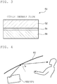
- FIG. 1 is a schematic partial sectional view for illustrating a head-up display apparatus according to one embodiment of the present invention.
- a head-up display apparatus 100 includes: a display unit 10 configured to output projection light; at least one reflector (in the illustrated example, one reflector) 20 configured to reflect the projection light; a housing 30, which has an opening portion 32, and which is configured to store the display unit 10 and the reflector 20 therein; a cover member 40 configured to cover the opening portion 32; and a polarizing plate 50 with a retardation layer, which is arranged on a housing inner side of the cover member 40.
- the one reflector 20 is arranged in the embodiment of FIG. 1
- two reflectors 20 and 22 may be arranged like a head-up display apparatus 101 illustrated in FIG. 2 .
- the display unit is typically, for example, a liquid crystal display apparatus.
- the liquid crystal display apparatus includes a polarizer, and hence projection light output from the liquid crystal display apparatus is linearly polarized light.
- the reflector 20 has, for example, a mirror portion and a mirror holder configured to hold the mirror portion at a predetermined position in the housing 30.
- the mirror portion may be a plane mirror, or may be a concave mirror.
- the concave mirror is adopted.
- the use of the concave mirror enables enlarged display of a video to be projected.
- the radius of curvature of the concave mirror may be appropriately set in accordance with, for example, a purpose and the size of the video to be projected.
- the reflector 22 may be, for example, a plane mirror (cold mirror) configured to transmit only an infrared ray and to reflect a visible ray and UV light.
- the housing 30 is a box-shaped member having an internal space capable of storing the display unit 10 and the reflectors 20 and 22.
- the housing 30 typically has the opening portion 32, and the projection light output from the display unit 10 through the opening portion 32 is discharged to the outside of the housing 30.
- the housing 30 may include any appropriate material.
- a preferred constituent material therefor is, for example, a material that hardly undergoes a temperature increase due to irradiation with sunlight, and that is easy to form. Specific examples of such material include an acrylic resin, an epoxy-based resin, a polyester-based resin, a urethane-based resin, a polyolefin-based resin, a fluorine-based resin, and a phenoxy-based resin.
- the housing 30 may be incorporated in a part of an automobile, or may be a member independent of an automobile. For example, a dashboard of an automobile may be used as the housing.
- the cover member 40 is a plate-shaped member configured to cover the opening portion 32 of the housing 30 so that dust does not enter the inside of the housing 30.
- the cover member 40 is typically transparent, and the projection light reflected from the reflector 20 passes the cover member 40 to be discharged to the outside of the housing 30. Details of the cover member are described later in the section B.
- the polarizing plate 50 with a retardation layer is typically bonded to the housing inner side of the cover member 40 via a pressure-sensitive adhesive. As illustrated in FIG. 3 , the polarizing plate 50 with a retardation layer includes a retardation layer 52 and a polarizer 54, and as required, a substrate 56 in the stated order from the cover member 40 side.
- the in-plane retardation Re(550) of the retardation layer 52 is from 100 nm to 200 nm. When the in-plane retardation of the retardation layer falls within such range, the layer has a function of converting linearly polarized light into circularly polarized light or elliptically polarized light.
- the projection light (linearly polarized light) output from the display unit (liquid crystal display apparatus) can be satisfactorily converted into circularly polarized light.
- the in-plane retardation Re(550) of the retardation layer 52 is from 220 nm to 320 nm.
- the layer has a function of converting the polarization direction of linearly polarized light.
- the projection light (linearly polarized light) output from the display unit (liquid crystal display apparatus) can be converted into linearly polarized light in the same direction as that of the transmission axis of a pair of polarized sunglasses.
- the arrangement of the polarizing plate with a retardation layer can improve the heat resistance of the head-up display apparatus because the polarizer of the polarizing plate with a retardation layer can suppress the incidence (passing) of the sunlight. Details of the polarizing plate with a retardation layer are described later in the section C.
- the term "Re( ⁇ )" as used herein refers to the in-plane retardation of a film measured at 23°C with light having a wavelength of ⁇ nm.
- Re(550) refers to the in-plane retardation of the film measured at 23°C with light having a wavelength of 550 nm.
- the direction of the absorption axis of the polarizing plate 50 with a retardation layer is typically set to a direction substantially perpendicular to the polarization direction of the projection light (typically linearly polarized light).
- the expressions “substantially perpendicular” and “approximately perpendicular” as used herein each include a case in which an angle formed between two directions is 90° ⁇ 7°, and the angle is preferably 90° ⁇ 5°, more preferably 90° ⁇ 3°.
- the expressions “substantially parallel” and “approximately parallel” each include a case in which an angle formed between two directions is 0° ⁇ 7°, and the angle is preferably 0° ⁇ 5°, more preferably 0° ⁇ 3°.
- the simple expression “perpendicular” or “parallel” as used herein may include a state in which two directions are substantially perpendicular, or substantially parallel, to each other.
- the head-up display apparatus is configured so that the angle of reflection ⁇ of the projection light output from the housing 30 through the opening portion 32 with respect to a windshield 60 is 30° or less, or is 40° or more.
- a head-up display apparatus that is excellent in viewability when a displayscreenis viewed through a pair of polarized sunglasses, and that is excellent in heat resistance can be achieved by a synergistic effect with the effect of the polarizing plate with a retardation layer described above.
- the angle of reflection ⁇ is preferably from 2° to 25° or from 45° to 89°, more preferably from 5° to 20° or from 55° to 85°.
- the angle of reflection ⁇ can be controlled by adjusting the angle of the reflector 20.
- the mirror holder only needs to be configured so that its angle can be adjusted.
- the mirror holder has, for example, a shaft whose peripheral surface is connected to the rear surface of the mirror portion, and a controlling portion connected to an end portion of the shaft.
- the angle of the mirror portion changes following the rotation of the shaft, and hence the angle of the mirror portion can be indirectly adjusted through the control of the rotation of the shaft by the controlling portion.
- the angle of the mirror portion may typically be adjusted in accordance with the shape of the windshield. As is apparent from FIG. 4 , the angle of reflection and angle of incidence of the projection light have the same value.
- the cover member 40 is typically transparent.
- transparent as used herein means that the member has a property of transmitting visible light having a wavelength of from 360 nm to 830 nm.
- transparent includes : a case in which the member is substantially free from absorbing visible light, and transmits light having any wavelength in a visible light region (colorless transparent) ; and a case in which the member absorbs light beams having some wavelengths in the visible light region, and transmits light having a wavelength except the wavelengths (colored transparent).
- the cover member 40 is preferably colorless transparent.
- the total light transmittance of the cover member is preferably 50% or more, more preferably 70% or more, still more preferably 90% or more.
- the total light transmittance is a value measured in conformity with JIS K 7375.
- the surface shape of the cover member may be appropriately set in accordance with the shape of the opening portion 32 .
- the portion of the cover member configured to cover the opening portion may include only a flat surface or only a curved surface, or the portion configured to cover the opening portion may include a plurality of flat surfaces and/or a plurality of curved surfaces.
- the surface shape of the cover member typically includes only a flat surface or only a curved surface. In the illustrated example, a cover member whose portion configured to cover the opening portion includes only a curved surface is used.
- the thickness of the cover member may be, for example, from 10 ⁇ m to 1,000 ⁇ m.
- the cover member is excessively thick, there is a risk in that the transmittance of the projection light reduces (the light loss of the projection light increases), and moreover, the reduction serves as a cause for the occurrence of a double image.
- the cover member is excessively thin, there is a risk in that its mechanical strength becomes insufficient, and hence its covering function becomes insufficient.
- the cover member may include any appropriate transparent material. Typical examples thereof include a resin and glass.
- the resin include: ester-based resins, such as polyethylene terephthalate and polyethylene naphthalate; cellulose-based resins, such as diacetyl cellulose and triacetyl cellulose; polycarbonate-based resins, such as bisphenol A-based polycarbonate; acrylic resins, such as polymethyl methacrylate; acrylic resins, such as a lactone-modified acrylic resin; styrene-based resins, such as polystyrene and an acrylonitrile-styrene copolymer; olefin-based resins, such as polyethylene, polypropylene, a polyolefin having a cyclic structure or a norbornene structure, and an ethylene-propylene copolymer; vinyl chloride-based resins; amide-based resins, such as aromatic polyamide; imide-based resins; sulfone-based resin
- any appropriate polarizer may be adopted as the polarizer. Typical examples thereof include an iodine-based polarizer and a lyotropic liquid crystal polarizer.
- a resin film for forming the iodine-based polarizer may be a single-layer resin film, or may be produced by using a laminate of two or more layers.
- the polarizer formed of a single-layer resin film include: a polarizer obtained by subjecting a hydrophilic polymer film, such as a polyvinyl alcohol (PVA) -based resin film, a partially formalized PVA-based resin film, or an ethylene-vinyl acetate copolymer-based partially saponified film, to dyeing treatment with a dichroic substance, such as iodine or a dichroic dye, and stretching treatment; and a polyene-based alignment film, such as a dehydration-treated product of PVA or a dehydrochlorination-treated product of polyvinyl chloride.
- a polarizer obtained by dyeing the PVA-based resin film with iodine and uniaxially stretching the resultant is preferably used because the polarizer is excellent in optical characteristics.
- the dyeing with iodine is performed by, for example, immersing the PVA-based resin film in an aqueous solution of iodine.
- the stretching ratio of the uniaxial stretching is preferably from 3 times to 7 times .
- the stretching may be performed after the dyeing treatment, or may be performed while the dyeing is performed.
- the dyeing may be performed after the stretching has been performed.
- the PVA-based resin film is subjected to swelling treatment, cross-linking treatment, washing treatment, drying treatment, or the like as required. For example, when the PVA-based resin film is immersed in water to be washed with water before the dyeing, contamination or an antiblocking agent on the surface of the PVA-based resin film can be washed off. In addition, the PVA-based resin film is swollen and hence dyeing unevenness or the like can be prevented.
- a specific example of the polarizer obtained by using a laminate is a polarizer obtained by using a laminate of a resin substrate and a PVA-based resin layer (PVA-based resin film) laminated on the resin substrate or a laminate of a resin substrate and a PVA-based resin layer formed on the resin substrate through application.
- the polarizer obtained by using the laminate of the resin substrate and the PVA-based resin layer formed on the resin substrate through application may be produced, for example, by: applying a PVA-based resin solution to the resin substrate; drying the solution to form the PVA-based resin layer on the resin substrate, to thereby provide the laminate of the resin substrate and the PVA-based resin layer; and stretching and dyeing the laminate to turn the PVA-based resin layer into the polarizer.
- the stretching typically includes stretching of the laminate under a state in which the laminate is immersed in an aqueous solution of boric acid. Further, the stretching may further include in-air stretching of the laminate at high temperature (e.g., 95°C or more) before the stretching in the aqueous solution of boric acid as required.
- the resultant laminate of the resin substrate and the polarizer may be used as it is (i.e., the resin substrate may be used as a protective layer for the polarizer).
- a product obtained as described below may be used: the resin substrate is peeled from the laminate of the resin substrate and the polarizer, and any appropriate protective layer in accordance with purposes is laminated on the peeling surface. Details of such method of producing the polarizer are described in, for example, JP 2012-73580 A , the description of which is incorporated herein by reference in its entirety.
- the lyotropic liquid crystal polarizer is excellent in heat resistance, and hence can result in a further improvement in heat resistance of the head-up display apparatus.
- the lyotropic liquid crystal polarizer contains, for example, an aromatic disazo compound represented by the following formula (1): in the formula (1), Q 1 represents a substituted or unsubstituted aryl group, Q 2 represents a substituted or unsubstituted arylene group, R 1 s each independently represent a hydrogen atom, a substituted or unsubstituted alkyl group, a substituted or unsubstituted acetyl group, a substituted or unsubstituted benzoyl group, or a substituted or unsubstituted phenyl group, M represents a counterion, "m” represents an integer of from 0 to 2, and “n” represents an integer of from 0 to 6, provided that at least one of "m” or “n” does not represent 0, a relationship of 1 ⁇ m+n ⁇ 6 is satisfied,
- OH, (NHR 1 ) m , and (SO 3 M) n represented in the formula (1) may each be bonded to any one of the seven substitution sites of a naphthyl ring.
- the azo group is preferably bonded to the 1-position or 2-position of the naphthyl group.
- R 1 represents preferably a hydrogen atom, a substituted or unsubstituted alkyl group, or a substituted or unsubstituted acetyl group, more preferably a hydrogen atom.
- the substituted or unsubstituted alkyl group is, for example, a substituted or unsubstituted alkyl group having 1 to 6 carbon atoms.
- M (the counterion) of the formula (1) include: a hydrogen ion; an ion of an alkali metal, such as Li, Na, K, or Cs; an ion of an alkaline earth metal, such as Ca, Sr, or Ba; any other metal ion; an ammonium ion that may be substituted with an alkyl group or a hydroxyalkyl group; and a salt of an organic amine.
- the metal ion include Ni + , Fe 3+ , Cu 2+ , Ag + , Zn 2+ , Al 3+ , Pd 2+ , Cd 2+ , Sn 2+ , Co 2+ , Mn 2+ , and Ce 3+ .
- Examples of the organic amine include: an alkylamine having 1 to 6 carbon atoms; an alkylamine that has 1 to 6 carbon atoms and has a hydroxyl group; and an alkylamine that has 1 to 6 carbon atoms and has a carboxyl group.
- the respective Ms may be identical to or different from each other.
- M of SO 3 M in the formula (1) represents a cation that is divalent or more, the cation maybe bonded to SO 3 - of any other adjacent azo-based compound molecule to form a supramolecular associate.
- n of the formula (1) preferably represents 1 or 2.
- naphthyl group of the formula (1) include groups represented by the formula (a) to the formula (1) below.
- R 1 s and Ms of the formula (a) to the formula (1) are as described for the formula (1).
- the aryl group represented by Q 1 in the formula (1) is, for example, a fused ring group in which two or more benzene rings are fused to each other, such as a naphthyl group, as well as a phenyl group.
- the arylene group represented by Q 2 is, for example, a fused ring group in which two or more benzene rings are fused to each other, such as a naphthylene group, as well as a phenylene group.
- the aryl group represented by Q 1 or the arylene group represented by Q 2 may have a substituent, or may be free of any substituent. Irrespective of whether the aryl group or the arylene group is substituted or unsubstituted, the aromatic disazo compound represented by the formula (1), which has a polar group, is excellent in solubility in an aqueous solvent.
- examples of the substituent include: an alkyl group having 1 to 6 carbon atoms; an alkoxy group having 1 to 6 carbon atoms; an alkylamino group having 1 to 6 carbon atoms; a phenylamino group; an acylamino group having 1 to 6 carbon atoms; a hydroxyalkyl group having 1 to 6 carbon atoms, such as a dihydroxypropyl group; a carboxyl group, such as a COOM group; a sulfonic acid group, such as an SO 3 M group; a hydroxyl group; a cyano group; a nitro group; an amino group; and a halogeno group.
- the substituent is preferably one selected from an alkoxy group having 1 to 6 carbon atoms, a hydroxyalkyl group having 1 to 6 carbon atoms, a carboxyl group, a sulfonic acid group, and a nitro group.
- the aromatic disazo compound having any such substituent is particularly excellent in water solubility.
- the aryl group or the arylene group may be substituted with one kind of those substituents, or may be substituted with two or more kinds thereof. In addition, the aryl group or the arylene group may be substituted with the substituent at any ratio.
- Q 1 of the formula (1) represents preferably a substituted or unsubstituted phenyl group, more preferably a phenyl group having the above-mentioned substituent.
- Q 2 of the formula represents preferably a substituted or unsubstituted naphthylene group, more preferably a naphthylene group having the above-mentioned substituent, particularly preferably a 1, 4-naphthylene group having the above-mentioned substituent.
- An aromatic disazo compound in which Q 1 of the formula (1) represents a substituted or unsubstituted phenyl group, and Q 2 thereof represents a substituted or unsubstituted 1, 4-naphthylene group is represented by the following formula (2).
- R 1 , M, "m”, and “n” are as described for the formula (1).
- a and B represent substituents, and "a" and “b” represent their numbers of substitutions.
- a and B each independently represent an alkyl group having 1 to 6 carbon atoms, an alkoxy group having 1 to 6 carbon atoms, an alkylamino group having 1 to 6 carbon atoms, a phenylamino group, an acylamino group having 1 to 6 carbon atoms, a hydroxyalkyl group having 1 to 6 carbon atoms, such as a dihydroxypropyl group, a carboxyl group, such as a COOM group, a sulfonic acid group, such as an SO 3 M group, a hydroxyl group, a cyano group, a nitro group, an amino group, or a halogeno group.
- an aromatic disazo compound represented by the following formula (3) is preferred.
- the OH group of the naphthyl group of the aromatic disazo compound represented by the formula (3) is bonded to a position (ortho position) adjacent to an azo group.
- R 1 , M, "m”, and “n” are as described for the formula (1), and A is as described for the formula (2).
- "p” represents an integer of from 0 to 4.
- "p” represents preferably 1 or 2, more preferably 1.
- the aromatic disazo compounds represented by the formulae (1) to (3) may each be synthesized in accordance with, for example, " Theoretical Production Dye Chemistry (Fifth Edition) " written by Yutaka Hosoda (published by Gihodo on July 15, 1968, p. 135 to 152 ).
- the aromatic disazo compound represented by the formula (3) may be synthesized by: subjecting an aniline derivative and a naphthalenesulfonic acid derivative to diazotization and a coupling reaction to provide a monoazo compound; then diazotizing the monoazo compound; and subjecting the resultant to a coupling reaction with a 1-amino-8-naphtholsulfonic acid derivative.
- the lyotropic liquid crystal polarizer may be produced by, for example, a method including a step B and a step C described below. As required, a step A may be performed before the step B, and a step D may be performed after the step C:
- the step A is a step of subjecting the surface of the substrate to the alignment treatment to impart an alignment-regulating force to the surface of the substrate.
- a method of imparting the alignment-regulating force is, for example, (a) a method including subjecting the surface of the substrate to rubbing treatment, (b) a method including forming a film of polyimide or the like on the surface of the substrate, and subjecting the surface of the formed film to rubbing treatment to form an alignment film, or (c) a method including forming a film formed of a photoreactive compound on the surface of the substrate, and irradiating the formed film with light to form an alignment film.
- a polarizing plate with a retardation layer having the alignment film between its substrate and polarizer is produced.
- the substrate may be used as it is (in this case, the substrate may function as a protective layer for the polarizer), or the following may be performed: the substrate is peeled, and any appropriate protective film is arranged on the peeling surface.
- the step B is a step of forming the coating film through the use of the coating liquid.
- the coating liquid contains the aromatic disazo compound and a solvent in which the aromatic disazo compound is dissolved or dispersed.
- the coating liquid is obtained by dissolving or dispersing the aromatic disazo compound in the solvent.
- any other polymer except the aromatic disazo compound and/or an additive may be added to the solvent.
- any appropriate solvent may be used as the solvent in which the aromatic disazo compound is dissolved or dispersed.
- An aqueous solvent is preferred.
- the aqueous solvent include water, a hydrophilic solvent, and a mixed solvent of water and the hydrophilic solvent.
- the hydrophilic solvent is a solvent that dissolves in water in an approximately uniform manner.
- the hydrophilic solvent include: alcohols, such as methanol and isopropyl alcohol; glycols, such as ethylene glycol; cellosolves, such as methyl cellosolve and ethyl cellosolve; ketones, such as acetone and methyl ethyl ketone; and esters, such as ethyl acetate.
- water or a mixed solvent of water and a hydrophilic solvent is preferably used.
- the aromatic disazo compound represented by the formula (1) is an organic compound having lyotropic liquid crystallinity. Accordingly, when the temperature of the coating liquid, the concentration of the aromatic disazo compound therein, or the like is changed, the liquid shows a lyotropic liquid crystal phase.
- the lyotropic liquid crystal phase is produced by the formation of a supramolecular associate by the aromatic disazo compound in the liquid.
- the lyotropic liquid crystal phase may be confirmed and identified by an optical pattern observed with a polarizing microscope.
- the supramolecular associate is one large composite formed by the bonding of a plurality of aromatic disazo compound molecules through a hydrogen bond or the like.
- the concentration of the aromatic disazo compound in the coating liquid is preferably adjusted so that the liquid shows a liquid crystal phase.
- the concentration of the aromatic disazo compound in the coating liquid is typically from 0.05 wt% to 50 wt%, preferably from 0.5 wt% to 40 wt%, more preferably from 1 wt% to 10 wt%.
- the pH of the coating liquid is adjusted to an appropriate value.
- the pH of the coating liquid is preferably from about 2 to about 10, more preferably from about 6 to about 8.
- the temperature of the coating liquid is adjusted to preferably from 10°C to 40°C, more preferably from 15°C to 30°C.
- the application of the coating liquid onto the substrate results in the formation of the coating film.
- the aromatic disazo compound is aligned in a predetermined direction by the alignment-regulating force of the substrate.
- An application method including using any appropriate coater may be adopted as a method of applying the coating liquid.
- the coater include a bar coater, a roll coater, a spin coater, a comma coater, a gravure coater, an air knife coater, and a die coater.
- the step C is a step of forming the polarizer that is a dried coating film.
- the formation of the polarizer that is a dried coating film on the substrate provides a polarizing plate including the substrate and the polarizer.
- a method of drying the coating film is, for example, natural drying or forced drying.
- the forced drying include drying under reduced pressure, heat drying, and heat drying under reduced pressure.
- the natural drying is preferably used.
- the drying time of the coating film may be appropriately set in accordance with the drying temperature thereof and the kind of the solvent. In the case of, for example, the natural drying, the drying time is preferably from 1 second to 120 minutes, more preferably from 10 seconds to 5 minutes .
- the drying temperature is preferably from 10°C to 100°C, more preferably from 10°C to 90°C, particularly preferably from 10°C to 80°C.
- the drying temperature means not the temperature of the surface or inside of the coating film but the temperature of the atmosphere under which the coating film is dried.
- the step D is a step of bringing a water-resistant treatment liquid into contact with the polarizer to impart water resistance to the polarizer.
- Any appropriate method may be adopted as a method of bringing the polarizer into contact with the water-resistant treatment liquid.
- the contact method include methods such as (a) the application of the water-resistant treatment liquid to the surface of the polarizer, (b) the immersion of the polarizing plate (polarizer) in a bath filled with the water-resistant treatment liquid, and (c) the passing of the polarizing plate (polarizer) through a bath filled with the water-resistant treatment liquid.
- the application of the water-resistant treatment liquid described in the (a) may be performed with, for example, any appropriate coater or spray.
- the water-resistant treatment liquid contains, for example, a cross-linking agent having a function of cross-linking an organic dye and a solvent in which the cross-linking agent is dissolved or dispersed.
- the cross-linking agent may be, for example, an organic nitrogen compound
- the solvent may be, for example, an aqueous solvent.
- an acyclic organic nitrogen compound having two or more cationic groups (preferably cationic groups each containing a nitrogen atom) in a molecule thereof is used as the organic nitrogen compound.
- acyclic organic nitrogen compound examples include: an aliphatic diamine, such as an alkylene diamine, or a salt thereof; an aliphatic triamine, such as an alkylene triamine, or a salt thereof; an aliphatic tetraamine, such as an alkylene tetraamine, or a salt thereof; an aliphatic pentaamine, such as an alkylene pentaamine, or a salt thereof; and an aliphatic ether diamine, such as an alkylene ether diamine, or a salt thereof.
- the solvent described for the step B may be used as the aqueous solvent.
- the concentration of the cross-linking agent in the water-resistant treatment liquid is preferably from 1 mass% to 50 mass%, more preferably from 5 mass% to 30 mass%.
- the thickness of the iodine-based polarizer is preferably 15 ⁇ m or less, more preferably 13 ⁇ m or less, still more preferably 10 ⁇ m or less, particularly preferably 8 ⁇ m or less.
- the lower limit of the thickness of the iodine-based polarizer is 2 ⁇ m in one embodiment, and is 3 ⁇ m in another embodiment.
- the thickness of the lyotropic liquid crystal polarizer is preferably 1,000 nm or less, more preferably 700 nm or less, particularly preferably 500 nm or less.
- the lower limit of the thickness of the lyotropic liquid crystal polarizer is preferably 100 nm, more preferably 200 nm, particularly preferably 300 nm. When the thickness of the polarizer falls within such range, the projection light can be satisfactorily discharged from the housing, and the incidence (passing) of the sunlight into the housing can be suppressed.
- the polarizer preferably shows absorption dichroism at any wavelength in the wavelength range of from 380 nm to 780 nm.
- the single layer transmittance of the polarizer is preferably from 35.0% to 50.0%, more preferably from 40.0% to 45.0%.
- the polarization degree of the polarizer is 88% or more, and is preferably 89% or more, more preferably 90% or more.
- the retardation layer has the function of converting linearly polarized light into circularly polarized light or elliptically polarized light, or the function of converting the polarization direction of linearly polarized light.
- the refractive index characteristic of the retardation layer typically shows a relationship of nx>ny.
- the in-plane retardation Re(550) of the retardation layer is from 100 nm to 200 nm, preferably from 110 nm to 170 nm, more preferably from 130 nm to 150 nm. In this case, the retardation layer can satisfactorily exhibit the function of converting linearly polarized light into circularly polarized light or elliptically polarized light.
- the in-plane retardation Re (550) of the retardation layer is from 220 nm to 320 nm, preferably from 240 nm to 300 nm, more preferably from 260 nm to 280 nm.
- the retardation layer can satisfactorily exhibit the function of converting the polarization direction of linearly polarized light.
- a retardation film having appropriate elliptical polarization performance or appropriate performance of converting the direction of linearly polarized light can be obtained with excellent productivity and at reasonable cost.
- a polarizing plate with a retardation layer capable of securing satisfactory viewability even when a display screen is viewed through a polarized lens, such as a pair of polarized sunglasses, can be obtained with excellent productivity and at reasonable cost.
- the retardation layer shows any appropriate refractive index ellipsoid as long as the layer has the relationship of nx>ny.
- the refractive index ellipsoid of the retardation layer preferably shows a relationship of nx>ny ⁇ nz.
- the Nz coefficient of the retardation layer is preferably from 1 to 2, more preferably from 1 to 1.5, still more preferably from 1 to 1.3.
- the Nz coefficient is calculated from the equation "Rth( ⁇ )/Re( ⁇ )".
- the Re( ⁇ ) is as described above .
- the polarizer and the retardation layer are laminated so that the absorption axis of the polarizer and the slow axis of the retardation layer form a predetermined angle .
- an angle formed between the absorption axis of the polarizer and the slow axis of the retardation layer is preferably from 35° to 55°, more preferably from 38° to 52°, still more preferably from 40° to 50°, particularly preferably from 42° to 48°, further particularly preferably around 45°.
- the angle formed between the absorption axis of the polarizer and the slow axis of the retardation layer is preferably from 12.5° to 32.5°, more preferably from 15.5° to 29.5°, still more preferably from 17.5° to 27.5°, particularly preferably from 19.5° to 25.5°, further particularly preferably around 22.5°.
- the retardation layer is arranged on a side closer to the cover member with respect to the polarizer so as to satisfy such axial relationship, in the case where a display screen is viewed through a polarized lens, such as a pair of polarized sunglasses, excellent viewability can be achieved.
- the retardation layer includes any appropriate retardation film capable of satisfying such optical characteristics as described above.
- a resin for forming the retardation film include a cyclic olefin-based resin, a polycarbonate-based resin, a cellulose-based resin, a polyester-based resin, a polyvinyl alcohol-based resin, a polyamide-based resin, a polyimide-based resin, a polyether-based resin, a polystyrene-based resin, and an acrylic resin.
- the polycarbonate-based resin may be suitably used, and when the retardation layer includes a resin film showing a flat wavelength dispersion characteristic, the cyclic olefin-based resin may be suitably used.
- the cyclic olefin-based resin is a collective term for resins each obtained by polymerizing a cyclic olefin as a polymerization unit, and examples thereof include resins described in, for example, JP 01-240517 A , JP 03-14882 A , and JP 03-122137 A .
- ring-opening (co)polymer of a cyclic olefin examples thereof include a ring-opening (co)polymer of a cyclic olefin, an addition polymer of a cyclic olefin, and a copolymer (typically a random copolymer) of a cyclic olefin and an ⁇ -olefin, such as ethylene or propylene, and graft modified products obtained by modifying those polymers with an unsaturated carboxylic acid or a derivative thereof, and hydrogenated products thereof.
- a ring-opening (co)polymer of a cyclic olefin an addition polymer of a cyclic olefin
- a copolymer typically a random copolymer of a cyclic olefin and an ⁇ -olefin, such as ethylene or propylene
- the polycarbonate resin preferably contains: a structural unit derived from a fluorene-based dihydroxy compound; a structural unit derived from an isosorbide-based dihydroxy compound; and a structural unit derived from at least one dihydroxy compound selected from the group consisting of an alicyclic diol, an alicyclic dimethanol, di-, tri-, or polyethylene glycol, and an alkylene glycol or spiroglycol.
- the polycarbonate resin more preferably contains: a structural unit derived from a fluorene-based dihydroxy compound; a structural unit derived from an isosorbide-based dihydroxy compound; and a structural unit derived from an alicyclic dimethanol and/or a structural unit derived from di-, tri-, or polyethylene glycol.
- the polycarbonate resin still more preferably contains: a structural unit derived from a fluorene-based dihydroxy compound; a structural unit derived from an isosorbide-based dihydroxy compound; and a structural unit derived from di-, tri-, or polyethylene glycol.
- the polycarbonate resin may contain a structural unit derived from any other dihydroxy compound as required. Details of the polycarbonate resin that may be suitably used in the present invention are described in, for example, JP 2014-10291 A and JP 2014-26266 A , the descriptions of which are incorporated herein by reference.
- cellulose-based resin examples include cellulose (di or tri)acetate, cellulose propionate, cellulose butyrate, cellulose acetate propionate, cellulose acetate butyrate, cellulose acetate phthalate, and cellulose phthalate.
- the retardation layer (retardation film) is typically produced by stretching a resin film formed from any such resin as described above in at least one direction.
- any appropriate method may be adopted as a method of forming the resin film.
- a melt extrusion method e.g., a T-die molding method
- a cast coating method e.g., a casting method
- a calendar molding method e.g., a hot press method
- a co-extrusion method e.g., a co-melting method
- multilayer extrusion e.g., a T-die molding method
- an inflation molding method e.g., a T-die molding method, a casting method, and an inflation molding method are preferably used.
- the thickness of the resin film may be set to any appropriate value depending on, for example, the desired optical characteristics and stretching conditions to be described later.
- the thickness is preferably from 50 ⁇ m to 300 ⁇ m, more preferably from 80 ⁇ m to 250 ⁇ m.
- any appropriate stretching method and stretching conditions may be adopted for the stretching.
- one kind of various stretching methods such as free-end stretching, fixed-end stretching, free-end shrinkage, and fixed-end shrinkage, may be employed alone, or two or more kinds thereof may be employed simultaneously or sequentially.
- the stretching direction the stretching may be performed in various directions or dimensions, such as a horizontal direction, a vertical direction, a thickness direction, and a diagonal direction.
- the temperature at which the stretching is performed preferably falls within the range of the glass transition temperature (Tg) of the resin film ⁇ 20°C.
- a retardation film (consequently a retardation layer) having the desired optical characteristics (e.g., a refractive index ellipsoid, an in-plane retardation, and an Nz coefficient) can be obtained by appropriately selecting the stretching method and stretching conditions.
- the desired optical characteristics e.g., a refractive index ellipsoid, an in-plane retardation, and an Nz coefficient
- the retardation layer is produced by subjecting a resin film to uniaxial stretching or fixed-end uniaxial stretching.
- a specific example of the uniaxial stretching is a method involving stretching the resin film in its lengthwise direction (longitudinal direction) while running the resin film in its elongate direction.
- Another specific example of the uniaxial stretching is a method involving stretching the resin film in its lateral direction using a tenter. The stretching ratio is preferably from 10% to 500%.
- the retardation layer is produced by continuously subjecting a resin film having an elongate shape to oblique stretching in the direction of an angle ⁇ with respect to its elongate direction.
- a stretched film having an elongate shape and having an alignment angle that is an angle ⁇ with respect to the elongate direction of the film is obtained, and for example, its lamination with the polarizer can be performed by a roll-to-roll process.
- the angle ⁇ corresponds to such angle formed between the absorption axis of the polarizer and the slow axis of the retardation layer as described above.
- a stretching machine to be used for the oblique stretching for example, there is given a tenter stretching machine capable of applying feeding forces or tensile forces, or take-up forces, having different speeds on left and right sides in a lateral direction and/or a longitudinal direction.
- the tenter stretching machine include a lateral uniaxial stretching machine and a simultaneous biaxial stretching machine, and any appropriate stretching machine may be used as long as the resin film having an elongate shape can be continuously subjected to the oblique stretching.
- the thickness of the stretched film is preferably from 20 ⁇ m to 80 ⁇ m, more preferably from 30 ⁇ m to 60 ⁇ m.
- the substrate is an optional constituent of the polarizing plate with a retardation layer, and is arranged as required.
- the substrate includes any appropriate film that may be used as a protective film for the polarizer.
- cellulose-based resins such as triacetylcellulose (TAC)
- TAC triacetylcellulose
- transparent resins such as polyester-based, polyvinyl alcohol-based, polycarbonate-based, polyamide-based, polyimide-based, polyether sulfone-based, polysulfone-based, polystyrene-based, polynorbornene-based, polyolefin-based, cyclic olefin-based, (meth)acrylic, and acetate-based resins.
- thermosetting resins or UV-curable resins such as (meth)acrylic, urethane-based, (meth)acrylic urethane-based, epoxy-based, and silicone-based resins.
- glassy polymers such as a siloxane-based polymer.
- a polymer film described in JP 2001-343529 A ( WO 01/37007 A1 ) may be used.
- a resin composition containing a thermoplastic resin having a substituted or unsubstituted imide group on a side chain thereof, and a thermoplastic resin having a substituted or unsubstituted phenyl group and a nitrile group on side chains thereof may be used as a material for the film, and the composition is, for example, a resin composition containing an alternating copolymer formed of isobutene and N-methylmaleimide, and an acrylonitrile-styrene copolymer.
- the polymer film may be, for example, an extrudate of the resin composition.
- the (meth)acrylic resin or the cyclic olefin-based resin may be preferably used.
- the glass transition temperature (Tg) of the (meth)acrylic resin is preferably 115°C or more, more preferably 120°C or more, still more preferably 125°C or more, particularly preferably 130°C or more. This is because the resin may be excellent in durability.
- the upper limit value of the Tg of the (meth)acrylic resin is not particularly limited, the upper limit is preferably 170°C or less from the viewpoint of, for example, its formability.
- any appropriate (meth)acrylic resin may be adopted as the (meth) acrylic resin to the extent that the effects of the present invention are not impaired.
- examples thereof include poly(meth)acrylic acid esters, such as polymethyl methacrylate, a methyl methacrylate-(meth)acrylic acid copolymer, a methyl methacrylate-(meth)acrylic acid ester copolymer, a methyl methacrylate-acrylic acid ester-(meth)acrylic acid copolymer, a methyl (meth)acrylate-styrene copolymer (e.g., an MS resin), and a polymer having an alicyclic hydrocarbon group (e.g., a methyl methacrylate-cyclohexyl methacrylate copolymer or a methyl methacrylate-norbornyl (meth)acrylate copolymer).
- poly(meth)acrylic acid esters such as polymethyl methacrylate, a methyl
- a poly-C 1-6 alkyl (meth) acrylate such as polymethyl (meth) acrylate
- a methyl methacrylate-based resin containing methyl methacrylate as a main component is more preferred.
- the (meth)acrylic resin examples include: ACRYPET VH and ACRYPET VRL20A manufactured by Mitsubishi Rayon Co., Ltd.; a (meth) acrylic resin described in JP 2004-70296 A , the resin having a ring structure in a molecule thereof; and a high-Tg (meth)acrylic resin obtained by intramolecular cross-linking or an intramolecular cyclization reaction.
- a (meth)acrylic resin having a lactone ring structure is particularly preferred as the (meth)acrylic resin because the resin has high heat resistance, high transparency, and high mechanical strength.
- Examples of the (meth)acrylic resin having a lactone ring structure include (meth) acrylic resins each having a lactone ring structure described in JP 2000-230016 A , JP 2001-151814 A , JP 2002-120326 A , JP 2002-254544 A , and JP 2005-146084 A .
- the (meth) acrylic resin having a lactone ring structure has a mass-average molecular weight (sometimes referred to as weight-average molecular weight) of preferably from 1,000 to 2,000,000, more preferably from 5,000 to 1,000,000, still more preferably from 10,000 to 500,000, particularly preferably from 50,000 to 500,000.
- mass-average molecular weight sometimes referred to as weight-average molecular weight
- the glass transition temperature (Tg) of the (meth) acrylic resin having a lactone ring structure is preferably 115°C or more, more preferably 125°C or more, still more preferably 130°C ormore, particularly preferably 135°C or more, most preferably 140°C or more. This is because the resin may be excellent in durability.
- the upper limit value of the Tg of the (meth)acrylic resin having a lactone ring structure is not particularly limited, the upper limit value is preferably 170°C or less from the viewpoint of, for example, its formability.
- (meth) acrylic refers to acrylic and/or methacrylic.
- the cyclic olefin-based resin is as described for the retardation film in the section C-2.
- the substrate having applied thereto the coating liquid containing the aromatic disazo compound may be used as it is as the substrate, or the following may be performed: the substrate is peeled, and such protective film as described above is bonded to the peeling surface.
- the substrate be optically isotropic .
- be optically isotropic means that the in-plane retardation Re(550) of the substrate is from 0 nm to 10 nm, and the thickness direction retardation Rth(550) thereof is from -10 nm to +10 nm.
- the thickness of the substrate is preferably from 20 ⁇ m to 80 ⁇ m, more preferably from 30 ⁇ m to 60 ⁇ m.
- the polarizing plate with a retardation layer may further have a hard coat layer and/or an antiblocking layer on the opposite side of the substrate to the polarizer as required.
- the hard coat layer is described in detail in, for example, JP 2007-171943 A .
- the antiblocking layer is described in detail in, for example, JP 2015-115171 A , JP 2015-141674 A , JP 2015-120870 A , and JP 2015-005272 A . The descriptions of those publications are incorporated herein by reference.
- the polarizer 54 and the retardation layer 52 are bonded to each other via any appropriate adhesion layer.
- the polarizer 54 and the substrate 56 are bonded to each other via any appropriate adhesion layer.
- the adhesion layer may be a pressure-sensitive adhesive layer, or may be an adhesive layer.
- a pressure-sensitive adhesive forming the pressure-sensitive adhesive layer may typically be an acrylic pressure-sensitive adhesive.
- An adhesive forming the adhesive layer may typically be an energy ray-curable adhesive.
- S-polarized light was caused to enter a laminate having the configuration "cover member/polarizing plate with a retardation layer", which was obtained in Example 1, or a laminate having the configuration "cover member/polarizing plate", which was obtained in Comparative Example 1, and the S-polarized light that had passed the laminate was reflected on a rectangular glass plate having a thickness of 1.3 mm (manufactured by Matsunami Glass Ind., Ltd., product name: "S200423”) at an angle of incidence in the range of from 30° to 80°, followed by the measurement of the reflectance of the P-polarized light of the reflected light with a spectroscopic ellipsometer (manufactured by J.A. Woollam, product name: "M-2000VI").
- the vibration direction of the S-polarized light to be caused to enter the laminate was set to be parallel to the transmission axis direction of the polarizer of the laminate.
- the reflectance of the P-polarized light for each angle of incidence is shown in Table 1 to be described later
- a norbornene-based resin film (manufactured by Zeon Corporation: product name: "ZEONOR ZF14-100") was prepared as a substrate, and the surface of the film was subjected to rubbing treatment and hydrophilic treatment (corona treatment).
- the aromatic disazo compound represented by the formula (4) was dissolved in ion-exchanged water to prepare a coating liquid having a concentration of 4 wt%.
- the coating liquid was applied to the surface of the substrate subjected to the rubbing treatment and the hydrophilic treatment with a bar coater (manufactured by Buschman: product name: "Mayer rod HS4"), and was naturally dried in a thermostatic chamber at 23°C to form a dried coating film (polarizer) on the surface of the substrate.
- the thickness of the polarizer was 300 nm.
- the laminate having the configuration "substrate/polarizer” was immersed in a water-resistant treatment liquid for 2 seconds.
- the laminate having the configuration "substrate/polarizer” and the retardation film were bonded to each other so that the polarizer and the retardation film faced each other.
- An acrylic pressure-sensitive adhesive manufactured by Nitto Denko Corporation, product name: "CS9861UA" was used in the bonding.
- the bonding was performed so that the absorption axis of the polarizer and the slow axis of the retardation film formed an angle of 45°.
- a polarizing plate with a retardation layer having the configuration "substrate/polarizer/retardation film (retardation layer)" was obtained.
- a polycarbonate-based resin sheet having a thickness of 300 ⁇ m (manufactured by Mitsubishi Gas Chemical Company, Inc.: product name: "MRF08U”) was used as a cover member.
- the cover member and the polarizing plate with a retardation layer were bonded to each other via an acrylic pressure-sensitive adhesive (manufactured by Nitto Denko Corporation: product name: "CS9862UA”) so that the cover member and the retardation layer faced each other.
- CS9862UA acrylic pressure-sensitive adhesive
- Example 1 A laminate having the configuration "cover member/polarizing plate” was produced in the same manner as in Example 1 except that no retardation layer was arranged. The resultant laminate was subjected to the same evaluation as that of Example 1. The results are shown in Table 1. Table 1 Reflectance (%) Angle of incidence 35° 45° 55° 65° 75° Example 1 2.4 1.1 0 1.2 9.6 Comparative Example 1 0 0 0 0 0 0
- the reflectances of the laminates of Examples increase at predetermined angles of incidence.
- the foregoing means that no blackout occurs when the image of any such head-up display apparatus is viewed through a pair of polarized sunglasses. That is, it is understood that according to Examples of the present invention, a head-up display apparatus that is excellent in viewability when a display screen is viewed through a pair of polarized sunglasses can be achieved.
- the head-up display apparatus may be suitably used in a vehicle including a windshield (typically an automobile).
Landscapes
- Physics & Mathematics (AREA)
- Engineering & Computer Science (AREA)
- Chemical & Material Sciences (AREA)
- General Physics & Mathematics (AREA)
- Optics & Photonics (AREA)
- Combustion & Propulsion (AREA)
- Transportation (AREA)
- Mechanical Engineering (AREA)
- Organic Chemistry (AREA)
- Polarising Elements (AREA)
- Instrument Panels (AREA)
- Liquid Crystal (AREA)
Priority Applications (1)
| Application Number | Priority Date | Filing Date | Title |
|---|---|---|---|
| EP23215231.4A EP4309944A3 (fr) | 2017-10-19 | 2018-10-16 | Dispositif d'affichage tête haute |
Applications Claiming Priority (3)
| Application Number | Priority Date | Filing Date | Title |
|---|---|---|---|
| JP2017202605 | 2017-10-19 | ||
| JP2018194389A JP7253893B2 (ja) | 2017-10-19 | 2018-10-15 | ヘッドアップディスプレイ装置 |
| PCT/JP2018/038448 WO2019078191A1 (fr) | 2017-10-19 | 2018-10-16 | Dispositif d'affichage tête haute |
Related Child Applications (2)
| Application Number | Title | Priority Date | Filing Date |
|---|---|---|---|
| EP23215231.4A Division EP4309944A3 (fr) | 2017-10-19 | 2018-10-16 | Dispositif d'affichage tête haute |
| EP23215231.4A Division-Into EP4309944A3 (fr) | 2017-10-19 | 2018-10-16 | Dispositif d'affichage tête haute |
Publications (3)
| Publication Number | Publication Date |
|---|---|
| EP3699671A1 true EP3699671A1 (fr) | 2020-08-26 |
| EP3699671A4 EP3699671A4 (fr) | 2021-06-16 |
| EP3699671B1 EP3699671B1 (fr) | 2024-02-07 |
Family
ID=66627733
Family Applications (1)
| Application Number | Title | Priority Date | Filing Date |
|---|---|---|---|
| EP18869226.3A Active EP3699671B1 (fr) | 2017-10-19 | 2018-10-16 | Dispositif d'affichage tête haute |
Country Status (5)
| Country | Link |
|---|---|
| EP (1) | EP3699671B1 (fr) |
| JP (1) | JP7253893B2 (fr) |
| KR (1) | KR20200074107A (fr) |
| CN (1) | CN111226160A (fr) |
| TW (1) | TWI773841B (fr) |
Families Citing this family (1)
| Publication number | Priority date | Publication date | Assignee | Title |
|---|---|---|---|---|
| JP2023136360A (ja) * | 2022-03-16 | 2023-09-29 | 株式会社小糸製作所 | 画像投影装置 |
Family Cites Families (20)
| Publication number | Priority date | Publication date | Assignee | Title |
|---|---|---|---|---|
| US4961625A (en) * | 1987-09-18 | 1990-10-09 | Flight Dynamics, Inc. | Automobile head-up display system with reflective aspheric surface |
| JP2004109986A (ja) | 2003-08-28 | 2004-04-08 | Seiko Epson Corp | 液晶表示装置および電子機器 |
| JP2008070504A (ja) | 2006-09-13 | 2008-03-27 | Nippon Seiki Co Ltd | 表示装置 |
| JP2010152025A (ja) * | 2008-12-25 | 2010-07-08 | Nippon Seiki Co Ltd | 表示装置 |
| DE102011014145A1 (de) | 2010-12-23 | 2012-06-28 | Continental Automotive Gmbh | Head-up-Display für ein Kraftfahrzeug |
| JP2012194357A (ja) | 2011-03-16 | 2012-10-11 | Nitto Denko Corp | 偏光フィルム、コーティング液、及び画像表示装置 |
| JP6027727B2 (ja) | 2011-09-09 | 2016-11-16 | 矢崎総業株式会社 | 車両用表示装置 |
| JP2014044244A (ja) | 2012-08-24 | 2014-03-13 | Asahi Kasei E-Materials Corp | 映像表示装置 |
| JP2015222337A (ja) | 2014-05-23 | 2015-12-10 | 日本精機株式会社 | 表示装置 |
| JP2016012124A (ja) * | 2014-06-06 | 2016-01-21 | 日東電工株式会社 | 投影装置及び車 |
| US9606355B2 (en) * | 2014-09-29 | 2017-03-28 | Honeywell International Inc. | Apparatus and method for suppressing double images on a combiner head-up display |
| CN107003526A (zh) | 2015-03-19 | 2017-08-01 | 松下知识产权经营株式会社 | 平视显示器 |
| JP6308162B2 (ja) * | 2015-04-03 | 2018-04-11 | 株式会社デンソー | ヘッドアップディスプレイ装置 |
| US9823472B2 (en) * | 2015-07-17 | 2017-11-21 | Lg Electronics Inc. | Head up display for vehicle |
| JP6547492B2 (ja) | 2015-07-28 | 2019-07-24 | 日本精機株式会社 | ヘッドアップディスプレイ装置 |
| JP6595250B2 (ja) * | 2015-08-06 | 2019-10-23 | 株式会社ポラテクノ | ヘッドアップディスプレイ装置 |
| JP6589146B2 (ja) | 2015-12-01 | 2019-10-16 | パナソニックIpマネジメント株式会社 | ヘッドアップディスプレイ、およびヘッドアップディスプレイを搭載した移動体 |
| JP6743385B2 (ja) * | 2015-12-25 | 2020-08-19 | 住友ベークライト株式会社 | カバー部材 |
| CN106168710A (zh) * | 2016-09-28 | 2016-11-30 | 乐视控股(北京)有限公司 | 抬头显示系统及具有抬头显示系统的汽车 |
| JP7064281B2 (ja) | 2016-10-26 | 2022-05-10 | 日東電工株式会社 | 投影装置、及び自動車 |
-
2018
- 2018-10-15 JP JP2018194389A patent/JP7253893B2/ja active Active
- 2018-10-16 EP EP18869226.3A patent/EP3699671B1/fr active Active
- 2018-10-16 KR KR1020207010417A patent/KR20200074107A/ko not_active Application Discontinuation
- 2018-10-16 CN CN201880067772.3A patent/CN111226160A/zh active Pending
- 2018-10-19 TW TW107136910A patent/TWI773841B/zh active
Also Published As
| Publication number | Publication date |
|---|---|
| TWI773841B (zh) | 2022-08-11 |
| JP2019079041A (ja) | 2019-05-23 |
| KR20200074107A (ko) | 2020-06-24 |
| TW201923418A (zh) | 2019-06-16 |
| EP3699671A4 (fr) | 2021-06-16 |
| JP7253893B2 (ja) | 2023-04-07 |
| CN111226160A (zh) | 2020-06-02 |
| EP3699671B1 (fr) | 2024-02-07 |
Similar Documents
| Publication | Publication Date | Title |
|---|---|---|
| US11966050B2 (en) | Head-up display apparatus | |
| EP3916467A1 (fr) | Dispositif d'affichage tête haute et son procédé de fabrication | |
| US11933979B2 (en) | Head-up display device | |
| EP3699671B1 (fr) | Dispositif d'affichage tête haute | |
| US11567315B2 (en) | Head-up display device | |
| JP2023059916A (ja) | ヘッドアップディスプレイ装置およびその製造方法 | |
| US11650419B2 (en) | Head-up display apparatus | |
| US11215821B2 (en) | Head-up display device | |
| WO2019093079A1 (fr) | Dispositif d'affichage tête haute | |
| WO2019078190A1 (fr) | Appareil d'affichage tête haute |
Legal Events
| Date | Code | Title | Description |
|---|---|---|---|
| STAA | Information on the status of an ep patent application or granted ep patent |
Free format text: STATUS: THE INTERNATIONAL PUBLICATION HAS BEEN MADE |
|
| PUAI | Public reference made under article 153(3) epc to a published international application that has entered the european phase |
Free format text: ORIGINAL CODE: 0009012 |
|
| STAA | Information on the status of an ep patent application or granted ep patent |
Free format text: STATUS: REQUEST FOR EXAMINATION WAS MADE |
|
| 17P | Request for examination filed |
Effective date: 20200331 |
|
| AK | Designated contracting states |
Kind code of ref document: A1 Designated state(s): AL AT BE BG CH CY CZ DE DK EE ES FI FR GB GR HR HU IE IS IT LI LT LU LV MC MK MT NL NO PL PT RO RS SE SI SK SM TR |
|
| AX | Request for extension of the european patent |
Extension state: BA ME |
|
| DAV | Request for validation of the european patent (deleted) | ||
| DAX | Request for extension of the european patent (deleted) | ||
| A4 | Supplementary search report drawn up and despatched |
Effective date: 20210519 |
|
| RIC1 | Information provided on ipc code assigned before grant |
Ipc: G02B 27/01 20060101AFI20210512BHEP Ipc: B60K 35/00 20060101ALI20210512BHEP |
|
| STAA | Information on the status of an ep patent application or granted ep patent |
Free format text: STATUS: EXAMINATION IS IN PROGRESS |
|
| 17Q | First examination report despatched |
Effective date: 20220502 |
|
| GRAP | Despatch of communication of intention to grant a patent |
Free format text: ORIGINAL CODE: EPIDOSNIGR1 |
|
| STAA | Information on the status of an ep patent application or granted ep patent |
Free format text: STATUS: GRANT OF PATENT IS INTENDED |
|
| INTG | Intention to grant announced |
Effective date: 20230831 |
|
| GRAS | Grant fee paid |
Free format text: ORIGINAL CODE: EPIDOSNIGR3 |
|
| GRAA | (expected) grant |
Free format text: ORIGINAL CODE: 0009210 |
|
| STAA | Information on the status of an ep patent application or granted ep patent |
Free format text: STATUS: THE PATENT HAS BEEN GRANTED |
|
| P01 | Opt-out of the competence of the unified patent court (upc) registered |
Effective date: 20231212 |
|
| AK | Designated contracting states |
Kind code of ref document: B1 Designated state(s): AL AT BE BG CH CY CZ DE DK EE ES FI FR GB GR HR HU IE IS IT LI LT LU LV MC MK MT NL NO PL PT RO RS SE SI SK SM TR |
|
| REG | Reference to a national code |
Ref country code: GB Ref legal event code: FG4D |
|
| REG | Reference to a national code |
Ref country code: CH Ref legal event code: EP |
|
| REG | Reference to a national code |
Ref country code: IE Ref legal event code: FG4D |
|
| REG | Reference to a national code |
Ref country code: DE Ref legal event code: R096 Ref document number: 602018065033 Country of ref document: DE |
|
| REG | Reference to a national code |
Ref country code: LT Ref legal event code: MG9D |