EP3696880B1 - Separator und lithiumbatterie damit - Google Patents
Separator und lithiumbatterie damit Download PDFInfo
- Publication number
- EP3696880B1 EP3696880B1 EP20157052.0A EP20157052A EP3696880B1 EP 3696880 B1 EP3696880 B1 EP 3696880B1 EP 20157052 A EP20157052 A EP 20157052A EP 3696880 B1 EP3696880 B1 EP 3696880B1
- Authority
- EP
- European Patent Office
- Prior art keywords
- layer
- separator
- particles
- binder
- range
- Prior art date
- Legal status (The legal status is an assumption and is not a legal conclusion. Google has not performed a legal analysis and makes no representation as to the accuracy of the status listed.)
- Active
Links
Images


Classifications
-
- H—ELECTRICITY
- H01—ELECTRIC ELEMENTS
- H01M—PROCESSES OR MEANS, e.g. BATTERIES, FOR THE DIRECT CONVERSION OF CHEMICAL ENERGY INTO ELECTRICAL ENERGY
- H01M50/00—Constructional details or processes of manufacture of the non-active parts of electrochemical cells other than fuel cells, e.g. hybrid cells
- H01M50/40—Separators; Membranes; Diaphragms; Spacing elements inside cells
- H01M50/409—Separators, membranes or diaphragms characterised by the material
- H01M50/449—Separators, membranes or diaphragms characterised by the material having a layered structure
-
- H—ELECTRICITY
- H01—ELECTRIC ELEMENTS
- H01M—PROCESSES OR MEANS, e.g. BATTERIES, FOR THE DIRECT CONVERSION OF CHEMICAL ENERGY INTO ELECTRICAL ENERGY
- H01M10/00—Secondary cells; Manufacture thereof
- H01M10/05—Accumulators with non-aqueous electrolyte
- H01M10/052—Li-accumulators
-
- H—ELECTRICITY
- H01—ELECTRIC ELEMENTS
- H01M—PROCESSES OR MEANS, e.g. BATTERIES, FOR THE DIRECT CONVERSION OF CHEMICAL ENERGY INTO ELECTRICAL ENERGY
- H01M10/00—Secondary cells; Manufacture thereof
- H01M10/05—Accumulators with non-aqueous electrolyte
- H01M10/052—Li-accumulators
- H01M10/0525—Rocking-chair batteries, i.e. batteries with lithium insertion or intercalation in both electrodes; Lithium-ion batteries
-
- H—ELECTRICITY
- H01—ELECTRIC ELEMENTS
- H01M—PROCESSES OR MEANS, e.g. BATTERIES, FOR THE DIRECT CONVERSION OF CHEMICAL ENERGY INTO ELECTRICAL ENERGY
- H01M10/00—Secondary cells; Manufacture thereof
- H01M10/05—Accumulators with non-aqueous electrolyte
- H01M10/058—Construction or manufacture
- H01M10/0587—Construction or manufacture of accumulators having only wound construction elements, i.e. wound positive electrodes, wound negative electrodes and wound separators
-
- H—ELECTRICITY
- H01—ELECTRIC ELEMENTS
- H01M—PROCESSES OR MEANS, e.g. BATTERIES, FOR THE DIRECT CONVERSION OF CHEMICAL ENERGY INTO ELECTRICAL ENERGY
- H01M10/00—Secondary cells; Manufacture thereof
- H01M10/42—Methods or arrangements for servicing or maintenance of secondary cells or secondary half-cells
- H01M10/4235—Safety or regulating additives or arrangements in electrodes, separators or electrolyte
-
- H—ELECTRICITY
- H01—ELECTRIC ELEMENTS
- H01M—PROCESSES OR MEANS, e.g. BATTERIES, FOR THE DIRECT CONVERSION OF CHEMICAL ENERGY INTO ELECTRICAL ENERGY
- H01M4/00—Electrodes
- H01M4/02—Electrodes composed of, or comprising, active material
- H01M4/62—Selection of inactive substances as ingredients for active masses, e.g. binders, fillers
- H01M4/621—Binders
-
- H—ELECTRICITY
- H01—ELECTRIC ELEMENTS
- H01M—PROCESSES OR MEANS, e.g. BATTERIES, FOR THE DIRECT CONVERSION OF CHEMICAL ENERGY INTO ELECTRICAL ENERGY
- H01M50/00—Constructional details or processes of manufacture of the non-active parts of electrochemical cells other than fuel cells, e.g. hybrid cells
- H01M50/40—Separators; Membranes; Diaphragms; Spacing elements inside cells
- H01M50/409—Separators, membranes or diaphragms characterised by the material
- H01M50/411—Organic material
- H01M50/414—Synthetic resins, e.g. thermoplastics or thermosetting resins
- H01M50/417—Polyolefins
-
- H—ELECTRICITY
- H01—ELECTRIC ELEMENTS
- H01M—PROCESSES OR MEANS, e.g. BATTERIES, FOR THE DIRECT CONVERSION OF CHEMICAL ENERGY INTO ELECTRICAL ENERGY
- H01M50/00—Constructional details or processes of manufacture of the non-active parts of electrochemical cells other than fuel cells, e.g. hybrid cells
- H01M50/40—Separators; Membranes; Diaphragms; Spacing elements inside cells
- H01M50/409—Separators, membranes or diaphragms characterised by the material
- H01M50/431—Inorganic material
- H01M50/434—Ceramics
-
- H—ELECTRICITY
- H01—ELECTRIC ELEMENTS
- H01M—PROCESSES OR MEANS, e.g. BATTERIES, FOR THE DIRECT CONVERSION OF CHEMICAL ENERGY INTO ELECTRICAL ENERGY
- H01M50/00—Constructional details or processes of manufacture of the non-active parts of electrochemical cells other than fuel cells, e.g. hybrid cells
- H01M50/40—Separators; Membranes; Diaphragms; Spacing elements inside cells
- H01M50/409—Separators, membranes or diaphragms characterised by the material
- H01M50/443—Particulate material
-
- H—ELECTRICITY
- H01—ELECTRIC ELEMENTS
- H01M—PROCESSES OR MEANS, e.g. BATTERIES, FOR THE DIRECT CONVERSION OF CHEMICAL ENERGY INTO ELECTRICAL ENERGY
- H01M50/00—Constructional details or processes of manufacture of the non-active parts of electrochemical cells other than fuel cells, e.g. hybrid cells
- H01M50/40—Separators; Membranes; Diaphragms; Spacing elements inside cells
- H01M50/409—Separators, membranes or diaphragms characterised by the material
- H01M50/446—Composite material consisting of a mixture of organic and inorganic materials
-
- H—ELECTRICITY
- H01—ELECTRIC ELEMENTS
- H01M—PROCESSES OR MEANS, e.g. BATTERIES, FOR THE DIRECT CONVERSION OF CHEMICAL ENERGY INTO ELECTRICAL ENERGY
- H01M50/00—Constructional details or processes of manufacture of the non-active parts of electrochemical cells other than fuel cells, e.g. hybrid cells
- H01M50/40—Separators; Membranes; Diaphragms; Spacing elements inside cells
- H01M50/409—Separators, membranes or diaphragms characterised by the material
- H01M50/449—Separators, membranes or diaphragms characterised by the material having a layered structure
- H01M50/451—Separators, membranes or diaphragms characterised by the material having a layered structure comprising layers of only organic material and layers containing inorganic material
-
- H—ELECTRICITY
- H01—ELECTRIC ELEMENTS
- H01M—PROCESSES OR MEANS, e.g. BATTERIES, FOR THE DIRECT CONVERSION OF CHEMICAL ENERGY INTO ELECTRICAL ENERGY
- H01M50/00—Constructional details or processes of manufacture of the non-active parts of electrochemical cells other than fuel cells, e.g. hybrid cells
- H01M50/40—Separators; Membranes; Diaphragms; Spacing elements inside cells
- H01M50/409—Separators, membranes or diaphragms characterised by the material
- H01M50/449—Separators, membranes or diaphragms characterised by the material having a layered structure
- H01M50/457—Separators, membranes or diaphragms characterised by the material having a layered structure comprising three or more layers
-
- H—ELECTRICITY
- H01—ELECTRIC ELEMENTS
- H01M—PROCESSES OR MEANS, e.g. BATTERIES, FOR THE DIRECT CONVERSION OF CHEMICAL ENERGY INTO ELECTRICAL ENERGY
- H01M50/00—Constructional details or processes of manufacture of the non-active parts of electrochemical cells other than fuel cells, e.g. hybrid cells
- H01M50/40—Separators; Membranes; Diaphragms; Spacing elements inside cells
- H01M50/46—Separators, membranes or diaphragms characterised by their combination with electrodes
- H01M50/461—Separators, membranes or diaphragms characterised by their combination with electrodes with adhesive layers between electrodes and separators
-
- H—ELECTRICITY
- H01—ELECTRIC ELEMENTS
- H01M—PROCESSES OR MEANS, e.g. BATTERIES, FOR THE DIRECT CONVERSION OF CHEMICAL ENERGY INTO ELECTRICAL ENERGY
- H01M50/00—Constructional details or processes of manufacture of the non-active parts of electrochemical cells other than fuel cells, e.g. hybrid cells
- H01M50/40—Separators; Membranes; Diaphragms; Spacing elements inside cells
- H01M50/463—Separators, membranes or diaphragms characterised by their shape
-
- H—ELECTRICITY
- H01—ELECTRIC ELEMENTS
- H01M—PROCESSES OR MEANS, e.g. BATTERIES, FOR THE DIRECT CONVERSION OF CHEMICAL ENERGY INTO ELECTRICAL ENERGY
- H01M50/00—Constructional details or processes of manufacture of the non-active parts of electrochemical cells other than fuel cells, e.g. hybrid cells
- H01M50/40—Separators; Membranes; Diaphragms; Spacing elements inside cells
- H01M50/489—Separators, membranes, diaphragms or spacing elements inside the cells, characterised by their physical properties, e.g. swelling degree, hydrophilicity or shut down properties
- H01M50/491—Porosity
-
- Y—GENERAL TAGGING OF NEW TECHNOLOGICAL DEVELOPMENTS; GENERAL TAGGING OF CROSS-SECTIONAL TECHNOLOGIES SPANNING OVER SEVERAL SECTIONS OF THE IPC; TECHNICAL SUBJECTS COVERED BY FORMER USPC CROSS-REFERENCE ART COLLECTIONS [XRACs] AND DIGESTS
- Y02—TECHNOLOGIES OR APPLICATIONS FOR MITIGATION OR ADAPTATION AGAINST CLIMATE CHANGE
- Y02E—REDUCTION OF GREENHOUSE GAS [GHG] EMISSIONS, RELATED TO ENERGY GENERATION, TRANSMISSION OR DISTRIBUTION
- Y02E60/00—Enabling technologies; Technologies with a potential or indirect contribution to GHG emissions mitigation
- Y02E60/10—Energy storage using batteries
Definitions
- One or more embodiments relate to a separator and a lithium battery including the separator.
- a separator is disposed between a cathode and an anode to prevent short-circuiting.
- An electrode assembly which includes a cathode, an anode, and a separator between the cathode and the anode, may be wound into the form of a jelly-roll, and the jelly-roll-type electrode assembly may be roll-pressed to enhance adhesion between the separator and the cathode/anode in the electrode assembly.
- KR 2018 0127759 A discloses a binder polymer and LFP as lithium-ion containing metal oxide particles in a separator coating on a porous substrate.
- KR 2008 0101043 A discloses a binder polymer and LFP as bipolar active material particle in a separator coating on a porous substrate.
- KR 2016 0039988 A discloses a porous substrate coated with organic particles with a melting point of 70-150 °C. Further examples of separators for lithium secondary batteries could be learned from EP 3024063 A1 and WO 2011/062460 A2 .
- a separator comprising: a substrate; a first layer including LiFePO 4 (LFP) particles; and a second layer including organic particles having a melting point in a range of 100 °C to 130 °C and being included in the second layer at an amount of at least 10 % by weight (wt%) based on a total weight of the second layer.
- the first layer and the second layer are disposed on opposite surfaces of the substrate.
- a lithium battery includes a cathode, an anode, and the above-mentioned separator between the cathode and the anode.
- the term “and/or” includes any and all combinations of one or more of the associated listed items. Expressions such as “at least one of,” when preceding a list of elements, modify the entire list of elements and do not modify the individual elements of the list.
- a separator includes a substrate, a first layer that is disposed on the substrate, and a second layer.
- the first layer includes LiFePO 4 (LFP) particles
- the second layer includes organic particles having a melting point (T m ) in a range of 100 °C to 130 °C.
- organic particles when organic particles are included in a coating layer formed on a separator, the organic particles may melt during a penetration process and block short passes around a nail, thereby causing heat concentration and rapid increase in temperature. This, in turn, may deteriorate overall battery stability due to thermal runaway.
- the separator simultaneously includes the first layer including LFP particles and the second layer including organic particles having a melting point (T m ) in a range of 100 °C to 130 °C.
- T m melting point
- the separator may have high thermal stability and penetration stability, and may suppress side reactions with an electrolyte. That is, since the organic particles melt at a temperature of 100 °C to 130 °C, the melted organic particles block pores of the separator, e.g., FIG. 4 , thereby suppressing migration of current, which may result in improving thermal stability of the battery. Also, deterioration of life characteristics under normal operating conditions may be reduced.
- FIG. 2A is a schematic cross-sectional view of a separator according to an embodiment falling under the present invention.
- a separator 4 includes a substrate 20, a first layer 21, and a second layer 22.
- the first and second layers 21 and 22 are on opposite surfaces of the substrate 20.
- each of the first and second layers 21 and 22 may be continuous along an entirety of each of the respective opposite surfaces of the substrate 20.
- the first and second layers 21 and 22 are on a same surface of the substrate 20.
- the first layer 21 may be between the substrate 20 and the second layer 22.
- the first and second layer 21 and 22 may be on a single surface of the substrate 20.
- the second layer 22 may be between the substrate 20 and the first layer 21.
- the first and second layers 21 and 22 are stacked on each of the two opposite surfaces of the substrate 20. Either of the first and second layers 21 and 22 may be directly on either of the two opposite surfaces of the substrate 20.
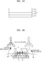
- the first layer may include LFP particles 13. It is noted that FIG. 2E illustrates only the LFP particles 13 in the first layer of the separator on the cathode 10, for convenience, while other elements of the separator are omitted for clarity.
- the separator intensively receives or provides lithium ions Li + from a cathode 10, which includes a cathode plate 11 and a cathode active material 12, at the end of discharging and in the beginning of charging of a battery.
- a cathode 10 which includes a cathode plate 11 and a cathode active material 12
- the concentration of currents may be minimized, and thus a rapid increase in temperature and heat output may be delayed.
- reaction sites may decrease due to an interface formed between the first layer and the substrate, and thus electrolyte side reactions and the resulting gas and metal release or the like may decrease.
- the first layer 21 may be disposed on one surface of the substrate 20, and the second layer 22 may be disposed on the other surface of the substrate 20 opposite the one surface on which the first layer 21 is disposed. That is, the first layer 21 may be disposed on one surface of the substrate 20, and the second layer 22 may be disposed on the other surface that faces opposite the one surface of the substrate 20.
- both the first layer 21 and the second layer 22 may be disposed on one surface and the other surface opposite the one surface of the substrate 20.
- the first layer 21 may be disposed on one surface of the substrate 20, where the second layer 22 may be disposed on the first layer 21, and the first layer 21 may be disposed on the other surface of the substrate 20, where the second layer 22 may be disposed on the first layer 21.
- the second layer 22 may be disposed on one surface of the substrate, where the first layer 21 may be disposed on the second layer 22, and the second layer 22 may be disposed on the other surface of the substrate 20, where the first layer 21 may be disposed on the second layer 22.
- the first layer 21 may be disposed on one surface of the substrate 20, where the second layer 22 may be disposed on the first layer 21, and the second layer 22 may be disposed on the other surface of the substrate 20, where the first layer 21 may be disposed on the second layer 22.
- the first layer 21 and the second layer 22 may be disposed on only one surface of the substrate 20. That is, the first layer 21 and the second layer 22 may be only disposed on one surface of the substrate 20, and the first layer 21 and the second layer 22 may not be disposed on the other surface of the substrate 20.
- the first layer 21 may be disposed on one surface of the substrate 20, and the second layer 22 may be disposed on the first layer 21.
- the second layer 22 may be disposed on one surface of the substrate 20, and the first layer 21 may be disposed on the second layer 22.
- a porosity between the LFP particles 13 in the first layer 21 may be in a range of 30% to 80%, e.g., 30% to 50%.
- a size of a pathway through which lithium ion Li + is about to pass is too small, e.g., spaces between the LPF particles 13 are too small, thereby decrease of physical resistance due to introduction of the first layer 21 with the LFP particles 13 may not be achieved.
- the first layer 21 may further include a first binder.
- the first binder may be a substrate adhesion binder.
- the LFP particles 13 and the first binder in the first layer 21 may be mixed at a weight ratio in a range of 2:8 to 8:2.
- the first binder may be located in the pores between the LFP particles 13. When the first binder is located in the pores as described above, a certain level of permeability may be secured while minimizing a thickness of the first layer 21 formed on the separator 4.
- the first binder may be at least one of carboxyl methyl cellulose (CMC), polyvinylidene fluoride-co-hexafluoropropylene, polyvinylidene fluoride-co-trichloroethylene, polymethylmethacrylate, polybutylacrylate, polyacrylonitrile, polyvinylpyrrolidone, polyvinylacetate, polyvinyl alcohol, polyethylene-co-vinyl acetate, polyethylene oxide, polyarylate, celluloseacetate, cellulose acetate butyrate, cellulose acetate propionate, cyanoethylpullulan, cyanoethylpolyvinylalcohol, cyanoethylcellulose, cyanoethylsucrose, and pullulan.
- CMC carboxyl methyl cellulose
- polyvinylidene fluoride-co-hexafluoropropylene polyvinylidene fluoride-co-trichloroethylene
- the second layer 22 in the separator 4 may include organic particles having a melting point (T m ) in a range of 100 °C to 130 °C.
- T m melting point
- the organic particles melt and block pores of the separator 4 due to sudden heat release and change in external environment, thereby degrading the output and performance of the battery.
- the melting point of the organic particles is higher than 130 °C, melt down of the separator 4 may occur, and thus a shutdown effect caused by the organic particles may not be exhibited. Therefore, the organic particles may melt at a temperature similar to a melting point of the substrate 20 of the separator 4.
- the organic particles are included in the second layer 22 at an amount of 10 % by weight (wt%) or greater based on the total weight of the second layer 22, e.g., the organic particles may be included in the second layer 22 at an amount in a range of 10 wt% to 70 wt% based on the total weight of the second layer 22.
- the amount of the organic particles is lower than 10 wt%, a shutdown effect caused by the organic particles may not be exhibited.
- the amount of the organic particles is higher than 70 wt%, poor coating of the organic particles on the substrate 20 of the separator 4 band particle pushing due to separator winding pressure may occur.
- the organic particles may include at least one of polypropylene (PP), polyethylene (PE), polystyrene (PS), polyvinylidene fluoride (PVDF), polymethylmethacrylate (PMMA), an acrylate-based compound, polyacrylonitrile (PAN), and an azodicarbonamide-based compound.
- the organic particles may include at least one of particle-type particles, plate-type particles, flake-type particles, and a mixture thereof.
- the second layer 22 may further include at least one of a second binder and an inorganic material.
- the second layer 22 may further include only the second binder.
- the second layer 22 may further include only the inorganic material.
- the second layer 22 may further include the second binder and the inorganic material.
- the second layer 22 may further include the second binder.
- the second binder may be a high heat-resistant binder.
- the second binder may be at least one of a sulfonate-based compound or a derivative thereof, an acrylamide-based compound or a derivative thereof, an acrylonitrile-based compound or a derivative thereof, a copolymer thereof, and a mixture thereof.
- the copolymer may refer to a copolymer of at least any two of the above compounds", "the mixture may refer to a mixture of at least any two of the above compounds.
- the organic particles and the inorganic material in the second layer 22 may be mixed at a weight ratio in a range of 2:8 to 8:2.
- the inorganic material may be inorganic particles having at least two different particle diameters or may be inorganic particles of one type.
- the inorganic material may be a mixture of inorganic particles having at least two different particle diameters. That is, when the second layer 22 of the separator 4 includes inorganic particles having at least two different particle diameters, i.e., bimodal inorganic particles, inorganic particles having a small particle diameter may fill pores between inorganic particles having a large particle diameter, thereby efficiently performing a shutdown function of the separator 4 at high temperatures due to the inorganic particles. In this regard, life characteristics of the lithium battery may improve as well as thermal stability of the lithium battery.
- a thickness of the first layer 21 may be in a range of 0.1 ⁇ m to 5.0 ⁇ m. In another embodiment, a thickness of the second layer 22 may be in a range of 0.1 ⁇ m to 5.0 ⁇ m.
- the first layer 21 and the second layer 22 in the separator 4 may be formed in a thin layer.
- thicknesses of the first layer 21 and the second layer 22 may each independently be in a range of 0.5 ⁇ m to 5.0 ⁇ m, e.g., 0.5 ⁇ m to 4.0 ⁇ m, 1.0 ⁇ m to 4.0 ⁇ m, 2.0 ⁇ m to 4.0 ⁇ m, 2.0 ⁇ m to 3.5 ⁇ m, 3.0 ⁇ m to 5.0 ⁇ m.
- the separator 4 including the first layer 21 and the second layer 22 may provide improved adhesion and permeability.
- a thickness of an electrode assembly may be minimized, thereby maximizing capacity per volume of the battery.
- the separator 4 may further include an electrode adhesion layer 23 disposed on at least one layer of the first layer 21 and the second layer 22.
- the first layer 21 may be between the substrate 20 and the electrode adhesion layer 23.
- the electrode adhesion layer 23 may include a water-based binder existing in the form of particles after coating and drying and having a glass transition temperature (T g ) of about 50 °C or higher.
- the water-based binder may include an acrylate group or a styrene group.
- a thickness of the electrode adhesion layer 23 may be in a range of 0.3 ⁇ m to 0.5 ⁇ m.
- the substrate 20 may be a porous substrate.
- the porous substrate may be a porous layer including polyolefin.
- Polyolefin has an excellent short-circuit preventing effect and may improve battery stability by a shutdown effect.
- the porous substrate may be a layer that is formed of polyolefin, e.g., polyethylene, polypropylene, polybutene, or polyvinyl chloride, or a mixture or a copolymer thereof.
- Other examples of the porous layer may include a polyolefin-based resin, a porous layer prepared by weaving polyolefin-based fibers, a non-woven fabric including polyolefin, and an aggregate of insulating material particles.
- the porous layer including polyolefin may include a binder solution having excellent coating property for preparing a coating layer on the substrate and may increase a capacity per unit volume by increasing an active material ratio in the battery by making a layer thickness of the separator thinner.
- polyolefin used as a material of a porous substrate may be a homopolymer, e.g., polyethylene, polypropylene, or a copolymer or a mixture thereof.
- Polyethylene may be lowdensity, medium-density, or high-density polyethylene, and high-density polyethylene may be used as polyethylene in terms of mechanical strength.
- polyethylene may be prepared by mixing at least two different types of polyethylene to impart flexibility. Examples of a polymer catalyst used in preparation of polyethylene may include a Ziegler-Natta catalyst, a Phillips catalyst, or a metallocene catalyst.
- a weight average molecular weight of polyethylene may be in a range of about 100,000 to about 12,000,000, e.g., about 200,000 to about 3,000,000.
- Polypropylene may be, e.g., a homopolymer, a random copolymer, or a block copolymer, which may be used alone or may be used as a mixture of at least two selected therefrom.
- the polymer catalyst may include a Ziegler-Natta catalyst or a metallocene catalyst.
- tacticity may include isotactic, syndiotactic, or atactic, and inexpensive isotactic polypropylene may be used.
- an additive e.g., polyolefin and an anti-oxidant in addition to polyethylene or polypropylene, may be added to polyolefin.
- a porous substrate may include polyolefin, e.g., polyethylene or polypropylene.
- a multilayer having at least two layers may be used in the porous substrate, wherein the multilayer may be a mixed multilayer, e.g., a separator having a two layers of polyethylene and polypropylene, a separator having a three layers of polyethylene, polypropylene, and polyethylene, or a separator having a three layers of polypropylene, polyethylene, and polypropylene, but examples of the mixed multilayer are not limited thereto, and any material or composition available as a porous substrate in the art may be used.
- the porous substrate may include a diene-based polymer prepared by polymerizing a monomer composition including a diene-based monomer.
- the diene-based monomer may be a conjugated diene-based monomer or a non-conjugated diene-based monomer.
- Examples of the diene-based monomer may include at least one of the group consisting of 1,3-butadiene, isoprene, 2-chloro-1,3-butadiene, 2,3-dimethyl-1,3-butadiene, 2-ethyl-1,3-butadiene, 1,3-pentadiene, chloroprene, vinylpyridine, vinylnorbornene, dicyclopentadiene, and 1,4-hexadiene, but the examples are not limited thereto, and any material available as a diene-based monomer in the art may be used.
- a thickness of the porous substrate in the separator 4 may be in a range of about 1 ⁇ m to about 100 ⁇ m,e.g., about 1 ⁇ m to about 30 ⁇ m,about 3 ⁇ m to about 20 ⁇ m about 3 ⁇ m to about 15 ⁇ m,or about 3 ⁇ m to about 12 ⁇ m.
- a thickness of the porous substrate is less than about 1 ⁇ m,mechanical properties of the separator 4 may not be maintained.
- a thickness of the porous substrate is greater than about 100 ⁇ m,an internal resistance of the lithium battery may increase.
- a porosity of the porous substrate in the separator 4 may be in a range of about 5 % to about 95 %. When the porosity is less than about 5 %, an internal resistance of the lithium battery may increase. When the porosity is greater than about 95 %, mechanical properties of the porous substrate may not be maintained.
- a pore diameter of the porous substrate in the separator 4 may be in a range of about 0.01 ⁇ m to about 50 ⁇ m,e.g., about 0.01 ⁇ m to about 20 ⁇ m or about 0.01 ⁇ m to about 10 ⁇ m.
- the pore diameter of the porous substrate is less than about 0.01 ⁇ m,an internal resistance of the lithium battery may increase.
- the pore diameter of the porous substrate is greater than about 50 ⁇ m,mechanical properties of the porous substrate may not be maintained.
- the first layer 21 or the second layer 22 may further include inorganic filler particles.
- the inorganic filler particles may be a metal oxide, a metalloid oxide, or a combination thereof.
- the inorganic filler particles may be at least one of alumina (Al 2 O 3 ), boehmite, BaSO 4 , MgO, Mg(OH) 2 , clay, silica (SiO 2 ), and TiO 2 .
- the alumina or silica has small particle diameters and thus may be useful in preparing a dispersion.
- the inorganic filler particles may be Al 2 O 3 , SiO 2 , TiO 2 , SnO 2 , CeO 2 , NiO, CaO, ZnO, MgO, ZrO 2 , Y 2 O 3 , SrTiO 3 , BaTiO 3 , MgF2, Mg(OH)2, or a combination thereof.
- the inorganic filler particles may be, e.g., in a sphere shape, a plate shape, or a fiber shape.
- the inorganic filler particles having a plate shape may be, e.g., alumina or boehmite. In this case, shrinkage of a surface area of the separator 4 at high temperatures may be further suppressed, a relatively high porosity may be secured, and characteristics of the lithium battery during a penetration test may improve.
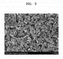
- an aspect ratio of the inorganic filler particles may be in a range of about 1:5 to about 1:100, e.g., about 1:10 to about 1:100, about 1:5 to about 1:50, or about 1:10 to about 1:50.
- a length ratio of the longest axis to the shortest axis may be in a range of about 1 to about 3, e.g., about 1 to about 2 or about 1.
- the aspect ratio and the length ratio of the longest axis to the shortest axis may be measured through a scanning electron microscope (SEM), e.g., FIG. 3 .
- SEM scanning electron microscope
- an average angle of a flat surface of the inorganic filler particles to one surface of the porous substrate may be in a range of about 0 degree to about 30 degrees, e.g., about 0 degree. That is, the one surface of the porous substrate and the flat surface of the inorganic filler particles may be parallel to each other.
- the average angle of a flat surface of the inorganic filler particles to one surface of the porous substrate is within this range above, thermal shrinkage of the porous substrate may be efficiently prevented, and thus a separator having a reduced shrinkage may be provided.
- any convenient method of preparing the separator 4 may be used. For example, a slurry including the LFP particles 13, a first binder, the organic particles, a second binder, and an inorganic material may be prepared, the slurry may be applied on the substrate 20, and the substrate 20 may be dried and roll-pressed to prepare the separator 4.
- the slurry may be applied by printing, compressing, press-fitting, roller coating, blade coating, brush coating, dip coating, spray coating, or lubrication coating.
- a lithium battery may include the cathode 10, an anode, and the separator 4 disposed between the cathode 10 and the anode.
- the lithium battery includes the separator 4 described above, thermal stability, especially penetrating and breakdown voltage (BDV) characteristics may improve, and short-circuits between electrodes at high temperatures may be suppressed.
- BDV breakdown voltage
- adhesion between the electrode (the cathode or the anode) and the separator increases, and thus volume change during charging/discharging of the lithium battery may be suppressed.
- deterioration of the lithium battery accompanied by the volume change of the lithium battery may be suppressed, and thus stability and life characteristics of the lithium battery may improve.
- a 3-point bending strength of the lithium battery may be at least about 150 N.
- a 3-point bending strength of the lithium battery may be in a range of about 150 N to about 200 N.
- the lithium battery may be prepared as follows. First, an anode active material, a conducting agent, a binder, and a solvent are mixed to prepare an anode active material composition.
- the anode active material composition may be directly coated and dried on a metallic current collector to prepare an anode plate.
- the anode active material composition may be cast on a separate support to form an anode active material film, which may then be separated from the support and laminated on a metallic current collector to prepare an anode plate.
- a type of the anode is not limited thereto and may be different from the type described above.
- the anode active material may be a non-carbonaceous material.
- the anode active material may include at least one of a metal alloyable with lithium, an alloy of a metal that is alloyable with lithium, and an oxide of a metal alloyable with lithium.
- Examples of the metal alloyable with lithium may be Si, Sn, Al, Ge, Pb, Bi, Sb, a Si-Y' alloy (where Y' is an alkali metal, an alkali earth metal, Group XIII to XIV elements, a transition metal, a rare earth element, or a combination thereof, and Y' is not Si), and a Sn-Y' alloy (where Y' is an alkali metal, an alkali earth metal, Group XIII to XIV elements, a transition metal, a rare earth element, or a combination thereof, and Y' is not Sn).
- Y' may be magnesium (Mg), calcium (Ca), strontium (Sr), barium (Ba), radium (Ra), scandium (Sc), yttrium (Y), titanium (Ti), zirconium (Zr), Hf, Rf, V, Nb, Ta, Db, chromium (Cr), molybdenum (Mo), tungsten (W), seaborgium (Sg), technetium (Tc), Rhenium (Re), Bohrium (Bh), iron (Fe), lead (Pb), ruthenium (Ru), osmium (Os), hassium (Hs), rhodium (Rh), iridium (Ir), palladium (Pd), platinum (Pt), copper (Cu), silver (Ag), gold (Au), zinc (Zn), cadmium (Cd), boron (B), aluminum (Al), gallium (Ga), tin (Sn), indium (In), germanium (G
- transition metal oxide may include a lithium titanium oxide, a vanadium oxide, and a lithium vanadium oxide.
- non-transition metal oxide may include SnO 2 and SiO x (where 0 ⁇ x ⁇ 2).
- the anode active material may be at least one of Si, Sn, Pb, Ge, Al, SiO x (where 0 ⁇ x ⁇ 2), SnO y (where 0 ⁇ y ⁇ 52), Li 4 Ti 5 O 12 , TiO 2 , LiTiO 3 , and Li 2 Ti 3 O 7 , but the anode active material is not limited thereto, and any material available as a non-carbonaceous anode active material in the art may be used.
- a composite of the non-carbonaceous anode active material and a carbonaceous material may be used, and a carbonaceous anode active material may be further included in addition to the non-carbonaceous material.
- Examples of the carbonaceous material are crystalline carbon, amorphous carbon, and mixtures thereof.
- Examples of the crystalline carbon are graphite, e.g., natural graphite or artificial graphite that are non-shaped or in plate, flake, spherical, or fibrous form, and examples of the amorphous carbon are soft carbon (carbon sintered at low temperatures), hard carbon, meso-phase pitch carbides, and sintered cokes.
- the conducting agent examples include acetylene black, ketjen black, natural graphite, artificial graphite, carbon black, carbon fiber; metal powder or metal fiber of copper, nickel, aluminum, or silver; and a conductive material, such as a polyphenylene derivative, which may be used alone or as a mixture thereof, but embodiments are not limited thereto, and any material available as a conducting agent in the art may be used. Also, the crystalline carbonaceous material may be added as a conducting agent.
- binder examples include a vinylidene fluoride/hexafluoropropylene copolymer, polyvinylidene fluoride (PVDF), polyacrylonitrile, polymethylmethacrylate, polytetrafluoroethylene, mixtures thereof, and a styrene butadiene rubber polymer, but embodiments are not limited thereto, and any material available as a binder in the art may be used.
- PVDF polyvinylidene fluoride
- solvent examples include N-methyl-pyrrolidone, acetone, and water, but embodiments are not limited thereto, and any material available as a solvent in the art may be used.
- the amounts of the anode active material, the conducting agent, the binder, and the solvent may be in ranges that are commonly used in lithium batteries. At least one of the conducting agent, the binder, and the solvent may be omitted according to the use and the structure of the lithium battery.
- a composition of the binder used in preparation of the anode may be the same with a binder composition included in the first layer and the second layer of the separator.
- a cathode active material, a conducting agent, a binder, and a solvent are mixed to prepare a cathode active material composition.
- the cathode active material composition may be directly coated and dried on a metallic current collector to prepare a cathode plate.
- the cathode active material composition may be cast on a separate support to form a cathode active material film, which may then be separated from the support and laminated on a metallic current collector to prepare a cathode plate.
- the cathode active material may be at least one of a lithium cobalt oxide, a lithium nickel cobalt manganese oxide, a lithium nickel cobalt aluminum oxide, a lithium iron phosphate, and a lithium manganese oxide, but embodiments are not limited thereto, and any material available as a cathode active material in the art may be used.
- the cathode active material may be a compound represented by one of the following formulae: Li a A 1-b B' b D' 2 (where 0.90 ⁇ a ⁇ 1.8, and 0 ⁇ b ⁇ 0.5); Li a E 1-b B' b O 2-c D' c (where 0.90 ⁇ a ⁇ 1.8, 0 ⁇ b ⁇ 0.5, and 0 ⁇ c ⁇ 0.05); LiE 2-b B' b O 4-c D' c , (where 0 ⁇ b ⁇ 0.5, and 0 ⁇ c ⁇ 0.05); Li a Ni 1-b-c Co b B' c D' ⁇ (where 0.90 ⁇ a ⁇ 1.8, 0 ⁇ b ⁇ 0.5, 0 ⁇ c ⁇ 0.05, and 0 ⁇ ⁇ ⁇ 2); Li a Ni 1-b-c Co b B' c O 2- ⁇ F' ⁇ (where 0.90 ⁇ a a ⁇
- A may be selected from nickel (Ni), cobalt (Co), manganese (Mn), and combinations thereof;
- B' may be selected from aluminum (Al), nickel (Ni), cobalt (Co), manganese (Mn), chromium (Cr), iron (Fe), magnesium (Mg), strontium (Sr), vanadium (V), a rare earth element, and combinations thereof;
- D' may be selected from oxygen (O), fluorine (F), sulfur (S), phosphorus (P), and combinations thereof;
- E may be selected from cobalt (Co), manganese (Mn), and combinations thereof;
- F' may be selected from fluorine (F), sulfur (S), phosphorus (P), and combinations thereof;
- G may be selected from aluminum (Al), chromium (Cr), manganese (Mn), iron (Fe), magnesium (Mg), lanthanum (La), cerium (Ce), strontium (Sr), vanadium (V), and combinations thereof;
- Q may
- the compounds listed above as cathode active materials may have a surface coating layer (hereinafter, also referred to as "coating layer").
- a surface coating layer hereinafter, also referred to as "coating layer”
- the coating layer may include a coating element compound selected from oxide, hydroxide, oxyhydroxide, oxycarbonate, and hydroxycarbonate of the coating element.
- the compounds for the coating layer may be amorphous or crystalline.
- the coating element for the coating layer may be magnesium (Mg), aluminum (Al), cobalt (Co), potassium (K), sodium (Na), calcium (Ca), silicon (Si), titanium (Ti), vanadium (V), tin (Sn), germanium (Ge), gallium (Ga), boron (B), arsenic (As), zirconium (Zr), or a mixture thereof.
- the coating layer may be formed using any method that does not adversely affect the physical properties of the cathode active material when a compound of the coating element is used.
- the coating layer may be formed using a spray coating method or a dipping method. The coating methods may be well understood by one of ordinary skill in the art, and thus a detailed description thereof will be omitted.
- the cathode active material may be LiNiO 2 , LiCoO 2 , LiMn x O 2x (where x is 1 or2), LiNi 1-x Mn x O 2 (where 0 ⁇ x ⁇ 1), LiNi 1-x-y Co x Mn y O 2 (where 0 ⁇ x ⁇ 0.5, and 0 ⁇ y ⁇ 0.5), LiFeO 2 , V 2 O 5 , TiS, or MoS.
- the conducting agent, the binder, and the solvent used for the cathode active material composition may be the same as those used for the anode active material composition.
- a plasticizer may be further added to the cathode active material composition and/or to the anode active material composition to form pores in a corresponding electrode plate.
- the amounts of the cathode active material, the conducting agent, the binder, and the solvent may be in ranges that are commonly used in lithium batteries. At least one of the conducting agent, the binder, and the solvent may be omitted according to the use and the structure of the lithium battery.
- a composition of the binder used in preparation of the cathode may be the same with a binder composition included in the first layer 21 and the second layer 22 of the separator 4.
- the separator 4 may be disposed between the cathode 10 and the anode.
- the separator 4 disposed between the cathode 10 and the anode may include the first layer 21 and the second layer 22 disposed on one surface of the substrate 20 as described above.
- the first layer 21 may include LiFePO 4 (LFP) particles
- the second layer 22 may include organic particles having a melting point (T m ) in a range of about 100 °C to about 130 °C.
- the separator 4 may be separately prepared and then disposed between the cathode 10 and the anode.
- the separator 4 may be prepared by rolling an electrode assembly including the cathode 10, the separator 4, and an anode wound in the form of a jelly-roll, accommodating the jelly-roll in a battery case or pouch, pre-charging the jelly-roll accommodated in the battery case or pouch while thermally softening the jelly-roll under pressure, heat-pressing the charged jelly-roll, cold-pressing the charged jelly-roll, and then performing a formation process that charges/discharges the charged jelly-roll under pressure and heat. Further details of the preparation method of a composite separator may be referred to the following description of the method of preparing a separator.
- an electrolyte is prepared.
- the electrolyte may be in the state of liquid or gel.
- the electrolyte may be an organic electrolyte solution.
- the electrolyte may be in a solid phase. Examples of the electrolyte are boron oxide and lithium oxynitride, but embodiments are not limited thereto, and any material available as a solid electrolyte in the art may be used.
- the solid electrolyte may be formed on the anode by, e.g., sputtering.
- the organic electrolyte solution may be prepared.
- the organic electrolyte solution may be prepared by dissolving a lithium salt in an organic solvent.
- the organic solvent may be any solvent available as an organic solvent in the art.
- the organic solvent may be propylene carbonate, ethylene carbonate, fluoroethylene carbonate, butylene carbonate, dimethyl carbonate, diethyl carbonate, methylethyl carbonate, methylpropyl carbonate, ethylpropyl carbonate, methylisopropyl carbonate, dipropyl carbonate, dibutyl carbonate, benzonitrile, acetonitrile, tetrahydrofuran, 2-methyltetrahydrofuran, ⁇ -butyrolactone, dioxolane, 4-methyldioxolane, N,N-dimethyl formamide, dimethyl acetamide, dimethylsulfoxide, dioxane, 1,2-dimethoxyethane, sulfolane, dichloroethane, chlorobenzene, nitrobenzene, diethylene glycol, dimethyl ether, or a mixture thereof.
- the lithium salt may be any material available as a lithium salt in the art.
- the lithium salt may be LiPF 6 , LiBF 4 , LiSbF 6 , LiAsF 6 , LiClO 4 , LiCF 3 SO 3 , Li(CF 3 SO) 2 N, LiC 4 F 9 SO 3 , LiAlO 2 , LiAlCl 4 , LiN(C x F 2x+1 SO 2 )(C y F 2y+1 SO 2 ) (where x and y are each independently a natural number), LiCI, Lil, or a mixture thereof.
- a lithium battery 1 may include the cathode 3, an anode 2, and the separator 4.
- the cathode 3, the anode 2, and the separator 4 may be wound or folded, and then sealed in a battery case 5.
- the battery case 5 may be filled with an organic electrolytic solution and sealed with a cap assembly 6, thereby completing the manufacture of the lithium battery 1.
- the battery case 5 may be, e.g., a cylindrical type, a rectangular type, or a thin-film type.
- the lithium battery 1 may be a thin-film type battery.
- the lithium battery 1 may be a lithium ion battery.
- the lithium battery 1 may be a lithium ion polymer battery.
- the separator 4 may be disposed between the cathode 3 and the anode 2 to form a battery assembly.
- the battery assembly may be stacked in a bi-cell structure or may be rolled in the form of a jelly-roll and then impregnated with an electrolytic solution.
- the resultant battery assembly may be put into a pouch and hermetically sealed, thereby completing the manufacture of a lithium ion polymer battery.
- a plurality of battery assemblies may be stacked to form a battery pack.
- the battery pack may be used in any device that requires high capacity and high output, e.g., in a laptop computer, a smart phone, or an electric vehicle.
- the lithium battery may have improved high rate characteristics and lifetime characteristics.
- lithium battery may be used in an electric vehicle (EV), e.g., a hybrid vehicle such as a plug-in hybrid electric vehicle (PHEV).
- EV electric vehicle
- PHEV plug-in hybrid electric vehicle
- LiFePO 4 particles LPF particles 13
- CMC first binder
- polyethylene (PE) having an average particle diameter (D50) of about 0.2 ⁇ m was prepared. 11 parts by weight of the organic particles, 4 parts by weight of a binder (high heat-resistant acryl-based compound), and 85 parts by weight of inorganic particles (boehmite) were mixed to prepare a slurry for forming the second layer 22.
- the slurry for the first layer 21 was applied by gravure printing to a surface of a polyethylene porous substrate (i.e., the substrate 20) having a thickness of about 8.7 ⁇ m to form the first layer 21 having a thickness of about 3.0 ⁇ m on the surface of the porous substrate, and the slurry for the second layer 22 was applied by gravure printing to the other surface of the polyethylene porous substrate to form the second layer 22 having a thickness of about 3.0 ⁇ m on the surface of the porous substrate, thereby completing the preparation of the separator 4 having the first layer 21 and the second layer 22 on opposite surfaces of the substrate 20.
- a thickness of the separator 4 was about 14.7 ⁇ m.
- a separator was prepared in the same manner as in Preparation Example 1, except that the first layer and the second layer were not formed. That is, the comparative separator of Comparative Preparation example 1 included only the porous substrate as a separator.
- a separator was prepared in the same manner as in Preparation Example 1, except that the second layer was not formed. That is, the comparative separator of Comparative Preparation example 2 included only the porous substrate with a first layer.
- a separator was prepared in the same manner as in Preparation Example 1, except that 5 parts by weight of the organic particles, 4 parts by weight of the binder, and 91 parts by weight of the inorganic particles were mixed to prepare a slurry for forming a second layer.
- a separator was prepared in the same manner as in Comparative Preparation Example 3, except that the first layer was not formed.
- a separator was prepared in the same manner as in Preparation Example 1, except that the first layer was not formed. That is, the comparative separator of Comparative Preparation example 5 included only the porous substrate with a second layer.
- C1SR graphite particles
- SBR styrene-butadiene-rubber
- CMC carboxymethylcellulose
- the slurry was coated on a copper current collector having a thickness of 10 ⁇ m by using a doctor blade, dried in a hot-air dryer at 100 °C for 0.5 hours, and then dried again in a vacuum at 120 °C for 4 hours, and the resultant was roll-pressed to prepare an anode plate.
- 97 wt% of LiCoO 2 , 1.5 wt% of carbon black powder as a conducting agent, and 1.5 wt % of polyvinylidenefluoride (PVDF, available from SOLVAY) were mixed, and then the mixture was added to N-methyl-2-pyrrolidone as a solvent and stirred by using a mechanical stirrer for 30 minutes to prepare a cathode active material slurry.
- the slurry was coated on an aluminum current collector having a thickness of 20 ⁇ m by using a doctor blade, dried in a hot-air dryer at 100 °C for 0.5 hours, and then dried again in a vacuum at 120 °C for 4 hours, and the resultant was roll-pressed to prepare a cathode plate.
- the separator prepared in Preparation Example 1 was arranged between the cathode and anode plates prepared as above, and then the resulting structure was wound to prepare an electrode assembly in the form of a jelly-roll.
- the jelly-roll was accommodated in a pouch and an electrolytic solution was injected thereinto, and then the pouch was hermetically sealed.
- electrolytic solution a solution prepared by dissolving 1.3 M LiPF 6 in a mixed solvent of ethylene carbonate (EC)/methyl ethyl carbonate (EMC)/diethyl carbonate (DEC) in a volume ratio of 3:5:2 was used.
- EC ethylene carbonate
- EMC methyl ethyl carbonate
- DEC diethyl carbonate
- the jelly-roll accommodated in the pouch was subjected to thermal softening at a temperature of 70 °C for 1 hour while a pressure of 250 kgf/cm 2 was applied thereto and to pre-charging up to a state of charging (SOC) of 50 %.
- SOC state of charging
- the jelly-roll was heat-pressed at a temperature of 85 °C for 180 seconds while a pressure of 200 kgf/cm 2 was applied thereto.
- a phase of the binder was changed from a gel state to a sol state, adhesion between the separator and the cathode/anode was generated.
- the jelly-roll was cold-pressed at a temperature of 22 °C to 23 °C for 90 seconds while a pressure of 200 kgf/cm 2 was applied thereto.
- a phase of the binder was changed from a sol state to a gel state.
- the pouch was degassed, and the lithium battery was charged at a constant current rate of 0.2 C at 45 °C for 1 hour while a pressure of 200 kgf/cm 2 was applied to the jelly-roll until the voltage reached 4.3 V, and charged at a constant voltage of 4.3 V until the current reached 0.05 C. Thereafter, cycles of discharging at a constant current of 0.2 C until the voltage reached 3.0 V were repeated five times, thereby performing a formation process.
- Lithium batteries were prepared in the same manner as in Example 1, except that the separators prepared in Comparative Preparation Examples 1 to 5 were used, each respectively.
- the jelly-roll was taken out of the pouch of each of the lithium batteries of Example 1 and Comparative Examples 1 to 5 having undergone the formation process, and the separator was separated from each assembly to evaluate penetration characteristics.
- the results are shown in Table 1 below. After performing a nail penetration test on each of the separators, a degree and a probability of abnormality occurrence were evaluated according to the observed phenomenon. When the result was L4-3 and L6, the separator was evaluated as having abnormality.
- the separator prepared in Example 1 exhibited significantly enhanced penetrating characteristics as compared to those of the separators prepared in Comparative Examples 1 to 5. That is, as described above, according to one or more embodiments, when a separator in a lithium battery includes the structure of Example 1, the separator may have improved penetration stability and enhanced adhesion to an electrode plate, and thus life characteristics and battery stability of the lithium battery may improve.
- olefin-based polymers are widely used in the fabrication of separators for lithium batteries.
- Olefin-based polymers have excellent flexibility but have low strength when impregnated with an electrolytic solution, and short-circuiting may occur in batteries due to rapid thermal contraction at high temperatures of 100 °C or higher.
- a separator that overcomes existing problems and has excellent penetration characteristics and thermal stability is provided. That is, embodiments provide a separator having an improved thermal stability and a lithium battery including the separator.
- Example embodiments have been disclosed herein, and although specific terms are employed, they are used and are to be interpreted in a generic and descriptive sense only and not for purpose of limitation. In some instances, as would be apparent to one of ordinary skill in the art as of the filing of the present application, features, characteristics, and/or elements described in connection with a particular embodiment may be used singly or in combination with features, characteristics, and/or elements described in connection with other embodiments unless otherwise specifically indicated.
Landscapes
- Chemical & Material Sciences (AREA)
- Chemical Kinetics & Catalysis (AREA)
- Electrochemistry (AREA)
- General Chemical & Material Sciences (AREA)
- Engineering & Computer Science (AREA)
- Inorganic Chemistry (AREA)
- Manufacturing & Machinery (AREA)
- Materials Engineering (AREA)
- Composite Materials (AREA)
- Ceramic Engineering (AREA)
- Cell Separators (AREA)
- Secondary Cells (AREA)
Claims (13)
- Separator (4), umfassend:ein Substrat (20);eine erste Schicht (21), die LiFePO4-(LFP-)-Partikel beinhaltet; undeine zweite Schicht (22), die organische Teilchen mit einem Schmelzpunkt in einem Bereich von 100 °C bis 130 °C beinhaltet und in der zweiten Schicht (22) in einer Menge von mindestens 10 Gew.-%, bezogen auf das Gesamtgewicht der zweiten Schicht (22), beinhaltet ist, wobei die erste Schicht (21) und die zweite Schicht (22) auf gegenüberliegenden Oberflächen des Substrats (20) angeordnet sind.
- Separator nach Anspruch 1, wobei die Porosität zwischen den LFP-Partikeln in der ersten Schicht (21) in einem Bereich von 30 % bis 80 % liegt.
- Separator nach Anspruch 1, wobei die erste Schicht (21) ferner ein erstes Bindemittel beinhaltet, wobei die LFP-Partikel und das erste Bindemittel in der ersten Schicht (21) in einem Gewichtsverhältnis im Bereich von 2:8 bis 8:2 gemischt sind.
- Separator nach Anspruch 3, wobei das erste Bindemittel mindestens eines der folgenden ist: Carboxymethylcellulose (CMC), Polyvinylidenfluorid-cohexafluorpropylen, Polyvinylidenfluorid-cotrichlorethylen, Polymethylmethacrylat, Polybutylacrylat, Polyacrylnitril, Polyvinylpyrrolidon, Polyvinylacetat, Polyvinylalkohol, Polyethylen-co-vinylacetat, Polyethylenoxid, Polyarylat, Celluloseacetat, Celluloseacetatbutyrat, Celluloseacetatpropionat, Cyanoethylpullulan, Cyanoethylpolyvinylalkohol, Cyanoethylcellulose, Cyanoethylsucrose und Pullulan.
- Separator nach Anspruch 1, wobei die organischen Partikel mindestens eines von Polypropylen (PP), Polyethylen (PE), Polystyrol (PS), Polyvinylidenfluorid (PVDF), Polymethylmethacrylat (PMMA), eine Verbindung auf Acrylatbasis, Polyacrylnitril (PAN) und eine Verbindung auf Azodicarbonamidbasis beinhalten.
- Separator nach Anspruch 1, wobei die organischen Partikel partikelartige Partikel, plättchenartige Partikel, schuppenartige Partikel oder eine Mischung davon beinhalten.
- Separator nach Anspruch 1, wobei die zweite Schicht (22) ferner mindestens eines von einem zweiten Bindemittel und einem anorganischen Material beinhaltet, wobei die zweite Schicht (22) ferner das anorganische Material beinhaltet und die organischen Partikel und das anorganische Material in einem Gewichtsverhältnis im Bereich von 2:8 bis 8:2 gemischt sind.
- Separator nach Anspruch 7, wobei die zweite Schicht (22) ferner das zweite Bindemittel beinhaltet, wobei das zweite Bindemittel mindestens eine Verbindung auf Sulfonatbasis oder ein Derivat davon, eine Verbindung auf Acrylamidbasis oder ein Derivat davon, eine Verbindung auf Acrylnitrilbasis oder ein Derivat davon, ein Copolymer davon oder eine Mischung davon ist.
- Separator nach Anspruch 7 oder 8, wobei die zweite Schicht (22) ferner das anorganische Material beinhaltet und das anorganische Material entweder anorganische Partikel von mindestens zwei Arten mit unterschiedlichen Partikeldurchmessern oder anorganische Partikel einer Art beinhaltet.
- Separator nach Anspruch 1, wobei die Dicke der ersten Schicht (21) in einem Bereich von 0,1 µm bis 5,0 µm liegt; und/oder die Dicke der zweiten Schicht (22) in einem Bereich von 0,1 µm bis 5,0 µm liegt.
- Separator nach Anspruch 1, ferner umfassend eine Elektrodenhaftschicht (23) auf mindestens einer der ersten Schicht (21) und der zweiten Schicht (22).
- Separator nach Anspruch 11, wobei die Dicke der Elektrodenhaftschicht (23) in einem Bereich von 0,3 µm bis 0,5 µm liegt.
- Lithium-Batterie (1), umfassend:eine Kathode (3); eine Anode (2); undSeparator (4) nach Anspruch 1, wobei der Separator (4) zwischen der Kathode (3) und der Anode (2) angeordnet ist.
Applications Claiming Priority (1)
| Application Number | Priority Date | Filing Date | Title |
|---|---|---|---|
| KR1020190018825A KR102331720B1 (ko) | 2019-02-18 | 2019-02-18 | 분리막 및 이를 채용한 리튬전지 |
Publications (2)
| Publication Number | Publication Date |
|---|---|
| EP3696880A1 EP3696880A1 (de) | 2020-08-19 |
| EP3696880B1 true EP3696880B1 (de) | 2022-09-28 |
Family
ID=69581982
Family Applications (1)
| Application Number | Title | Priority Date | Filing Date |
|---|---|---|---|
| EP20157052.0A Active EP3696880B1 (de) | 2019-02-18 | 2020-02-13 | Separator und lithiumbatterie damit |
Country Status (5)
| Country | Link |
|---|---|
| US (1) | US11527801B2 (de) |
| EP (1) | EP3696880B1 (de) |
| JP (1) | JP7001723B2 (de) |
| KR (1) | KR102331720B1 (de) |
| CN (1) | CN111584806B (de) |
Families Citing this family (11)
| Publication number | Priority date | Publication date | Assignee | Title |
|---|---|---|---|---|
| KR102629464B1 (ko) | 2020-04-13 | 2024-01-25 | 삼성에스디아이 주식회사 | 세퍼레이터 및 이를 채용한 리튬 전지 |
| CN111653712B (zh) * | 2020-05-21 | 2021-09-28 | 上海恩捷新材料科技有限公司 | 一种电化学装置隔离膜及其制备方法 |
| JP7597416B2 (ja) * | 2020-09-14 | 2024-12-10 | ビーアイエー パワー エルエルシー | 高エネルギおよび高電力要件用の電気化学エネルギ貯蔵システム |
| KR102924314B1 (ko) * | 2021-03-26 | 2026-02-05 | 삼성에스디아이 주식회사 | 세퍼레이터 및 이를 채용한 리튬 전지 |
| CN115799656B (zh) * | 2021-09-10 | 2023-12-15 | 宁德时代新能源科技股份有限公司 | 电极组件及与其相关的电池单体、电池、装置和制造方法 |
| DE102021212431B3 (de) | 2021-11-04 | 2023-03-16 | Volkswagen Aktiengesellschaft | Separatorlage und Elektrodenanordnung für eine Batteriezelle |
| CN117083741A (zh) * | 2022-01-17 | 2023-11-17 | 宁德时代新能源科技股份有限公司 | 隔膜及其相关的二次电池、电池模块、电池包和用电装置 |
| JP7626122B2 (ja) | 2022-11-04 | 2025-02-04 | トヨタ自動車株式会社 | 電極、電池および電極の製造方法 |
| JP7626112B2 (ja) | 2022-09-01 | 2025-02-04 | トヨタ自動車株式会社 | 電極、電池および電極の製造方法 |
| JP2024057772A (ja) | 2022-10-13 | 2024-04-25 | トヨタ自動車株式会社 | 電極体および電池 |
| KR102875711B1 (ko) * | 2023-03-09 | 2025-10-22 | 인천대학교 산학협력단 | 질화붕소를 포함하는 리튬 이차전지용 분리막, 이의 제조방법 및 이를 포함하는 리튬 이차전지 |
Family Cites Families (28)
| Publication number | Priority date | Publication date | Assignee | Title |
|---|---|---|---|---|
| KR100983438B1 (ko) * | 2007-05-15 | 2010-09-20 | 주식회사 엘지화학 | 다공성 코팅층이 형성된 세퍼레이터 및 이를 구비한전기화학소자 |
| KR100947181B1 (ko) | 2007-11-19 | 2010-03-15 | 주식회사 엘지화학 | 다공성 코팅층이 형성된 세퍼레이터 및 이를 구비한전기화학소자 |
| WO2010008003A1 (ja) * | 2008-07-16 | 2010-01-21 | 東レ株式会社 | 蓄電デバイス用セパレータ |
| JP5621248B2 (ja) * | 2009-02-03 | 2014-11-12 | ソニー株式会社 | セパレータおよび電池 |
| US20120015246A1 (en) | 2010-05-27 | 2012-01-19 | Arkema Inc. | Waterborne fluoropolymer composition |
| WO2010138647A1 (en) | 2009-05-29 | 2010-12-02 | Arkema Inc. | Aqueous polyvinylidene fluoride composition |
| KR101055431B1 (ko) * | 2009-11-23 | 2011-08-08 | 주식회사 엘지화학 | 다공성 코팅층을 구비한 분리막의 제조방법, 이로부터 형성된 분리막 및 이를 구비한 전기화학소자 |
| FR2956776B1 (fr) * | 2010-02-25 | 2012-03-23 | Commissariat Energie Atomique | Accumulateur lithium-ion presentant une forte puissance et un faible cout |
| US10158110B2 (en) * | 2011-07-11 | 2018-12-18 | California Institute Of Technology | Separators for electrochemical systems |
| US9379368B2 (en) * | 2011-07-11 | 2016-06-28 | California Institute Of Technology | Electrochemical systems with electronically conductive layers |
| CN102299285A (zh) * | 2011-07-25 | 2011-12-28 | 华南理工大学 | 一种用作锂离子电池隔膜的多孔无机膜及其制备方法 |
| JP5686928B2 (ja) | 2011-08-08 | 2015-03-18 | ビーエーエスエフ ソシエタス・ヨーロピアBasf Se | 電気化学セル |
| KR101344939B1 (ko) * | 2011-12-13 | 2013-12-27 | 주식회사 코캄 | 리튬 이차전지용 고내열성 복합체 세퍼레이터 및 이를 포함하는 리튬 이차전지 |
| EP2806483B1 (de) * | 2012-11-30 | 2020-01-01 | LG Chem, Ltd. | Sekundärbatterie-trennmembran mit doppelten porösen deckschichten aus anorganischen partikeln mit unterschiedlichen oberflächeneigenschaften und verfahren zur herstellung der trennmembran |
| JP2014170661A (ja) | 2013-03-04 | 2014-09-18 | Hitachi Maxell Ltd | 非水電解質二次電池用セパレータ、および非水電解質二次電池 |
| JP2014179321A (ja) | 2013-03-13 | 2014-09-25 | Samsung Sdi Co Ltd | セパレータおよびこれを含むリチウム二次電池 |
| CN104377328B (zh) | 2013-08-14 | 2019-09-13 | 三星Sdi株式会社 | 可再充电锂电池 |
| KR20150057481A (ko) | 2013-11-19 | 2015-05-28 | 삼성에스디아이 주식회사 | 리튬 전지용 세퍼레이터, 이를 포함하는 리튬 전지, 및 상기 리튬 전지의 제조방법 |
| KR102345166B1 (ko) * | 2014-04-09 | 2022-01-03 | 스미또모 가가꾸 가부시키가이샤 | 적층 다공질 필름 및 비수 전해액 이차 전지 |
| KR101838338B1 (ko) * | 2014-10-02 | 2018-03-13 | 주식회사 엘지화학 | 다공성 코팅층을 구비한 전기화학 소자용 분리막 |
| KR101838654B1 (ko) | 2014-10-08 | 2018-04-26 | 주식회사 엘지화학 | 수계 바인더 점착층을 구비한 세퍼레이터의 제조 방법 및 그로부터 제조된 세퍼레이터 |
| KR102343231B1 (ko) | 2014-11-19 | 2021-12-23 | 삼성에스디아이 주식회사 | 리튬 이차 전지용 세퍼레이터 및 이를 포함하는 리튬 이차 전지 |
| KR102253020B1 (ko) * | 2014-11-19 | 2021-05-14 | 삼성에스디아이 주식회사 | 리튬 이차 전지용 세퍼레이터 및 이를 포함하는 리튬 이차 전지 |
| KR102604599B1 (ko) | 2015-04-02 | 2023-11-22 | 에스케이이노베이션 주식회사 | 리튬 이차전지용 복합 분리막 및 이의 제조방법 |
| KR102630516B1 (ko) | 2015-05-08 | 2024-01-29 | 셀가드 엘엘씨 | 개선된, 코팅된 또는 처리된 마이크로 다공성 전지 분리기, 재충전 가능한 리튬 전지, 시스템 및 이와 관련된 제조 및/또는 사용 방법 |
| US10991926B2 (en) | 2015-11-11 | 2021-04-27 | Lg Chem, Ltd. | Separator having electrode adhesive layer and electrochemical device including the same |
| KR102086129B1 (ko) * | 2016-08-09 | 2020-03-06 | 주식회사 엘지화학 | 세퍼레이터 및 이를 포함하는 전기화학소자 |
| KR20180127759A (ko) * | 2017-05-22 | 2018-11-30 | 주식회사 엘지화학 | 리튬 이차전지용 세퍼레이터 및 그를 포함하는 리튬 이차전지 |
-
2019
- 2019-02-18 KR KR1020190018825A patent/KR102331720B1/ko active Active
-
2020
- 2020-02-13 EP EP20157052.0A patent/EP3696880B1/de active Active
- 2020-02-14 US US16/791,065 patent/US11527801B2/en active Active
- 2020-02-17 JP JP2020024410A patent/JP7001723B2/ja active Active
- 2020-02-18 CN CN202010098683.4A patent/CN111584806B/zh active Active
Also Published As
| Publication number | Publication date |
|---|---|
| EP3696880A1 (de) | 2020-08-19 |
| JP2020136276A (ja) | 2020-08-31 |
| KR20200100476A (ko) | 2020-08-26 |
| US20200266415A1 (en) | 2020-08-20 |
| CN111584806A (zh) | 2020-08-25 |
| CN111584806B (zh) | 2023-04-07 |
| KR102331720B1 (ko) | 2021-11-26 |
| JP7001723B2 (ja) | 2022-01-20 |
| US11527801B2 (en) | 2022-12-13 |
Similar Documents
| Publication | Publication Date | Title |
|---|---|---|
| EP3522286B1 (de) | Separator, lithiumbatterie damit und verfahren zur herstellung des separators | |
| EP3696880B1 (de) | Separator und lithiumbatterie damit | |
| US20250105450A1 (en) | Separator, method for manufacturing same, and lithium battery including same | |
| US20250149733A1 (en) | Battery substrate for separating positive electrode and negative electrode from each other in rechargeable battery, rechargeable battery comprising same, and method for manufacturing battery substrate for separating positive electrode and negative electrode from each other in rechargeable battery | |
| EP3537503B1 (de) | Separator, herstellungsmethode dafür und lithiumbatterie diesen enthaltend | |
| KR101785267B1 (ko) | 리튬전지 | |
| EP4071873A1 (de) | Separator und lithiumbatterie mit separator | |
| CN110462885B (zh) | 用于圆柱形卷芯的条形电极以及包含其的锂二次电池 | |
| KR20170141141A (ko) | 이차전지용 전극 및 이를 포함하는 리튬 이차 전지 | |
| JP2022552549A (ja) | リチウムメタル負極構造体、それを含む電気化学素子、及び該リチウムメタル負極構造体の製造方法 | |
| KR20220150842A (ko) | 리튬 이차전지용 양극, 이의 제조방법 및 이를 포함한 리튬 이차전지 | |
| EP3467927A1 (de) | Zusammensetzung für gel-polymer-elektrolyt und lithiumsekundärbatterie damit | |
| US20250279540A1 (en) | Separator for lithium secondary battery, lithium secondary battery including same, and method for preparing separator for lithium secondary battery | |
| US20140255736A1 (en) | Non-aqueous electrolyte secondary battery | |
| KR20220159322A (ko) | 리튬 이차전지용 양극, 이의 제조방법 및 이를 포함한 리튬 이차전지 | |
| KR20230033788A (ko) | 리튬 이차전지 및 이의 제조 방법 | |
| EP4250459A1 (de) | Lithiumbatterie und herstellungsverfahren dafür | |
| KR20240062981A (ko) | 리튬 이차 전지 | |
| KR20240060466A (ko) | 리튬 이차 전지 |
Legal Events
| Date | Code | Title | Description |
|---|---|---|---|
| PUAI | Public reference made under article 153(3) epc to a published international application that has entered the european phase |
Free format text: ORIGINAL CODE: 0009012 |
|
| STAA | Information on the status of an ep patent application or granted ep patent |
Free format text: STATUS: REQUEST FOR EXAMINATION WAS MADE |
|
| 17P | Request for examination filed |
Effective date: 20200213 |
|
| AK | Designated contracting states |
Kind code of ref document: A1 Designated state(s): AL AT BE BG CH CY CZ DE DK EE ES FI FR GB GR HR HU IE IS IT LI LT LU LV MC MK MT NL NO PL PT RO RS SE SI SK SM TR |
|
| AX | Request for extension of the european patent |
Extension state: BA ME |
|
| REG | Reference to a national code |
Ref country code: DE Ref legal event code: R079 Ref document number: 602020005271 Country of ref document: DE Free format text: PREVIOUS MAIN CLASS: H01M0002160000 Ipc: H01M0010052500 |
|
| GRAP | Despatch of communication of intention to grant a patent |
Free format text: ORIGINAL CODE: EPIDOSNIGR1 |
|
| STAA | Information on the status of an ep patent application or granted ep patent |
Free format text: STATUS: GRANT OF PATENT IS INTENDED |
|
| RIC1 | Information provided on ipc code assigned before grant |
Ipc: H01M 50/457 20210101ALI20220614BHEP Ipc: H01M 50/451 20210101ALI20220614BHEP Ipc: H01M 50/446 20210101ALI20220614BHEP Ipc: H01M 50/434 20210101ALI20220614BHEP Ipc: H01M 50/431 20210101ALI20220614BHEP Ipc: H01M 50/417 20210101ALI20220614BHEP Ipc: C08J 5/22 20060101ALI20220614BHEP Ipc: H01M 10/0525 20100101AFI20220614BHEP |
|
| INTG | Intention to grant announced |
Effective date: 20220714 |
|
| GRAS | Grant fee paid |
Free format text: ORIGINAL CODE: EPIDOSNIGR3 |
|
| GRAA | (expected) grant |
Free format text: ORIGINAL CODE: 0009210 |
|
| STAA | Information on the status of an ep patent application or granted ep patent |
Free format text: STATUS: THE PATENT HAS BEEN GRANTED |
|
| AK | Designated contracting states |
Kind code of ref document: B1 Designated state(s): AL AT BE BG CH CY CZ DE DK EE ES FI FR GB GR HR HU IE IS IT LI LT LU LV MC MK MT NL NO PL PT RO RS SE SI SK SM TR |
|
| REG | Reference to a national code |
Ref country code: GB Ref legal event code: FG4D |
|
| REG | Reference to a national code |
Ref country code: CH Ref legal event code: EP |
|
| REG | Reference to a national code |
Ref country code: AT Ref legal event code: REF Ref document number: 1521844 Country of ref document: AT Kind code of ref document: T Effective date: 20221015 |
|
| REG | Reference to a national code |
Ref country code: DE Ref legal event code: R096 Ref document number: 602020005271 Country of ref document: DE |
|
| REG | Reference to a national code |
Ref country code: IE Ref legal event code: FG4D |
|
| REG | Reference to a national code |
Ref country code: LT Ref legal event code: MG9D |
|
| PG25 | Lapsed in a contracting state [announced via postgrant information from national office to epo] |
Ref country code: SE Free format text: LAPSE BECAUSE OF FAILURE TO SUBMIT A TRANSLATION OF THE DESCRIPTION OR TO PAY THE FEE WITHIN THE PRESCRIBED TIME-LIMIT Effective date: 20220928 Ref country code: RS Free format text: LAPSE BECAUSE OF FAILURE TO SUBMIT A TRANSLATION OF THE DESCRIPTION OR TO PAY THE FEE WITHIN THE PRESCRIBED TIME-LIMIT Effective date: 20220928 Ref country code: NO Free format text: LAPSE BECAUSE OF FAILURE TO SUBMIT A TRANSLATION OF THE DESCRIPTION OR TO PAY THE FEE WITHIN THE PRESCRIBED TIME-LIMIT Effective date: 20221228 Ref country code: LV Free format text: LAPSE BECAUSE OF FAILURE TO SUBMIT A TRANSLATION OF THE DESCRIPTION OR TO PAY THE FEE WITHIN THE PRESCRIBED TIME-LIMIT Effective date: 20220928 Ref country code: LT Free format text: LAPSE BECAUSE OF FAILURE TO SUBMIT A TRANSLATION OF THE DESCRIPTION OR TO PAY THE FEE WITHIN THE PRESCRIBED TIME-LIMIT Effective date: 20220928 Ref country code: FI Free format text: LAPSE BECAUSE OF FAILURE TO SUBMIT A TRANSLATION OF THE DESCRIPTION OR TO PAY THE FEE WITHIN THE PRESCRIBED TIME-LIMIT Effective date: 20220928 |
|
| REG | Reference to a national code |
Ref country code: NL Ref legal event code: MP Effective date: 20220928 |
|
| REG | Reference to a national code |
Ref country code: AT Ref legal event code: MK05 Ref document number: 1521844 Country of ref document: AT Kind code of ref document: T Effective date: 20220928 |
|
| PG25 | Lapsed in a contracting state [announced via postgrant information from national office to epo] |
Ref country code: HR Free format text: LAPSE BECAUSE OF FAILURE TO SUBMIT A TRANSLATION OF THE DESCRIPTION OR TO PAY THE FEE WITHIN THE PRESCRIBED TIME-LIMIT Effective date: 20220928 Ref country code: GR Free format text: LAPSE BECAUSE OF FAILURE TO SUBMIT A TRANSLATION OF THE DESCRIPTION OR TO PAY THE FEE WITHIN THE PRESCRIBED TIME-LIMIT Effective date: 20221229 |
|
| PG25 | Lapsed in a contracting state [announced via postgrant information from national office to epo] |
Ref country code: SM Free format text: LAPSE BECAUSE OF FAILURE TO SUBMIT A TRANSLATION OF THE DESCRIPTION OR TO PAY THE FEE WITHIN THE PRESCRIBED TIME-LIMIT Effective date: 20220928 Ref country code: RO Free format text: LAPSE BECAUSE OF FAILURE TO SUBMIT A TRANSLATION OF THE DESCRIPTION OR TO PAY THE FEE WITHIN THE PRESCRIBED TIME-LIMIT Effective date: 20220928 Ref country code: PT Free format text: LAPSE BECAUSE OF FAILURE TO SUBMIT A TRANSLATION OF THE DESCRIPTION OR TO PAY THE FEE WITHIN THE PRESCRIBED TIME-LIMIT Effective date: 20230130 Ref country code: ES Free format text: LAPSE BECAUSE OF FAILURE TO SUBMIT A TRANSLATION OF THE DESCRIPTION OR TO PAY THE FEE WITHIN THE PRESCRIBED TIME-LIMIT Effective date: 20220928 Ref country code: CZ Free format text: LAPSE BECAUSE OF FAILURE TO SUBMIT A TRANSLATION OF THE DESCRIPTION OR TO PAY THE FEE WITHIN THE PRESCRIBED TIME-LIMIT Effective date: 20220928 Ref country code: AT Free format text: LAPSE BECAUSE OF FAILURE TO SUBMIT A TRANSLATION OF THE DESCRIPTION OR TO PAY THE FEE WITHIN THE PRESCRIBED TIME-LIMIT Effective date: 20220928 |
|
| PG25 | Lapsed in a contracting state [announced via postgrant information from national office to epo] |
Ref country code: SK Free format text: LAPSE BECAUSE OF FAILURE TO SUBMIT A TRANSLATION OF THE DESCRIPTION OR TO PAY THE FEE WITHIN THE PRESCRIBED TIME-LIMIT Effective date: 20220928 Ref country code: PL Free format text: LAPSE BECAUSE OF FAILURE TO SUBMIT A TRANSLATION OF THE DESCRIPTION OR TO PAY THE FEE WITHIN THE PRESCRIBED TIME-LIMIT Effective date: 20220928 Ref country code: IS Free format text: LAPSE BECAUSE OF FAILURE TO SUBMIT A TRANSLATION OF THE DESCRIPTION OR TO PAY THE FEE WITHIN THE PRESCRIBED TIME-LIMIT Effective date: 20230128 Ref country code: EE Free format text: LAPSE BECAUSE OF FAILURE TO SUBMIT A TRANSLATION OF THE DESCRIPTION OR TO PAY THE FEE WITHIN THE PRESCRIBED TIME-LIMIT Effective date: 20220928 |
|
| REG | Reference to a national code |
Ref country code: DE Ref legal event code: R097 Ref document number: 602020005271 Country of ref document: DE |
|
| PG25 | Lapsed in a contracting state [announced via postgrant information from national office to epo] |
Ref country code: NL Free format text: LAPSE BECAUSE OF FAILURE TO SUBMIT A TRANSLATION OF THE DESCRIPTION OR TO PAY THE FEE WITHIN THE PRESCRIBED TIME-LIMIT Effective date: 20220928 Ref country code: AL Free format text: LAPSE BECAUSE OF FAILURE TO SUBMIT A TRANSLATION OF THE DESCRIPTION OR TO PAY THE FEE WITHIN THE PRESCRIBED TIME-LIMIT Effective date: 20220928 |
|
| P01 | Opt-out of the competence of the unified patent court (upc) registered |
Effective date: 20230528 |
|
| PG25 | Lapsed in a contracting state [announced via postgrant information from national office to epo] |
Ref country code: DK Free format text: LAPSE BECAUSE OF FAILURE TO SUBMIT A TRANSLATION OF THE DESCRIPTION OR TO PAY THE FEE WITHIN THE PRESCRIBED TIME-LIMIT Effective date: 20220928 |
|
| PLBE | No opposition filed within time limit |
Free format text: ORIGINAL CODE: 0009261 |
|
| STAA | Information on the status of an ep patent application or granted ep patent |
Free format text: STATUS: NO OPPOSITION FILED WITHIN TIME LIMIT |
|
| 26N | No opposition filed |
Effective date: 20230629 |
|
| PG25 | Lapsed in a contracting state [announced via postgrant information from national office to epo] |
Ref country code: MC Free format text: LAPSE BECAUSE OF FAILURE TO SUBMIT A TRANSLATION OF THE DESCRIPTION OR TO PAY THE FEE WITHIN THE PRESCRIBED TIME-LIMIT Effective date: 20220928 |
|
| REG | Reference to a national code |
Ref country code: CH Ref legal event code: PL |
|
| REG | Reference to a national code |
Ref country code: BE Ref legal event code: MM Effective date: 20230228 |
|
| PG25 | Lapsed in a contracting state [announced via postgrant information from national office to epo] |
Ref country code: LU Free format text: LAPSE BECAUSE OF NON-PAYMENT OF DUE FEES Effective date: 20230213 Ref country code: LI Free format text: LAPSE BECAUSE OF NON-PAYMENT OF DUE FEES Effective date: 20230228 Ref country code: CH Free format text: LAPSE BECAUSE OF NON-PAYMENT OF DUE FEES Effective date: 20230228 |
|
| PG25 | Lapsed in a contracting state [announced via postgrant information from national office to epo] |
Ref country code: SI Free format text: LAPSE BECAUSE OF FAILURE TO SUBMIT A TRANSLATION OF THE DESCRIPTION OR TO PAY THE FEE WITHIN THE PRESCRIBED TIME-LIMIT Effective date: 20220928 |
|
| REG | Reference to a national code |
Ref country code: IE Ref legal event code: MM4A |
|
| PG25 | Lapsed in a contracting state [announced via postgrant information from national office to epo] |
Ref country code: IE Free format text: LAPSE BECAUSE OF NON-PAYMENT OF DUE FEES Effective date: 20230213 |
|
| PG25 | Lapsed in a contracting state [announced via postgrant information from national office to epo] |
Ref country code: BE Free format text: LAPSE BECAUSE OF NON-PAYMENT OF DUE FEES Effective date: 20230228 |
|
| PG25 | Lapsed in a contracting state [announced via postgrant information from national office to epo] |
Ref country code: IT Free format text: LAPSE BECAUSE OF FAILURE TO SUBMIT A TRANSLATION OF THE DESCRIPTION OR TO PAY THE FEE WITHIN THE PRESCRIBED TIME-LIMIT Effective date: 20220928 |
|
| PG25 | Lapsed in a contracting state [announced via postgrant information from national office to epo] |
Ref country code: BG Free format text: LAPSE BECAUSE OF FAILURE TO SUBMIT A TRANSLATION OF THE DESCRIPTION OR TO PAY THE FEE WITHIN THE PRESCRIBED TIME-LIMIT Effective date: 20220928 |
|
| PG25 | Lapsed in a contracting state [announced via postgrant information from national office to epo] |
Ref country code: BG Free format text: LAPSE BECAUSE OF FAILURE TO SUBMIT A TRANSLATION OF THE DESCRIPTION OR TO PAY THE FEE WITHIN THE PRESCRIBED TIME-LIMIT Effective date: 20220928 |
|
| PGFP | Annual fee paid to national office [announced via postgrant information from national office to epo] |
Ref country code: DE Payment date: 20250204 Year of fee payment: 6 |
|
| PGFP | Annual fee paid to national office [announced via postgrant information from national office to epo] |
Ref country code: FR Payment date: 20250210 Year of fee payment: 6 |
|
| PGFP | Annual fee paid to national office [announced via postgrant information from national office to epo] |
Ref country code: GB Payment date: 20250130 Year of fee payment: 6 |
|
| PG25 | Lapsed in a contracting state [announced via postgrant information from national office to epo] |
Ref country code: CY Free format text: LAPSE BECAUSE OF FAILURE TO SUBMIT A TRANSLATION OF THE DESCRIPTION OR TO PAY THE FEE WITHIN THE PRESCRIBED TIME-LIMIT; INVALID AB INITIO Effective date: 20200213 |
|
| PG25 | Lapsed in a contracting state [announced via postgrant information from national office to epo] |
Ref country code: HU Free format text: LAPSE BECAUSE OF FAILURE TO SUBMIT A TRANSLATION OF THE DESCRIPTION OR TO PAY THE FEE WITHIN THE PRESCRIBED TIME-LIMIT; INVALID AB INITIO Effective date: 20200213 |
|
| PG25 | Lapsed in a contracting state [announced via postgrant information from national office to epo] |
Ref country code: TR Free format text: LAPSE BECAUSE OF FAILURE TO SUBMIT A TRANSLATION OF THE DESCRIPTION OR TO PAY THE FEE WITHIN THE PRESCRIBED TIME-LIMIT Effective date: 20220928 |