EP3696362A1 - Vorrichtung zum abstützen von fenster- oder türelementen - Google Patents
Vorrichtung zum abstützen von fenster- oder türelementen Download PDFInfo
- Publication number
- EP3696362A1 EP3696362A1 EP20157435.7A EP20157435A EP3696362A1 EP 3696362 A1 EP3696362 A1 EP 3696362A1 EP 20157435 A EP20157435 A EP 20157435A EP 3696362 A1 EP3696362 A1 EP 3696362A1
- Authority
- EP
- European Patent Office
- Prior art keywords
- profile
- profile rail
- support element
- longitudinal end
- leg
- Prior art date
- Legal status (The legal status is an assumption and is not a legal conclusion. Google has not performed a legal analysis and makes no representation as to the accuracy of the status listed.)
- Granted
Links
- 230000000295 complement effect Effects 0.000 claims abstract description 3
- 229910052751 metal Inorganic materials 0.000 claims description 4
- 239000002184 metal Substances 0.000 claims description 4
- 229910000831 Steel Inorganic materials 0.000 claims description 3
- 239000004033 plastic Substances 0.000 claims description 3
- 239000010959 steel Substances 0.000 claims description 3
- 239000011159 matrix material Substances 0.000 claims description 2
- 229920001169 thermoplastic Polymers 0.000 claims description 2
- 239000004416 thermosoftening plastic Substances 0.000 claims description 2
- 125000006850 spacer group Chemical group 0.000 abstract description 2
- 238000009434 installation Methods 0.000 description 6
- 229910052770 Uranium Inorganic materials 0.000 description 3
- 229910052799 carbon Inorganic materials 0.000 description 3
- 238000009413 insulation Methods 0.000 description 3
- 239000000463 material Substances 0.000 description 3
- 230000013011 mating Effects 0.000 description 3
- 238000000034 method Methods 0.000 description 3
- 229910052721 tungsten Inorganic materials 0.000 description 3
- XEEYBQQBJWHFJM-UHFFFAOYSA-N Iron Chemical compound [Fe] XEEYBQQBJWHFJM-UHFFFAOYSA-N 0.000 description 2
- HCHKCACWOHOZIP-UHFFFAOYSA-N Zinc Chemical compound [Zn] HCHKCACWOHOZIP-UHFFFAOYSA-N 0.000 description 2
- 238000004049 embossing Methods 0.000 description 2
- 238000005516 engineering process Methods 0.000 description 2
- 238000005304 joining Methods 0.000 description 2
- 230000002787 reinforcement Effects 0.000 description 2
- 239000000758 substrate Substances 0.000 description 2
- 239000013589 supplement Substances 0.000 description 2
- 229910052725 zinc Inorganic materials 0.000 description 2
- 239000011701 zinc Substances 0.000 description 2
- 238000004026 adhesive bonding Methods 0.000 description 1
- 229910052782 aluminium Inorganic materials 0.000 description 1
- XAGFODPZIPBFFR-UHFFFAOYSA-N aluminium Chemical compound [Al] XAGFODPZIPBFFR-UHFFFAOYSA-N 0.000 description 1
- 238000000748 compression moulding Methods 0.000 description 1
- 238000010276 construction Methods 0.000 description 1
- 238000005553 drilling Methods 0.000 description 1
- 239000000428 dust Substances 0.000 description 1
- 230000002349 favourable effect Effects 0.000 description 1
- 238000001746 injection moulding Methods 0.000 description 1
- 229910052742 iron Inorganic materials 0.000 description 1
- 239000004922 lacquer Substances 0.000 description 1
- 238000004519 manufacturing process Methods 0.000 description 1
- 239000008204 material by function Substances 0.000 description 1
- 238000002161 passivation Methods 0.000 description 1
- 239000011253 protective coating Substances 0.000 description 1
- 238000010079 rubber tapping Methods 0.000 description 1
- 229910001220 stainless steel Inorganic materials 0.000 description 1
- 239000010935 stainless steel Substances 0.000 description 1
- 230000003068 static effect Effects 0.000 description 1
- 239000003351 stiffener Substances 0.000 description 1
- 210000002105 tongue Anatomy 0.000 description 1
- 230000007704 transition Effects 0.000 description 1
- 230000000007 visual effect Effects 0.000 description 1
- 239000002023 wood Substances 0.000 description 1
Images


Classifications
-
- E—FIXED CONSTRUCTIONS
- E06—DOORS, WINDOWS, SHUTTERS, OR ROLLER BLINDS IN GENERAL; LADDERS
- E06B—FIXED OR MOVABLE CLOSURES FOR OPENINGS IN BUILDINGS, VEHICLES, FENCES OR LIKE ENCLOSURES IN GENERAL, e.g. DOORS, WINDOWS, BLINDS, GATES
- E06B1/00—Border constructions of openings in walls, floors, or ceilings; Frames to be rigidly mounted in such openings
- E06B1/56—Fastening frames to the border of openings or to similar contiguous frames
- E06B1/60—Fastening frames to the border of openings or to similar contiguous frames by mechanical means, e.g. anchoring means
- E06B1/6015—Anchoring means
- E06B1/6023—Anchoring means completely hidden between the frame and the border of the opening, at least part of the means being previously fixed to the wall
-
- E—FIXED CONSTRUCTIONS
- E06—DOORS, WINDOWS, SHUTTERS, OR ROLLER BLINDS IN GENERAL; LADDERS
- E06B—FIXED OR MOVABLE CLOSURES FOR OPENINGS IN BUILDINGS, VEHICLES, FENCES OR LIKE ENCLOSURES IN GENERAL, e.g. DOORS, WINDOWS, BLINDS, GATES
- E06B1/00—Border constructions of openings in walls, floors, or ceilings; Frames to be rigidly mounted in such openings
- E06B1/003—Cavity wall closers; Fastening door or window frames in cavity walls
Definitions
- window and door frames are an important task in modern multi-shell building envelopes, especially because a modern building envelope consists of a large number of functional materials of different thicknesses, strengths and resilience.
- a frame is placed in an area of the building envelope that is sensible in terms of energy technology or specified by building regulations, but which does not have to be identical to a load-bearing wall section.
- plate elements made of wood were previously placed at least at the lower limit of a wall opening and screwed to both the frame and the building envelope.
- assembly devices are often used that have both holding and adjusting elements.
- these are devices such as profile rails, in which a threaded rod is attached at right angles to one end.
- the threaded rod can in turn receive support plates or brackets that are adjustable along the longitudinal axis of the thread. This makes it possible to fasten it in a wall opening, usually on the reveal or parapet, but also to adjust the position of the component in three dimensions.
- Such adjustment elements are not favorable because of the additional functionality.
- the setting options for threaded elements are sensitive, but they also make it time-consuming.
- the utility model DE20 2011 108 043 shows a device for fixing a frame in a wall opening below. It recommends a combination of a profile rail with a mounting bracket, the legs of which have a plurality of holes. One of the legs is screwed to the profile rail, the other to the frame. The height adjustment of the frame in relation to the profile rail is carried out using blocks.
- the object of the present invention is to offer a system that is less complex than the prior art, which can be used with little effort, requires little adjustment effort on the construction site and can be produced efficiently.
- the device comprises at least one support element 10 and a rigid profile rail 20, 36 or 60.
- the support element 10 has an upper side 13 and a lower side 14; the terms above and below refer to the intended installation position at the bottom of the opening, on the parapet.
- the profile rail has a first longitudinal end 21 and a second longitudinal end 22; on, top and bottom are designated with the reference numerals 18 and 19 in a logic analogous to that of the support element. "Above" on the profile rail therefore corresponds to "above” on the support element if both are installed properly.
- the bottom of the profile rail faces the parapet (wall side), the top faces the window or door element to be installed.
- the first longitudinal end of the profile rail has openings for receiving fasteners.
- the openings are not necessarily arranged exclusively on the edge.
- Fasteners primarily mean screws including their variants and technical equivalents, which a specialist selects depending on the structure of the building wall, the floor, the weight of the window or Door elements or according to the requirements of statics, fire protection or a thermal insulation ordinance.
- openings are through bores, threaded holes or others, e.g. by embossing intended positions in which the setting of a fastener is possible. Shape and dimensions depend on the intended use (holes, elongated holes, etc.).
- the first longitudinal end is provided for fastening the profile rail to the parapet (on the reveal or on the floor), the second longitudinal end is used to accommodate the support element.
- a profile with ribs, bolts, depressions and / or pins is introduced at the second longitudinal end on the upper side. These can form a symmetrical or deliberately asymmetrical pattern.
- the named profile elements are used to define a specific positional relationship between the profile rail and support element.
- the top of the support element is flat like a table and the bottom has a complementary mating profile to the profile.
- This mating profile is designed in such a way that it forms a form fit with the profile at the second longitudinal end of the profile rail when the two elements are connected as intended.
- the profile rail has one or more longitudinal ribs
- the counter profile would be designed as corresponding grooves.
- the profile 26 consists of raised pins
- the counter profile would consist of holes or depressions into which the pins can engage.
- the profile rail and support element have elements that can interlock in a form-fitting manner.
- the device is preferably developed in such a way that the second longitudinal end of the profile rail has at least one receiving opening for (at least) one clamping element.
- This clamping element is provided accordingly on the support element.
- the connection is secured by the interlocking of the clamping element and the receiving opening.
- the clamping element on the support element can be wedge-shaped or conical and engages in the through-hole (receiving opening 17 in the profile rail) when it is (positively) fitted together and is held there by a friction fit.
- the clamping element can be designed as a tubular, longitudinally slotted sleeve. These sleeve segments can thus act as spring elements and, in conjunction with known retaining tongues, can be used as latching elements that can cause the receiving element and the profile rail to be locked.
- the profile rail addressed in the present invention can have a C, W, U, double-T cross-sectional profile, as is known from the prior art.
- the profile rail is designed as a tubular profile and has at least two opposing, flat, extended and parallel surfaces. The design described here in the basics would be a tube with a parallel flattened length.
- the profile rail is designed with a (essentially) rectangular cross-sectional profile, in particular as an essentially rectangular hollow cross-sectional profile.
- the rectangular cross-sectional profile can include further stiffening features, as in FIG Figure 3b shown.
- the rectangular-tubular cross-sectional profile / hollow cross-sectional profile allows a significantly better load-bearing capacity than a more rigid, simpler flat iron. Without running counter to this aim, cutouts, through-holes or recesses can be provided in the profile rail, depending on how the intended use requires.
- the statement "has a cross-sectional profile” is to be understood with the addition “over substantial parts of the total length”.
- the profile rail is preferably made predominantly of metal, in particular of steel.
- the profile rail can be provided with protective coatings made of zinc, lacquer or passivation processes or made of stainless steel.
- the manufacturing processes for steel profiles are well known. Hollow profiles of the type described above can be bent from flat metal strips or plates and longitudinally welded or formed from round tubes.
- the support element can also be made of metal (e.g. zinc die-cast, aluminum die-cast), but preferably of plastic, in particular of thermoplastic by injection molding, compression molding or the like. In this way, the profile described above can also be easily implemented in plastic.
- the underside of the support element can also have other features that serve to reinforce the support element. It is also possible to supplement those profile elements that allow the form fit with means that cause a clamping or locking with the profile rail. Improved handling can thereby be achieved.
- the surface of the upper side of the support element is preferably designed to be larger than its contact surface with the profile rail, in short, it protrudes on the sides. Due to the interlocking of profile / counter profile and the described design with a clamping element A widened support platform for the window or door frame is created at the second longitudinal end during assembly.
- the mating profile is preferably designed in such a way that it allows a form fit with the profile rail in exactly one position. This increases the application security because it helps prevent incorrect assembly.
- the clamping element especially when designed as a latching element, gives the user clear feedback when joining the profile rail and support element.
- the support element and profile rail are designed in such a way that the top of the support element is flush with the top side of the profile rail (reference 18, 32) in the positively connected state. This creates a continuous surface which, when assembling a door or window component, allows it to be moved without any steps.
- an assembly process will proceed in such a way that a fitter joins a support element and a profile rail and automatically secures it by means of the clamping element.
- the profile rail is attached to the parapet (soffit or on the floor) of a building opening according to the specifications of an installation or assembly plan.
- Fasteners such as screws that use the holes provided in the profile rail are usually used for this purpose. These can have different diameters and / or be designed as elongated holes.
- the second end of the profile rail with attached support element is arranged in the area of the building opening where the window or door element is to be located. After one or more such combinations have been attached to the parapet (or the floor), the window or door element can be lifted into place. Due to the (surface) flush transition between the profile rail and the support element, an imprecise initial setting is not critical, the window element can then be pushed into position without any problems.
- the support element according to the invention provides the fitter with a widened, flat working surface for fine adjustment.
- the window element does not rest on narrow webs or the profile rail itself, but on a surface that is flush with the profile rail. Should it be necessary to adjust the height using spacer blocks, it is also easier to provide or adjust them.
- This angle element has a first and a second leg arranged at right angles to one another.
- the task of the angle element is the mechanical connection of the profile rail and window or door element. It serves less to transfer the load of its own weight than to transfer dynamic loads such as pressure and suction from wind.
- the second leg has for this purpose two beveled edge guides arranged in parallel, the spacing of which essentially corresponds to the width of the profile rail on its upper side. These edge guides, which can be produced by folding the longitudinal edges of the second leg, act as a lateral guide when the bracket is placed on the profile rail.
- the first leg of the angle element is designed to be connected to the door or window component. As is known, this can be done with screws or self-tapping screws or, technically equivalent, with riveting, gluing or other connection techniques.
- the first leg can be provided with a plurality of bores. With bores, through bores, through openings or also blind holes can be meant, which merely represent guide aids for a fastener. The plurality of holes allows the fitter to select the best position for the fastener or fasteners for the application.
- the fastening of the second leg which rests on the profile rail as intended, can be carried out by precisely one screw which is inserted into the surface of the second leg facing the interior.
- This definition appears astonishing at first glance, since it deprives the fitter of a degree of freedom.
- this reduction to a target position allows the position that is optimized in terms of load transfer technology to be selected. Since the profile rail can have a (transverse) profile, this prevents a fitter from choosing an unfavorable location for the fastener.
- This specification of the position is achieved in that the second leg is provided with exactly one hole. What was said above applies analogously to the meaning of the term borehole.
- this individual bore is made eccentrically in the end area of the second leg facing away from the angle apex.
- the end area will preferably comprise a third of the leg length, and the eccentric position is chosen closer to the leg edge than in the middle.
- the angle element is used after the window element has been lifted and aligned in its desired position on the support element relative to the building opening.
- the angle element is placed with its second leg and is inevitably aligned by the edge guides surrounding the profile rail on the side. By sliding along the profile rail, the angle element is moved in the direction of the window element until the first leg hits the frame.
- Its leg length is chosen so that it ensures the necessary load dissipation, but does not impair the visual appearance of the window element.
- angle elements with different lengths of the first leg can be provided, while the second leg length (except for special designs) can be chosen the same for all variants.
- the arrangement of profile rail 20, 60, support element 10 and an angle element 40, 50 can be viewed in a second design.
- the angle element has a first and a second leg arranged at right angles to one another.
- the second leg has two parallel, beveled, edge guides pointing away from the interior of the angle, the clear spacing of which essentially corresponds to the width of the profile rail on its upper side.
- the beveled edge guides are therefore designed as flat guide webs which, in the assembled state, are arranged parallel to the side surfaces of the profile rail.
- the orientation is meant as described at the beginning.
- the folded edge guides have at least one opening (bore, through-hole, embossing), preferably at least one opening per edge guide.
- the surface of the second leg facing the interior can do without bores or through openings.
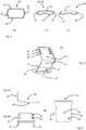
- Figure 1 shows a support element 10 according to the invention, in Figure 1a ) from the profiled underside 14 shown.
- Point 28 marked with an oval denotes the counter profile.
- the marked area does not designate the size of the area provided with the profile 28 but only a region thereof.
- the size and shape depend on the profile rail 20 and how much (in terms of area) the support element 10 is larger than an end region of a profile rail.
- the drawing shows a pattern of profile elements, ribs or stiffeners.
- the feature 29 denotes a longitudinal stop which serves as a receptacle for the longitudinal end 22 of the profile rail 20.
- Feature 12 marks the clamping element 12. In the side view of FIG Figure 1b ) this clamping element is recognizable as a pin-shaped or sleeve-shaped element.
- the upper side 13 is designed flat and table-like, whereas the lower side 14 has the profiling which allows the form fit with a longitudinal end 22 of the profile rail.
- Figure 2 shows a profile rail 20 according to the invention in 3 views (from top to bottom: top, side view, bottom).
- the first longitudinal end 21 is shown on the right, the second longitudinal end 22 on the left.
- the embodiment shown has a hollow cross-sectional profile and is partially open, that is to say cut open.
- the left (second) longitudinal end 22 has the profile 26. It was created by removing the top surface of the profile rail 20 in the end area; the profile therefore consists in this form (essentially) of two longitudinal webs and the receiving opening 17 for the clamping element 12. In the side view of Figure 2b ) it becomes clear that this creates a paragraph 31. At this point - after joining with a support element 10 - the profile rail passes over flush with the support element.
- the upper side 18 has further special features at the opposite, first longitudinal end 21. Here, several openings 23, 24, 25 are shown as examples, holes 23, 24 and elongated hole 25.
- the openings on the top 18 are partially oversized so that a screw head can penetrate the top and only then on the material of the underside is supported. This explains why the same openings 24, 25 on the underside 19 (cf. Figure 2c ) are shown smaller.
- Figure 1 shows one side of the support element 10 with counter profile 28 and longitudinal or transverse reinforcement elements. A longitudinal stop 29 is also shown, up to which the support element 10 can be pushed onto the profile rail 20.
- Figure 3a shows a tubular profile 30 'with two parallel, flat contact surfaces (surfaces) 32, 34 and side surfaces 37, 38.
- Figure 3b a variant 30 is shown as a rectangular hollow profile 36.
- the longitudinal profiling which leads to a further increase in the rigidity of the profile rail 20, is also clearly visible here.
- Figure 3c shows a profile rail 60 according to the prior art with a longitudinal reinforcement as in the hollow profile 36 of Figure 3b ).
- the synopsis of Figure 2a ) The longitudinal end 22 and the profile rail 60 makes it clear that the resulting profile 26, after removing a section of the top 18 from the rectangular hollow profile 36, resembles the classic profile of the profile rail 60. This opens up the possibility of using the support element 10 also with a classic profile rail 60, provided that a receiving opening 17 for the clamping element 12 is also provided in it.
- Figure 4 shows the angle element 40 in an oblique plan view.
- the first leg 41 intended to stop a window or door element, has a plurality of bores 43, 43 ', 43 ", ...
- the arrangement and diameter of the bores / openings is not mandatory, but is shown as an example.
- the second leg 42 of the angle element 40 is intended to rest on the top side 18/32 of a profile rail 20 or an angle profile 60 according to the prior art.
- the edge guides 45 and 46 encompass the upper side 18/32/60 and ensure handling safety.
- the individual bore 44 in the second leg 42 can be seen.
- FIG Figure 5 shown is a side view of the angle with the visible fold / edge guide 45 on the second leg 42.
- Figure 5b shows a plan view of the first leg 41 in a shortened variant compared to FIG Figure 4.
- Figure 5c shows a top view of the second leg 42 with the edge guides 45, 46 and the individual bore in the second leg.
- Figure 6 shows a support angle (angle element) 50 as a further improved version of the angle 40 Figure 4 .
- a second leg 54 is designed to be placed on a profile rail 20 or 60. For this purpose, it has guide edges or webs in the form of beveled edge guides 51, 53, which support an alignment / edge guide on the profile rail 20, 30 and 60, respectively.
- a first leg 52 is arranged essentially at right angles to the first leg 52.
- First and second legs 52, 54 enclose the interior of the angle between them.
- a plurality of openings allows the fitter to set one or more fasteners depending on the window or door element and to make the connection as intended or prescribed.
- the second leg 54 is designed such that the guide webs or edge guides 51, 53 provided laterally in the longitudinal extension of the angled leg encompass the profile rail 60, as in FIG Figure 7 shown.
- the clear space or the clear distance between the two lateral guide webs 51, 53 is selected so that the angle element is guided on the profile rail 60 with little play and remains longitudinally displaceable for adjustment.
- the guide webs 51, 53 each have at least one opening 58, preferably a through-hole, while the surface of the second leg 54 facing the interior manages without holes / through-openings.
- the opening 58 serves as a guide for a fastener which can connect the angle element 50 to the profile rail 60 in a non-positive manner. This can be done either from the left or the right, as defined above in the arrangement logic.
- the angle element 40 from Figure 4 uses the bore 44 for fastening to a profile rail, through which a fastener can be passed. Forces on the angle 40 can lead to a tipping load an axis which is at the apex of the angle 40. As a result, a fastener that has been placed in a profile rail through the bore 44 is subjected to tensile load and the thread must transfer this force to the profile rail.
- FIG. 7 an installation situation is shown with a profile rail 60 which is screwed at its first longitudinal end 21 through an opening 23 on the inner surface of a parapet 59.
- a support element 10 is attached to the second longitudinal end of the profile rail 60; its top is flush with the upper longitudinal edges (guide webs 51, 53) of the profile rail 60 (cf. Figure 3c ) from.
- An angle element 50 is placed on the profile rail in such a way that its guide webs 51, 53 come to lie parallel to the side surfaces 37, 38 of the profile rail 60.
- a fastener 57 uses the opening 58 to connect the angle element 50 to the profile rail.
- a window element (not shown) would be placed on the support element and screwed in a height-adjusted manner to the other leg of the bracket in the desired position.
Abstract
Description
- Bei modernen mehrschaligen Gebäudehüllen ist die sachgerechte Installation von Fenster- und Türrahmen eine wichtige Aufgabe, insbesondere weil eine moderne Gebäudehülle aus einer Vielzahl funktioneller Materialien unterschiedlicher Dicke, Festigkeit und Belastbarkeit besteht. Die Platzierung eines Rahmens erfolgt an einem energietechnisch sinnvollen bzw. durch Bauvorschriften vorgegebenen Bereich der Gebäudehülle, der aber nicht identisch mit einem tragenden Wandabschnitt sein muss. Um z. B. Wandbereiche aus nicht tragendem Material zu überbrücken, wurden schon früher zumindest an der unteren Begrenzung einer Wandöffnung Plattenelemente aus Holz aufgelegt und sowohl mit dem Rahmen als auch der Gebäudehülle verschraubt.
- Diese Möglichkeit ist heute weniger bevorzugt, auch weil moderne Fenster/Türen häufig grossflächig und mit Mehrfachverglasung versehen sind und damit ein hohes Gewicht aufweisen.
- Zur Befestigung von Fenster und Türen bzw. allgemein Bauteilen in Gebäudeöffnungen werden vielfach Montagevorrichtungen verwendet, die sowohl Halte- wie Verstellelemente aufweisen. Wie in der
EP 0 945 577 oder derEP 1 500 767 gezeigt, sind dies Vorrichtungen wie Profilschienen, bei denen an einem Ende eine Gewindestange rechtwinklig angebracht ist. Die Gewindestange kann wiederum Tragplatten oder Halterungen aufnehmen, die entlang der Längsachse des Gewindes verstellbar sind. Dadurch werden das Befestigen in einer Wandöffnung, meist an der Laibung oder Brüstung, aber auch die Justage der Position des Bauteils in drei Dimensionen möglich. Solche Justageelemente sind wegen der zusätzlichen Funktionalität jedoch nicht günstig. Die Einstellmöglichkeiten sind bei Gewindeelementen zwar feinfühlig, machen das ganz aber auch zeitaufwändig. - Das Gebrauchsmuster
DE20 2011 108 043 zeigt eine Vorrichtung zum Fixieren eines Rahmens in einer Wandöffnung unten. Es empfiehlt eine Kombination aus einer Profilschiene mit einem Montagewinkel, dessen Schenkel eine Mehrzahl von Löchern aufweisen. Einer der Schenkel wird an der Profilschiene verschraubt, der andere am Rahmen. Die Höhenjustage des Rahmens gegenüber der Profilschiene erfolgt durch Klötze. - Im Stand der Technik wurde auch vorgeschlagen, die Ableitung der Lasten durch einfache Montagewinkel vorzunehmen bzw. zu unterstützen. Deren Einsatzmöglichkeiten sind jedoch limitiert, insbesondere weil sie in der Regel an der tragenden Gebäudeaussenseite montiert werden müssen. Werden dort jedoch Isolationsschichten aufgebaut, müssen die Verlegepläne der Montagewinkel und der Isolation aufeinander abgestimmt sein.
- Die Aufgabe der vorliegenden Erfindung besteht darin, ein im Vergleich zum Stand der Technik weniger komplexes System anzubieten, das mit wenig Aufwand einsetzbar ist, auf der Baustelle wenig Justageaufwand erfordert und effizient zu produzieren ist.
- Diese Aufgabe wird erfüllt durch eine Vorrichtung mit den Merkmalen nach Anspruch 1. Die Unteransprüche beschreiben weitere nützliche Varianten und Ausführungsformen.
- Eine solche Vorrichtung dient zum Abstützen von Fenster- oder Türelementen an der Laibung bzw. Brüstung einer Wandöffnung. Mit Fenster- und Türelementen sind dabei im weiten Sinne Einbauten bzw. Einbauelemente gemeint, die eine Wandöffnung teilweise oder ganz ausfüllen sollen und in bzw. an bzw. vor einer Wandöffnung eines Gebäudes platziert werden sollen. Im Grundsatz umfasst die Vorrichtung dabei zumindest ein Auflageelement 10 und eine biegesteife Profilschiene 20, 36 bzw. 60. Das Auflageelement 10 weist eine Oberseite 13 und eine Unterseite 14 auf; die Begriffe oben und unten beziehen sich hierbei auf die vorgesehene Einbaulage am unteren Rand der Öffnung, an der Brüstung. Die Profilschiene weist ein erstes Längsende 21 und ein zweites Längsende 22; auf, Ober- und Unterseite werden mit den Referenzzeichen 18 und 19 in analoger Logik wie beim Auflageelement bezeichnet. "Oben" bei der Profilschiene entspricht also "oben" beim Auflageelement, wenn beide sachgemäss verbaut werden. In der Anwendung weist die Unterseite der Profilschiene zur Brüstung (Mauerseite), die Oberseite zum verbauenden Fenster- oder Türelement.
- Das erste Längsende der Profilschiene besitzt Öffnungen zur Aufnahme von Befestigern. Im üblichen technischen Kontext bedeutet dies, die Öffnungen sind in einem flächigen Bereich angeordnet, der an das Längsende der Profilschiene angrenzt. Die Öffnungen sind dabei nicht zwingend ausschliesslich am Rand angeordnet. Mit Befestigern sind dabei vorrangig Schrauben gemeint incl. deren Varianten und technischer Äquivalente, die ein Fachmann auswählt je nach Aufbau der Gebäudewand, des Bodens, dem Gewicht der Fenster- oder Türelemente oder nach Vorgaben der Statik, des Brandschutzes oder einer Wärmeschutzverordnung.
- Mit Öffnungen sind Durchgangsbohrungen, Gewindelöcher oder andere, z.B. durch Prägen vorgesehene Positionen gemeint, an denen das Setzen eines Befestigers möglich ist. Form und Dimension richten sich nach dem Einsatzzweck (Löcher, Langlöcher, etc.). Das erste Längsende ist zur Befestigung der Profilschiene an der Brüstung (an der Laibung bzw. am Boden) vorgesehen, das zweite Längsende dient der Aufnahme des Auflageelementes. Um das zu bewerkstelligen ist am zweite Längsende an der Oberseite ein Profil eingebracht mit Rippen, Bolzen, Vertiefungen und/oder Stiften. Diese können ein symmetrisches bzw. bewusst unsymmetrisches Muster bilden. Die genannten Profilelemente dienen der Festlegung einer bestimmten Lagebeziehung zwischen Profilschiene und Auflageelement.
- Die Oberseite des Auflageelementes ist tischartig flach ausgebildet und die Unterseite weist ein komplementäres Gegenprofil zum Profil auf. Dieses Gegenprofil ist so angelegt, dass es mit dem Profil am zweiten Längsende der Profilschiene einen Formschluss eingeht, wenn die beiden Elemente wie vorgesehen verbunden werden. Damit ist ein direkter und unmitttelbarer, mechanischer Kontakt von Auflageelement und Profilschiene gemeint, der die relative Lage der beiden Elemente zueinander definiert. Weist beispielsweise die Profilschiene eine oder mehrere Längsrippen auf, würde das Gegenprofil als entsprechende Rillen ausgebildet. Besteht das Profil 26 aus erhabenen Stiften, würde das Gegenprofil auf Löchern bzw. Vertiefungen bestehen, in das die Stifte eingreifen können. Generalisierend formuliert, weisen Profilschiene und Auflageelement Elemente auf, die formschlüssig ineinandergreifen können.
- Bevorzugt wird die Vorrichtung so weitergebildet, dass das zweite Längsende der Profilschiene mindestens eine Aufnahmeöffnung für (mindestens) ein Klemmelement aufweist. Dieses Klemmelement ist entsprechend am Auflageelement vorgesehen. Im formschlüssig verbundenen Zustand von Auflageelement und Profilschiene wird also die Verbindung durch das Ineinandergreifen von Klemmelement und Aufnahmeöffnung gesichert. Das Klemmelement am Auflageelement kann hierzu keil- oder kegelförmig ausgebildet werden und greift beim (formschlüssigen) Zusammenstecken in die Durchbohrung (Aufnahmeöffnung 17 in Profilschiene) ein und wird dort durch Reibsitz gehalten. Alternativ kann das Klemmelement als rohrförmige, längs geschlitzte Hülse ausgeführt werden. Diese Hülsensegmente können somit als Federelemente wirken und im Zusammenspiel mit bekannten Haltezungen als Rastelemente verwendet werden, die eine Verriegelung von Aufnahmeelement und Profilschiene bewirken können.
- Die in der vorliegenden Erfindung angesprochene Profilschiene kann ein C, W, U, Doppel-T Querschnittsprofil aufweisen wie aus dem Stand der Technik bekannt. In bevorzugter Ausführung ist die Profilschiene als Rohrprofil ausgeführt und weist mindestens zwei sich gegenüberliegende, eben ausgedehnte und parallele Oberflächen auf. Die hier in den Grundzügen beschriebene Ausführung wäre ein parallel in der Länge abgeflachtes Rohr. In einer bevorzugten Variante wird die Profilschiene mit einem (im Wesentlichen) rechteckigen Querschnittsprofil ausgestaltet, insbesondere als im Wesentlichen rechteckiges Hohlquerschnittsprofil. Das rechteckige Querschnittsprofil kann dabei weitere Versteifungsmerkmale beinhalten, wie in den
Figur 3b gezeigt. Das rechteckig-rohrförmige Querschnittsprofil / Hohlquerschnittsprofil erlaubt eine wesentlich bessere Tragfähigkeit als ein biegesteif ausgeführtes, einfacheres Flacheisen. Ohne diesem Ziel zuwiderzulaufen, können, Ausschnitte, Durchbohrungen oder Aussparungen in der Profilschiene vorgesehen sein, je nachdem wie es die vorgesehene Verwendung erfordert. Die Angabe "weist ein Querschnittsprofil auf" ist dabei mit dem Zusatz "über wesentliche Teile der Gesamtlänge" zu verstehen. - Bevorzugt wird die Profilschiene überwiegend aus Metall, insbesondere aus Stahl gefertigt werden. Die Profilschiene kann mit Schutzüberzügen aus Zink, Lack oder Passivierungsprozessen versehen sein oder aus rostfreiem Stahl gefertigt werden. Die Herstellprozesse für Stahlprofile sind hinlänglich bekannt. Hohlprofile der oben beschriebenen Art können aus flachen Metallbändern oder -platten gebogen und längsverschweisst werden oder aus Rundrohren umgeformt werden.
- Das Auflageelement kann ebenfalls aus Metall (e.g. Zinkdruckguss, Aludruckguss), bevorzugt aber aus Kunststoff, insbesondere aus Thermoplast durch Spritzgiessen, Formpressen oder ähnlichem gefertigt werden. Auf diese Weise lässt sich auch das oben beschriebene Profil in Kunststoff leicht realisieren. Die Unterseite des Auflageelementes kann neben den Profilelementen (Rillen, Vertiefungen, Rippen und/oder Stiften, z.B. angeordnet als Matrix) auch weitere Merkmale aufweisen, die zur Verstärkung des Auflageelementes dienen. Ebenso ist es möglich, jene Profilelemente, die den Formschluss erlauben, um Mittel zu ergänzen, die ein Klemmen oder Verrasten mit der Profilschiene bewirken. Dadurch lässt sich eine verbesserte Handhabung erreichen.
- Die Fläche der Oberseite des Auflageelements wird bevorzugt grösser ausgelegt als seine Kontaktfläche zur Profilschiene, kurz gesagt, es kragt an den Seiten vor. Durch das Ineinandergreifen von Profil / Gegenprofil und die beschriebene Ausführung mit einem Klemmelement entsteht am zweiten Längsende also eine verbreiterte Auflageplattform für den Fenster- bzw. Türrahmen bei der Montage.
- Bevorzugt wird das Gegenprofil so ausgeführt, dass es in exakt einer Position einen Formschluss mit der Profilschiene zulässt. Das erhöht die Anwendungssicherheit, weil es Fehlmontagen verhindern hilft. Das Klemmelement, insbesondere wenn als Rastelement ausgeführt, gibt dem Anwender ein klares Feedback beim Zusammenfügen von Profilschiene und Auflageelement.
- In einer besonders vorteilhaften Ausführung werden Auflageelement und Profilschiene so ausgeführt, dass die Oberseite des Auflageelements im formschlüssig verbundenen Zustand mit der Oberseite der Profilschiene (Referenz 18, 32) flächenbündig abschliesst. Dadurch entsteht eine durchgehende Fläche, die bei der Montage eines Tür- oder Fensterbauteils es ermöglicht, dieses absatzfrei zu verschieben.
- Ein Montagevorgang wird im einfachsten Fall demnach so verlaufen, dass ein Monteur ein Auflageelement und eine Profilschiene zusammenfügt und mittels des Klemmelements dabei automatisch eine Sicherung bewirkt wird. Danach wird die Profilschiene an der Brüstung (Laibung bzw. am Boden) einer Gebäudeöffnung nach den Vorgaben eines Verlege- bzw. Montageplanes befestigt. Dazu dienen üblicherweise Befestiger wie Schrauben, die die in der Profilschiene vorgesehenen Bohrungen nutzen. Diese können verschiedene Durchmesser aufweisen und/oder als Langlöcher ausgelegt sein. Das zweite Ende der Profilschiene mit angefügtem Auflageelement wird dabei in dem Bereich der Gebäudeöffnung angeordnet, wo das Fenster-oder Türelement lokalisiert werden soll. Nachdem eine oder mehrere solcher Kombinationen an der Brüstung (bzw. am Boden) befestigt worden sind, kann das Fenster- bzw. Türelement eingehoben werden. Durch den (flächen-)bündigen Übergang zwischen Profilschiene und Auflageelement ist auch ein ungenaues anfängliches Absetzen unkritisch, das Fensterelement kann danach problemlos in Position geschoben werden.
- Der Vorteil des erfindungsgemässen Auflageelementes besteht darin, dass es dem Monteur eine verbreiterte, ebene Arbeitsfläche zur Feinjustage zur Verfügung stellt. Anders als bei Profilschienen des Standes der Technik ruht das Fensterelement nicht auf schmalen Stegen oder der Profilschiene selbst, sondern auf einer mit der Profilschiene bündigen Fläche. Sollte eine Höhenverstellung mittels Unterlegklötzen erforderlich sein, ist deren Bereitstellung oder Justage ebenfalls erleichtert.
- Eine weitere, vorteilhafte Weiterbildung ergänzt die Kombination von Auflageelement und Profilschiene um ein Winkelelement (Referenz 40 bzw. 50). Dieses Winkelelement weist einen ersten und eine zweiten Schenkel in zueinander rechtwinkliger Anordnung auf. Die Aufgabe des Winkelelements ist die mechanische Verbindung von Profilschiene und Fenster- bzw. Türelement. Es dient weniger dem Lastabtrag des Eigengewichts sondern vielmehr der Ableitung von dynamischen Lasten wie Druck und Sog durch Wind. Um die Handhabung einfacher und sicherer zu machen, weist der zweite Schenkel hierzu zwei parallel angeordnete, abgekantete Randführungen auf, deren Abstand im Wesentlichen der Breite der Profilschiene an deren Oberseite entspricht. Diese Randführungen, die sich durch Abkanten der Längsränder des zweiten Schenkels herstellen lassen, wirken als seitliche Führung, wenn der Winkel auf die Profilschiene aufgelegt wird. Für den Fachmann nachvollziehbar ist "im Wesentlichen der Breite der Oberseite der Profilschiene" entsprechend so zu verstehen, dass die Auslegung mit so viel Spiel erfolgt, dass sich das Winkelelement leicht entlang der Profilschiene bewegen lässt. Es sei darauf hingewiesen, dass dieses Winkelelement auch mit gleich breit gefertigten Schienen gemäss dem Stand der Technik nützlich eingesetzt werden kann, also Schienen mit U, W, C oder Doppel-T Profil (
Fig. 3c ). - Der erste Schenkel des Winkelelementes ist dazu ausgelegt, mit dem Tür- oder Fensterbauteil verbunden zu werden. Dies kann bekanntermassen mit Schrauben bzw. Selbstbohrschrauben geschehen oder technisch äquivalent mit Nieten, Kleben oder anderen Verbindungstechniken. Der erste Schenkel kann dazu mit einer Mehrzahl von Bohrungen versehen sein. Mit Bohrungen können dabei Durchbohrungen, Durchgangsöffnungen oder auch Sacklöcher gemeint sein, die lediglich Führungshilfen für einen Befestiger darstellen. Die Mehrzahl an Bohrungen erlaubt dem Monteur, die für den Einsatzzweck beste Position für den oder die Befestiger auszuwählen.
- Die Befestigung des zweiten Schenkels, der bestimmungsgemäss auf der Profilschiene aufliegt, kann durch genau eine Schraube erfolgen, welche in die zum Innenraum weisende Oberfläche des zweiten Schenkels eingebracht wird. Diese Festlegung erscheint auf den ersten Blick erstaunlich, da damit dem Monteur ein Freiheitsgrad genommen wird. Jedoch erlaubt diese Reduktion auf eine Soll-Position (Referenz 44), dass die lastübertragungstechnisch optimierte Position gewählt werden muss. Da die Profilschiene (quer-)profiliert ausgeführt werden kann, wird auf diese Weise verhindert, dass ein Monteur eine ungünstige Platzierung für den Befestiger wählt. Erreicht wird diese Vorgabe der Position dadurch, dass der zweite Schenkel mit genau einer Bohrung versehen wird. Für die Bedeutung des Begriffs Bohrung gilt analog das oben Gesagte.
- In einer besonders bevorzugten Ausführung wird diese einzelne Bohrung aussermittig im vom Winkelscheitel abgewandten Endbereich des zweiten Schenkels angebracht. Bevorzugt wird der Endbereich ein Drittel der Schenkellänge umfassen, die aussermittige Position wird näher am Schenkelrand als in der Mitte gewählt.
- Die Anwendung des Winkelelements erfolgt nach dem Einheben und Ausrichten des Fensterelementes in seiner Sollposition auf dem Auflageelement relativ zur Gebäudeöffnung. Das Winkelelement wird mit seinem zweiten Schenkel aufgelegt und wird durch die seitlich die Profilschiene umfassenden Randführungen zwangsläufig ausgerichtet. Durch Schieben entlang der Profilschiene wird das Winkelelement so in Richtung Fensterelement verschoben, bis der erste Schenkel am Rahmen anschlägt. Dessen Schenkellänge wird so gewählt, dass er die nötige Lastableitung gewährleistet, aber nicht das optische Erscheinungsbild des Fensterelementes beeinträchtigt. Um die Klötze einer evtl. Höhen-Justage zu überbrücken, können Winkelelemente mit verschiedenen Längen des ersten Schenkels vorgesehen werden, während die zweite Schenkellänge (bis auf Sonderbauformen) für alle Varianten gleich gewählt werden kann.
- Die Anordnung aus Profilschiene 20, 60, Auflageelement 10 und einem Winkelelement 40, 50 kann in einer zweiten Bauform betrachtet werden. Das Winkelelement weist einen ersten und eine zweiten Schenkel in zueinander rechtwinkliger Anordnung auf. Der zweite Schenkel weist dabei zwei parallele, abgekantete, vom Innenraum des Winkels wegweisende Randführungen aufweist, deren lichter Abstand zueinander im Wesentlichen der Breite der Profilschiene an deren Oberseite entspricht.
- Die abgekanteten Randführungen sind also als flächige Führungsstege ausgeführt, die im montierten Zustand parallel zu den Seitenflächen der Profilschiene angeordnet sind. Auch hier ist die Orientierung gemeint wie eingangs beschrieben. Dabei ist bevorzugt, dass die abgekanteten Randführungen mindestens eine Öffnung (Bohrung, Durchbohrung, Prägung) aufweisen, bevorzugt mindestens eine Öffnung pro Randführung.
- Wird diese Ausführung realisiert, kann die zum Innenraum weisende Oberfläche des zweiten Schenkels ohne Bohrungen bzw. Durchtrittsöffnungen auskommen.
-
-
Figur 1 zeigt ein Auflageelement 10 einmal in Draufsicht der Unterseite (Fig. 1a ) und in Seitenansicht (Fig. 1b ) von der Verbindungsstelle zur Profischiene 20 her. -
Figur 2 zeigt eine Profilschiene 20 gemäss der Erfindung, 2a) in Draufsicht die Oberseite, 2b) eine Seitenansicht und 2c) die Unterseite. -
Figur 3 zeigt schematische Rohrquerschnitte, die für eine Profilschiene 20 grundsätzlich Verwendung finden könnten.Figur 3a ) ein abgeflachtes Rohrprofil,Figur 3b ) ein erfindungsgemässes Hohlquerschnittsprofil undFigur 3c ) eine U, W bzw. C-Profil . -
Figur 4 zeigt ein Winkelelement 40 (erste Bauform) in Schräg-3D Ansicht -
Figur 5a ) zeigt eine Seitenansicht,Figur 5b ) eine Draufsicht auf den ersten Schenkel 41, Figur 5c) eine Draufsicht auf den zweiten Schenkel 42. -
Figur 6 zeigt ein Winkelelement 50 in zweiter Bauform -
Figur 7 zeigt eine Einbausituation aus Profilschiene 60, Auflageelement 10 und Winkel 50 an einer Brüstung 59 -
Figur 1 zeigt ein Auflageelement 10 gemäss der Erfindung, inFigur 1a ) von der profilierten Unterseite 14 gezeigt. Die mit einem Oval gekennzeichnete Stelle 28 bezeichnet das Gegenprofil. Die markierte Fläche bezeichnet dabei nicht die Grösse der mit dem Profil 28 versehenen Fläche sondern nur einen Bereich davon. Grösse und Form hängen von der Profilschiene 20 ab und wieviel (flächenmässig) grösser das Auflageelement 10 ist als ein Endbereich einer Profilschiene. Die Zeichnung zeigt ein Muster aus Profilelementen, Rippen bzw. Versteifungen. Das Merkmal 29 bezeichnet einen Längsanschlag, der als Aufnahme für das Längsende 22 der Profilschiene 20 dient. Merkmal 12 markiert das Klemmelement 12. In der Seitenansicht vonFigur 1b ) ist dieses Klemmelement als zapfen- bzw. hülsenförmiges Element erkennbar. In der Seitenansicht wird auch erkennbar, dass die Oberseite 13 flach und tischartig ausgestaltet ist, wogegen die Unterseite 14 die Profilierung aufweist, welche den Formschluss mit einem Längsende 22 der Profilschiene zulässt. -
Figur 2 zeigt eine erfindungsgemässe Profilschiene 20 in 3 Ansichten (von oben nach unten: Oberseite, Seitenansicht, Unterseite). Das erste Längsende 21 ist hierbei rechts, das zweite Längsende 22 links gezeigt. Die gezeigte Ausführungsform hat ein hohles Querschnittsprofil und ist teilweise geöffnet, d.h. an- bzw. aufgeschnitten. - Das linke (zweite) Längsende 22 weist das Profil 26 auf. Es entstand durch das Entfernen der Deckfläche der Profilschiene 20 im Endbereich, das Profil besteht deswegen in dieser Form (im Wesentlichen) aus zwei Längsstegen und der Aufnahmeöffnung 17 für das Klemmelement 12. In der Seitenansicht von
Figur 2b ) wird deutlich, dass dadurch ein Absatz 31 entsteht. An dieser Stelle geht auch - nach dem Zusammenfügen mit einem Auflageelement 10 - die Profilschiene flächenbündig über zum Auflageelement. Die Oberseite 18 weist am entgegengesetzten, ersten Längsende 21 weitere Besonderheiten auf. Hier sind mehrere Öffnungen 23, 24, 25 exemplarisch gezeigt, Löcher 23, 24 sowie Langloch 25. Da die Profilschiene 20 hier als Hohlprofil ausgelegt ist, sind die Öffnungen auf der Oberseite 18 teilweise so überdimensioniert, dass ein Schraubenkopf die Oberseite durchtreten kann und erst auf dem Material der Unterseite sich abstützt. Das erklärt, warum dieselben Öffnungen 24, 25 auf der Unterseite 19 (cf.Fig. 2c ) kleiner abgebildet sind. -
Figur 1 zeigt eine Seite des Auflageelementes 10 mit Gegenprofil 28 und Längs- bzw. Querverstärkungselementen. Eingezeichnet ist ebenfalls ein Längsanschlag 29, bis zu dem das Auflageelement 10 auf die Profilschiene 20 aufgeschoben werden kann. -
Figur 3a ) zeigt ein Rohrprofil 30' mit zwei parallelen, flachen Anlageflächen (Oberflächen) 32, 34 und Seitenflächen 37, 38. InFigur 3b ) ist eine Variante 30 als Rechteck-Hohlprofil 36 gezeigt. Deutlich erkennbar ist hier auch die Längs-Profilierung, die zu einer weiteren Erhöhung der Steifigkeit der Profilschiene 20 führt.Figur 3c zeigt eine Profilschiene 60 gemäss Stand der Technik mit einer Längsverstärkung wie beim Hohlprofil 36 vonFigur 3b ). Die Zusammenschau vonFigur 2a ), Längsende 22 und der Profilschiene 60 macht klar, dass das resultierende Profil 26 nach Wegnahme eines Abschnitts der Oberseite 18 vom Rechteck-Hohlprofil 36 dem klassischen Profil der Profilschiene 60 gleicht. Damit eröffnet sich die Möglichkeit, das Auflageelement 10 auch mit einer klassischen Profilschiene 60 zu verwenden, sofern bei ihr ebenfalls eine Aufnahmeöffnung 17 für das Klemmelement 12 vorgesehen wird. -
Figur 4 zeigt das Winkelelement 40 in einer schrägen Aufsicht. Der erste Schenkel 41, gedacht zum Anschlag ein Fenster- bzw. Türelement, weist eine Vielzahl von Bohrungen 43, 43', 43",... Die Anordnung und Durchmesser der Bohrungen / Öffnungen ist nicht zwingend, sondern exemplarisch dargestellt. - Der zweite Schenkel 42 des Winkelelements 40 ist zur Auflage auf der Oberseite 18/32 einer Profilschiene 20 oder eines Winkelprofils 60 nach Stand der Technik vorgesehen. Die Randführungen 45 und 46 umgreifen die Oberseite 18/32/60 und sorgen für die Handhabungssicherheit. Im Endbereich 48 ist die einzelne Bohrung 44 im zweiten Schenkel 42 erkennbar. Weitere Darstellungen des Winkelelements 40 sind in
Figur 5 gezeigt.Figur 5a ) ist eine Seitenansicht auf den Winkel mit der sichtbaren Abkantung / Randführung 45 am zweiten Schenkel 42.Figur 5b ) zeigt eine Draufsicht auf den ersten Schenkel 41 in einer verkürzten Variante im Vergleich zuFigur 4. Figur 5c ) zeigt eine Draufsicht auf den zweiten Schenkel 42 mit den Randführungen 45, 46 und der einzelnen Bohrung im zweiten Schenkel. -
Figur 6 zeigt einen Abstützwinkel (Winkelelement) 50 als eine weiter verbesserte Version des Winkels 40 ausFigur 4 . Ein zweiter Schenkel 54 ist ausgelegt um auf eine Profilschiene 20 bzw. 60 aufgelegt zu werden. Dazu weist er Führungskanten bzw. -stege in Form von abgekanteten Randführungen 51, 53 auf, die eine Ausrichtung / Randführung auf der Profilschiene 20, 30 bzw. 60 unterstützen. Ein erster Schenkel 52 ist im Wesentlichen rechtwinklig zum ersten Schenkel 52 angeordnet. Erster und zweiter Schenkel 52, 54 schliessen zwischen sich den Innenraum des Winkels ein.
Am ersten Schenkel 52 sind eine Mehrzahl von Bohrungen, Öffnungen, Langlöcher bzw. Verbindungspunkte 56, 56' vorgesehen, um den Abstützwinkel sachgerecht am Bauteil (Fenster, Türe) befestigen zu können. Eine Mehrzahl von Öffnungen erlaubt dem Monteur dabei, je nach Fenster- bzw. Türelement einen oder mehrere Befestiger zu setzen und die Verbindung so auszuführen wie vorgesehen bzw. vorgeschrieben. - Der zweite Schenkel 54 ist so ausgeführt, dass die in Längserstreckung des Winkelschenkels seitlich vorgesehenen Führungsstege bzw. Randführungen 51, 53 die Profilschiene 60 umgreifen, wie in
Figur 7 gezeigt. Der lichte Raum bzw. der lichte Abstand zwischen den beiden seitlichen Führungsstegen 51, 53 wird so gewählt, dass das Winkelelement auf der Profilschiene 60 mit geringem Spiel geführt ist und zur Justage längsverschieblich bleibt. - Die Führungsstege 51, 53 weisen jeweils mindestens eine Öffnung 58, bevorzugt eine Durchgangsbohrung, auf, während die zum Innenraum weisende Oberfläche des zweiten Schenkels 54 ohne Bohrungen / Durchtrittsöffnungen auskommt. Wie in
Figur 7 weiter gezeigt, dient die Öffnung 58 als Führung für einen Befestiger, der das Winkelelement 50 mit der Profilschiene 60 kraftschlüssig verbinden kann. Dies kann wahlweise von links oder rechts erfolgen, in der Anordnungslogik wie oben definiert. - Diese auf den ersten Blick ungewöhnliche Verbindung - der Befestiger wird parallel zur Brüstung 59 angeordnet - hat sich als besonders vorteilhaft erwiesen. Das Winkelelement 40 aus
Figur 4 nutzt zur Befestigung an einer Profilschiene die Bohrung 44, durch die ein Befestiger geführt werden kann. Kräfte auf den Winkel 40 können zu einer Kippbelastung führen mit einer Achse, die im Scheitel des Winkels 40 liegt. Dadurch wird ein Befestiger, der durch die Bohrung 44 in eine Profilschiene gesetzt wurde, auf Zug belastet und das Gewinde muss diese Kraft an die Profilschiene ableiten. Ausserdem wird ein gesetzter Befestiger, je nach Länge, in das Untergrundmaterial von Brüstung / Laibung getrieben werden, was - je nach Härte dieses Untergrunds - das Setzen des Befestigers erschwert oder zu Bohrstaub führt. Bei einem Setzen eines Befestigers 57 "seitlich" wie inFigur 7 gezeigt, gibt es diese Gefahr nicht. Zudem wird bei einer Kippbewegung analog obiger Beschreibung der Befestiger 57 jetzt nicht auf Zug belastet, sondern auf Scherung. Somit ist der gesamte Kern des Befestigers am Lastabtrag beteiligt und nicht nur sein Gewinde. Das erklärt, warum - je nach Auslegung - ein einzelner Befestiger pro Verbindung Winkel-Profilschiene ausreichen kann. - In der
Figur 7 wird eine Einbausituation gezeigt mit einer Profilschiene 60, die an ihrem ersten Längsende 21 durch eine Öffnung 23 an der Innenfläche einer Brüstung 59 verschraubt ist. Am zweiten Längsende der Profilschiene 60 ist ein Auflageelement 10 angebracht, seine Oberseite schliesst bündig mit den oberen Längskanten (Führungsstege 51, 53) der Profilschiene 60 (vgl.Figur 3c ) ab. Ein Winkelelement 50 ist auf der Profilschiene so aufgelegt, dass seine Führungsstege 51, 53 parallel zu den Seitenflächen 37, 38 der Profilschiene 60 zu liegen kommen. Ein Befestiger 57 nutzt die Öffnung 58 um das Winkelelement 50 mit der Profilschiene zu verbinden. Ein (nicht gezeigtes) Fensterelement würde auf dem Auflageelement aufgesetzt und höhenjustiert mit dem anderen Schenkel des Winkels in Sollposition verschraubt. - Die dargestellten und beschriebenen Merkmale können individuell und im Zusammenwirken wesentlich sein.
Claims (16)
- Vorrichtung zum Abstützen von Fenster- oder Türelementen an einer Wandöffnung, mit- zumindest einem Auflageelement (10) mit einer Oberseite (13) und einer Unterseite (14),- einer biegesteifen Profilschiene (20, 60), die eine Oberseite (18), eine Unterseite (19), ein erstes Längsende (21) und ein zweites Längsende (22) aufweist, wobei- das erste Längsende (21) Öffnungen (23, 24, 25) zur Aufnahme von Befestigern aufweist und- das zweite Längsende (22) an der Oberseite (18) ein Profil (26) aufweist mit Rippen, Bolzen, Vertiefungen und/oder Stiften;dadurch gekennzeichnet, dass
die Oberseite (13) des Auflageelementes (10) tischartig flach ausgebildet ist und die Unterseite (14) ein Gegenprofil (28) aufweist, das komplementär zum Profil (26) am zweiten Längsende (22) der Profilschiene (20, 60) ausgebildet und dadurch formschlüssig mit ihm verbindbar ist. - Vorrichtung nach Anspruch 1, dadurch gekennzeichnet, dass das zweite Längsende (22) der Profilschiene (20) mindestens eine Aufnahmeöffnung (17) für ein Klemmelement (12) aufweist.
- Vorrichtung nach Anspruch 1-2, dadurch gekennzeichnet, dass das Auflageelement (10) mindestens ein Klemmelement (12) aufweist.
- Vorrichtung nach Anspruch 1-3, dadurch gekennzeichnet, dass die Profilschiene (20) ein Rohrprofil (30) aufweist mit mindestens zwei sich gegenüberliegenden, eben ausgedehnten und parallelen Oberflächen (32, 34).
- Vorrichtung nach Anspruch 4, dadurch gekennzeichnet, dass die Profilschiene (20) über ein im Wesentlichen rechteckiges Querschnittsprofil (36) verfügt.
- Vorrichtung nach Anspruch 5, dadurch gekennzeichnet, dass das Querschnittsprofil (36) ein Hohlquerschnittsprofil ist.
- Vorrichtung nach Anspruch 1-6, dadurch gekennzeichnet, dass die Profilschiene (20, 60) überwiegend aus Metall, insbesondere aus Stahl besteht.
- Vorrichtung nach Anspruch 1-7, dadurch gekennzeichnet, dass das Auflageelement (10) aus Kunststoff, insbesondere aus einem Thermoplast besteht.
- Vorrichtung nach Anspruch 1-8, dadurch gekennzeichnet, dass das Gegenprofil (28) des Auflageelements aus einer Matrix von Rillen, Vertiefungen, Rippen und/oder Stiften besteht.
- Vorrichtung nach Anspruch 1-9, dadurch gekennzeichnet, dass die Oberseite (13) des Auflageelements (10) im formschlüssig verbundenen Zustand mit der Profilschiene (20) flächenbündig abschliesst mit der Oberseite (18) der Profilschiene (20).
- Vorrichtung nach Anspruch 1-10, dadurch gekennzeichnet, dass das Auflageelement (10) im formschlüssig verbundenen Zustand mit der Profilschiene (20) durch das Ineinandergreifen von Klemmelement (12) und Aufnahmeöffnung (17) gesichert wird.
- Anordnung aus einer Vorrichtung nach Anspruch 1-11 und einem Winkelelement (40, 50), das einen ersten (41, 52) und eine zweiten Schenkel (42, 54) in zueinander rechtwinkliger Anordnung aufweist, dadurch gekennzeichnet, dass der zweite Schenkel (42, 54) zwei parallele, abgekantete, vom Innenraum des Winkels wegweisende Randführungen aufweist (45, 46, 51, 53), deren lichter Abstand zueinander im Wesentlichen der Breite der Profilschiene (20, 60) an deren Oberseite (18) entspricht.
- Anordnung nach Anspruch 12, dadurch gekennzeichnet, dass die abgekanteten Randführungen (45, 46, 51, 53) als flächige Führungsstege ausgeführt sind, die im montierten Zustand parallel zu den Seitenflächen (37, 38) der Profilschiene (60) angeordnet sind.
- Anordnung nach Anspruch 12-13, dadurch gekennzeichnet, dass die abgekanteten Randführungen (45, 46, 51, 53) mindestens eine Öffnung, bevorzugt mindestens eine Öffnung pro Randführung (45, 46, 51, 53) aufweisen.
- Anordnung nach Anspruch 12-14, dadurch gekennzeichnet, dass die zum Innenraum weisende Oberfläche des zweiten Schenkels (54) ohne Bohrungen bzw. Durchtrittsöffnungen auskommt.
- Anordnung nach Anspruch 12 - 13, dadurch gekennzeichnet, dass die zum Innenraum weisende Oberfläche des zweiten Schenkels mit genau einer Bohrung (44) versehen ist.
Priority Applications (1)
| Application Number | Priority Date | Filing Date | Title |
|---|---|---|---|
| PL20157435T PL3696362T3 (pl) | 2019-02-15 | 2020-02-14 | Urządzenie do podpierania elementów okiennych lub drzwiowych |
Applications Claiming Priority (1)
| Application Number | Priority Date | Filing Date | Title |
|---|---|---|---|
| EP19157329.4A EP3696361B8 (de) | 2019-02-15 | 2019-02-15 | Vorrichtung zum abstützen von fenster- oder türelementen |
Publications (3)
| Publication Number | Publication Date |
|---|---|
| EP3696362A1 true EP3696362A1 (de) | 2020-08-19 |
| EP3696362B1 EP3696362B1 (de) | 2022-03-30 |
| EP3696362B8 EP3696362B8 (de) | 2022-05-04 |
Family
ID=65443691
Family Applications (2)
| Application Number | Title | Priority Date | Filing Date |
|---|---|---|---|
| EP19157329.4A Active EP3696361B8 (de) | 2019-02-15 | 2019-02-15 | Vorrichtung zum abstützen von fenster- oder türelementen |
| EP20157435.7A Active EP3696362B8 (de) | 2019-02-15 | 2020-02-14 | Vorrichtung zum abstützen von fenster- oder türelementen |
Family Applications Before (1)
| Application Number | Title | Priority Date | Filing Date |
|---|---|---|---|
| EP19157329.4A Active EP3696361B8 (de) | 2019-02-15 | 2019-02-15 | Vorrichtung zum abstützen von fenster- oder türelementen |
Country Status (2)
| Country | Link |
|---|---|
| EP (2) | EP3696361B8 (de) |
| PL (2) | PL3696361T3 (de) |
Citations (8)
| Publication number | Priority date | Publication date | Assignee | Title |
|---|---|---|---|---|
| EP0945577A2 (de) | 1998-03-23 | 1999-09-29 | SFS Industrie Holding AG | Vorrichtung zum Abstützen von Fenster- oder Türrahmen an der Begrenzung einer Wandöffnung |
| EP1500767A2 (de) | 2003-07-25 | 2005-01-26 | SFS intec Holding AG | Vorrichtung zum Abstützen und Befestigen von Fenster- oder Türrahmen an der Begrenzung einer Wandöffnung |
| KR100899787B1 (ko) * | 2008-11-18 | 2009-05-28 | 데카코리아(주) | 고정브래킷 |
| KR20100001682U (ko) * | 2008-08-06 | 2010-02-17 | 김명근 | 창호 설치용 결속구 및 이 결속구에 설치되는 창틀간격조절구 |
| DE202011108043U1 (de) | 2011-11-18 | 2012-01-12 | Knelsen Gmbh | Vorrichtung zum Fixieren eines Baukörpers in einer Gebäudeöffnung |
| FR2966211A1 (fr) * | 2010-10-15 | 2012-04-20 | Tordo Belgrano Sa | Equerre de fixation et mode de pose |
| EP2896774A1 (de) * | 2014-01-20 | 2015-07-22 | Knelsen GmbH | Vorrichtung zum Fixieren eines Baukörpers |
| KR101583352B1 (ko) * | 2015-06-22 | 2016-01-19 | 주식회사 대진테크 | 창틀 고정용 브라켓 |
-
2019
- 2019-02-15 EP EP19157329.4A patent/EP3696361B8/de active Active
- 2019-02-15 PL PL19157329.4T patent/PL3696361T3/pl unknown
-
2020
- 2020-02-14 EP EP20157435.7A patent/EP3696362B8/de active Active
- 2020-02-14 PL PL20157435T patent/PL3696362T3/pl unknown
Patent Citations (8)
| Publication number | Priority date | Publication date | Assignee | Title |
|---|---|---|---|---|
| EP0945577A2 (de) | 1998-03-23 | 1999-09-29 | SFS Industrie Holding AG | Vorrichtung zum Abstützen von Fenster- oder Türrahmen an der Begrenzung einer Wandöffnung |
| EP1500767A2 (de) | 2003-07-25 | 2005-01-26 | SFS intec Holding AG | Vorrichtung zum Abstützen und Befestigen von Fenster- oder Türrahmen an der Begrenzung einer Wandöffnung |
| KR20100001682U (ko) * | 2008-08-06 | 2010-02-17 | 김명근 | 창호 설치용 결속구 및 이 결속구에 설치되는 창틀간격조절구 |
| KR100899787B1 (ko) * | 2008-11-18 | 2009-05-28 | 데카코리아(주) | 고정브래킷 |
| FR2966211A1 (fr) * | 2010-10-15 | 2012-04-20 | Tordo Belgrano Sa | Equerre de fixation et mode de pose |
| DE202011108043U1 (de) | 2011-11-18 | 2012-01-12 | Knelsen Gmbh | Vorrichtung zum Fixieren eines Baukörpers in einer Gebäudeöffnung |
| EP2896774A1 (de) * | 2014-01-20 | 2015-07-22 | Knelsen GmbH | Vorrichtung zum Fixieren eines Baukörpers |
| KR101583352B1 (ko) * | 2015-06-22 | 2016-01-19 | 주식회사 대진테크 | 창틀 고정용 브라켓 |
Also Published As
| Publication number | Publication date |
|---|---|
| EP3696362B1 (de) | 2022-03-30 |
| PL3696362T3 (pl) | 2022-06-20 |
| EP3696361B8 (de) | 2022-05-04 |
| EP3696362B8 (de) | 2022-05-04 |
| EP3696361A1 (de) | 2020-08-19 |
| PL3696361T3 (pl) | 2022-07-25 |
| EP3696361B1 (de) | 2022-03-30 |
Similar Documents
| Publication | Publication Date | Title |
|---|---|---|
| EP2186966B1 (de) | Fassadenkonstruktion | |
| EP0945577A2 (de) | Vorrichtung zum Abstützen von Fenster- oder Türrahmen an der Begrenzung einer Wandöffnung | |
| EP3235983A1 (de) | Schiebetüranlage und schienenvorrichtung | |
| DE102008059464A1 (de) | Verbindungssystem und Verbindungsvorrichtung | |
| EP3636844B1 (de) | Trockenbau-tragrahmen für eine schiebetür | |
| EP1785535B1 (de) | Verbindungsbeschlag und Verfahren zum Verbinden eines Holzträgers mit einer Tragstruktur aus Holz | |
| AT515020B1 (de) | Fensterbank-Anschlusseinheit | |
| WO2018024447A1 (de) | Verbinder | |
| DE202014102470U1 (de) | Befestigungseinrichtung für einen Holm oder eine Leiste an einem C-Profil | |
| EP2933507A1 (de) | Stossverbindungsanordnung, fenster-/türrahmen oder fenster-/türflügelrahmen sowie rahmenprofilelement | |
| DE102010022415B4 (de) | Montagelasche für abgehängte Decken | |
| EP1081300A2 (de) | Bauwerk | |
| EP3293336B1 (de) | Halteschiene für einen französischen balkon sowie haltevorrichtung und anordnung dafür | |
| EP3696362B1 (de) | Vorrichtung zum abstützen von fenster- oder türelementen | |
| DE102019114492A1 (de) | Befestigungssystem mit Kraftverteilung | |
| DE102004037548B4 (de) | Ausrichtvorrichtung und/oder Aufhängevorrichtungssystem | |
| DE3241424C2 (de) | Verbindungseinrichtung | |
| DE10355495A1 (de) | Zerlegbares Gerüst | |
| EP3263788B1 (de) | Verbindung zweier holzbalken | |
| DE102010020278A1 (de) | Vorrichtung zur Bereitstellung eines Befestigungspunktes an einem Profilelement | |
| EP1201158B1 (de) | Aufbewahrungsmöbel, insbesondere für Büroeinrichtungen | |
| EP1717452A1 (de) | Verbindungsvorrichtung zum Verbinden von zwei Bauteilen | |
| DE102006020259A1 (de) | Verbindungsvorrichtung zum Verbinden von zwei Bauteilen | |
| DE102005032063B3 (de) | Beschlag zur Klemmbefestigung einer Glasscheibe | |
| DE102009013146A1 (de) | Beschlagelement |
Legal Events
| Date | Code | Title | Description |
|---|---|---|---|
| PUAI | Public reference made under article 153(3) epc to a published international application that has entered the european phase |
Free format text: ORIGINAL CODE: 0009012 |
|
| STAA | Information on the status of an ep patent application or granted ep patent |
Free format text: STATUS: THE APPLICATION HAS BEEN PUBLISHED |
|
| AK | Designated contracting states |
Kind code of ref document: A1 Designated state(s): AL AT BE BG CH CY CZ DE DK EE ES FI FR GB GR HR HU IE IS IT LI LT LU LV MC MK MT NL NO PL PT RO RS SE SI SK SM TR |
|
| AX | Request for extension of the european patent |
Extension state: BA ME |
|
| STAA | Information on the status of an ep patent application or granted ep patent |
Free format text: STATUS: REQUEST FOR EXAMINATION WAS MADE |
|
| 17P | Request for examination filed |
Effective date: 20210219 |
|
| RBV | Designated contracting states (corrected) |
Designated state(s): AL AT BE BG CH CY CZ DE DK EE ES FI FR GB GR HR HU IE IS IT LI LT LU LV MC MK MT NL NO PL PT RO RS SE SI SK SM TR |
|
| GRAP | Despatch of communication of intention to grant a patent |
Free format text: ORIGINAL CODE: EPIDOSNIGR1 |
|
| STAA | Information on the status of an ep patent application or granted ep patent |
Free format text: STATUS: GRANT OF PATENT IS INTENDED |
|
| INTG | Intention to grant announced |
Effective date: 20211123 |
|
| GRAS | Grant fee paid |
Free format text: ORIGINAL CODE: EPIDOSNIGR3 |
|
| GRAA | (expected) grant |
Free format text: ORIGINAL CODE: 0009210 |
|
| STAA | Information on the status of an ep patent application or granted ep patent |
Free format text: STATUS: THE PATENT HAS BEEN GRANTED |
|
| REG | Reference to a national code |
Ref country code: DE Ref legal event code: R081 Ref document number: 502020000851 Country of ref document: DE Owner name: SFS GROUP INTERNATIONAL AG, CH Free format text: FORMER OWNER: SFS INTEC HOLDING AG, HEERBRUGG, CH |
|
| AK | Designated contracting states |
Kind code of ref document: B1 Designated state(s): AL AT BE BG CH CY CZ DE DK EE ES FI FR GB GR HR HU IE IS IT LI LT LU LV MC MK MT NL NO PL PT RO RS SE SI SK SM TR |
|
| REG | Reference to a national code |
Ref country code: GB Ref legal event code: FG4D Free format text: NOT ENGLISH |
|
| REG | Reference to a national code |
Ref country code: CH Ref legal event code: EP |
|
| RAP4 | Party data changed (patent owner data changed or rights of a patent transferred) |
Owner name: SFS GROUP INTERNATIONAL AG |
|
| REG | Reference to a national code |
Ref country code: CH Ref legal event code: PK Free format text: BERICHTIGUNG B8 Ref country code: DE Ref legal event code: R096 Ref document number: 502020000851 Country of ref document: DE |
|
| REG | Reference to a national code |
Ref country code: AT Ref legal event code: REF Ref document number: 1479340 Country of ref document: AT Kind code of ref document: T Effective date: 20220415 |
|
| REG | Reference to a national code |
Ref country code: IE Ref legal event code: FG4D Free format text: LANGUAGE OF EP DOCUMENT: GERMAN |
|
| REG | Reference to a national code |
Ref country code: SE Ref legal event code: TRGR |
|
| REG | Reference to a national code |
Ref country code: LT Ref legal event code: MG9D |
|
| PG25 | Lapsed in a contracting state [announced via postgrant information from national office to epo] |
Ref country code: RS Free format text: LAPSE BECAUSE OF FAILURE TO SUBMIT A TRANSLATION OF THE DESCRIPTION OR TO PAY THE FEE WITHIN THE PRESCRIBED TIME-LIMIT Effective date: 20220330 Ref country code: NO Free format text: LAPSE BECAUSE OF FAILURE TO SUBMIT A TRANSLATION OF THE DESCRIPTION OR TO PAY THE FEE WITHIN THE PRESCRIBED TIME-LIMIT Effective date: 20220630 Ref country code: LT Free format text: LAPSE BECAUSE OF FAILURE TO SUBMIT A TRANSLATION OF THE DESCRIPTION OR TO PAY THE FEE WITHIN THE PRESCRIBED TIME-LIMIT Effective date: 20220330 Ref country code: HR Free format text: LAPSE BECAUSE OF FAILURE TO SUBMIT A TRANSLATION OF THE DESCRIPTION OR TO PAY THE FEE WITHIN THE PRESCRIBED TIME-LIMIT Effective date: 20220330 Ref country code: BG Free format text: LAPSE BECAUSE OF FAILURE TO SUBMIT A TRANSLATION OF THE DESCRIPTION OR TO PAY THE FEE WITHIN THE PRESCRIBED TIME-LIMIT Effective date: 20220630 |
|
| REG | Reference to a national code |
Ref country code: NL Ref legal event code: MP Effective date: 20220330 |
|
| PG25 | Lapsed in a contracting state [announced via postgrant information from national office to epo] |
Ref country code: LV Free format text: LAPSE BECAUSE OF FAILURE TO SUBMIT A TRANSLATION OF THE DESCRIPTION OR TO PAY THE FEE WITHIN THE PRESCRIBED TIME-LIMIT Effective date: 20220330 Ref country code: GR Free format text: LAPSE BECAUSE OF FAILURE TO SUBMIT A TRANSLATION OF THE DESCRIPTION OR TO PAY THE FEE WITHIN THE PRESCRIBED TIME-LIMIT Effective date: 20220701 Ref country code: FI Free format text: LAPSE BECAUSE OF FAILURE TO SUBMIT A TRANSLATION OF THE DESCRIPTION OR TO PAY THE FEE WITHIN THE PRESCRIBED TIME-LIMIT Effective date: 20220330 |
|
| PG25 | Lapsed in a contracting state [announced via postgrant information from national office to epo] |
Ref country code: NL Free format text: LAPSE BECAUSE OF FAILURE TO SUBMIT A TRANSLATION OF THE DESCRIPTION OR TO PAY THE FEE WITHIN THE PRESCRIBED TIME-LIMIT Effective date: 20220330 |
|
| PG25 | Lapsed in a contracting state [announced via postgrant information from national office to epo] |
Ref country code: SM Free format text: LAPSE BECAUSE OF FAILURE TO SUBMIT A TRANSLATION OF THE DESCRIPTION OR TO PAY THE FEE WITHIN THE PRESCRIBED TIME-LIMIT Effective date: 20220330 Ref country code: SK Free format text: LAPSE BECAUSE OF FAILURE TO SUBMIT A TRANSLATION OF THE DESCRIPTION OR TO PAY THE FEE WITHIN THE PRESCRIBED TIME-LIMIT Effective date: 20220330 Ref country code: RO Free format text: LAPSE BECAUSE OF FAILURE TO SUBMIT A TRANSLATION OF THE DESCRIPTION OR TO PAY THE FEE WITHIN THE PRESCRIBED TIME-LIMIT Effective date: 20220330 Ref country code: PT Free format text: LAPSE BECAUSE OF FAILURE TO SUBMIT A TRANSLATION OF THE DESCRIPTION OR TO PAY THE FEE WITHIN THE PRESCRIBED TIME-LIMIT Effective date: 20220801 Ref country code: ES Free format text: LAPSE BECAUSE OF FAILURE TO SUBMIT A TRANSLATION OF THE DESCRIPTION OR TO PAY THE FEE WITHIN THE PRESCRIBED TIME-LIMIT Effective date: 20220330 Ref country code: EE Free format text: LAPSE BECAUSE OF FAILURE TO SUBMIT A TRANSLATION OF THE DESCRIPTION OR TO PAY THE FEE WITHIN THE PRESCRIBED TIME-LIMIT Effective date: 20220330 Ref country code: CZ Free format text: LAPSE BECAUSE OF FAILURE TO SUBMIT A TRANSLATION OF THE DESCRIPTION OR TO PAY THE FEE WITHIN THE PRESCRIBED TIME-LIMIT Effective date: 20220330 |
|
| PG25 | Lapsed in a contracting state [announced via postgrant information from national office to epo] |
Ref country code: IS Free format text: LAPSE BECAUSE OF FAILURE TO SUBMIT A TRANSLATION OF THE DESCRIPTION OR TO PAY THE FEE WITHIN THE PRESCRIBED TIME-LIMIT Effective date: 20220730 Ref country code: AL Free format text: LAPSE BECAUSE OF FAILURE TO SUBMIT A TRANSLATION OF THE DESCRIPTION OR TO PAY THE FEE WITHIN THE PRESCRIBED TIME-LIMIT Effective date: 20220330 |
|
| REG | Reference to a national code |
Ref country code: DE Ref legal event code: R097 Ref document number: 502020000851 Country of ref document: DE |
|
| PG25 | Lapsed in a contracting state [announced via postgrant information from national office to epo] |
Ref country code: DK Free format text: LAPSE BECAUSE OF FAILURE TO SUBMIT A TRANSLATION OF THE DESCRIPTION OR TO PAY THE FEE WITHIN THE PRESCRIBED TIME-LIMIT Effective date: 20220330 |
|
| PLBE | No opposition filed within time limit |
Free format text: ORIGINAL CODE: 0009261 |
|
| STAA | Information on the status of an ep patent application or granted ep patent |
Free format text: STATUS: NO OPPOSITION FILED WITHIN TIME LIMIT |
|
| 26N | No opposition filed |
Effective date: 20230103 |
|
| PGFP | Annual fee paid to national office [announced via postgrant information from national office to epo] |
Ref country code: FR Payment date: 20230217 Year of fee payment: 4 |
|
| PG25 | Lapsed in a contracting state [announced via postgrant information from national office to epo] |
Ref country code: SI Free format text: LAPSE BECAUSE OF FAILURE TO SUBMIT A TRANSLATION OF THE DESCRIPTION OR TO PAY THE FEE WITHIN THE PRESCRIBED TIME-LIMIT Effective date: 20220330 |
|
| PGFP | Annual fee paid to national office [announced via postgrant information from national office to epo] |
Ref country code: SE Payment date: 20230220 Year of fee payment: 4 Ref country code: PL Payment date: 20230205 Year of fee payment: 4 Ref country code: DE Payment date: 20230216 Year of fee payment: 4 |
|
| PG25 | Lapsed in a contracting state [announced via postgrant information from national office to epo] |
Ref country code: IT Free format text: LAPSE BECAUSE OF FAILURE TO SUBMIT A TRANSLATION OF THE DESCRIPTION OR TO PAY THE FEE WITHIN THE PRESCRIBED TIME-LIMIT Effective date: 20220330 |
|
| P01 | Opt-out of the competence of the unified patent court (upc) registered |
Effective date: 20230622 |
|
| PG25 | Lapsed in a contracting state [announced via postgrant information from national office to epo] |
Ref country code: MC Free format text: LAPSE BECAUSE OF FAILURE TO SUBMIT A TRANSLATION OF THE DESCRIPTION OR TO PAY THE FEE WITHIN THE PRESCRIBED TIME-LIMIT Effective date: 20220330 |
|
| REG | Reference to a national code |
Ref country code: CH Ref legal event code: PL |
|
| REG | Reference to a national code |
Ref country code: BE Ref legal event code: MM Effective date: 20230228 |
|
| PG25 | Lapsed in a contracting state [announced via postgrant information from national office to epo] |
Ref country code: LU Free format text: LAPSE BECAUSE OF NON-PAYMENT OF DUE FEES Effective date: 20230214 Ref country code: LI Free format text: LAPSE BECAUSE OF NON-PAYMENT OF DUE FEES Effective date: 20230228 Ref country code: CH Free format text: LAPSE BECAUSE OF NON-PAYMENT OF DUE FEES Effective date: 20230228 |
|
| REG | Reference to a national code |
Ref country code: IE Ref legal event code: MM4A |
|
| PG25 | Lapsed in a contracting state [announced via postgrant information from national office to epo] |
Ref country code: IE Free format text: LAPSE BECAUSE OF NON-PAYMENT OF DUE FEES Effective date: 20230214 |
|
| PG25 | Lapsed in a contracting state [announced via postgrant information from national office to epo] |
Ref country code: BE Free format text: LAPSE BECAUSE OF NON-PAYMENT OF DUE FEES Effective date: 20230228 |