EP3693216B1 - Spannvorrichtung für bänder - Google Patents
Spannvorrichtung für bänder Download PDFInfo
- Publication number
- EP3693216B1 EP3693216B1 EP20152103.6A EP20152103A EP3693216B1 EP 3693216 B1 EP3693216 B1 EP 3693216B1 EP 20152103 A EP20152103 A EP 20152103A EP 3693216 B1 EP3693216 B1 EP 3693216B1
- Authority
- EP
- European Patent Office
- Prior art keywords
- tensioning device
- tensioning
- force
- locking
- dynamically acting
- Prior art date
- Legal status (The legal status is an assumption and is not a legal conclusion. Google has not performed a legal analysis and makes no representation as to the accuracy of the status listed.)
- Active
Links
Images


Classifications
-
- B—PERFORMING OPERATIONS; TRANSPORTING
- B60—VEHICLES IN GENERAL
- B60P—VEHICLES ADAPTED FOR LOAD TRANSPORTATION OR TO TRANSPORT, TO CARRY, OR TO COMPRISE SPECIAL LOADS OR OBJECTS
- B60P7/00—Securing or covering of load on vehicles
- B60P7/06—Securing of load
- B60P7/08—Securing to the vehicle floor or sides
- B60P7/0823—Straps; Tighteners
- B60P7/083—Tensioning by repetetive movement of an actuating member
Definitions
- the invention relates to a tensioning device for straps, in particular for straps.
- the invention relates to a force-dependent belt tensioning device.
- Belt tensioning systems with a tensioning device for belts are mainly used to secure loads or as reusable temporary fastenings for machines, pallets or the like.
- the clamping force of these clamping systems always depends on the individual effort of the person who carries out the clamping process.
- US 2008/0201922 A1 relates to a lashing device with a handle which is arranged between two side plates.
- the side plates are formed by first and second connectors.
- the first connecting pieces are firmly connected to the handle, while the second connecting pieces are connected non-rotatably to a reel for winding a tape.
- a spring is wound around the spring pin, the ends of which are fixed to cross struts between the two side plates.
- the belt tension actually achieved can be checked retrospectively with specially designed measuring tools.
- the invention is based on the object of providing an improved tensioning device for straps, in particular for straps.
- a tensioning device for straps, in particular for belts, which has a dynamically acting element by means of which force is transmitted indirectly to the tensioning device.
- a force generated by a user is preferably transmitted.
- the force generated by the user is expediently not introduced directly into the clamping device, for example via a clamping lever.
- the user's force is expediently transmitted - in relation to the tensioning lever - namely indirectly (i.e. not via the tensioning lever, but) via a dynamically acting element.
- the force-transmitting member in this case not the clamping lever, but) the dynamically acting element serves.
- the tensioning device With the tensioning device, a system can be created that, when the minimum required tensioning force of a strap, in particular a belt, is reached, preferably automatically locks and at the same time prevents further tensioning (over-tensioning).
- the clamping device has a coupling.
- the tensioning device is expediently set up to transmit a force to the clutch indirectly via the dynamically acting element.
- the clamping device has a rotary element connected to the coupling.
- the tensioning device is expediently set up to transmit a force indirectly via the dynamically acting element to the coupling, so that the rotary element is rotated, in particular for tensioning a band.
- the rotary element has at least one rod-shaped element.
- the rod-shaped element can, for example, be a bolt, in particular a connecting bolt.
- the rotary element can have two rod-shaped elements, in particular bolts.
- the rod-shaped elements of the rotary element are preferably rotatable around one another.
- the rotary element can also be designed differently.
- the dynamically acting element can be bent and / or rotated under the force transmission.
- the dynamically acting element serves as the force-transmitting member, which "dynamically acting” expediently bends ("bending element”) and / or rotates (“torsion element”) during force transmission, for example.
- the dynamically acting element can have a force-dependent bending and / or twisting. This means that the dynamically acting element can be bent and / or twisted depending on the force acting on the element. In particular, the degree of bending and / or twisting can be dependent on the force acting on the element.
- the clamping device has a locking mechanism.
- the locking mechanism is designed to lock the clamping device as a function of the force transmitted by means of the dynamically acting element. This means that the locking mechanism is preferably force-dependent.
- the locking mechanism can be set up to lock the clamping device at a predetermined force transmitted by means of the dynamically acting element.
- the locking mechanism can be set up to lock the tensioning device in the event of a predetermined bending and / or twisting of the dynamically acting element.
- a system can be created that automatically locks itself when the minimum required tensioning force of a strap, in particular a belt, is reached and at the same time prevents further tensioning (over-tensioning).
- the tensioning device can lock itself independently of the user.
- the tensioning device can be used to mechanically prevent the tensioning device from automatically turning back under load and the tensioning force achieved by the band or the belt can be permanently guaranteed.
- the tensioning device is set up so that the force transmission up to the locking of the tensioning device by means of the dynamically acting element, i. H. indirectly, takes place.
- the locking mechanism for locking the clamping device comprises a locking step which is set up for the positive locking of the clamping device. That is to say, this locking stage is preferably set up to lock the clamping device in a form-fitting manner.
- the clamping device expediently comprises a clamping lever.
- the tensioning lever is preferably idle in the case of the indirect power transmission by means of the dynamically acting element.
- a clamping lever that is in idle mode expediently does not transmit any force.
- the tensioning lever is preferably rotatably mounted around the clutch when idling, without transmitting a force, in particular to the clutch.
- the tensioning lever is preferably idle until the tensioning device is locked. This means that the clamping lever preferably does not transmit any force until the clamping device is locked.
- the locking mechanism for locking the clamping device comprises two locking stages.
- One of the two locking stages can be the aforementioned locking stage.
- the tensioning lever is preferably set up for the positive transmission of force between the two locking stages of the locking mechanism. This means that the tensioning lever is preferably set up to transmit a force, in particular to the clutch, between the two locking stages with a form fit.
- the (form-fitting) power transmission by means of the clamping lever can be understood as direct power transmission.
- the dynamically acting element can for example be a spring bar. Furthermore, the dynamically acting element can be a leg spring. Furthermore, the dynamically acting element can be a torsion spring. In addition, the dynamically acting element can be, for example, a torsion element.
- the invention is directed to a use of the aforementioned tensioning device and / or one of its developments for tensioning a strap, in particular a belt.
- a band is or is inserted into the tensioning device in such a way that the band rests against at least one rotary element of the tensioning device.
- the tape can be inserted into the tensioning device in such a way that the tape is / is guided through the rotating element of the tensioning device.
- the rotating element mentioned in connection with the use is preferably the aforementioned rotating element of the clamping device.
- a force is transmitted indirectly via the dynamically acting element to a coupling of the clamping device, so that the one connected to the coupling Rotary element is rotated, wherein the band is tensioned during the rotary movement of the rotary element.
- the coupling mentioned in connection with the use is the coupling mentioned above. It is further preferred if the rotating element mentioned in connection with the use is the aforementioned rotating element.
- the dynamically acting element is preferably bent and / or twisted as a function of the force acting on the element.
- the tensioning device is locked in the event of a predetermined bending and / or twisting of the dynamically acting element.
- FIG 1 shows schematically a tensioning device E for bands in a sectional view.
- the tensioning device E is designed as a tensioning device E for a belt, or belt tensioning device for short.
- the tensioning device can also be suitable for tensioning any belt (instead of the belt, which is designed here as a belt, also belt strap).
- the tensioning device E comprises a coupling 1 and a rotary element 5 connected to the coupling 1.
- the rotary element 5 has two rod-shaped elements D in this example.
- the rod-shaped elements D are designed as bolts, in particular as connecting bolts.
- the two rod-shaped elements D are rotatable around one another.
- the rotary element 5 can in principle also be designed differently.
- the coupling 1 and the rotating element 5 are inserted into a clasp S of the clamping device E.
- the rotary element 5 is rotated (under certain conditions, in particular when there is sufficient force). Using the rotary movement, a belt resting at least on the rotary element 5, in particular a belt passed through the rotary element 5 (not shown, cf. FIG 6 ) are stretched. This means that a belt can be tensioned due to the rotary movement of the rotary element 5.
- the rotary movement of the rotary element 5 is a rotary movement about its own axis, ie a rotation about its own axis.
- the rotating element 5 If the rotating element 5 is rotated, it is rotated relative to the clasp S. This means that the rotary movement of the rotary element 5 is a rotary movement with respect to the clasp S.
- the rod-shaped elements D designed as bolts are rotated around one another in this example. Due to the rotary movement of the rotary element 5, the aforementioned belt can be wound around the rod-shaped elements D designed as bolts.
- the clamping device E further comprises a dynamically acting element 2.
- the dynamically acting element 2 By means of the dynamically acting element 2, the force transmission in the clamping device E takes place indirectly.
- the tensioning device E is set up to transmit the force indirectly via the dynamically acting element 2 to the coupling 1, so that the rotary element 5 is rotated to tension a belt.
- the dynamically acting element 2 is a spring bar.
- the dynamically acting element 2 could also be a leg spring, a torsion spring, a torsion element or the like. be.
- the dynamically acting element 2 can be bent under the force transmission.
- the dynamically acting element 2 could also be rotatable.
- the dynamically acting element 2 has a force-dependent bending.
- the dynamically acting element 2 does not transmit any force, then it is not bent, ie its bending is zero.
- the tensioning device E comprises a tensioning lever 9. In the case of the indirect power transmission by means of the dynamically acting element 2, the tensioning lever 9 is idle.
- the tensioning lever 9 When idling, the tensioning lever 9 is not coupled to the clutch 1.
- the tensioning lever 9 is rotatably mounted around the clutch 1 when idling, without transmitting a force to the clutch 1. In this way, an indirect force transmission by means of the dynamically acting element 2 can be ensured. Furthermore, a direct transmission of force by means of the tensioning lever 9 can be avoided in this way.
- the tensioning device E also comprises a crank 12.
- the user can exert force on the crank 12.
- the user can rotate the crank 12 around the clutch 1.
- crank 12 is connected to the dynamically acting element 2.
- crank 12 is connected to the tensioning lever 9.
- the crank 12 could in principle also be regarded as part of the tensioning lever 9.
- a force exerted by the user can be transmitted to the dynamically acting element 2 and to the tensioning lever 9 by means of the crank 12.
- the clamping device E also comprises a locking mechanism V.
- the locking mechanism V By means of the locking mechanism V, the clamping device E can be brought from an unlocked, ie unlocked, state into a locked state (“locking”). Furthermore, the clamping device E by means of the locking mechanism V from the locked state in the unlocked state are brought ("unlocking").
- the locking takes place automatically / independently, in particular without manual actuation of the locking mechanism V.
- the unlocking takes place manually.
- the locking mechanism V is set up to lock the clamping device E as a function of the force transmitted by means of the dynamically acting element 2. This means that the locking mechanism V acts in a force-dependent manner. In particular, the locking mechanism V is set up to lock the clamping device E in the event of a predetermined bending of the dynamically acting element 2.
- the bending of the dynamically acting element 2 corresponds to the predetermined bending, and then the locking mechanism V locks the clamping device E.
- the locking point i.e. the force to be applied or the predetermined deflection at which the locking mechanism V locks
- the locking point can be predetermined structurally and / or mechanically adjustable.
- the locking mechanism V comprises a locking pin 1C and a compression spring 1B.
- the locking mechanism V comprises two locking stages (cf. FIG 4 and FIG 5 ). Using the locking levels, locking takes place in stages.
- the coupling 1 has a guide tube 1A.
- the locking pin 1C is located in the guide tube 1A of the coupling 1.
- the locking pin 1C is by the compression spring 1B in the direction of Clamp S or pressed against the clasp S of the clamping device E.
- the locking pin 1C has at least one, here two, position ring (s) PR.
- FIG 2 shows the coupling 1 and the locking pin 1C FIG 1 in a three-dimensional view.
- the guide tube 1A has a recess 1D (cf. FIG 1 , FIG 2 ).
- the clamping lever 9 has a nose N (cf. FIG 1 , FIG 3 ).
- the clamping lever 9 also has laterally arranged driving claws M (cf. FIG 3 ).
- the clasp S has at least one, here several, locking bore (s) G.
- FIG 1 the unlocked state of the locking mechanism V is shown. That is, in FIG 2 the clamping device is unlocked: The nose N of the clamping lever 9 protrudes into the recess 1D of the guide tube 1A.
- the locking pin 1C is held on one of its two position rings PR by the nose N of the clamping lever 9 in the pulled (unlocked) state.
- one of the position rings PR of the locking pin 1C rests on the nose N of the clamping lever 9 and is pressed against this nose N. That is, the nose N of the tensioning lever 9 protrudes into the recess 1D of the guide tube 1A so that one of the position rings PR, here the lower position ring PR, of the locking pin 1C against the nose N is pressed.
- the locking pin 1C can be prevented from snapping into the clasp S and thus locking.
- the power transmission takes place in the tensioning device E in the unlocked state, i. H. until the clamping device E is locked by means of the dynamically acting element 2.
- a belt C can be inserted into the tensioning device E.
- the belt C can be inserted into the tensioning device E in such a way that the belt C rests at least on the rotary element 5 of the tensioning device E (not shown, cf. FIG 6 ).
- the belt C can be inserted into the tensioning device E in such a way that the belt C is passed through the rotary element 5, in particular between the two rod-shaped elements D of the rotary element 5.
- FIG 1 a section plane III - III is also shown.
- FIG 3 shows the clamping lever 9 and the clutch 1 from FIG 1 as a sectional view along the sectional plane III - III. Although the dynamically acting element 2 is covered by the tensioning lever 9, its position is in FIG FIG 3 indicated.
- the tensioning lever 9 and the dynamically acting element 2 are in an unloaded state without power transmission (state “F0”).
- the tensioning lever 9 is rotatably mounted around the center of the coupling 1 without a form fit and without a force fit.
- the driving claws M of the tensioning lever 9 are arranged at a distance from the guide tube 1A.
- the tensioning lever 9 is mounted rotatably around the center of the coupling 1 until it hits one of the two driving claws M without a form fit or force fit.
- the tensioning lever Since the tensioning lever is idling, the tensioning lever does not transmit any force to the clutch 1.
- the force exerted by the user is transmitted via the dynamically acting element 2, which is designed as a spring bar, ie. H. indirectly, transferred to clutch 1.
- the coupling 1 and its guide tube 1A are rotated in this way.
- the force is transmitted indirectly via the dynamically acting element 2 to the coupling 1 of the clamping device E, so that the rotary element 5 connected to the coupling 1 is rotated.
- the belt C is tensioned as the rotary element 5 rotates.
- FIG 4 the clamping lever 9 and the clutch 1 is off FIG 3 shown in the state of maximum power transmission (state F +).
- state F + state of maximum power transmission
- the position of the dynamically acting element 2 in the F + state is also shown in FIG FIG 4 visible.
- the position of the dynamically acting element 2 in the F0 state is indicated by dashed lines.
- the tensioning device E is locked when the dynamically acting element 2 is bent in a predetermined manner, namely when the structurally predetermined maximum bending angle is reached (state “F +”).
- the locking takes place in stages in two locking stages.
- the tensioning lever 9 In the state F +, the tensioning lever 9 is positioned in such a way that one of the driving claws M strikes the guide tube 1A. In this way, in state F +, the tensioning lever 9 is positioned in such a way that the tensioning lever 9 produces a positive force transmission.
- the force exerted by a user in the F + state is directly applied to the coupling 1 in a form-fitting manner via the clamping lever 9 transfer.
- the force exerted by a user is transmitted to the guide tube 1A of the coupling 1 via the driving claws M of the clamping lever 9, which abut against the guide tube 1A.
- the belt is tensioned again with positive force transmission via the driving claw M until the locking pin 1C engages in one of the locking bores G on the clasp S. In this way, a positive locking of the clamping device E is achieved.
- the desired belt tension range can be influenced structurally z. B. by a diameter of the spring rod, a length of the spring rod and / or a division of the locking holes G (smaller hole spacing results in a smaller tolerance range between minimum and maximum belt tension). Furthermore, the length of the spring bar can be adjusted by the user, which enables an individually selectable belt tension range.
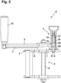
- FIG 5 shows the jig E from FIG 1 in their locked state, the locking mechanism V being in its second locking stage.
- the locking pin 1C engages in one of the locking bores G of the clasp S in the second locking stage of the locking mechanism V, the locking pin 1C is now positioned such that the nose N of the clamping lever 9 can grip between the two position rings PR of the locking pin 1C.
- the locking bolt 1C is locked by one of its two position rings PR, here the lower position ring PR according to the drawing, and the nose N of the clamping lever 9 against being pulled out (unlocking the clamping device).
- the locking mechanism V is secured in the second locking stage.
- the locking pin 1C is fixed in the second locking stage in this way.
- FIG 5 the second locking stage of the locking mechanism V is shown in the secured state.
- Unlocking the locking pin 1C i. H. Unlocking the clamping device E is only possible by the user after a predefined sequence. In this way, accidental unlocking can be avoided. In particular, accidental or unintentional unlocking is excluded.
- Unlocking the locking pin 1C ie unlocking the tensioning device E, is based on the second locking stage in the locked state ( FIG 5 ) possible by means of a two-hand forced release:
- the nose N of the clamping lever 9 is disengaged again to such an extent that the locking pin 1C can be pulled out of the clasp S by hand without hindrance.
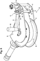
- FIG 6 shows schematically a tensioning system A with the tensioning device E designed as a belt tensioning device FIG 1 .
- the clamping system A is shown in three dimensions.
- a belt C is inserted into the tensioning system A, and thus also into the tensioning device E.
- the clamping system A in this example is a stationary, fixed and 180 ° rotatable clamping system A.
- the clasp S is designed as a rotatable clasp S in this example.
- the tensioning system A comprises an automatic belt retractor B.
- the clasp S is used to fasten the roller for the automatic belt retractor B. This means that the automatic belt retractor B is fastened in the clasp S.
- a pretensioned torsion spring (not shown) is located in the interior of the belt retraction B.
- the torsion spring is further tensioned when the belt C is pulled out.
- the tensioning device E is released, the torsion spring winds the belt C back onto the roller of the belt retraction B.
- the tensioning device E is responsible for the actual tensioning and securing of the belt C.
- the belt C rests at least on the rotating element 5 of the tensioning device E.
- the belt C is passed through the rotating element 5.
- the belt C is passed between the two rod-shaped elements D of the rotary element 5, which are designed as bolts.
- the crank 12 of the clamping device E By turning the crank 12 of the clamping device E, the The force exerted by the user is transmitted to the coupling 1 of the clamping device E, so that the rotary element 5 connected to the coupling 1 is rotated. Due to the rotary movement, the belt C is wound up by the rotary element 5, in particular by the rod-shaped elements D of the rotary element 5. That is, by turning the crank 12 of the tensioning device E, the belt C is wound up.
- the winding of the belt C leads to the force-dependent locking of the tensioning device E to a continuous tightening of the belt C, i. H. for tensioning the belt C.
- the force-dependent tensioning device E designed as a belt tensioning device, can also be used in systems other than the tensioning system A just described. Possible examples of such systems are stationary and temporary safety barriers, load securing systems integrated in vehicles and / or loose tensioning systems without belt retraction.
- the clamping device E can also be used in a clamping system in an area with high safety requirements, such as. B. for personal security.
Landscapes
- Engineering & Computer Science (AREA)
- Transportation (AREA)
- Mechanical Engineering (AREA)
- Clamps And Clips (AREA)
- Devices For Conveying Motion By Means Of Endless Flexible Members (AREA)
Description
- Die Erfindung betrifft eine Spannvorrichtung für Bänder, insbesondere für Gurte. Insbesondere betrifft die Erfindung eine kraftabhängige Gurtspannvorrichtung.
- Gurtspannsysteme mit einer Spannvorrichtung für Gurte werden hauptsächlich zur Ladungssicherung oder als wiederverwertbare temporäre Befestigungen von Maschinen, Paletten oder Ähnlichem verwendet.
- Die meisten heutzutage sich am Markt befindlichen Spannsysteme basieren auf der Grundlage, dass ein an mindestens 2 stationären Fixpunkten fest verankertes Gurtband mittels eines mechanischen Wickelsystems die Bandlänge über einen Mitnahme-Mechanismus etappenweise verkürzt und gleichzeitig gegen Zurückziehen gesichert wird. Dabei erhöht sich beim Erreichen eines Widerstandes die Spannung des Gurtbandes kontinuierlich. Diese Methode hat sich in der Praxis als zweckmäßig erwiesen.
- Die Nachteile dieser Spannsysteme bestehen aber darin, dass grundsätzlich keine Möglichkeit besteht, eine geforderte oder erwünschte Spannung des Gurtbandes anzustreben oder sogar garantieren zu können.
- Die Spannkraft dieser Spannsysteme ist grundsätzlich immer vom individuellen Kraftaufwand der Person abhängig, die den Spannvorgang durchführt.
- Aus diesem Grund besteht immer die Möglichkeit, ein Gurtband zu viel oder zu wenig als angestrebt oder vorgeschrieben zu spannen.
-
US 2008/0201922 A1 betrifft ein Verzurrgerät mit einem Handgriff, der zwischen zwei Seitenplatten angeordnet ist. Die Seitenplatten werden von ersten und zweiten Verbindungsstücken gebildet. Die ersten Verbindungsstücke sind fest mit dem Handgriff verbunden, während die zweiten Verbindungsstücke mit einer Spule zum Aufwickeln eines Bandes verdrehfest verbunden sind. Um den Spannstift ist eine Feder gewickelt, deren Enden an Querstreben zwischen den zwei Seitenplatten fixiert sind. Wenn eine zum Festzurren des Bands ausgeübte Kraft beim Betätigen des Handgriffs eine durch die Feder ausgeübte elastische Kraft erreicht oder überschreitet, knicken die ersten und zweiten Verbindungsstücke der beiden Seitenplatten gegeneinander ab. Dies zeigt einem Benutzer an, dass die mit dem Verzurrgerät ausgeübte Spannkraft ausreichend ist. - Alternativ kann eine Kontrolle der tatsächlich erzielten Gurtspannung nachträglich mit eigens dafür konzipierten Messwerkzeugen überprüft werden.
- Der Erfindung liegt die Aufgabe zugrunde, eine verbesserte Spannvorrichtung für Bänder, insbesondere für Gurte, zur Verfügung zu stellen.
- Die Aufgabe wird gelöst durch eine Spannvorrichtung gemäß Anspruch 1 für Bänder, insbesondere für Gurte, welche ein dynamisch wirkendes Element aufweist, mittels welchem eine Kraftübertragung bei der Spannvorrichtung indirekt erfolgt.
- Das heißt, dass das dynamisch wirkende Element zur indirekten Kraftübertragung eingerichtet ist.
- Bei der Kraftübertagung wird vorzugsweise eine von einem Anwender erzeugte Kraft übertragen.
- Bei einer indirekten Kraftübertragung wird zweckmäßigerweise die erzeugte Kraft des Anwenders nicht direkt - beispielsweise über einen Spannhebel - in die Spannvorrichtung eingeleitet. Zweckmäßigerweise erfolgt die Kraftübertragung des Anwenders - in Bezug auf den Spannhebel - nämlich indirekt (d. h., nicht über den Spannhebel, sondern) über ein dynamisch wirkendes Element.
- Das heißt, als Kraft übertragendes Glied dient (in diesem Fall nicht der Spannhebel, sondern) das dynamisch wirkende Element. Mit der Spannvorrichtung kann so ein System geschaffen werden, dass sich beim Erreichen der mindestens geforderten Spannkraft eines Bandes, insbesondere eines Gurtes, vorzugsweise automatisch sperrt und zugleich ein weiteres Spannen (Überspannen) verhindert.
- Insbesondere können außerdem alle Vorteile einer herkömmlichen Spannvorrichtung genutzt werden.
- Es ist vorteilhaft, wenn die Spannvorrichtung eine Kupplung aufweist. Zweckmäßigerweise ist die Spannvorrichtung dazu eingerichtet, eine Kraft indirekt über das dynamisch wirkende Element auf die Kupplung zu übertragen.
- Weiter ist es vorteilhaft, wenn die Spannvorrichtung ein mit der Kupplung verbundenes Drehelement aufweist. Zweckmäßigerweise ist die Spannvorrichtung dazu eingerichtet, eine Kraft indirekt über das dynamisch wirkende Element auf die Kupplung zu übertragen, sodass das Drehelement, insbesondere zum Spannen eines Bandes, gedreht wird.
- Es ist bevorzugt, wenn das Drehelement zumindest ein stabförmiges Element aufweist. Das stabförmige Element kann beispielsweise ein Bolzen, insbesondere ein Verbindungsbolzen, sein. Beispielsweise kann das Drehelement zwei stabförmige Elemente, insbesondere Bolzen, aufweisen.
- Vorzugsweise sind die stabförmigen Elemente des Drehelements umeinander drehbar. Prinzipiell kann das Drehelement auch anders ausgebildet sein.
- Es ist zweckmäßig, wenn das dynamisch wirkende Element unter der Kraftübertragung verbiegbar und/oder verdrehbar ist.
- Das heißt, als Kraft übertragendes Glied dient das dynamisch wirkende Element, welches "dynamisch wirkend" sich zweckmäßigerweise bei Kraftübertragung beispielsweise verbiegt ("Biegeelement") und/oder verdreht ("Torsionselement").
- Insbesondere kann das dynamisch wirkende Element eine kraftabhängige Verbiegung und/oder Verdrehung aufweisen. Das heißt, dass das dynamisch wirkende Element in Abhängigkeit der auf das Element wirkenden Kraft verbogen und/oder verdreht sein kann. Insbesondere kann der Grad der Verbiegung und/oder Verdrehung abhängig von der auf das Element wirkenden Kraft sein.
- Die Spannvorrichtung weist erfindungsgemäß einen Verriegelungsmechanismus auf.
- Der Verriegelungsmechanismus ist dazu eingerichtet, in Abhängigkeit der mittels des dynamisch wirkenden Elements übertragenen Kraft die Spannvorrichtung zu verriegeln. Das heißt, dass der Verriegelungsmechanismus vorzugsweise kraftabhängig wirkt.
- Insbesondere kann der Verriegelungsmechanismus dazu eingerichtet sein, bei einer vorgegebenen mittels des dynamisch wirkenden Elements übertragenen Kraft die Spannvorrichtung zu verriegeln.
- Beispielsweise kann der Verriegelungsmechanismus dazu eingerichtet sein, bei einer vorgegebenen Verbiegung und/oder Verdrehung des dynamisch wirkenden Elements die Spannvorrichtung zu verriegeln.
- Auf diese Weise kann die durch das Verbiegen/Verdrehen des dynamisch wirkenden Elementes in Bezug zur Spannvorrichtung entstehende geometrische Differenz ab einem vorgegebenen Wert zur automatischen Verriegelung der Spannvorrichtung führen.
- Mit der Spannvorrichtung kann so ein System geschaffen werden, dass sich beim Erreichen der mindestens geforderten Spannkraft eines Bandes, insbesondere eines Gurtes, automatisch sperrt und zugleich ein weiteres Spannen (Überspannen) verhindert. Insbesondere kann sich die Spannvorrichtung beim Erreichen der angestrebten Gurtspannung unabhängig vom Anwender selbständig verriegeln.
- Weiter kann mit der Spannvorrichtung ein selbständiges Zurückdrehen der Spannvorrichtung unter Last mechanisch verhindert und die erzielte Spannkraft des Bandes bzw. des Gurtes dauerhaft gewährleistet werden.
- Es ist vorteilhaft, wenn die Spannvorrichtung dazu eingerichtet ist, dass die Kraftübertragung bis zur Verriegelung der Spannvorrichtung mittels des dynamisch wirkenden Elements, d. h. indirekt, erfolgt. Das heißt, dass vorzugsweise die Kraftübertragung bis zur Verriegelung der Spannvorrichtung mittels des dynamisch wirkenden Elements, d. h. indirekt, erfolgt.
- In einer vorteilhaften Ausgestaltung der Erfindung umfasst der Verriegelungsmechanismus zur Verriegelung der Spannvorrichtung eine Verriegelungsstufe, die zur formschlüssigen Sperrung der Spannvorrichtung eingerichtet ist. Das heißt, vorzugsweise ist diese Verriegelungsstufe dazu eingerichtet, die Spannvorrichtung formschlüssig zu sperren.
- Auf diese Weise kann ein unbeabsichtigtes oder versehentliches Lösen der Spannvorrichtung vermieden/verhindert werden. Weiter kann auf diese Weise ein Lösen und/oder Weiterspannen durch den Anwender formschlüssig verhindert werden.
- Zweckmäßigerweise umfasst die Spannvorrichtung einen Spannhebel.
- Der Spannhebel befindet sich vorzugsweise bei der indirekten Kraftübertragung mittels des dynamisch wirkenden Elements im Leerlauf. Ein Spannhebel, der sich im Leerlauf befindet, überträgt zweckmäßigerweise keine Kraft. Vorzugsweise ist der Spannhebel im Leerlauf drehbar um die Kupplung gelagert, ohne eine Kraft - insbesondere auf die Kupplung - zu übertragen.
- Auf diese Weise kann eine indirekte Kraftübertragung gewährleistet werden.
- Der Spannhebel befindet sich vorzugsweise bis zur Verriegelung der Spannvorrichtung im Leerlauf. Das heißt, dass der Spannhebel vorzugsweise bis zur Verriegelung der Spannvorrichtung keine Kraft überträgt.
- Auf diese Weise kann ermöglicht werden, dass die Kraftübertragung bis zur Verriegelung der Spannvorrichtung nur über das dynamisch wirkende Element, d. h. indirekt, erfolgt.
- In einer bevorzugten Ausgestaltung der Erfindung umfasst der Verriegelungsmechanismus zur Verriegelung der Spannvorrichtung zwei Verriegelungsstufen. Eine der zwei Verriegelungsstufen kann die zuvor genannte Verriegelungsstufe sein.
- Vorzugsweise ist der Spannhebel zur formschlüssigen Kraftübertragung zwischen den beiden Verriegelungsstufen des Verriegelungsmechanismus eingerichtet. Das heißt, dass der Spannhebel vorzugsweise dazu eingerichtet ist, zwischen den beiden Verriegelungsstufen unter Formschluss eine Kraft - insbesondere auf die Kupplung - zu übertragen. Die (formschlüssige) Kraftübertragung mittels des Spannhebels kann als direkte Kraftübertragung aufgefasst werden.
- Das dynamisch wirkende Element kann beispielsweise ein Federstab sein. Weiter kann das dynamisch wirkende Element eine Schenkelfeder sein. Ferner kann das dynamisch wirkende Element eine Drehfeder sein. Außerdem kann das dynamisch wirkende Element beispielsweise ein Torsionselement sein.
- Ferner ist die Erfindung gerichtet auf eine Verwendung der zuvor genannten Spannvorrichtung und/oder eine seiner Weiterbildungen zum Spannen eines Bandes, insbesondere eines Gurtes.
- Vorzugsweise wird oder ist ein Band derart in die Spannvorrichtung eingelegt, dass das Band zumindest an einem Drehelement der Spannvorrichtung anliegt. Beispielsweise kann das Band derart in die Spannvorrichtung eingelegt werden/sein, dass das Band durch das Drehelement der Spannvorrichtung hindurch geführt wird/ist.
- Das im Zusammenhang mit der Verwendung genannte Drehelement ist vorzugsweise das zuvor genannte Drehelement der Spannvorrichtung.
- Weiter ist es bevorzugt, wenn eine Kraft indirekt über das dynamisch wirkende Element auf eine Kupplung der Spannvorrichtung übertragen wird, sodass das mit der Kupplung verbundene Drehelement gedreht wird, wobei das Band bei der Drehbewegung des Drehelements gespannt wird.
- Es ist bevorzugt, wenn die im Zusammenhang mit der Verwendung genannte Kupplung die zuvor genannte Kupplung ist. Weiter ist es bevorzugt, wenn das im Zusammenhang mit der Verwendung genannte Drehelement das zuvor genannte Drehelement ist. Vorzugsweise wird das dynamisch wirkende Element in Abhängigkeit der auf das Element wirkenden Kraft verbogen und/oder verdreht.
- Weiter ist es bevorzugt, wenn die Spannvorrichtung bei einer vorgegebenen Verbiegung und/oder Verdrehung des dynamisch wirkenden Elements verriegelt wird.
- Auch wenn in der Beschreibung bzw. in den Patentansprüchen einige Begriffe jeweils im Singular oder in Verbindung mit einem Zahlwort verwendet werden, soll der Umfang der Erfindung für diese Begriffe nicht auf den Singular oder das jeweilige Zahlwort eingeschränkt sein.
- Die oben beschriebenen Eigenschaften, Merkmale und Vorteile dieser Erfindung sowie die Art und Weise, wie diese erreicht werden, werden klarer und deutlicher verständlich im Zusammenhang mit der folgenden Beschreibung der Ausführungsbeispiele, die im Zusammenhang mit den Zeichnungen näher erläutert werden. Die Ausführungsbeispiele dienen der Erläuterung der Erfindung und beschränken die Erfindung nicht auf die darin angegebene Kombination von Merkmalen, auch nicht in Bezug auf funktionale Merkmale.
- Es zeigen:
- FIG 1
- eine Spannvorrichtung für Bänder in ihren entriegelten Zustand,
- FIG 2
- die Kupplung und den Sperrbolzen der Spannvorrichtung aus
FIG 1 , - FIG 3
- den Spannhebel und das dynamisch wirkende Element der Spannvorrichtung aus
FIG 1 in einem unbelasteten Zustand, - FIG 4
- den Spannhebel und das dynamisch wirkende Element aus
FIG 3 im Zustand der maximalen Kraftübertragung, - FIG 5
- die Spannvorrichtung aus
FIG 1 in ihrem verriegelten Zustand und - FIG 6
- ein Spannsystem mit der Spannvorrichtung aus
FIG 1 , wobei ein Gurt in das Spannsystem eingelegt ist. -
FIG 1 zeigt schematisch eine Spannvorrichtung E für Bänder in einer Schnittdarstellung. Die Spannvorrichtung E ist in diesem Beispiel als Spannvorrichtung E für einen Gurt, kurz Gurtspannvorrichtung, ausgebildet. Die Spannvorrichtung kann auch zum Spannen eines beliebigen Bandes (anstatt des hier als Gurt, auch Gurtband, ausgebildeten Bandes) geeignet sein. - Die Spannvorrichtung E umfasst eine Kupplung 1 und ein mit der Kupplung 1 verbundenes Drehelement 5. Das Drehelement 5 weist in diesem Beispiel zwei stabförmige Elemente D auf. Die stabförmigen Elemente D sind in diesem Beispiel als Bolzen, insbesondere als Verbindungsbolzen, ausbildet. Die zwei stabförmigen Elemente D sind umeinander drehbar. Das Drehelement 5 kann prinzipiell auch anders ausgeführt sein.
- Die Kupplung 1 und das Drehelement 5 sind in eine Spange S der Spannvorrichtung E eingesetzt.
- Wird eine Kraft auf die Kupplung 1 übertragen, dann wird (unter bestimmten Bedingungen, insbesondere bei ausreichender Kraft) das Drehelement 5 gedreht. Unter Verwendung der Drehbewegung kann ein zumindest an dem Drehelement 5 anliegender Gurt, insbesondere ein durch das Drehelement 5 hindurchgeführter Gurt, (nicht gezeigt, vgl.
FIG 6 ) gespannt werden. Das heißt, dass aufgrund der Drehbewegung des Drehelements 5 ein Gurt gespannt werden kann. Die Drehbewegung des Drehelements 5 ist eine Drehbewegung um die eigene Achse, d. h. eine Rotation um die eigene Achse. - Wird das Drehelement 5 gedreht, so wird es gegenüber der Spange S gedreht. Das heißt, dass die Drehbewegung des Drehelements 5 eine Drehbewegung gegenüber der Spange S ist.
- Wird das Drehelement 5 gedreht, so werden in diesem Beispiel die als Bolzen ausgeführten stabförmigen Elemente D umeinander gedreht. Aufgrund der Drehbewegung des Drehelements 5 kann der zuvor genannte Gurt um die als Bolzen ausgeführten stabförmigen Elemente D gewickelt werden.
- Weiter umfasst die Spannvorrichtung E ein dynamisch wirkendes Element 2. Mittels des dynamisch wirkenden Elements 2 erfolgt die Kraftübertragung bei der Spannvorrichtung E indirekt.
- Insbesondere ist die Spannvorrichtung E dazu eingerichtet, die Kraft indirekt über das dynamisch wirkende Element 2 auf die Kupplung 1 zu übertragen, sodass das Drehelement 5 zum Spannen eines Gurts gedreht wird.
- Das heißt, wenn von einem Anwender eine Kraft ausgeübt wird, dann wird diese Kraft indirekt über das dynamisch wirkende Element 2 auf die Kupplung 1 übertragen.
- Das dynamisch wirkende Element 2 ist in diesem Ausführungsbeispiel ein Federstab. Das dynamisch wirkende Element 2 könnte auch eine Schenkelfeder, eine Drehfeder, ein Torsionselement o. Ä. sein.
- Das dynamisch wirkende Element 2 ist in diesem Beispiel unter der Kraftübertragung verbiegbar. Prinzipiell könnte das dynamisch wirkende Element 2 auch verdrehbar sein.
- Insbesondere weist das dynamisch wirkende Element 2 eine kraftabhängige Verbiegung auf.
- Überträgt das dynamisch wirkende Element 2 keine Kraft, dann ist es nicht verbogen, d. h. seine Verbiegung beträgt Null. Je höher die Kraft ist, die das dynamisch wirkende Element 2 überträgt, desto mehr ist das dynamisch wirkende Element 2 verbogen, d. h. desto höher ist die Verbiegung.
- Die Spannvorrichtung E umfasst einen Spannhebel 9. Bei der indirekten Kraftübertragung mittels des dynamisch wirkenden Elements 2 befindet sich der Spannhebel 9 im Leerlauf.
- Im Leerlauf ist der Spannhebel 9 nicht mit der Kupplung 1 gekuppelt. Insbesondere ist der Spannhebel 9 im Leerlauf drehbar um die Kupplung 1 gelagert, ohne eine Kraft auf die Kupplung 1 zu übertragen. Auf diese Weise kann eine indirekte Kraftübertragung mittels des dynamisch wirkenden Elements 2 gewährleistet werden. Weiter kann auf diese Weise eine direkte Kraftübertragung mittels des Spannhebels 9 vermieden werden.
- Außerdem umfasst die Spannvorrichtung E eine Kurbel 12. Der Anwender kann Kraft auf die Kurbel 12 ausüben. Insbesondere kann der Anwender die Kurbel 12 um die Kupplung 1 drehen.
- Die Kurbel 12 ist mit dem dynamisch wirkenden Element 2 verbunden. Außerdem ist die Kurbel 12 mit dem Spannhebel 9 verbunden. Die Kurbel 12 könnte prinzipiell auch als Teil des Spannhebels 9 aufgefasst werden.
- Mittels der Kurbel 12 kann eine vom Anwender ausgeübte Kraft auf das dynamisch wirkende Element 2 und auf den Spannhebel 9 übertragen werden.
- Die Spannvorrichtung E umfasst außerdem einen Verriegelungsmechanismus V. Mittels des Verriegelungsmechanismus V kann die Spannvorrichtung E von einem entriegelten, d. h. entsperrten, Zustand in einen verriegelten Zustand gebracht werden ("Verriegelung"). Weiter kann die Spannvorrichtung E mittels des Verriegelungsmechanismus V von dem verriegelten Zustand in den entriegelten Zustand gebracht werden ("Entriegelung").
- Die Verrieglung erfolgt automatisch/selbstständig, insbesondere ohne manuelle Betätigung des Verriegelungsmechanismus V. Die Entriegelung erfolgt manuell.
- Der Verriegelungsmechanismus V ist dazu eingerichtet, in Abhängigkeit der mittels des dynamisch wirkenden Elements 2 übertragenen Kraft die Spannvorrichtung E zu verriegeln. Das heißt, dass der Verriegelungsmechanismus V kraftabhängig wirkt. Insbesondere ist der Verriegelungsmechanismus V dazu eingerichtet, bei einer vorgegebenen Verbiegung des dynamisch wirkenden Elements 2 die Spannvorrichtung E zu verriegeln.
- Wenn die mittels des dynamisch wirkenden Elements 2 übertragene Kraft einen vorgegebenen Wert annimmt, dann entspricht die Verbiegung des dynamisch wirkenden Elements 2 der vorgegebenen Verbiegung, und dann verriegelt der Verriegelungsmechanismus V die Spannvorrichtung E.
- Der Verriegelungspunkt (d. h. die anzuwendende Kraft bzw. die vorgegebene Verbiegung, bei der der Verriegelungsmechanismus V verriegelt) kann konstruktiv vorgegeben sein und/oder mechanisch einstellbar sein.
- Der Verriegelungsmechanismus V umfasst einen Sperrbolzen 1C und eine Druckfeder 1B. In diesem Ausführungsbeispiel umfasst der Verriegelungsmechanismus V zwei Verriegelungsstufen (vgl.
FIG 4 undFIG 5 ). Unter Verwendung der Verriegelungsstufen findet die Verriegelung stufenweise statt. - Die Kupplung 1 weist ein Führungsrohr 1A auf. In dem Führungsrohr 1A der Kupplung 1 befindet sich der Sperrbolzen 1C. Der Sperrbolzen 1C wird durch die Druckfeder 1B in Richtung der Spange S bzw. gegen die Spange S der Spannvorrichtung E gedrückt. Der Sperrbolzen 1C weist zumindest einen, hier zwei, Positionsring(e) PR auf.
-
FIG 2 zeigt die Kupplung 1 und den Sperrbolzen 1C ausFIG 1 in einer dreidimensionalen Ansicht. - Das Führungsrohr 1A weist eine Aussparung 1D auf (vgl.
FIG 1 ,FIG 2 ) . - Der Spannhebel 9 weist eine Nase N auf (vgl.
FIG 1 ,FIG 3 ). Der Spannhebel 9 weist außerdem seitlich angeordnete Mitnahmeklauen M auf (vgl.FIG 3 ). - Ferner weist die Spange S zumindest eine, hier mehrere, Arretierungsbohrung(en) G auf.
- In
FIG 1 ist der entriegelte Zustand des Verriegelungsmechanismus V gezeigt. Das heißt, inFIG 2 ist die Spannvorrichtung entriegelt:
Die Nase N des Spannhebels 9 ragt in die Aussparung 1D des Führungsrohrs 1A hinein. - Im entriegelten, d. h. entsperrten, Zustand wird der Sperrbolzen 1C an einem seiner zwei Positionsringe PR durch die Nase N des Spannhebels 9 im gezogenen (entsperrten) Zustand gehalten.
- Insbesondere liegt im entriegelten Zustand einer der Positionsringe PR des Sperrbolzens 1C, hier der zeichnungsgemäß untere Positionsring PR, an der Nase N des Spannhebels 9 an und wird gegen diese Nase N gedrückt. Das heißt, die Nase N des Spannhebels 9 ragt derart in die Aussparung 1D des Führungsrohrs 1A hinein, dass einer der Positionsringe PR, hier der untere Positionsring PR, des Sperrbolzens 1C gegen die Nase N gedrückt wird.
- Auf diese Weise kann ein Einrasten des Sperrbolzens 1C in die Spange S und somit ein Verriegeln verhindert werden.
- Die Kraftübertragung erfolgt bei der Spannvorrichtung E im entriegelten Zustand, d. h. bis zur Verriegelung der Spannvorrichtung E, mittels des dynamisch wirkenden Elements 2.
- In die Spannvorrichtung E kann ein Gurt C eingelegt werden. Insbesondere kann der Gurt C derart in die Spannvorrichtung E eingelegt werden, dass der Gurt C zumindest an dem Drehelement 5 der Spannvorrichtung E anliegt (nicht gezeigt, vgl.
FIG 6 ). Beispielsweise kann der Gurt C derart in die Spannvorrichtung E eingelegt werden, dass der Gurt C durch das Drehelement 5, insbesondere zwischen den beiden stabförmigen Elementen D des Drehelements 5, hindurchgeführt wird. - In
FIG 1 ist außerdem eine Schnittebene III - III eingezeichnet. -
FIG 3 zeigt den Spannhebel 9 und die Kupplung 1 ausFIG 1 als Schnittdarstellung entlang der Schnittebene III - III. Obwohl das dynamisch wirkende Element 2 von dem Spannhebel 9 verdeckt ist, ist seine Stellung inFIG 3 angedeutet. - Der Spannhebel 9 und das dynamisch wirkende Element 2 befinden sich in einem unbelasteten Zustand ohne Kraftübertragung (Zustand "F0").
- Da das dynamisch wirkende Element 2 keine Kraft überträgt, wird es nicht verbogen, d. h. seine Verbiegung beträgt Null. Das dynamische Element 2 ist also in seinem Ausgangszustand. Der Spannhebel 9 ist ohne Formschluss und ohne Kraftschluss um das Zentrum der Kupplung 1 drehbar gelagert. Insbesondere sind die Mitnahmeklauen M des Spannhebels 9 beabstandet zu dem Führungsrohr 1A angeordnet.
- Insbesondere ist der Spannhebel 9 bis zum Anschlagen an einer der beiden Mitnahmeklauen M ohne Form- oder Kraftschluss um das Zentrum der Kupplung 1 drehbar gelagert.
- Ausgehend vom entsperrten Zustand in
FIG 1 hält das dynamisch wirkende Element 2 im unbelasteten Zustand F0 den Spannhebel 9 in der Mitte der Kupplung 1 (sieheFIG 3 ) und die Nase N fixiert dabei den Sperrbolzen 1C ("entsperrter Zustand", vgl.FIG 1 ). - Wenn ausgehend von dem unbelasteten Zustand F0 (
FIG 3 ) ein Anwender an der Kurbel 12 dreht, so übt er eine Kraft auf die Kurbel 12 aus. Die vom Anwender ausgeübte Kraft wird auf das dynamisch wirkende Element 2 und auf den Spannhebel 9 übertragen. Auf diese Weise werden sowohl das dynamisch wirkende Element 2 als auch der Spannhebel 9 um die Kupplung herum gedreht. - Da sich der Spannhebel im Leerlauf befindet, überträgt der Spannhebel keine Kraft auf die Kupplung 1. Die vom Anwender ausgeübte Kraft wird über das als Federstab ausgebildete dynamisch wirkende Element 2, d. h. indirekt, auf die Kupplung 1 übertragen. Die Kupplung 1 sowie ihr Führungsrohr 1A werden auf diese Weise gedreht.
- Ist ein Gurt C in die Spannvorrichtung E eingelegt, dann beginnt sich der Gurt C zu spannen.
- Die Kraft wird indirekt über das dynamisch wirkende Element 2 auf die Kupplung 1 der Spannvorrichtung E übertragen, sodass das mit der Kupplung 1 verbundene Drehelement 5 gedreht wird. Das Band C wird bei der Drehbewegung des Drehelements 5 gespannt.
- Bei zunehmender Spannung des Gurtes C muss der Anwender die angewendete Kraft steigern. Da bei zunehmender Spannung des Gurtes C die vom Anwender erzeugte Kraft steigt, steigt auch die durch das als Federstab ausgeführte dynamisch wirkende Element 2 übertragene Kraft. Dieses führt zur einer kontinuierlichen kraftabhängigen Verbiegung des als Federstab ausgeführten dynamisch wirkenden Elements 2. Das heißt, dass das dynamisch wirkende Element 2 in Abhängigkeit der auf das Element 2 wirkenden Kraft verbogen wird.
- Je höher die Kraft ist, die das dynamisch wirkende Element 2 überträgt, desto mehr wird das dynamisch wirkende Element 2 verbogen, d. h. desto höher ist die Verbiegung.
- Beim Erreichen des konstruktiv vorgegebenen Maximal-Biegewinkels, d. h. beim Erreichen der konstruktiv vorgegebenen maximalen Verbiegung, ist die maximal durch das als Federstab ausgeführte dynamisch wirkende Element 2 übertragbare Kraft erreicht (Zustand "F+"). Somit ist eine mit dem Zustand F+ zusammenhängende minimal angestrebte Gurtspannung erreicht.
- In
FIG 4 ist der Spannhebel 9 und die Kupplung 1 ausFIG 3 im Zustand der maximalen Kraftübertragung (Zustand F+) dargestellt. Auch die Stellung des dynamisch wirkenden Elements 2 im Zustand F+ ist inFIG 4 sichtbar. Zum Vergleich ist inFIG 4 außerdem die Stellung des dynamisch wirkenden Elements 2 im Zustand F0 gestrichelt angedeutet. - Die Spannvorrichtung E wird bei einer vorgegebenen Verbiegung des dynamisch wirkenden Elements 2, nämlich beim Erreichen des konstruktiv vorgegebenen Maximal-Biegewinkels (Zustand "F+"), verriegelt. Hier erfolgt die Verrieglung stufenweise in zwei Verriegelungsstufen.
- Beim Erreichen des Zustands F+ wird die erste Verriegelungsstufe erreicht.
- Im Zustand F+, d. h. beim Erreichen der minimal angestrebten Gurtspannung im Punkt F+, ist der Spannhebel 9 so weit ausgerückt, dass die Nase N des Spannhebels 9 den zeichnungsgemäß unteren Positionsring PR des Sperrbolzens 1C freigibt und der Sperrbolzen 1C durch die Druckfeder 1B gegen die Spange S gedrückt wird.
- Wenn der Sperrbolzen 1C gegen die Spange S gedrückt wird, dann befindet sich der Verrieglungsmechanismus V in seiner ersten Verriegelungsstufe.
- In der Regel ist beim Erreichen des Zustands F+ keine Arretierungsbohrung G derart positioniert, dass der Sperrbolzen 1C direkt in diese Arretierungsbohrung G eingreifen/einrasten könnte.
- Im Zustand F+ ist der Spannhebel 9 derart positioniert, dass eine der Mitnahmeklauen M an dem Führungsrohr 1A anschlägt. Auf diese Weise ist im Zustand F+ der Spannhebel 9 derart positioniert, dass der Spannhebel 9 eine formschlüssige Kraftübertragung herstellt.
- Die im Zustand F+ von einem Anwender ausgeübte Kraft wird direkt über den Spannhebel 9 formschlüssig auf die Kupplung 1 übertragen. Insbesondere wird im Zustand F+ die von einem Anwender ausgeübte Kraft über die an dem Führungsrohr 1A anschlagende Mitnahmeklauen M des Spannhebels 9 auf das Führungsrohr 1A der Kupplung 1 übertragen.
- Ausgehend vom Zustand F+ (
FIG 4 ) bewirkt die vom Anwender ausgeübte Kraft ein Drehen des Drehelements D, sodass ein in die Spannvorrichtung E eingelegtes Band C weiter gespannt werden kann. - Ausgehend vom Zustand F+ (
FIG 4 ), d. h. nach dem Erreichen des Punktes F+, erfolgt ein noch weiteres Spannen des Gurtes mit formschlüssiger Kraftübertragung über die Mitnahmeklaue M solange, bis der Sperrbolzen 1C in eine der Arretierungsbohrungen G an der Spange S einrastet. Auf diese Weise wird eine formschlüssige Sperrung der Spannvorrichtung E erreicht. - Aufgrund des weiteren Spannens des Gurtes ausgehend vom Zustand F+ liegt die maximale Gurtspannung höher als die bei dem Punkt F+ erreichte Gurtspannung.
- Der angestrebte Gurtspannungsbereich kann konstruktiv beeinflusst werden z. B. durch einen Durchmesser des Federstabes, eine Länge des Federstabes und/oder eine Einteilung der Arretierungsbohrungen G (geringerer Lochabstand ergibt einen geringeren Toleranzbereich zwischen minimaler und maximaler Gurtspannung). Weiter kann die Länge des Federstabes durch den Anwender einstellbar sein, was einen individuell wählbaren Gurtspannungsbereich ermöglicht.
- Wenn der Sperrbolzen 1C in eine der Arretierungsbohrungen G an der Spange S einrastet, dann ist die zweite Verriegelungsstufe erreicht. Das heißt, dass in der zweite Verriegelungsstufe die Spannvorrichtung E formschlüssig gesperrt ist.
- Durch das Einrasten des Sperrbolzen 1C in der Spange S ist eine formschlüssige Verbindung zwischen der Kupplung 1 und der Spange S entstanden. Ein weiteres Spannen durch den Anwender ist nun nicht mehr möglich.
- Falls beim Erreichen des Zustands F+ eine der Arretierungsbohrungen G derart positioniert ist, dass der Sperrbolzen 1C direkt in diese Arretierungsbohrung G eingreifen/einrasten kann, so kann der Verriegelungsmechanismus V direkt von der ersten Verriegelungsstufe in die zweite Verriegelungsstufe übergehen, ohne dass ein weiteres Spannen des Gurtes C nötig ist.
-
FIG 5 zeigt die Spannvorrichtung E ausFIG 1 in ihrem verriegelten Zustand, wobei sich der Verriegelungsmechanismus V in seiner zweiten Verriegelungsstufe befindet. - Nach Beendigung des Spannvorgangs endet die Krafteinleitung durch den Anwender, und das als Federstab ausgebildete dynamisch wirkende Element 2 stellt aufgrund seiner Federwirkung den Spannhebel 9 von der Stellung des Punktes F+ (
FIG 4 ) zurück auf die ursprüngliche Stellung an Punkt F0 (vgl.FIG 3 ). - Da der Sperrbolzen 1C in der zweiten Verriegelungsstufe des Verriegelungsmechanismus V in eine der Arretierungsbohrungen G der Spange S eingreift, ist der Sperrbolzen 1C nun derart positioniert, dass die Nase N des Spannhebels 9 zwischen den beiden Positionsringen PR des Sperrbolzens 1C greifen kann.
- In dieser Stellung wird der Sperrbolzen 1C durch einen seiner zwei Positionsringe PR, hier den zeichnungsgemäß unteren Positionsring PR, und der Nase N des Spannhebels 9 gegen ein Herausziehen (Entsichern der Spannvorrichtung) gesperrt.
- Auf diese Weise wird der Verrieglungsmechanismus V in der zweiten Verriegelungsstufe gesichert. Insbesondere wird auf diese Weise der Sperrbolzen 1C in der zweiten Verriegelungsstufe festgesetzt.
- In
FIG 5 ist die zweite Verriegelungsstufe des Verrieglungsmechanismus V im gesicherten Zustand dargestellt. - Ein Entsichern des Sperrbolzens 1C, d. h. ein Entsperren der Spannvorrichtung E, ist durch den Anwender nur nach einem vordefinierten Ablauf möglich. Auf diese Weise kann ein versehentliches Entsperren vermieden werden. Insbesondere ist ein zufälliges oder ungewolltes Entsichern somit ausgeschlossen.
- Ein Entsichern des Sperrbolzens 1C, d. h. ein Entsperren der Spannvorrichtung E, ist ausgehend von der zweiten Verriegelungsstufe im gesicherten Zustand (
FIG 5 ) mittels einer Zwei-Hand-Zwangs-Entsicherung möglich:
Zum Entsichern ist der Spannhebel 9 durch den Anwender mindestens auf die Stellung des Punktes F+ zu bringen. Beim Erreichen des Punktes F+ ist die Nase N des Spannhebels 9 wieder soweit ausgerückt, dass der Sperrbolzen 1C ungehindert von Hand aus der Spange S gezogen werden kann. - Beim Zurückdrehen des Spannhebels 9 mit gleichzeitig gezogenem Sperrbolzen 1C rückt die Nase N des Spannhebels 9 bedingt durch die Kraft des dynamisch wirkenden Elements 2 in ihre Grundstellung F0 zurück. Dabei wird der Sperrbolzen 1C nun wieder an einem der Positionsringe PR, hier dem unteren Positionsring PR, durch die Nase N des Spannhebels 9 im gezogenen (entsperrten) Zustand gehalten und der Gurt C kann ungehindert durch weiteres Zurückdrehen des Spannhebels 9 komplett entspannt werden.
-
FIG 6 zeigt schematisch ein Spannsystem A mit der als Gurtspannvorrichtung ausgebildeten Spannvorrichtung E ausFIG 1 . Das Spannsystem A ist dreidimensional dargestellt. In diesem Beispiel ist ein Gurt C in das Spannsystem A, und somit auch in die Spannvorrichtung E eingelegt. - Das Spannsystem A ist in diesem Beispiel ein stationär befestigtes und um 180° drehbares Spannsystem A. Die Spange S ist in diesem Beispiel als drehbare Spange S ausgeführt.
- Das Spannsystem A umfasst einen automatischem Gurteinzug B. Die Spange S dient zur Befestigung der Rolle für den automatischen Gurteinzug B. Das heißt, dass der automatische Gurteinzug B in der Spange S befestigt ist. Im Innenbereich des Gurteinzuges B befindet sich eine vorgespannte Drehfeder (nicht dargestellt).
- Die Drehfeder wird beim Herausziehen des Gurtes C zusätzlich weitergespannt. Beim Lösen der Spannvorrichtung E wickelt die Drehfeder den Gurt C wieder auf die Rolle des Gurteinzuges B auf.
- Das eigentliche Spannen und Sichern des Gurtes C übernimmt dabei die Spannvorrichtung E.
- Der Gurt C liegt zumindest an dem Drehelement 5 der Spannvorrichtung E an. In diesem Beispiel ist der Gurt C durch das Drehelement 5 hindurchgeführt. Insbesondere ist der Gurt C zwischen den beiden als Bolzen ausgeführten stabförmigen Elementen D des Drehelements 5 hindurchgeführt.
- Durch das Drehen der Kurbel 12 der Spannvorrichtung E wird die vom Anwender ausgeübte Kraft auf die Kupplung 1 der Spannvorrichtung E übertragen, sodass das mit der Kupplung 1 verbundene Drehelement 5 gedreht wird. Aufgrund der Drehbewegung wird der Gurt C von dem Drehelement 5, insbesondere von den stabförmigen Elementen D des Drehelements 5, aufgewickelt. Das heißt, durch das Drehen der Kurbel 12 der Spannvorrichtung E wird der Gurt C aufgewickelt.
- Das Aufwickeln des Gurtes C führt bis zur kraftabhängigen Arretierung der Spannvorrichtung E zu einer kontinuierlichen Straffung des Gurtes C, d. h. zu einem Spannen des Gurtes C. Die kraftabhängige als Gurtspannvorrichtung ausgebildete Spannvorrichtung E kann auch in anderen Systemen als dem eben beschriebenen Spannsystem A verwendet werden. Mögliche Beispiele für solche Systeme sind stationäre und temporäre Sicherheitsabsperrungen, in Fahrzeugen integrierte Ladungssicherungen und/oder lose Spannsysteme ohne Gurteinzug. Die Spannvorrichtung E kann auch in einem Spannsystem in einem Bereich mit hohen Sicherheitsanforderungen eingesetzt werden, wie z. B. zur Personensicherung.
- Obwohl die Erfindung im Detail durch die bevorzugten Ausführungsbeispiele näher illustriert und beschrieben wurde, so ist die Erfindung nicht durch die offenbarten Beispiele eingeschränkt und andere Variationen können vom Fachmann hieraus abgeleitet werden, ohne den Schutzumfang der Erfindung, in den Ansprüchen definiert, zu verlassen.
-
- 1
- Kupplung
- 1A
- Führungsrohr
- 1B
- Druckfeder
- 1C
- Sperrbolzen
- 1D
- Aussparung
- 2
- dynamisch wirkendes Element
- 5
- Drehelement
- 9
- Spannhebel
- 12
- Kurbel
- A
- Spannsystem
- B
- Gurteinzug
- C
- Gurt
- D
- stabförmiges Element, insbesondere Bolzen
- E
- Spannvorrichtung
- F0
- unbelasteter Zustand
- F+
- Zustand maximaler Kraftübertragung
- G
- Arretierungsbohrung
- N
- Nase
- M
- Mitnahmeklaue
- PR
- Positionsring
- S
- Spange
- V
- Verriegelungsmechanismus
Claims (14)
- Spannvorrichtung (E) für Bänder (C), insbesondere für Gurte (C), mit einem dynamisch wirkenden Element (2), mittels welchem eine Kraftübertragung bei der Spannvorrichtung (E) indirekt erfolgt,gekennzeichnet durcheinen Verriegelungsmechanismus (V), welcher dazu eingerichtet ist, in Abhängigkeit der mittels des dynamisch wirkenden Elements (2) übertragenen Kraft die Spannvorrichtung (E) zu verriegeln.
- Spannvorrichtung (E) nach einem der vorhergehenden Ansprüche,gekennzeichnet durcheine Kupplung (1) und ein mit der Kupplung (1) verbundenes Drehelement (D),wobei die Spannvorrichtung (E) dazu eingerichtet ist, eine Kraft indirekt über das dynamisch wirkende Element (2) auf die Kupplung (1) zu übertragen, sodass das Drehelement (D), insbesondere zum Spannen eines Bandes (C), gedreht wird.
- Spannvorrichtung (E) nach Anspruch 1 oder 2,dadurch gekennzeichnet,dass das dynamisch wirkende Element (2) unter der Kraftübertragung verbiegbar und/oder verdrehbar ist.
- Spannvorrichtung (E) nach einem der vorhergehenden Ansprüche,dadurch gekennzeichnet,dass das dynamisch wirkende Element (2) eine kraftabhängige Verbiegung und/oder Verdrehung aufweist.
- Spannvorrichtung (E) nach einem der vorhergehenden Ansprüche,dadurch gekennzeichnet,dass der Verriegelungsmechanismus (V) dazu eingerichtet ist, bei einer vorgegebenen Verbiegung und/oder Verdrehung des dynamisch wirkenden Elements (2) die Spannvorrichtung (E) zu verriegeln.
- Spannvorrichtung (E) nach einem der vorhergehenden Ansprüche,
welche dazu eingerichtet ist, dass die Kraftübertragung bis zur Verriegelung der Spannvorrichtung (E) mittels des dynamisch wirkenden Elements (2) erfolgt. - Spannvorrichtung (E) nach einem der vorhergehenden Ansprüche,dadurch gekennzeichnet,dass der Verriegelungsmechanismus (V) zur Verriegelung der Spannvorrichtung (E) eine Verriegelungsstufe umfasst,die zur formschlüssigen Sperrung der Spannvorrichtung (E) eingerichtet ist.
- Spannvorrichtung (E) nach einem der vorhergehenden Ansprüche,gekennzeichnet durcheinen Spannhebel (9), welcher sich bei der indirekten Kraftübertragung mittels des dynamisch wirkenden Elements (2) im Leerlauf befindet.
- Spannvorrichtung (E) nach Anspruch 8,dadurch gekennzeichnet,dass der Verriegelungsmechanismus (V) zur Verriegelung der Spannvorrichtung (E) zwei Verriegelungsstufen umfasst, und dass der Spannhebel (9) zur formschlüssigen Kraftübertragung zwischen den beiden Verriegelungsstufen des Verriegelungsmechanismus (V) eingerichtet ist.
- Spannvorrichtung (E) nach einem der vorhergehenden Ansprüche,dadurch gekennzeichnet,dass das dynamisch wirkende Element (2) ein Federstab (2) ist.
- Spannvorrichtung (E) nach einem der Ansprüche 1 bis9,dadurch gekennzeichnet,dass das dynamisch wirkende Element (2) eine Schenkelfeder ist.
- Spannvorrichtung (E) nach einem der Ansprüche 1 bis 9,dadurch gekennzeichnet,dass das dynamisch wirkende Element (2) eine Drehfeder ist.
- Spannvorrichtung (E) nach einem der Ansprüche 1 bis9,dadurch gekennzeichnet,dass das dynamisch wirkende Element (2) ein Torsionselement ist.
- Verwendung der Spannvorrichtung (E) nach einem der vorhergehenden Ansprüche zum Spannen eines Bandes (C), insbesondere eines Gurtes (C),dadurch gekennzeichnet,dass ein Band (C) derart in die Spannvorrichtung (E) eingelegt wird oder ist, dass das Band (C) zumindest an einem Drehelement (D) der Spannvorrichtung (E) anliegt,und dass eine Kraft indirekt über das dynamisch wirkende Element (2) auf eine Kupplung (1) der Spannvorrichtung (E) übertragen wird, sodass das mit der Kupplung (1) verbundene Drehelement (D) gedreht wird, wobei das Band (C) bei der Drehbewegung des Drehelements (D) gespannt wird.
Applications Claiming Priority (2)
| Application Number | Priority Date | Filing Date | Title |
|---|---|---|---|
| DE102019102914 | 2019-02-06 | ||
| DE102019110559.5A DE102019110559A1 (de) | 2019-02-06 | 2019-04-24 | Spannvorrichtung für Bänder |
Publications (2)
| Publication Number | Publication Date |
|---|---|
| EP3693216A1 EP3693216A1 (de) | 2020-08-12 |
| EP3693216B1 true EP3693216B1 (de) | 2021-10-13 |
Family
ID=69174326
Family Applications (1)
| Application Number | Title | Priority Date | Filing Date |
|---|---|---|---|
| EP20152103.6A Active EP3693216B1 (de) | 2019-02-06 | 2020-01-16 | Spannvorrichtung für bänder |
Country Status (2)
| Country | Link |
|---|---|
| EP (1) | EP3693216B1 (de) |
| ES (1) | ES2901931T3 (de) |
Family Cites Families (4)
| Publication number | Priority date | Publication date | Assignee | Title |
|---|---|---|---|---|
| CN2677298Y (zh) * | 2004-02-05 | 2005-02-09 | 玉环双友机械工具有限公司 | 捆绑器的手柄 |
| AU2007231005B2 (en) * | 2006-03-22 | 2013-01-10 | Rollin Woodruff | Winch with tension indicator |
| DE102006044024B3 (de) * | 2006-09-14 | 2008-03-27 | Braun Gmbh | Verlängerungselement für Spannratschen |
| DE102009055740B4 (de) * | 2009-11-26 | 2014-04-03 | Braun Gmbh | Verlängerungselement für Spannratschen |
-
2020
- 2020-01-16 EP EP20152103.6A patent/EP3693216B1/de active Active
- 2020-01-16 ES ES20152103T patent/ES2901931T3/es active Active
Also Published As
| Publication number | Publication date |
|---|---|
| EP3693216A1 (de) | 2020-08-12 |
| ES2901931T3 (es) | 2022-03-24 |
Similar Documents
| Publication | Publication Date | Title |
|---|---|---|
| EP0085965A1 (de) | Spannschloss für Gurtbänder | |
| DE10164638A1 (de) | Gurtkraftbegrenzer | |
| EP0281836B1 (de) | Gurtanschlussvorrichtung | |
| EP0320739B1 (de) | Vorrichtung zum Verstellen eines Gurtumlenkbeschlages für einen Sicherheitsgurt | |
| DE10122910A1 (de) | Rückhaltevorrichtung für einen Fahrzeuginsassen | |
| DE202018107429U1 (de) | Einziehbare Leine mit automatischer Ver- und Entriegelungsfunktion | |
| EP4069573B1 (de) | Vorrichtung zur neigungsverstellung eines objekts | |
| EP2065077B1 (de) | Set für die Installation einer Slackline | |
| DE102019110559A1 (de) | Spannvorrichtung für Bänder | |
| DE10015048C1 (de) | Gurtaufroller mit einer als Blechbiegebremse ausgebildeten Kraftbegrenzungseinrichtung | |
| EP3693216A1 (de) | Spannvorrichtung für bänder | |
| DE3430140A1 (de) | Gurtspannvorrichtung mit sperrung | |
| DE102011056879A1 (de) | Gurtspannvorrichtung | |
| DE29615284U1 (de) | Spannvorrichtung zum Spannen von Gurten o.dgl. | |
| DE19839245C1 (de) | Spannvorrichtung für Gurte und dergleichen | |
| DE202020000092U1 (de) | Bandförmiges Spannmittel und Schuh mit einem solchen Spannmittel | |
| DE29600777U1 (de) | Vorrichtung zum gleichzeitigen Straffen mehrerer in einem Kraftfahrzeug angeordneter Sicherheitsgurte | |
| DE3638882C2 (de) | ||
| EP2120622B1 (de) | Ratschenschnalle für einen skischuh | |
| DE102006019270A1 (de) | Sicherheitsgurtaufroller mit einem einen Verstärkungsabschnitt aufweisenden Torsionsstab | |
| DE1531548A1 (de) | Gurt-Abspannvorrichtung,insbesondere Sicherheitsgurt | |
| DE29823091U1 (de) | Spannvorrichtung für ein flexibles Zugelement einer Markise | |
| EP2759420B1 (de) | Spannelemente für Schneeketten | |
| AT509610B1 (de) | Verstellvorrichtung, insbesondere längenverstellvorrichtung | |
| AT390487B (de) | Spannvorrichtung |
Legal Events
| Date | Code | Title | Description |
|---|---|---|---|
| PUAI | Public reference made under article 153(3) epc to a published international application that has entered the european phase |
Free format text: ORIGINAL CODE: 0009012 |
|
| STAA | Information on the status of an ep patent application or granted ep patent |
Free format text: STATUS: THE APPLICATION HAS BEEN PUBLISHED |
|
| AK | Designated contracting states |
Kind code of ref document: A1 Designated state(s): AL AT BE BG CH CY CZ DE DK EE ES FI FR GB GR HR HU IE IS IT LI LT LU LV MC MK MT NL NO PL PT RO RS SE SI SK SM TR |
|
| AX | Request for extension of the european patent |
Extension state: BA ME |
|
| STAA | Information on the status of an ep patent application or granted ep patent |
Free format text: STATUS: REQUEST FOR EXAMINATION WAS MADE |
|
| 17P | Request for examination filed |
Effective date: 20201118 |
|
| RBV | Designated contracting states (corrected) |
Designated state(s): AL AT BE BG CH CY CZ DE DK EE ES FI FR GB GR HR HU IE IS IT LI LT LU LV MC MK MT NL NO PL PT RO RS SE SI SK SM TR |
|
| GRAP | Despatch of communication of intention to grant a patent |
Free format text: ORIGINAL CODE: EPIDOSNIGR1 |
|
| STAA | Information on the status of an ep patent application or granted ep patent |
Free format text: STATUS: GRANT OF PATENT IS INTENDED |
|
| RIC1 | Information provided on ipc code assigned before grant |
Ipc: B60P 7/08 20060101AFI20210416BHEP |
|
| INTG | Intention to grant announced |
Effective date: 20210525 |
|
| GRAS | Grant fee paid |
Free format text: ORIGINAL CODE: EPIDOSNIGR3 |
|
| GRAA | (expected) grant |
Free format text: ORIGINAL CODE: 0009210 |
|
| STAA | Information on the status of an ep patent application or granted ep patent |
Free format text: STATUS: THE PATENT HAS BEEN GRANTED |
|
| AK | Designated contracting states |
Kind code of ref document: B1 Designated state(s): AL AT BE BG CH CY CZ DE DK EE ES FI FR GB GR HR HU IE IS IT LI LT LU LV MC MK MT NL NO PL PT RO RS SE SI SK SM TR |
|
| REG | Reference to a national code |
Ref country code: GB Ref legal event code: FG4D Free format text: NOT ENGLISH |
|
| REG | Reference to a national code |
Ref country code: CH Ref legal event code: EP |
|
| REG | Reference to a national code |
Ref country code: DE Ref legal event code: R096 Ref document number: 502020000251 Country of ref document: DE |
|
| REG | Reference to a national code |
Ref country code: IE Ref legal event code: FG4D Free format text: LANGUAGE OF EP DOCUMENT: GERMAN |
|
| REG | Reference to a national code |
Ref country code: AT Ref legal event code: REF Ref document number: 1437961 Country of ref document: AT Kind code of ref document: T Effective date: 20211115 |
|
| REG | Reference to a national code |
Ref country code: FI Ref legal event code: FGE |
|
| REG | Reference to a national code |
Ref country code: NO Ref legal event code: T2 Effective date: 20211013 |
|
| REG | Reference to a national code |
Ref country code: SE Ref legal event code: TRGR |
|
| REG | Reference to a national code |
Ref country code: LT Ref legal event code: MG9D |
|
| REG | Reference to a national code |
Ref country code: NL Ref legal event code: MP Effective date: 20211013 |
|
| REG | Reference to a national code |
Ref country code: ES Ref legal event code: FG2A Ref document number: 2901931 Country of ref document: ES Kind code of ref document: T3 Effective date: 20220324 |
|
| PG25 | Lapsed in a contracting state [announced via postgrant information from national office to epo] |
Ref country code: RS Free format text: LAPSE BECAUSE OF FAILURE TO SUBMIT A TRANSLATION OF THE DESCRIPTION OR TO PAY THE FEE WITHIN THE PRESCRIBED TIME-LIMIT Effective date: 20211013 Ref country code: LT Free format text: LAPSE BECAUSE OF FAILURE TO SUBMIT A TRANSLATION OF THE DESCRIPTION OR TO PAY THE FEE WITHIN THE PRESCRIBED TIME-LIMIT Effective date: 20211013 Ref country code: BG Free format text: LAPSE BECAUSE OF FAILURE TO SUBMIT A TRANSLATION OF THE DESCRIPTION OR TO PAY THE FEE WITHIN THE PRESCRIBED TIME-LIMIT Effective date: 20220113 |
|
| PG25 | Lapsed in a contracting state [announced via postgrant information from national office to epo] |
Ref country code: IS Free format text: LAPSE BECAUSE OF FAILURE TO SUBMIT A TRANSLATION OF THE DESCRIPTION OR TO PAY THE FEE WITHIN THE PRESCRIBED TIME-LIMIT Effective date: 20220213 Ref country code: PT Free format text: LAPSE BECAUSE OF FAILURE TO SUBMIT A TRANSLATION OF THE DESCRIPTION OR TO PAY THE FEE WITHIN THE PRESCRIBED TIME-LIMIT Effective date: 20220214 Ref country code: PL Free format text: LAPSE BECAUSE OF FAILURE TO SUBMIT A TRANSLATION OF THE DESCRIPTION OR TO PAY THE FEE WITHIN THE PRESCRIBED TIME-LIMIT Effective date: 20211013 Ref country code: NL Free format text: LAPSE BECAUSE OF FAILURE TO SUBMIT A TRANSLATION OF THE DESCRIPTION OR TO PAY THE FEE WITHIN THE PRESCRIBED TIME-LIMIT Effective date: 20211013 Ref country code: LV Free format text: LAPSE BECAUSE OF FAILURE TO SUBMIT A TRANSLATION OF THE DESCRIPTION OR TO PAY THE FEE WITHIN THE PRESCRIBED TIME-LIMIT Effective date: 20211013 Ref country code: HR Free format text: LAPSE BECAUSE OF FAILURE TO SUBMIT A TRANSLATION OF THE DESCRIPTION OR TO PAY THE FEE WITHIN THE PRESCRIBED TIME-LIMIT Effective date: 20211013 Ref country code: GR Free format text: LAPSE BECAUSE OF FAILURE TO SUBMIT A TRANSLATION OF THE DESCRIPTION OR TO PAY THE FEE WITHIN THE PRESCRIBED TIME-LIMIT Effective date: 20220114 |
|
| REG | Reference to a national code |
Ref country code: DE Ref legal event code: R097 Ref document number: 502020000251 Country of ref document: DE |
|
| PG25 | Lapsed in a contracting state [announced via postgrant information from national office to epo] |
Ref country code: SM Free format text: LAPSE BECAUSE OF FAILURE TO SUBMIT A TRANSLATION OF THE DESCRIPTION OR TO PAY THE FEE WITHIN THE PRESCRIBED TIME-LIMIT Effective date: 20211013 Ref country code: SK Free format text: LAPSE BECAUSE OF FAILURE TO SUBMIT A TRANSLATION OF THE DESCRIPTION OR TO PAY THE FEE WITHIN THE PRESCRIBED TIME-LIMIT Effective date: 20211013 Ref country code: RO Free format text: LAPSE BECAUSE OF FAILURE TO SUBMIT A TRANSLATION OF THE DESCRIPTION OR TO PAY THE FEE WITHIN THE PRESCRIBED TIME-LIMIT Effective date: 20211013 Ref country code: EE Free format text: LAPSE BECAUSE OF FAILURE TO SUBMIT A TRANSLATION OF THE DESCRIPTION OR TO PAY THE FEE WITHIN THE PRESCRIBED TIME-LIMIT Effective date: 20211013 Ref country code: DK Free format text: LAPSE BECAUSE OF FAILURE TO SUBMIT A TRANSLATION OF THE DESCRIPTION OR TO PAY THE FEE WITHIN THE PRESCRIBED TIME-LIMIT Effective date: 20211013 Ref country code: CZ Free format text: LAPSE BECAUSE OF FAILURE TO SUBMIT A TRANSLATION OF THE DESCRIPTION OR TO PAY THE FEE WITHIN THE PRESCRIBED TIME-LIMIT Effective date: 20211013 |
|
| PLBE | No opposition filed within time limit |
Free format text: ORIGINAL CODE: 0009261 |
|
| STAA | Information on the status of an ep patent application or granted ep patent |
Free format text: STATUS: NO OPPOSITION FILED WITHIN TIME LIMIT |
|
| PG25 | Lapsed in a contracting state [announced via postgrant information from national office to epo] |
Ref country code: MC Free format text: LAPSE BECAUSE OF FAILURE TO SUBMIT A TRANSLATION OF THE DESCRIPTION OR TO PAY THE FEE WITHIN THE PRESCRIBED TIME-LIMIT Effective date: 20211013 |
|
| 26N | No opposition filed |
Effective date: 20220714 |
|
| REG | Reference to a national code |
Ref country code: BE Ref legal event code: MM Effective date: 20220131 |
|
| PG25 | Lapsed in a contracting state [announced via postgrant information from national office to epo] |
Ref country code: LU Free format text: LAPSE BECAUSE OF NON-PAYMENT OF DUE FEES Effective date: 20220116 Ref country code: AL Free format text: LAPSE BECAUSE OF FAILURE TO SUBMIT A TRANSLATION OF THE DESCRIPTION OR TO PAY THE FEE WITHIN THE PRESCRIBED TIME-LIMIT Effective date: 20211013 |
|
| PG25 | Lapsed in a contracting state [announced via postgrant information from national office to epo] |
Ref country code: SI Free format text: LAPSE BECAUSE OF FAILURE TO SUBMIT A TRANSLATION OF THE DESCRIPTION OR TO PAY THE FEE WITHIN THE PRESCRIBED TIME-LIMIT Effective date: 20211013 Ref country code: BE Free format text: LAPSE BECAUSE OF NON-PAYMENT OF DUE FEES Effective date: 20220131 |
|
| PG25 | Lapsed in a contracting state [announced via postgrant information from national office to epo] |
Ref country code: IE Free format text: LAPSE BECAUSE OF NON-PAYMENT OF DUE FEES Effective date: 20220116 |
|
| PG25 | Lapsed in a contracting state [announced via postgrant information from national office to epo] |
Ref country code: IT Free format text: LAPSE BECAUSE OF FAILURE TO SUBMIT A TRANSLATION OF THE DESCRIPTION OR TO PAY THE FEE WITHIN THE PRESCRIBED TIME-LIMIT Effective date: 20211013 |
|
| P01 | Opt-out of the competence of the unified patent court (upc) registered |
Effective date: 20230523 |
|
| REG | Reference to a national code |
Ref country code: CH Ref legal event code: PL |
|
| PG25 | Lapsed in a contracting state [announced via postgrant information from national office to epo] |
Ref country code: LI Free format text: LAPSE BECAUSE OF NON-PAYMENT OF DUE FEES Effective date: 20230131 Ref country code: CH Free format text: LAPSE BECAUSE OF NON-PAYMENT OF DUE FEES Effective date: 20230131 |
|
| PG25 | Lapsed in a contracting state [announced via postgrant information from national office to epo] |
Ref country code: MK Free format text: LAPSE BECAUSE OF FAILURE TO SUBMIT A TRANSLATION OF THE DESCRIPTION OR TO PAY THE FEE WITHIN THE PRESCRIBED TIME-LIMIT Effective date: 20211013 Ref country code: CY Free format text: LAPSE BECAUSE OF FAILURE TO SUBMIT A TRANSLATION OF THE DESCRIPTION OR TO PAY THE FEE WITHIN THE PRESCRIBED TIME-LIMIT Effective date: 20211013 |
|
| PG25 | Lapsed in a contracting state [announced via postgrant information from national office to epo] |
Ref country code: HU Free format text: LAPSE BECAUSE OF FAILURE TO SUBMIT A TRANSLATION OF THE DESCRIPTION OR TO PAY THE FEE WITHIN THE PRESCRIBED TIME-LIMIT; INVALID AB INITIO Effective date: 20200116 |
|
| PG25 | Lapsed in a contracting state [announced via postgrant information from national office to epo] |
Ref country code: TR Free format text: LAPSE BECAUSE OF FAILURE TO SUBMIT A TRANSLATION OF THE DESCRIPTION OR TO PAY THE FEE WITHIN THE PRESCRIBED TIME-LIMIT Effective date: 20211013 |
|
| PG25 | Lapsed in a contracting state [announced via postgrant information from national office to epo] |
Ref country code: MT Free format text: LAPSE BECAUSE OF FAILURE TO SUBMIT A TRANSLATION OF THE DESCRIPTION OR TO PAY THE FEE WITHIN THE PRESCRIBED TIME-LIMIT Effective date: 20211013 |
|
| PGFP | Annual fee paid to national office [announced via postgrant information from national office to epo] |
Ref country code: AT Payment date: 20250417 Year of fee payment: 5 |
|
| PGFP | Annual fee paid to national office [announced via postgrant information from national office to epo] |
Ref country code: FR Payment date: 20251125 Year of fee payment: 7 |
|
| REG | Reference to a national code |
Ref country code: AT Ref legal event code: MM01 Ref document number: 1437961 Country of ref document: AT Kind code of ref document: T Effective date: 20250116 |
|
| PGFP | Annual fee paid to national office [announced via postgrant information from national office to epo] |
Ref country code: SE Payment date: 20260121 Year of fee payment: 7 |
|
| PGFP | Annual fee paid to national office [announced via postgrant information from national office to epo] |
Ref country code: GB Payment date: 20260122 Year of fee payment: 7 |
|
| PGFP | Annual fee paid to national office [announced via postgrant information from national office to epo] |
Ref country code: ES Payment date: 20260217 Year of fee payment: 7 |
|
| PGFP | Annual fee paid to national office [announced via postgrant information from national office to epo] |
Ref country code: NO Payment date: 20260120 Year of fee payment: 7 Ref country code: DE Payment date: 20251218 Year of fee payment: 7 |
|
| PG25 | Lapsed in a contracting state [announced via postgrant information from national office to epo] |
Ref country code: AT Free format text: LAPSE BECAUSE OF NON-PAYMENT OF DUE FEES Effective date: 20250116 |
|
| PGFP | Annual fee paid to national office [announced via postgrant information from national office to epo] |
Ref country code: FI Payment date: 20260120 Year of fee payment: 7 |