EP3691928B1 - Gleitkontaktvorrichtung und verfahren - Google Patents
Gleitkontaktvorrichtung und verfahren Download PDFInfo
- Publication number
- EP3691928B1 EP3691928B1 EP18783382.7A EP18783382A EP3691928B1 EP 3691928 B1 EP3691928 B1 EP 3691928B1 EP 18783382 A EP18783382 A EP 18783382A EP 3691928 B1 EP3691928 B1 EP 3691928B1
- Authority
- EP
- European Patent Office
- Prior art keywords
- lightning protection
- sliding contact
- strip
- contact
- long side
- Prior art date
- Legal status (The legal status is an assumption and is not a legal conclusion. Google has not performed a legal analysis and makes no representation as to the accuracy of the status listed.)
- Active
Links
Images
Classifications
-
- B—PERFORMING OPERATIONS; TRANSPORTING
- B60—VEHICLES IN GENERAL
- B60L—PROPULSION OF ELECTRICALLY-PROPELLED VEHICLES; SUPPLYING ELECTRIC POWER FOR AUXILIARY EQUIPMENT OF ELECTRICALLY-PROPELLED VEHICLES; ELECTRODYNAMIC BRAKE SYSTEMS FOR VEHICLES IN GENERAL; MAGNETIC SUSPENSION OR LEVITATION FOR VEHICLES; MONITORING OPERATING VARIABLES OF ELECTRICALLY-PROPELLED VEHICLES; ELECTRIC SAFETY DEVICES FOR ELECTRICALLY-PROPELLED VEHICLES
- B60L5/00—Current collectors for power supply lines of electrically-propelled vehicles
- B60L5/18—Current collectors for power supply lines of electrically-propelled vehicles using bow-type collectors in contact with trolley wire
- B60L5/20—Details of contact bow
Definitions
- the invention relates to a sliding contact device and a method for diverting arcs on a sliding contact device, in particular for powering vehicles via a contact wire, the sliding contact device comprising a sliding strip carrier device and a sliding strip arranged thereon.
- sliding contact devices For the power supply of rail-bound vehicles, but also non-rail-bound vehicles operated with electric motors, sliding contact devices are used which comprise a sliding strip and a sliding strip support device. These sliding contact devices are pressed with a pressure device or a pantograph or a rocker arm with the formation of a pressure force against a traction current conductor or contact wire. This forms a sliding contact, which enables the vehicle to be supplied with power while it is in motion.
- the contact strip carrier device is often formed from an aluminum profile with a U-shaped receptacle for the contact strip made of hard carbon or graphite.
- the contact strip can be glued to the aluminum profile or clamped to the U-shaped receptacle in a form-fitting manner by bending legs of the U-shaped receptacle.
- a sliding contact device which prevents arcs from forming between a sliding strip support device and a contact wire to prevent.
- a flow channel is formed on the sliding strip support device, which allows a targeted guidance of an air flow while the vehicle is traveling in such a way that an arc is deflected from the sliding strip support device onto the sliding strip.
- the arc is diverted via the contact strip, undesired heating of the contact strip occurs.
- the present invention is therefore based on the object of proposing a sliding contact device and a method for diverting arcs, by means of which damage to a sliding contact device by arcs can be better prevented.
- the sliding contact device in particular for a power supply of vehicles via a contact wire, comprises a sliding strip support device and a sliding strip arranged thereon, the sliding strip supporting device having a collecting device for arcs, the collecting device being arranged on a longitudinal side of a support profile of the sliding strip supporting device, the collecting device of several is formed along the longitudinal side arranged catch elements.
- the interception device is therefore designed in the form of a lightning protection system and provides a defined, low-resistance or arcing-resistant current path adjacent to the contact strip and the support profile, in such a way that a direct strike of an arc into the contact strip and / or the support profile can be prevented. Since the interception device has a plurality of interception elements which are arranged or formed along the longitudinal side of the support profile, a zigzag movement of the contact wire on the contact strip, as always occurs when the vehicle is moving, extinguishes the arc. Due to the spacing of the catch elements relative to one another, the arc is interrupted and thus extinguished when the contact strip moves transversely relative to the contact wire.
- the catching device is releasably attached to the support profile.
- the interception device can then be designed to be exchangeable, so that it is possible to simply replace the interception device if it is damaged by arcing. Then it is also no longer necessary to replace the entire sliding contact device, but the damaged interception device can be replaced with a new interception device, which enables costs to be saved.
- the catching elements can be electrically conductive and spaced from one another.
- the catching elements can each also be designed differently in order to take into account the frequency of an arc strike in the catching element.
- a catch element can be made longer in a central area of the longitudinal side than on an outer end of the long side, since a contact wire can often be located in the central area during driving.
- the catch element can consist of aluminum or an aluminum alloy, carbon fibers, steel, tungsten or hard carbon.
- Aluminum has good electrical and thermal conductivity. Furthermore, aluminum is available inexpensively and is easy to process. If the support profile is also made of aluminum, the catch element can simply be combined with the support profile. Alternatively, the catch element can be made from graphite, copper, etc.
- the catch element is arranged so as to cantilever relative to the longitudinal side of the support profile.
- the catch element can jump out or protrude on the long side in the direction of travel or opposite to the direction of travel.
- the catch element can then be oriented in the same direction as the contact wire.
- the catch element can also be arranged inclined in the direction away from the contact strip.
- the catch element can then be arranged on the support profile with an outer end inclined downwards at an angle relative to a horizontal plane. This also makes it possible to safely divert arcs that may strike at other points on the support profile due to moisture or the build-up of ice.
- the catching device is formed from a plurality of catching elements, these can be arranged inclined away from the contact strip as well as towards the contact strip, for example in a regular alternation.
- the catching device can have a profile element which runs along the longitudinal side and can be a leg of the profile element that protrudes relative to the longitudinal side.
- the profile element can be L-shaped in cross section and form the catch elements so that one leg of the profile element then rests against the longitudinal side and another leg of the profile element projects or cantilevers on the longitudinal side.
- This profile element can easily be connected to the support profile by, for example, screws or rivets.
- the protruding leg of the profile element can run along part of the longitudinal side or along the entire longitudinal side. A length of the profile element can be dimensioned such that a zone of frequent strikes of arcs is covered by the profile element.
- the cantilevered leg has regular teeth and the teeth form the catch elements. In this way it can then be ensured that an arc always occurs in a The tooth of the thigh impacts and not anywhere else.
- the respective teeth can have a pointed, round or rectangular shape.
- the length of the teeth can also vary.
- the catching device can be formed by several catching elements which are arranged regularly or irregularly along the longitudinal side and protrude relative to the longitudinal side.
- the catch elements can be individual components that can be attached to the long side independently of one another. It is then also possible to replace the catch elements depending on their state of wear.
- the catch elements can be arranged at a distance of a few centimeters relative to one another along the longitudinal side.
- the distance between the interception elements can easily be calculated according to EN 62305, according to the version last valid before the priority date, according to the desired lightning protection class, especially if an electric field is known from the defined voltage of the contact wire.
- the catch element can be formed by a rod.
- the rod can, for example, be inserted into a hole in the support profile or screwed into the support profile.
- a plurality of rods along the respective longitudinal side of the support profile can then form the catching device. It is particularly advantageous here that an aerodynamic behavior of the sliding contact device at high travel speeds is hardly negatively influenced by the rods used.
- the catching device can have a profile element which can run along the longitudinal side, with several rods regularly arranged along the long side and protruding from the profile element being arranged on the profile element, each of which forms a catching element.
- the rods are then not arranged directly on the support profile, but on the profile element which in turn is connected to the support profile.
- the profile element makes it possible to quickly replace all of the bars on one long side when the bars are closed by material removal as a result of an electric arc.
- the profile element can simply be designed in the form of a strip and bear directly on the longitudinal side of the support profile. This also ensures good heat dissipation and good current transfer between the profile element and the support profile.
- conventional sliding contact devices can easily be retrofitted with such a safety device.
- a contact strip support device with a contact strip of the sliding contact device arranged therein is contacted with a contact wire, an arc being formed between the contact wire and the sliding contact device, with the arc makes contact with the sliding contact device on a catching device of the sliding strip carrier device arranged on a longitudinal side of a support profile of the sliding strip carrier device and formed by several catching elements arranged along the longitudinal side.
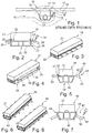
- a synopsis of the Figs. 2 and 3 shows a first embodiment of a sliding contact device 19 with a sliding strip support device 20 and a sliding strip 21 arranged thereon.
- the sliding strip support device 20 is formed from a support profile 22 and includes a catching device 23 for catching and diverting arcs 24.
- the sliding strip 21 is made of graphite and is inserted into a trapezoidal receiving groove 25 of the support profile 22 made of aluminum.
- profile elements 27 are formed with a number of rods 28 arranged regularly along the respective longitudinal side 26.
- the rods 28 here form catching elements 29 of the catching device 23.
- the profile elements 27 and the rods 28 are made of aluminum and, if necessary, can simply be replaced by arcing arcs 24 on the longitudinal sides 26 after the rods 28 have been used up.
- the rods 28 are positioned adjacent to an upper edge 30 of the support profile 22.
- the Fig. 4 shows a second embodiment of a sliding contact device 31, in which, in contrast to the sliding contact device from FIG Fig. 2 a catching device 32 is formed solely from a profile element 33.
- the profile element 33 has a leg 34 which protrudes relative to the longitudinal side 26 and which here forms catch elements 35 which are designed as teeth.
- a synopsis of the Figures 5 and 6 shows a sliding contact device 36 in which a sliding strip 37 made of graphite is attached to an upper side 38 of a sliding strip support device 39 or its support profile 40 by, for example, gluing.
- rods 42 are fastened directly to the support profile 40 adjacent to an upper edge 41 of the support profile 40, the rods 42 together forming a catching device 43 for arcs 44.
- the rods 42 are inclined in the direction of the sliding strip 37 with a distal end 45.
- the Figures 7 and 8 show a sliding contact device 46 in which, in contrast to the sliding contact device from FIG Fig. 5 a catching device 47 is arranged on the longitudinal sides 48 of the support profile 40, which consists of profile elements 49 with arranged thereon at regular intervals Bars 50 is formed.
- the rods 50 are inclined in the direction away from the contact strip 37 on the support profile 40 or the profile element 49.
Landscapes
- Engineering & Computer Science (AREA)
- Power Engineering (AREA)
- Transportation (AREA)
- Mechanical Engineering (AREA)
- Current-Collector Devices For Electrically Propelled Vehicles (AREA)
Description
- Die Erfindung betrifft eine Gleitkontaktvorrichtung sowie ein Verfahren zum Ableiten von Lichtbögen an einer Gleitkontaktvorrichtung, insbesondere für eine Stromversorgung von Fahrzeugen über einen Fahrdraht, wobei die Gleitkontaktvorrichtung eine Schleifleistenträgereinrichtung und eine daran angeordnete Schleifleiste umfasst.
- Zur Stromversorgung von schienengebundenen, aber auch von nicht schienengebundenen, mit Elektromotoren betriebenen Fahrzeugen werden Gleitkontaktvorrichtungen verwendet, die eine Schleifleiste und eine Schleifleistenträgereinrichtung umfassen. Diese Gleitkontaktvorrichtungen werden mit einer Andruckvorrichtung bzw. einem Pantograph oder einer Schwinge unter Ausbildung einer Andruckkraft gegen einen Fahrstromleiter bzw. Fahrdraht gedrückt. Dadurch wird ein Gleitkontakt ausgebildet, wodurch eine Stromversorgung des Fahrzeugs während einer Fahrt ermöglicht wird.
- Wesentlich dabei ist, dass auch während eines dynamischen Fahrbetriebs von derartigen Fahrzeugen eine möglichst kontinuierliche Aufrechterhaltung des Gleitkontakts zwischen der Schleifleiste und dem Fahrdraht gewährleistet ist. Es kann jedoch nicht immer ein ununterbrochener Kontakt zwischen der Schleifleiste und dem Fahrdraht sichergestellt werden. Insbesondere bei einer Bildung von Reif, Eis oder sonstigen Anhaftungen am Fahrdraht sind kurzzeitige Ablösungen der Schleifleiste vom Fahrdraht unvermeidlich. Unter anderem bedingt durch diese Ablösungen ist regelmäßig ein elektrischer Überschlag, bzw. eine Bildung eines Lichtbogens zwischen dem Fahrdraht und der Schleifleistenträgereinrichtung zu beobachten, welcher eine Beschädigung der Gleitkontaktvorrichtung zur Folge haben kann. Auch bereits beim bloßen Kontaktieren des Fahrdrahts mit der Schleifleiste können sich Lichtbögen ausbilden. Eine Ausbildung von Lichtbögen wird auch durch eine erhöhte Luftfeuchtigkeit im Bereich zwischen der Gleitkontaktvorrichtung und dem Fahrdraht begünstigt. Gerade die regelmäßig aus Metall ausgebildete Schleifleistenträgereinrichtung kann durch Lichtbögen stark beschädigt werden, wodurch verkürzte Inspektions- und Austauschintervalle erforderlich werden.
- Die Schleifleistenträgereinrichtung ist häufig aus einem Aluminiumprofil mit einer U-förmigen Aufnahme für die aus Hartkohle bzw. Graphit bestehende Schleifleiste ausgebildet. Die Schleifleiste kann dabei mit dem Aluminiumprofil verklebt oder auch an der U-förmigen Aufnahme formschlüssig, durch Verbiegen von Schenkeln der U-förmigen Aufnahme, geklemmt sein. Bei der Ausbildung eines Lichtbogens zwischen dem Fahrdraht und der Schleifleistenträgereinrichtung kommt es zu einem Wärmeeintrag in die Schleifleistenträgereinrichtung und die Schleifleiste, wobei auch Material der Schleifleistenträgereinrichtung geschmolzen, verdampft oder abgelöst werden kann. Bei einer wiederholten Ausbildung von Lichtbögen kann die Schleifleistenträgereinrichtung daher stellenweise aufgezehrt und dadurch geschwächt bzw. die Schleifleiste in Folge von Wärmespannungen durch Bruch zerstört werden.
- Aus der
EP 2 746 091 B1 ist eine Gleitkontaktvorrichtung bekannt, die eine Bildung von Lichtbögen zwischen einer Schleifleistenträgereinrichtung und einem Fahrdraht verhindern soll. Insbesondere ist an der Schleifleistenträgereinrichtung ein Strömungskanal ausgebildet, der während einer Fahrt des Fahrzeugs eine gezielte Führung eines Luftstromes derart ermöglicht, dass ein Lichtbogen von der Schleifleistenträgereinrichtung auf die Schleifleiste umgelenkt wird. Nachteilig ist jedoch, dass es während eines Stehens oder bei geringen Geschwindigkeiten des Fahrzeugs mangels einer Luftströmung dennoch zu einem Überschlag des Lichtbogens zwischen Fahrdraht und Schleifleistenträgereinrichtung kommt. Gleichwohl ist es auch nicht immer möglich, mittels einer ausgebildeten Luftströmung einen derartigen Überschlag sicher zu verhindern. Darüber hinaus kommt es bei einer Ableitung des Lichtbogens über die Schleifleiste zu einer unerwünschten Erwärmung der Schleifleiste. - Der vorliegenden Erfindung liegt daher die Aufgabe zugrunde, eine Gleitkontaktvorrichtung sowie ein Verfahren zum Ableiten von Lichtbögen vorzuschlagen, mittels der bzw. dem eine Beschädigung einer Gleitkontaktvorrichtung durch Lichtbögen besser verhindert werden kann.
- Diese Aufgabe wird durch eine Gleitkontaktvorrichtung mit den Merkmalen des Anspruchs 1 und ein Verfahren mit den Merkmalen des Anspruchs 17 gelöst.
- Die erfindungsgemäße Gleitkontaktvorrichtung, insbesondere für eine Stromversorgung von Fahrzeugen über einen Fahrdraht, umfasst eine Schleifleistenträgereinrichtung und eine daran angeordnete Schleifleiste, wobei die Schleifleistenträgereinrichtung eine Fangeinrichtung für Lichtbögen aufweist, wobei die Fangeinrichtung an einer Längsseite eines Tragprofils der Schleifleistenträgereinrichtung angeordnet ist, wobei die Fangeinrichtung von mehreren entlang der Längsseite angeordneten Fangelementen ausgebildet ist.
- Eine derartige Gleitkontaktvorrichtung kann mit einer aus Graphit bestehenden Schleifleiste an einem Pantographen oder einer Schwinge angebracht sein. Durch die Fangeinrichtung wird es dann möglich, zwischen der Gleitkontaktvorrichtung und den Fahrdraht überspringende Lichtbögen gezielt in die Fangeinrichtung einzuleiten. Ein Einschlag eines Lichtbogens in die Schleifleiste oder in ein die Schleifleiste halterndes Tragprofil der Schleifleistenträgereinrichtung kann so verhindert werden. Dadurch, dass die Fangeinrichtung an der Längsseite des Tragprofils angeordnet ist, kann unabhängig von einer Position des Fahrdrahts an oder benachbart der Gleitkontaktvorrichtung stets sichergestellt werden, dass auch bei einer außenmittigen Kontaktierung der Gleitkontaktvorrichtung mit dem Fahrdraht eine Ableitung eines Lichtbogens über die Fangeinrichtung möglich ist. Die Fangeinrichtung ist demnach in Art einer Blitzschutzanlage ausgebildet und stellt benachbart der Schleifleiste und dem Tragprofil einen definierten, niederohmigen oder auch gegenüber Lichtbögen resistenteren Strompfad zur Verfügung, derart, dass ein direkter Einschlag eines Lichtbogens in die Schleifleiste und/oder das Tragprofil verhindert werden kann. Da die Fangeinrichtung eine Mehrzahl von Fangelementen aufweist, die entlang der Längsseite des Tragprofils angeordnet bzw. ausgebildet sind, kommt es bei einer Zickzack-Bewegung des Fahrdrahtes an der Schleifleiste, wie sie bei einer Fahrt des Fahrzeugs stets auftritt, zu einem Auslöschen des Lichtbogens. Durch den Abstand der Fangelemente relativ zueinander wird der Lichtbogen bei einer Bewegung der Schleifleiste quer relativ zu dem Fahrdraht unterbrochen und damit ausgelöscht. Ein übermäßiger Wärmeeintrag oder ein Verzehr des Materials des Tragprofils durch Lichtbögen kann so während eines Stillstands oder einer Fahrt des Fahrzeugs und auch bei einer bloßen Kontaktierung eines Fahrdrahts mit der Gleitkontaktvorrichtung wirkungsvoll verhindert und damit eine Lebensdauer der Gleitkontaktvorrichtung verlängert werden.
- Die Fangeinrichtung kann auf einer einer Fahrtrichtung abgewandten Längsseite und/oder einer der Fahrtrichtung zugewandten Längsseite der Schleifleistenträgereinrichtung angeordnet sein. Der Fahrdraht kann dann quer relativ zu der Gleitkontaktvorrichtung verlaufen, wobei dann je nach Fahrtrichtung des Fahrzeugs die Fangeinrichtung auf einer der Längsseiten oder beiden Längsseiten des Tragprofils der Schleifleistenträgereinrichtung angeordnet sein kann. Wenn die Fangeinrichtung an beiden Längsseiten angeordnet ist bzw. jede der Längsseiten eine Fangeinrichtung aufweist, kann eine kontrollierte Ableitung und Auslöschung eines Lichtbogens stets sichergestellt werden.
- Vorteilhaft ist es, wenn die Fangeinrichtung an dem Tragprofil lösbar befestigt ist. Die Fangeinrichtung kann dann auswechselbar ausgebildet sein, sodass es möglich wird, die Fangeinrichtung bei einer Beschädigung durch Lichtbögen einfach zu ersetzen. Dann ist es auch nicht mehr erforderlich, die komplette Gleitkontaktvorrichtung auszutauschen, sondern die beschädigte Fangeinrichtung kann gegen eine neue Fangeinrichtung ersetzt werden, was eine Einsparung von Kosten ermöglicht.
- Gleichwohl ist es möglich, dass das Tragprofil die Fangeinrichtung ausbildet. Bei den aus dem Stand der Technik bekannten Tragprofilen ist prinzipiell ein Überschlag eines Lichtbogens von einem Fahrdraht an jeder Stelle des Tragprofils möglich. Wenn das Tragprofil die Fangeinrichtung ausbildet, handelt es sich bei der Fangeinrichtung um einen vorspringenden Abschnitt des Tragprofils, welcher eine äußere Kontur des zur Halterung der Schleifleiste ausgebildeten Tragprofils derart überragt, dass prinzipbedingt ein Lichtbogen in die Fangeinrichtung einschlägt, sofern ein Lichtbogen auftritt. Die Fangeinrichtung kann dann auch so beschaffen sein, dass eine Beschädigung des Teils des Tragprofils, welcher zur Halterung der Schleifleiste dient, Lichtbögen verhindert wird.
- Die Fangelemente können elektrisch leitend und voneinander beabstandet sein. Die Fangelemente können jeweils auch unterschiedlich ausgebildet sein, um einer Häufigkeit eines Einschlags eines Lichtbogens in dem Fangelement Rechnung zu tragen. Beispielsweise kann ein Fangelement in einem Mittenbereich der Längsseite länger ausgebildet sein als an einem äußeren Ende der Längsseite, da sich während eines Fahrbetriebs ein Fahrdraht häufiger in dem Mittenbereich befinden kann.
- Das Fangelement kann aus Aluminium oder einer Aluminiumlegierung, Kohlenstofffasern, Stahl, Wolfram oder Hartkohle bestehen. Aluminium weist eine gute elektrische Leitfähigkeit und Wärmeleitung auf. Weiter ist Aluminium kostengünstig erhältlich und gut verarbeitbar. Wenn das Tragprofil ebenfalls aus Aluminium ausgebildet ist, kann das Fangelement einfach mit dem Tragprofil kombiniert werden. Alternativ kann das Fangelement aus Graphit, Kupfer etc. ausgebildet sein.
- Das Fangelement kann als ein konsumierbares Fangelement ausgebildet sein. Durch einen wiederholten Einschlag von Lichtbögen kann dann das Material des Fangelements verdampft oder abgelöst werden, ohne dass es zu einer direkten Beschädigung des Tragprofils kommt. Erst nach einem vollständigen Aufbrauchen des Fangelements würde das Tragprofil dann durch Lichtbogeneinschläge beschädigt werden.
- Vorteilhaft ist es, wenn das Fangelement angrenzend einer Oberkante des Tragprofils angeordnet ist. Das Fangelement ist dann so einerseits gut an dem Tragprofil befestigbar und andererseits möglichst dicht an einem Fahrdraht positioniert. Wie sich herausgestellt hat, schlagen Lichtbögen bevorzugt an einer Oberkante eines Tragprofils ein, sodass hier dann ein kontrollierter Einschlag eines Lichtbogens in das Fangelement erfolgen kann.
- Auch ist es besonders vorteilhaft, wenn das Fangelement relativ zu der Längsseite des Tragprofils auskragend angeordnet ist. So kann das Fangelement an der Längsseite in Fahrtrichtung bzw. entgegengesetzt der Fahrtrichtung hervorspringen bzw. hervorstehen. Das Fangelement kann dann in der gleichen Richtung wie der Fahrdraht orientiert sein.
- Weiter kann das Fangelement in Richtung zu der Schleifleiste hin geneigt angeordnet sein. Das Fangelement kann dann relativ zu einer horizontalen Ebene mit einem äußeren Ende nach oben hin geneigt an dem Tragprofil positioniert sein. Eine Strecke zwischen dem Fangelement und dem Fahrdraht wird so verkürzt, wodurch auf jeden Fall sichergestellt werden kann, dass ein Lichtbogen stets in das Fangelement einschlägt.
- Weiter kann das Fangelement auch in Richtung von der Schleifleiste weg geneigt angeordnet sein. Das Fangelement kann dann mit einem äußeren Ende relativ zu einer horizontalen Ebene in einem Winkel nach unten hin geneigt an dem Tragprofil angeordnet sein. So wird es auch möglich, Lichtbögen, die aufgrund von Feuchtigkeit oder Anhaftungen von Eis an anderen Stellen des Tragprofils einschlagen können, sicher abzuleiten. Insbesondere, wenn die Fangeinrichtung aus einer Mehrzahl von Fangelementen ausgebildet ist, können diese sowohl von dem Schleifstück weg als auch zu dem Schleifstück hin geneigt, beispielsweise in einem regelmäßigen Wechsel, angeordnet sein.
- Die Fangeinrichtung kann ein Profilelement aufweisen, welches entlang der Längsseite verläuft, und ein relativ zu der Längsseite auskragender Schenkel des Profilelements sein kann. Beispielsweise kann das Profilelement im Querschnitt L-förmig ausgebildet sein und die Fangelemente ausbilden, sodass dann ein Schenkel des Profilelements an der Längsseite anliegt, und ein weiterer Schenkel des Profilelements an der Längsseite vorspringt bzw. auskragt. Dieses Profilelement kann einfach mit dem Tragprofil durch beispielsweise Schrauben oder Nieten verbunden sein. Der auskragende Schenkel des Profilelements kann entlang eines Teils der Längsseite oder entlang der gesamten Längsseite verlaufen. Eine Länge des Profilelements kann so bemessen sein, dass eine Zone von häufigen Einschlägen von Lichtbögen durch das Profilelement abgedeckt ist.
- Weiter kann vorgesehen sein, dass der auskragende Schenkel eine regelmäßige Zahnung aufweist und die Zahnung die Fangelemente ausbildet. So kann dann sichergestellt werden, dass ein Lichtbogen stets in einen Zahn des Schenkels einschlägt und nicht an einer anderen beliebigen Stelle. Die jeweiligen Zähne können eine spitze, runde oder rechteckige Form ausbilden. Auch kann eine Länge der Zähne variieren.
- Die Fangeinrichtung kann von mehreren regelmäßig oder unregelmäßig entlang der Längsseite angeordneten, relativ zu der Längsseite auskragenden Fangelementen ausgebildet sein. Bei den Fangelementen kann es sich um einzelne Bauteile handeln, die unabhängig voneinander an der Längsseite befestigt sein können. So wird es dann auch möglich, die Fangelemente jeweils in Abhängigkeit ihres Verschleißzustandes auszutauschen. Beispielsweise können die Fangelemente in einen Abstand von wenigen Zentimetern relativ zueinander entlang der Längsseite angeordnet sein. Der Abstand der Fangelemente kann einfach nach EN 62305, nach der zuletzt vor dem Prioritätstag gültigen Fassung, entsprechend der gewünschten Blitzschutzklasse berechnet werden, insbesondere, wenn ein elektrisches Feld durch die definierte Spannung des Fahrdrahtes bekannt ist.
- In einer besonders einfachen Ausführungsform kann das Fangelement von einem Stab ausgebildet sein. Der Stab kann beispielsweise in eine Bohrung in dem Tragprofil eingesetzt oder in das Tragprofil eingeschraubt sein. Eine Vielzahl von Stäben entlang der jeweiligen Längsseite des Tragprofils kann dann die Fangeinrichtung ausbilden. Besonders vorteilhaft ist hier, dass ein aerodynamisches Verhalten der Gleitkontaktvorrichtung bei hohen Fahrgeschwindigkeiten von den verwendeten Stäben kaum negativ beeinflusst wird.
- In einer weiteren Ausführungsform kann die Fangeinrichtung ein Profilelement aufweisen, welches entlang der Längsseite verlaufen kann, wobei an dem Profilelement mehrere regelmäßig entlang der Längsseite angeordnete und an dem Profilelement auskragende Stäbe angeordnet sein können, die jeweils ein Fangelement ausbilden. Im Unterschied zur zuvor beschriebenen Ausführungsform sind dann die Stäbe nicht direkt an dem Tragprofil angeordnet, sondern an dem Profilelement, welches seinerseits mit dem Tragprofil verbunden ist. Durch das Profilelement wird es möglich, bei einem Verschließ der Stäbe durch Materialabtrag in Folge von Lichtbogeneinschlag sämtliche Stäbe an einer Längsseite schnell auszutauschen. Das Profilelement kann einfach streifenförmig ausgebildet sein und an der Längsseite des Tragprofils direkt anliegen. So sind auch eine gute Wärmeableitung sowie ein guter Stromübergang zwischen dem Profilelement und dem Tragprofil sichergestellt. Weiter können konventionelle Gleitkontaktvorrichtungen einfach mit einer derartigen Fangvorrichtung nachgerüstet werden.
- Bei dem erfindungsgemäßen Verfahren zum Ableiten von Lichtbögen an einer Gleitkontaktvorrichtung, insbesondere für eine Stromversorgung von Fahrzeugen über einen Fahrdraht, wird eine Schleifleistenträgereinrichtung mit einer darin angeordneten Schleifleiste der Gleitkontaktvorrichtung mit einem Fahrdraht kontaktiert, wobei ein Lichtbogen zwischen dem Fahrdraht und der Gleitkontaktvorrichtung ausgebildet wird, wobei der Lichtbogen die Gleitkontaktvorrichtung an einer an einer Längsseite eines Tragprofils der Schleifleistenträgereinrichtung angeordneten, von mehreren entlang der Längsseite angeordneten Fangelementen ausgebildeten Fangeinrichtung der Schleifleistenträgereinrichtung kontaktiert. Hinsichtlich der Vorteile des erfindungsgemäßen Verfahrens wird auf die Vorteilsbeschreibung der erfindungsgemäßen Gleitkontaktvorrichtung verwiesen. Weitere vorteilhafte Ausführungsformen des Verfahrens ergeben sich aus den Merkmalsbeschreibungen der auf den Vorrichtungsanspruch 1 rückbezogenen Unteransprüche.
- Im Folgenden wird die Erfindung unter Bezugnahme auf die beigefügten Zeichnungen näher erläutert.
- Es zeigen:
- Fig. 1
- eine Gleitkontaktvorrichtung nach dem Stand der Technik in einer Querschnittansicht;
- Fig. 2
- eine erste Ausführungsform einer Gleitkontaktvorrichtung in einer Querschnittansicht;
- Fig. 3
- eine perspektivische Ansicht der Gleitkontaktvorrichtung aus
Fig. 2 ; - Fig. 4
- eine zweite Ausführungsform einer Gleitkontaktvorrichtung in einer perspektivischen Ansicht;
- Fig. 5
- eine dritte Ausführungsform einer Gleitkontaktvorrichtung in einer Querschnittansicht;
- Fig. 6
- eine perspektivische Ansicht der Gleitkontaktvorrichtung aus
Fig. 5 ; - Fig. 7
- eine vierte Ausführungsform einer Gleitkontaktvorrichtung in einer Querschnittansicht;
- Fig. 8
- eine perspektivische Ansicht der Gleitkontaktvorrichtung aus
Fig. 7 . - Die
Fig. 1 zeigt eine Gleitkontaktvorrichtung 10 nach dem Stand der Technik in einer Querschnittansicht, umfassend eine Schleifleistenträgereinrichtung 11 und eine Schleifleiste 12, die auf einem Tragprofil 13 der Schleifleistenträgereinrichtung 11 angeordnet und befestigt ist. Wie hier mit Linien 14 angedeutet, wird während einer Fahrt eines hier nicht dargestellten Fahrzeugs die Gleitkontaktvorrichtung 10 von einer Luftströmung 15 umströmt, die an einer Längsseite 16 der Gleitkontaktvorrichtung 10 verwirbelt. Zwischen einem Fahrdraht 17, der quer zu der Gleitkontaktvorrichtung 10 verläuft und mit dieser kontaktiert ist, und dem Tragprofil 13 ist ein Lichtbogen 18 ausgebildet. Durch den Lichtbogen 18 an dem Tragprofil 13 kommt es zu einer Ablösung eines Materials des Tragprofils 13 sowie zu einer punktuellen Erwärmung desselben. - Eine Zusammenschau der
Fig. 2 und 3 zeigt eine erste Ausführungsform einer Gleitkontaktvorrichtung 19 mit einer Schleifleistenträgereinrichtung 20 und einer daran angeordneten Schleifleiste 21. Die Schleifleistenträgereinrichtung 20 ist aus einem Tragprofil 22 ausgebildet und umfasst eine Fangeinrichtung 23 zum Fangen und Ableiten von Lichtbögen 24. Die Schleifleiste 21 besteht aus Graphit und ist in eine trapezförmige Aufnahmenut 25 des Tragprofils 22 aus Aluminium eingesetzt. An Längsseiten 26 des Tragprofils 22 sind jeweils Profilelemente 27 mit einer Anzahl regelmäßig entlang der jeweiligen Längsseite 26 angeordneten Stäben 28 ausgebildet. Die Stäbe 28 bilden hier Fangelemente 29 der Fangeinrichtung 23 aus. Die Profilelemente 27 und die Stäbe 28 bestehen aus Aluminium und können bei Bedarf einfach nach einem Verbrauch der Stäbe 28 durch Lichtbögen 24 an den Längsseiten 26 ausgetauscht werden. Insbesondere sind die Stäbe 28 an eine Oberkante 30 des Tragprofils 22 angrenzend positioniert. - Die
Fig. 4 zeigt eine zweite Ausführungsform einer Gleitkontaktvorrichtung 31, bei der im Unterschied zur Gleitkontaktvorrichtung ausFig. 2 eine Fangeinrichtung 32 alleine aus einem Profilelement 33 ausgebildet ist. Das Profilelement 33 weist einen relativ zu der Längsseite 26 auskragenden Schenkel 34 auf, der hier als Zahnung ausgebildete Fangelemente 35 ausbildet. - Eine Zusammenschau der
Fig. 5 und 6 zeigt eine Gleitkontaktvorrichtung 36, bei der eine Schleifleiste 37 aus Graphit auf einer Oberseite 38 einer Schleifleistenträgereinrichtung 39 bzw. deren Tragprofil 40 durch beispielsweise Kleben befestigt ist. Benachbart einer Oberkante 41 des Tragprofils 40 sind hier Stäbe 42 direkt an dem Tragprofil 40 befestigt, wobei die Stäbe 42 zusammen eine Fangeinrichtung 43 für Lichtbögen 44 ausbilden. Insbesondere sind die Stäbe 42 in Richtung zu der Schleifleiste 37 hin mit einem distalen Ende 45 geneigt. - Die
Fig. 7 und 8 zeigen eine Gleitkontaktvorrichtung 46, bei der im Unterschied zu der Gleitkontaktvorrichtung ausFig. 5 eine Fangeinrichtung 47 an den Längsseiten 48 des Tragprofils 40 angeordnet ist, die aus Profilelementen 49 mit daran in regelmäßigen Abständen angeordneten Stäben 50 ausgebildet ist. Insbesondere sind hier die Stäbe 50 in Richtung von der Schleifleiste 37 weg geneigt an dem Tragprofil 40 bzw. dem Profilelement 49 angeordnet.
Claims (17)
- Gleitkontaktvorrichtung (19, 31, 36, 46), insbesondere für eine Stromversorgung von Fahrzeugen über einen Fahrdraht, wobei die Gleitkontaktvorrichtung eine Schleifleistenträgereinrichtung (20, 39) und eine daran angeordnete Schleifleiste (21, 37) umfasst,
dadurch gekennzeichnet,
dass die Schleifleistenträgereinrichtung eine Fangeinrichtung (23, 32, 43, 47) für Lichtbögen (24, 44) aufweist, wobei die Fangeinrichtung an einer Längsseite (26, 48) eines Tragprofils (22, 40) der Schleifleistenträgereinrichtung angeordnet ist, und wobei die Fangeinrichtung (23, 43, 47) von mehreren entlang der Längsseite angeordneten Fangelementen (29) ausgebildet ist. - Gleitkontaktvorrichtung nach Anspruch 1,
dadurch gekennzeichnet,
dass die Fangeinrichtung (23, 32, 43, 47) auf der einer Fahrtrichtung abgewandten Längsseite (26, 48) und/oder einer der Fahrtrichtung zugewandten Längsseite (26, 48) der Schleifleistenträgereinrichtung (20, 39) angeordnet ist. - Gleitkontaktvorrichtung nach Anspruch 1 oder 2,
dadurch gekennzeichnet,
dass die Fangeinrichtung (23, 32, 43, 47) an dem Tragprofil (22, 40) lösbar befestigt ist. - Gleitkontaktvorrichtung nach Anspruch 1 oder 2,
dadurch gekennzeichnet,
dass das Tragprofil die Fangeinrichtung ausbildet. - Gleitkontaktvorrichtung nach einem der vorangehenden Ansprüche,
dadurch gekennzeichnet,
dass die Fangelemente (29, 35) elektrisch leitend und voneinander beabstandet sind. - Gleitkontaktvorrichtung nach einem der vorangehenden Ansprüche,
dadurch gekennzeichnet,
dass das Fangelement (29, 35) aus Aluminium oder einer Aluminiumlegierung, Kohlenstofffasern, Stahl, Wolfram oder Hartkohle besteht. - Gleitkontaktvorrichtung nach einem der vorangehenden Ansprüche,
dadurch gekennzeichnet,
dass das Fangelement (29, 35) als ein konsumierbares Fangelement ausgebildet ist. - Gleitkontaktvorrichtung nach einem der vorangehenden Ansprüche,
dadurch gekennzeichnet,
dass das Fangelement (29, 35) angrenzend einer Oberkante (30, 41) des Tragprofils (22, 40) angeordnet ist. - Gleitkontaktvorrichtung nach einem der vorangehenden Ansprüche,
dadurch gekennzeichnet,
dass das Fangelement (29, 35) relativ zu der Längsseite (26, 48) des Tragprofils (22, 40) auskragend angeordnet ist. - Gleitkontaktvorrichtung nach einem der vorangehenden Ansprüche,
dadurch gekennzeichnet,
dass das Fangelement in Richtung zu der Schleifleiste (21, 37) hin geneigt angeordnet ist. - Gleitkontaktvorrichtung nach einem der vorangehenden Ansprüche,
dadurch gekennzeichnet,
dass das Fangelement in Richtung von der Schleifleiste (21, 37) weg geneigt angeordnet ist. - Gleitkontaktvorrichtung nach einem der vorangehenden Ansprüche,
dadurch gekennzeichnet,
dass die Fangeinrichtung (32) ein Profilelement (33) aufweist, welches entlang der Längsseite (26) verläuft, und ein relativ zu der Längsseite auskragender Schenkel (34) des Profilelements ist. - Gleitkontaktvorrichtung nach Anspruch 12,
dadurch gekennzeichnet,
dass der auskragende Schenkel (34) eine Zahnung aufweist und die Zahnung die Fangelemente ausbildet. - Gleitkontaktvorrichtung nach einem der vorangehenden Ansprüche,
dadurch gekennzeichnet,
dass die Fangeinrichtung (23, 43, 47) von mehreren regelmäßig oder unregelmäßig entlang der Längsseite (26, 48) angeordneten und relativ zu der Längsseite auskragenden Fangelementen (29) ausgebildet ist. - Gleitkontaktvorrichtung nach Anspruch 14,
dadurch gekennzeichnet,
dass das Fangelement (29) von einem Stab (28, 50) ausgebildet ist. - Gleitkontaktvorrichtung nach einem der Ansprüche 5 bis 11,
dadurch gekennzeichnet,
dass die Fangeinrichtung (23, 43, 47) ein Profilelement (27, 49) aufweist, welches entlang der Längsseite (26, 48) verläuft, wobei an dem Profilelement mehrere regelmäßig entlang der Längsseite angeordnete und an dem Profilelement auskragende Stäbe (28, 42, 50) angeordnet sind, die jeweils ein Fangelement (29) ausbilden. - Verfahren zum Ableiten von Lichtbögen (24, 44) an einer Gleitkontaktvorrichtung (19, 31, 36, 46), für eine Stromversorgung von Fahrzeugen über einen Fahrdraht, wobei eine Schleifleistenträgereinrichtung (20, 39) mit einer daran angeordneten Schleifleiste (21, 37) der Gleitkontaktvorrichtung mit einem Fahrdraht kontaktiert wird,
dadurch gekennzeichnet,
dass ein Lichtbogen 24, 44) zwischen dem Fahrdraht und der Gleitkontaktvorrichtung ausgebildet wird, wobei der Lichtbogen die Gleitkontaktvorrichtung an einer an einer Längsseite (26, 48) eines Tragprofils (22, 40) der Schleifleistenträgereinrichtung angeordneten, von mehreren entlang der Längsseite angeordneten Fangelementen (29) ausgebildeten Fangeinrichtung (23, 32, 43, 47) der Schleifleistenträgereinrichtung kontaktiert.
Applications Claiming Priority (2)
| Application Number | Priority Date | Filing Date | Title |
|---|---|---|---|
| DE102017217638.5A DE102017217638B4 (de) | 2017-10-04 | 2017-10-04 | Gleitkontaktvorrichtung und Verfahren |
| PCT/EP2018/075925 WO2019068512A1 (de) | 2017-10-04 | 2018-09-25 | Gleitkontaktvorrichtung und verfahren |
Publications (2)
| Publication Number | Publication Date |
|---|---|
| EP3691928A1 EP3691928A1 (de) | 2020-08-12 |
| EP3691928B1 true EP3691928B1 (de) | 2021-12-01 |
Family
ID=63798948
Family Applications (1)
| Application Number | Title | Priority Date | Filing Date |
|---|---|---|---|
| EP18783382.7A Active EP3691928B1 (de) | 2017-10-04 | 2018-09-25 | Gleitkontaktvorrichtung und verfahren |
Country Status (5)
| Country | Link |
|---|---|
| EP (1) | EP3691928B1 (de) |
| CN (1) | CN111183056A (de) |
| DE (1) | DE102017217638B4 (de) |
| ES (1) | ES2905629T3 (de) |
| WO (1) | WO2019068512A1 (de) |
Families Citing this family (1)
| Publication number | Priority date | Publication date | Assignee | Title |
|---|---|---|---|---|
| DE102017223401B4 (de) * | 2017-12-20 | 2019-10-10 | Schunk Carbon Technology Gmbh | Kontakteinheit und Verfahren |
Family Cites Families (13)
| Publication number | Priority date | Publication date | Assignee | Title |
|---|---|---|---|---|
| GB560769A (en) * | 1942-10-09 | 1944-04-19 | Nathaniel Herbert Thomas | Arc quenching device for use with current collectors |
| AT256174B (de) * | 1965-09-23 | 1967-08-10 | Wiener Starkstromwerke Gmbh | Stromabnehmer-Schleifleistenträger |
| DE3412269A1 (de) * | 1984-04-02 | 1985-10-10 | Dozler, Wilhelm, Dipl.-Ing., 8012 Ottobrunn | Schleifstueck |
| DE9401585U1 (de) * | 1994-02-01 | 1994-06-23 | Schunk Kohlenstofftechnik GmbH, 35452 Heuchelheim | Schleifstück |
| JPH10285703A (ja) * | 1997-03-31 | 1998-10-23 | Toyo Tanso Kk | 電気車両用集電舟体 |
| DE202004006776U1 (de) * | 2004-04-26 | 2004-07-08 | Pantrac Gmbh | Schleifvorrichtung für absenkbare Stromabnehmer |
| JP5269525B2 (ja) * | 2008-08-29 | 2013-08-21 | 株式会社東芝 | アークホーンを備えた電気車両 |
| DE102012002749B4 (de) * | 2012-02-08 | 2026-02-26 | Libroduct Gmbh & Co. Kg | Vorrichtung für das automatische oberleitungsparallele Ausrichten der Schleifschuhe beim Andrahten der Stangenstromabnehmer bei Oberleitungsfahrzeugen |
| JP5852519B2 (ja) * | 2012-06-19 | 2016-02-03 | 公益財団法人鉄道総合技術研究所 | パンタグラフ |
| DE102012224254A1 (de) | 2012-12-21 | 2014-06-26 | Hoffmann & Co. Elektrokohle Ag | Gleitkontaktvorrichtung |
| TWI523773B (zh) * | 2013-01-18 | 2016-03-01 | 國立臺灣科技大學 | 電氣列車的集電設備及其集電方法 |
| CN203543697U (zh) * | 2013-09-30 | 2014-04-16 | 北京万高众业科技发展有限公司 | 受电弓碳滑板 |
| CN205365266U (zh) * | 2016-01-19 | 2016-07-06 | 苏州凯博易控驱动技术有限公司 | 用于无轨电车集电器的安全系统 |
-
2017
- 2017-10-04 DE DE102017217638.5A patent/DE102017217638B4/de not_active Expired - Fee Related
-
2018
- 2018-09-25 WO PCT/EP2018/075925 patent/WO2019068512A1/de not_active Ceased
- 2018-09-25 EP EP18783382.7A patent/EP3691928B1/de active Active
- 2018-09-25 CN CN201880064914.0A patent/CN111183056A/zh active Pending
- 2018-09-25 ES ES18783382T patent/ES2905629T3/es active Active
Also Published As
| Publication number | Publication date |
|---|---|
| EP3691928A1 (de) | 2020-08-12 |
| WO2019068512A1 (de) | 2019-04-11 |
| DE102017217638B4 (de) | 2020-07-09 |
| ES2905629T3 (es) | 2022-04-11 |
| DE102017217638A1 (de) | 2019-04-04 |
| CN111183056A (zh) | 2020-05-19 |
Similar Documents
| Publication | Publication Date | Title |
|---|---|---|
| EP3501877B1 (de) | Kontakteinheit und verfahren | |
| WO2015110328A2 (de) | Lineares transportsystem und verfahren zum betreiben des linearen transportsystems | |
| DE4310762A1 (de) | Plasmabrenner-Düse | |
| EP3296141B1 (de) | Stromabnehmer, schleifleitungssystem und schleifkontakt | |
| WO1997036764A1 (de) | Verfahren und vorrichtung zur kopplung von elastischen und starren fahrleitungssystemen | |
| EP1206791A1 (de) | Anschlussanordnung für eine stabförmige zweiendige entladungslampe | |
| DE102017217638B4 (de) | Gleitkontaktvorrichtung und Verfahren | |
| DE2047896C3 (de) | MetaHspritzpistole | |
| EP2284442A2 (de) | Elektrostatischer Abscheider und Heizungssystem | |
| DE102019214432B4 (de) | Baugruppe für einen Hochspannungs-Leistungsschalter und entsprechender Hochspannungs-Leistungsschalter | |
| EP2698272A2 (de) | Stromschienenauflauf | |
| DD201835A5 (de) | Elektrode fuer lichtbogenoefen | |
| EP0592819A1 (de) | Streckentrenner mit Isolierkufen | |
| DE102007043891B4 (de) | Kontaktrollenvorrichtung und Oberflächenbehandlungsanlage für Metallstrang | |
| DE19903784B4 (de) | Vorrichtung zur Herstellung eines Schweißkontakts | |
| DE326224C (de) | Vorrichtung zum Verspritzen geschmolzenen Metalls | |
| EP3328576B1 (de) | Elektroschlacke-umschmelzanlage | |
| DE102004020886B4 (de) | Schleifvorrichtung für absenkbare Stromabnehmer | |
| DE19730375A1 (de) | Verfahren und Vorrichtung zum Auslenken einer Walzader | |
| EP3441257B1 (de) | Streckentrennvorrichtung und verwendung einer solchen | |
| EP3703971B1 (de) | Oberleitungsanordnung und verfahren zur montage einer oberleitungsanordnung | |
| DE102005011618A1 (de) | Stromabnehmer für ein Fahrzeug, insbesondere ein Eisenbahn- oder ein Straßenbahnfahrzeug | |
| DE60316166T2 (de) | Antenne für die Eisenbahn mit Schutzmittel gegen Hochspannungen | |
| DE102023213291A1 (de) | Befestigungsvorrichtung und Fahrleitungsanlage mit Befestigungsvorrichtung | |
| DE202015100623U1 (de) | Stromabnehmer und Schleifleitungssystem |
Legal Events
| Date | Code | Title | Description |
|---|---|---|---|
| STAA | Information on the status of an ep patent application or granted ep patent |
Free format text: STATUS: UNKNOWN |
|
| STAA | Information on the status of an ep patent application or granted ep patent |
Free format text: STATUS: THE INTERNATIONAL PUBLICATION HAS BEEN MADE |
|
| PUAI | Public reference made under article 153(3) epc to a published international application that has entered the european phase |
Free format text: ORIGINAL CODE: 0009012 |
|
| STAA | Information on the status of an ep patent application or granted ep patent |
Free format text: STATUS: REQUEST FOR EXAMINATION WAS MADE |
|
| 17P | Request for examination filed |
Effective date: 20200421 |
|
| AK | Designated contracting states |
Kind code of ref document: A1 Designated state(s): AL AT BE BG CH CY CZ DE DK EE ES FI FR GB GR HR HU IE IS IT LI LT LU LV MC MK MT NL NO PL PT RO RS SE SI SK SM TR |
|
| AX | Request for extension of the european patent |
Extension state: BA ME |
|
| DAV | Request for validation of the european patent (deleted) | ||
| DAX | Request for extension of the european patent (deleted) | ||
| REG | Reference to a national code |
Ref country code: DE Ref legal event code: R079 Ref document number: 502018008058 Country of ref document: DE Free format text: PREVIOUS MAIN CLASS: B60L0005080000 Ipc: B60L0005200000 |
|
| GRAP | Despatch of communication of intention to grant a patent |
Free format text: ORIGINAL CODE: EPIDOSNIGR1 |
|
| STAA | Information on the status of an ep patent application or granted ep patent |
Free format text: STATUS: GRANT OF PATENT IS INTENDED |
|
| RIC1 | Information provided on ipc code assigned before grant |
Ipc: B60L 5/20 20060101AFI20210610BHEP |
|
| INTG | Intention to grant announced |
Effective date: 20210706 |
|
| GRAS | Grant fee paid |
Free format text: ORIGINAL CODE: EPIDOSNIGR3 |
|
| GRAA | (expected) grant |
Free format text: ORIGINAL CODE: 0009210 |
|
| STAA | Information on the status of an ep patent application or granted ep patent |
Free format text: STATUS: THE PATENT HAS BEEN GRANTED |
|
| AK | Designated contracting states |
Kind code of ref document: B1 Designated state(s): AL AT BE BG CH CY CZ DE DK EE ES FI FR GB GR HR HU IE IS IT LI LT LU LV MC MK MT NL NO PL PT RO RS SE SI SK SM TR |
|
| REG | Reference to a national code |
Ref country code: GB Ref legal event code: FG4D Free format text: NOT ENGLISH |
|
| REG | Reference to a national code |
Ref country code: AT Ref legal event code: REF Ref document number: 1451445 Country of ref document: AT Kind code of ref document: T Effective date: 20211215 Ref country code: CH Ref legal event code: EP |
|
| REG | Reference to a national code |
Ref country code: IE Ref legal event code: FG4D Free format text: LANGUAGE OF EP DOCUMENT: GERMAN |
|
| REG | Reference to a national code |
Ref country code: DE Ref legal event code: R096 Ref document number: 502018008058 Country of ref document: DE |
|
| REG | Reference to a national code |
Ref country code: NL Ref legal event code: FP |
|
| REG | Reference to a national code |
Ref country code: LT Ref legal event code: MG9D |
|
| REG | Reference to a national code |
Ref country code: ES Ref legal event code: FG2A Ref document number: 2905629 Country of ref document: ES Kind code of ref document: T3 Effective date: 20220411 |
|
| PG25 | Lapsed in a contracting state [announced via postgrant information from national office to epo] |
Ref country code: RS Free format text: LAPSE BECAUSE OF FAILURE TO SUBMIT A TRANSLATION OF THE DESCRIPTION OR TO PAY THE FEE WITHIN THE PRESCRIBED TIME-LIMIT Effective date: 20211201 Ref country code: LT Free format text: LAPSE BECAUSE OF FAILURE TO SUBMIT A TRANSLATION OF THE DESCRIPTION OR TO PAY THE FEE WITHIN THE PRESCRIBED TIME-LIMIT Effective date: 20211201 Ref country code: FI Free format text: LAPSE BECAUSE OF FAILURE TO SUBMIT A TRANSLATION OF THE DESCRIPTION OR TO PAY THE FEE WITHIN THE PRESCRIBED TIME-LIMIT Effective date: 20211201 Ref country code: BG Free format text: LAPSE BECAUSE OF FAILURE TO SUBMIT A TRANSLATION OF THE DESCRIPTION OR TO PAY THE FEE WITHIN THE PRESCRIBED TIME-LIMIT Effective date: 20220301 |
|
| PG25 | Lapsed in a contracting state [announced via postgrant information from national office to epo] |
Ref country code: SE Free format text: LAPSE BECAUSE OF FAILURE TO SUBMIT A TRANSLATION OF THE DESCRIPTION OR TO PAY THE FEE WITHIN THE PRESCRIBED TIME-LIMIT Effective date: 20211201 Ref country code: PL Free format text: LAPSE BECAUSE OF FAILURE TO SUBMIT A TRANSLATION OF THE DESCRIPTION OR TO PAY THE FEE WITHIN THE PRESCRIBED TIME-LIMIT Effective date: 20211201 Ref country code: NO Free format text: LAPSE BECAUSE OF FAILURE TO SUBMIT A TRANSLATION OF THE DESCRIPTION OR TO PAY THE FEE WITHIN THE PRESCRIBED TIME-LIMIT Effective date: 20220301 Ref country code: LV Free format text: LAPSE BECAUSE OF FAILURE TO SUBMIT A TRANSLATION OF THE DESCRIPTION OR TO PAY THE FEE WITHIN THE PRESCRIBED TIME-LIMIT Effective date: 20211201 Ref country code: HR Free format text: LAPSE BECAUSE OF FAILURE TO SUBMIT A TRANSLATION OF THE DESCRIPTION OR TO PAY THE FEE WITHIN THE PRESCRIBED TIME-LIMIT Effective date: 20211201 Ref country code: GR Free format text: LAPSE BECAUSE OF FAILURE TO SUBMIT A TRANSLATION OF THE DESCRIPTION OR TO PAY THE FEE WITHIN THE PRESCRIBED TIME-LIMIT Effective date: 20220302 |
|
| PG25 | Lapsed in a contracting state [announced via postgrant information from national office to epo] |
Ref country code: SM Free format text: LAPSE BECAUSE OF FAILURE TO SUBMIT A TRANSLATION OF THE DESCRIPTION OR TO PAY THE FEE WITHIN THE PRESCRIBED TIME-LIMIT Effective date: 20211201 Ref country code: SK Free format text: LAPSE BECAUSE OF FAILURE TO SUBMIT A TRANSLATION OF THE DESCRIPTION OR TO PAY THE FEE WITHIN THE PRESCRIBED TIME-LIMIT Effective date: 20211201 Ref country code: RO Free format text: LAPSE BECAUSE OF FAILURE TO SUBMIT A TRANSLATION OF THE DESCRIPTION OR TO PAY THE FEE WITHIN THE PRESCRIBED TIME-LIMIT Effective date: 20211201 Ref country code: PT Free format text: LAPSE BECAUSE OF FAILURE TO SUBMIT A TRANSLATION OF THE DESCRIPTION OR TO PAY THE FEE WITHIN THE PRESCRIBED TIME-LIMIT Effective date: 20220401 Ref country code: EE Free format text: LAPSE BECAUSE OF FAILURE TO SUBMIT A TRANSLATION OF THE DESCRIPTION OR TO PAY THE FEE WITHIN THE PRESCRIBED TIME-LIMIT Effective date: 20211201 Ref country code: CZ Free format text: LAPSE BECAUSE OF FAILURE TO SUBMIT A TRANSLATION OF THE DESCRIPTION OR TO PAY THE FEE WITHIN THE PRESCRIBED TIME-LIMIT Effective date: 20211201 |
|
| REG | Reference to a national code |
Ref country code: DE Ref legal event code: R097 Ref document number: 502018008058 Country of ref document: DE |
|
| PG25 | Lapsed in a contracting state [announced via postgrant information from national office to epo] |
Ref country code: IS Free format text: LAPSE BECAUSE OF FAILURE TO SUBMIT A TRANSLATION OF THE DESCRIPTION OR TO PAY THE FEE WITHIN THE PRESCRIBED TIME-LIMIT Effective date: 20220401 |
|
| PLBE | No opposition filed within time limit |
Free format text: ORIGINAL CODE: 0009261 |
|
| STAA | Information on the status of an ep patent application or granted ep patent |
Free format text: STATUS: NO OPPOSITION FILED WITHIN TIME LIMIT |
|
| PG25 | Lapsed in a contracting state [announced via postgrant information from national office to epo] |
Ref country code: DK Free format text: LAPSE BECAUSE OF FAILURE TO SUBMIT A TRANSLATION OF THE DESCRIPTION OR TO PAY THE FEE WITHIN THE PRESCRIBED TIME-LIMIT Effective date: 20211201 Ref country code: AL Free format text: LAPSE BECAUSE OF FAILURE TO SUBMIT A TRANSLATION OF THE DESCRIPTION OR TO PAY THE FEE WITHIN THE PRESCRIBED TIME-LIMIT Effective date: 20211201 |
|
| 26N | No opposition filed |
Effective date: 20220902 |
|
| PG25 | Lapsed in a contracting state [announced via postgrant information from national office to epo] |
Ref country code: SI Free format text: LAPSE BECAUSE OF FAILURE TO SUBMIT A TRANSLATION OF THE DESCRIPTION OR TO PAY THE FEE WITHIN THE PRESCRIBED TIME-LIMIT Effective date: 20211201 |
|
| PG25 | Lapsed in a contracting state [announced via postgrant information from national office to epo] |
Ref country code: MC Free format text: LAPSE BECAUSE OF FAILURE TO SUBMIT A TRANSLATION OF THE DESCRIPTION OR TO PAY THE FEE WITHIN THE PRESCRIBED TIME-LIMIT Effective date: 20211201 |
|
| REG | Reference to a national code |
Ref country code: CH Ref legal event code: PL |
|
| GBPC | Gb: european patent ceased through non-payment of renewal fee |
Effective date: 20220925 |
|
| P01 | Opt-out of the competence of the unified patent court (upc) registered |
Effective date: 20230524 |
|
| PG25 | Lapsed in a contracting state [announced via postgrant information from national office to epo] |
Ref country code: LU Free format text: LAPSE BECAUSE OF NON-PAYMENT OF DUE FEES Effective date: 20220925 |
|
| PG25 | Lapsed in a contracting state [announced via postgrant information from national office to epo] |
Ref country code: LI Free format text: LAPSE BECAUSE OF NON-PAYMENT OF DUE FEES Effective date: 20220930 Ref country code: IE Free format text: LAPSE BECAUSE OF NON-PAYMENT OF DUE FEES Effective date: 20220925 Ref country code: CH Free format text: LAPSE BECAUSE OF NON-PAYMENT OF DUE FEES Effective date: 20220930 |
|
| PG25 | Lapsed in a contracting state [announced via postgrant information from national office to epo] |
Ref country code: GB Free format text: LAPSE BECAUSE OF NON-PAYMENT OF DUE FEES Effective date: 20220925 |
|
| PG25 | Lapsed in a contracting state [announced via postgrant information from national office to epo] |
Ref country code: CY Free format text: LAPSE BECAUSE OF FAILURE TO SUBMIT A TRANSLATION OF THE DESCRIPTION OR TO PAY THE FEE WITHIN THE PRESCRIBED TIME-LIMIT Effective date: 20211201 |
|
| PG25 | Lapsed in a contracting state [announced via postgrant information from national office to epo] |
Ref country code: MK Free format text: LAPSE BECAUSE OF FAILURE TO SUBMIT A TRANSLATION OF THE DESCRIPTION OR TO PAY THE FEE WITHIN THE PRESCRIBED TIME-LIMIT Effective date: 20211201 Ref country code: HU Free format text: LAPSE BECAUSE OF FAILURE TO SUBMIT A TRANSLATION OF THE DESCRIPTION OR TO PAY THE FEE WITHIN THE PRESCRIBED TIME-LIMIT; INVALID AB INITIO Effective date: 20180925 |
|
| PG25 | Lapsed in a contracting state [announced via postgrant information from national office to epo] |
Ref country code: MT Free format text: LAPSE BECAUSE OF FAILURE TO SUBMIT A TRANSLATION OF THE DESCRIPTION OR TO PAY THE FEE WITHIN THE PRESCRIBED TIME-LIMIT Effective date: 20211201 |
|
| REG | Reference to a national code |
Ref country code: AT Ref legal event code: MM01 Ref document number: 1451445 Country of ref document: AT Kind code of ref document: T Effective date: 20230925 |
|
| PG25 | Lapsed in a contracting state [announced via postgrant information from national office to epo] |
Ref country code: AT Free format text: LAPSE BECAUSE OF NON-PAYMENT OF DUE FEES Effective date: 20230925 |
|
| PG25 | Lapsed in a contracting state [announced via postgrant information from national office to epo] |
Ref country code: AT Free format text: LAPSE BECAUSE OF NON-PAYMENT OF DUE FEES Effective date: 20230925 |
|
| PGFP | Annual fee paid to national office [announced via postgrant information from national office to epo] |
Ref country code: DE Payment date: 20250926 Year of fee payment: 8 |
|
| PGFP | Annual fee paid to national office [announced via postgrant information from national office to epo] |
Ref country code: NL Payment date: 20250925 Year of fee payment: 8 Ref country code: IT Payment date: 20250922 Year of fee payment: 8 |
|
| PGFP | Annual fee paid to national office [announced via postgrant information from national office to epo] |
Ref country code: BE Payment date: 20250925 Year of fee payment: 8 |
|
| PGFP | Annual fee paid to national office [announced via postgrant information from national office to epo] |
Ref country code: FR Payment date: 20250925 Year of fee payment: 8 |
|
| PG25 | Lapsed in a contracting state [announced via postgrant information from national office to epo] |
Ref country code: TR Free format text: LAPSE BECAUSE OF FAILURE TO SUBMIT A TRANSLATION OF THE DESCRIPTION OR TO PAY THE FEE WITHIN THE PRESCRIBED TIME-LIMIT Effective date: 20211201 |
|
| PGFP | Annual fee paid to national office [announced via postgrant information from national office to epo] |
Ref country code: ES Payment date: 20251008 Year of fee payment: 8 |
|
| PGFP | Annual fee paid to national office [announced via postgrant information from national office to epo] |
Ref country code: AT Payment date: 20260410 Year of fee payment: 5 |