EP3691908B1 - Commande de moteur de support sur la base de la vitesse et du couple - Google Patents
Commande de moteur de support sur la base de la vitesse et du couple Download PDFInfo
- Publication number
- EP3691908B1 EP3691908B1 EP17927982.3A EP17927982A EP3691908B1 EP 3691908 B1 EP3691908 B1 EP 3691908B1 EP 17927982 A EP17927982 A EP 17927982A EP 3691908 B1 EP3691908 B1 EP 3691908B1
- Authority
- EP
- European Patent Office
- Prior art keywords
- drive roller
- velocity
- torque
- roller motor
- motor
- Prior art date
- Legal status (The legal status is an assumption and is not a legal conclusion. Google has not performed a legal analysis and makes no representation as to the accuracy of the status listed.)
- Active
Links
Images


Classifications
-
- B—PERFORMING OPERATIONS; TRANSPORTING
- B65—CONVEYING; PACKING; STORING; HANDLING THIN OR FILAMENTARY MATERIAL
- B65H—HANDLING THIN OR FILAMENTARY MATERIAL, e.g. SHEETS, WEBS, CABLES
- B65H5/00—Feeding articles separated from piles; Feeding articles to machines
- B65H5/06—Feeding articles separated from piles; Feeding articles to machines by rollers or balls, e.g. between rollers
-
- B—PERFORMING OPERATIONS; TRANSPORTING
- B41—PRINTING; LINING MACHINES; TYPEWRITERS; STAMPS
- B41J—TYPEWRITERS; SELECTIVE PRINTING MECHANISMS, i.e. MECHANISMS PRINTING OTHERWISE THAN FROM A FORME; CORRECTION OF TYPOGRAPHICAL ERRORS
- B41J11/00—Devices or arrangements of selective printing mechanisms, e.g. ink-jet printers or thermal printers, for supporting or handling copy material in sheet or web form
- B41J11/02—Platens
- B41J11/14—Platen-shift mechanisms; Driving gear therefor
-
- B—PERFORMING OPERATIONS; TRANSPORTING
- B41—PRINTING; LINING MACHINES; TYPEWRITERS; STAMPS
- B41J—TYPEWRITERS; SELECTIVE PRINTING MECHANISMS, i.e. MECHANISMS PRINTING OTHERWISE THAN FROM A FORME; CORRECTION OF TYPOGRAPHICAL ERRORS
- B41J13/00—Devices or arrangements of selective printing mechanisms, e.g. ink-jet printers or thermal printers, specially adapted for supporting or handling copy material in short lengths, e.g. sheets
- B41J13/02—Rollers
- B41J13/03—Rollers driven, e.g. feed rollers separate from platen
-
- B—PERFORMING OPERATIONS; TRANSPORTING
- B41—PRINTING; LINING MACHINES; TYPEWRITERS; STAMPS
- B41J—TYPEWRITERS; SELECTIVE PRINTING MECHANISMS, i.e. MECHANISMS PRINTING OTHERWISE THAN FROM A FORME; CORRECTION OF TYPOGRAPHICAL ERRORS
- B41J29/00—Details of, or accessories for, typewriters or selective printing mechanisms not otherwise provided for
- B41J29/38—Drives, motors, controls or automatic cut-off devices for the entire printing mechanism
-
- B—PERFORMING OPERATIONS; TRANSPORTING
- B65—CONVEYING; PACKING; STORING; HANDLING THIN OR FILAMENTARY MATERIAL
- B65H—HANDLING THIN OR FILAMENTARY MATERIAL, e.g. SHEETS, WEBS, CABLES
- B65H5/00—Feeding articles separated from piles; Feeding articles to machines
- B65H5/06—Feeding articles separated from piles; Feeding articles to machines by rollers or balls, e.g. between rollers
- B65H5/062—Feeding articles separated from piles; Feeding articles to machines by rollers or balls, e.g. between rollers between rollers or balls
-
- B—PERFORMING OPERATIONS; TRANSPORTING
- B65—CONVEYING; PACKING; STORING; HANDLING THIN OR FILAMENTARY MATERIAL
- B65H—HANDLING THIN OR FILAMENTARY MATERIAL, e.g. SHEETS, WEBS, CABLES
- B65H7/00—Controlling article feeding, separating, pile-advancing, or associated apparatus, to take account of incorrect feeding, absence of articles, or presence of faulty articles
- B65H7/02—Controlling article feeding, separating, pile-advancing, or associated apparatus, to take account of incorrect feeding, absence of articles, or presence of faulty articles by feelers or detectors
-
- B—PERFORMING OPERATIONS; TRANSPORTING
- B41—PRINTING; LINING MACHINES; TYPEWRITERS; STAMPS
- B41J—TYPEWRITERS; SELECTIVE PRINTING MECHANISMS, i.e. MECHANISMS PRINTING OTHERWISE THAN FROM A FORME; CORRECTION OF TYPOGRAPHICAL ERRORS
- B41J11/00—Devices or arrangements of selective printing mechanisms, e.g. ink-jet printers or thermal printers, for supporting or handling copy material in sheet or web form
- B41J11/36—Blanking or long feeds; Feeding to a particular line, e.g. by rotation of platen or feed roller
- B41J11/42—Controlling printing material conveyance for accurate alignment of the printing material with the printhead; Print registering
-
- B—PERFORMING OPERATIONS; TRANSPORTING
- B65—CONVEYING; PACKING; STORING; HANDLING THIN OR FILAMENTARY MATERIAL
- B65H—HANDLING THIN OR FILAMENTARY MATERIAL, e.g. SHEETS, WEBS, CABLES
- B65H2513/00—Dynamic entities; Timing aspects
- B65H2513/10—Speed
-
- B—PERFORMING OPERATIONS; TRANSPORTING
- B65—CONVEYING; PACKING; STORING; HANDLING THIN OR FILAMENTARY MATERIAL
- B65H—HANDLING THIN OR FILAMENTARY MATERIAL, e.g. SHEETS, WEBS, CABLES
- B65H2513/00—Dynamic entities; Timing aspects
- B65H2513/10—Speed
- B65H2513/11—Speed angular
-
- B—PERFORMING OPERATIONS; TRANSPORTING
- B65—CONVEYING; PACKING; STORING; HANDLING THIN OR FILAMENTARY MATERIAL
- B65H—HANDLING THIN OR FILAMENTARY MATERIAL, e.g. SHEETS, WEBS, CABLES
- B65H2515/00—Physical entities not provided for in groups B65H2511/00 or B65H2513/00
- B65H2515/30—Forces; Stresses
- B65H2515/32—Torque e.g. braking torque
Definitions
- media may be fed from a source via a feed roller to a destination via a drive roller that receives the media from the feed roller.
- the source may include an input tray.
- the destination may include an output tray or another intermediate location along a print path.
- the media may include paper.
- the feed roller and the drive roller may be respectively operated by feed roller and drive roller motors.
- the terms “a” and “an” are intended to denote at least one of a particular element.
- the term “includes” means includes but not limited to, the term “including” means including but not limited to.
- the term “based on” means based at least in part on.
- Velocity and torque based media motor control apparatuses, methods for velocity and torque based media motor control, and non-transitory computer readable media having stored thereon machine readable instructions to provide velocity and torque based media motor control are disclosed herein.
- the apparatuses, methods, and non-transitory computer readable media disclosed herein provide for dynamic control of media motors depending, for example, on location of media, and/or operational velocity and/or torque associated with the media motors.
- media may be fed from a source via a feed roller to a destination via a drive roller that receives the media from the feed roller.
- the feed roller and the drive roller may be respectively operated by feed roller and drive roller motors.
- As the media is being fed from the feed roller to the drive roller it is technically challenging to control the tension imparted on the media by the drive roller which may operate at a higher rotational velocity compared to the feed roller.
- the apparatuses, methods, and non-transitory computer readable media disclosed herein provide for control of the feed roller and drive roller motors to impart different tension values on the media depending on the operational velocity and torque of the feed roller and drive roller motors. For example, as media is being fed from the feed roller to the drive roller, a determination is made as to whether the torque for the drive roller motor is greater than a torque target. In response to a determination that the torque for the drive roller motor is greater than the torque target, the torque for the drive roller motor may be reduced to the torque target.
- the torque for the drive roller motor may be dynamically controlled in response to a determination that the torque for the drive roller motor is greater than the torque target. Further, the torque for the drive roller motor may be maintained at the torque target, and variations in the velocity for the drive roller motor may be allowed during the maintenance of the torque for the drive roller motor at the torque target. In this manner, the torque for the drive roller motor may be dynamically controlled based on an analysis of the torque for the drive roller motor relative to the torque target, and the velocity for the drive roller motor may also be controlled as disclosed herein.
- modules may be any combination of hardware and programming to implement the functionalities of the respective modules.
- the combinations of hardware and programming may be implemented in a number of different ways.
- the programming for the modules may be processor executable instructions stored on a non-transitory machine-readable storage medium and the hardware for the modules may include a processing resource to execute those instructions.
- a computing device implementing such modules may include the machine-readable storage medium storing the instructions and the processing resource to execute the instructions, or the machine-readable storage medium may be separately stored and accessible by the computing device and the processing resource.
- some modules may be implemented in circuitry.
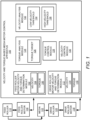
- Figure 1 illustrates an example layout of a velocity and torque based media motor control apparatus (hereinafter also referred to as "apparatus 100").
- the apparatus 100 may include a feed roller motor velocity and torque determination module 102 to ascertain a velocity 104 and a torque 106 for a feed roller motor 108 associated with (i.e., imparts motion of) a feed roller 110.
- the feed roller 110 may include an upper roller and a lower roller in the orientation Figures 3-10 .
- a drive roller motor velocity and torque determination module 112 is to ascertain a velocity 114 and a torque 116 for a drive roller motor 118 associated with (i.e., imparts motion of) a drive roller 120 that is to receive media 122 from the feed roller 110.
- the drive roller 120 may include an upper roller and a lower roller in the orientation Figures 3-10 .
- the media 122 may include paper.
- the ascertained velocity 114 for the drive roller motor 118 associated with the drive roller 120 may be greater than the ascertained velocity 104 for the feed roller motor 108 associated with the feed roller 110. That is, the velocity 114 for the drive roller motor 118 associated with the drive roller 120 may be set to be greater than the velocity 104 for the feed roller motor 108 associated with the feed roller 110.
- the drive roller motor velocity and torque determination module 112 is to ascertain, after a specified acceleration distance of the drive roller motor 118, the velocity 114 and torque 116 for the drive roller motor 118 associated with the drive roller 120 that is to receive the media 122 from the feed roller 110.
- a torque analysis module 124 is to determine whether the torque 116 for the drive roller motor 118 is greater than a torque target 126.
- a torque control module 128 is to reduce the torque 116 for the drive roller motor 118 to the torque target 126. Further, the torque control module 128 is to maintain the torque 116 (e.g., the reduced torque 116) for the drive roller motor 118 at the torque target 126.
- a velocity control module 130 is to allow, during the maintenance of the torque 116 for the drive roller motor 118 at the torque target 126, variations in the velocity 114 for the drive roller motor 118.
- a velocity analysis module 132 is to determine whether the velocity 114 for the drive roller motor 118 associated with the drive roller 120 is less than a low velocity threshold 134. In response to a determination that the velocity 114 for the drive roller motor 118 associated with the drive roller 120 is less than the low velocity threshold 134, the velocity control module 130 is to generate an indication of stalling of the drive roller motor 118.
- the velocity analysis module 132 is to further determine whether the velocity 114 for the drive roller motor 118 associated with the drive roller 120 is greater than a high velocity threshold 136. In response to a determination that the velocity 114 for the drive roller motor 118 associated with the drive roller 120 is greater than the high velocity threshold 136, the velocity control module 130 is to reduce the velocity 114 for the drive roller motor 118 to the high velocity threshold 136. Further, the velocity control module 130 is to maintain (e.g., after the reduction) the velocity 114 for the drive roller motor 118 at the high velocity threshold 136. Further, the torque control module 128 is to allow, during the maintenance of the velocity 114 for the drive roller motor 118 at the high velocity threshold 136, variations in the torque 116 for the drive roller motor 118.
- Figure 2 illustrates a flowchart to illustrate operation of the apparatus 100.
- the drive roller motor 118 may impart a constant velocity 114 on the drive roller 120.
- the drive roller motor velocity and torque determination module 112 is to ascertain the velocity 114 and the torque 116 for the drive roller motor 118 associated with the drive roller 120 that is to receive the media 122 from the feed roller 110.
- the drive roller motor velocity and torque determination module 112 is to ascertain, after a specified acceleration distance of the drive roller motor 118, the velocity 114 and the torque 116 for the drive roller motor 118 associated with the drive roller 120 that is to receive the media 122 from the feed roller 110.
- the torque analysis module 124 is to determine whether the torque 116 for the drive roller motor 118 is greater than the torque target 126.
- the torque control module 128 in response to a determination that the torque 116 for the drive roller motor 118 is greater than the torque target 126, the torque control module 128 is to reduce the torque 116 for the drive roller motor 118 to the torque target 126. Further, the torque control module 128 is to maintain the torque 116 for the drive roller motor 118 at the torque target 126.
- the velocity analysis module 132 is to determine whether the velocity 114 for the drive roller motor 118 associated with the drive roller 120 is less than the low velocity threshold 134.
- the velocity control module 130 in response to a determination that the velocity 114 for the drive roller motor 118 associated with the drive roller 120 is less than the low velocity threshold 134, the velocity control module 130 is to generate an indication of stalling of the drive roller motor 118.
- the velocity analysis module 132 is to determine whether the velocity 114 for the drive roller motor 118 associated with the drive roller 120 is greater than the high velocity threshold 136.
- the velocity control module 130 in response to a determination that the velocity 114 for the drive roller motor 118 associated with the drive roller 120 is greater than the high velocity threshold 136, the velocity control module 130 is to reduce the velocity 114 for the drive roller motor 118 to the high velocity threshold 136. Further, the velocity control module 130 is to maintain the velocity 114 for the drive roller motor 118 at the high velocity threshold 136. Further, the torque control module 128 is to allow, during the maintenance of the velocity 114 for the drive roller motor 118 at the high velocity threshold 136, variations in the torque 116 for the drive roller motor 118.
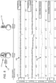
- Figure 3 illustrates torque and velocity with respect to a feed roller motor associated with a feed roller and a drive roller motor associated with a drive roller at start-up to illustrate operation of the apparatus 100.
- the graphs of Figures 3-10 illustrate torque and velocity with respect to the feed roller motor associated with the feed roller and the drive roller motor associated with the drive roller with respect to the entire cycle of the flowchart of Figure 2 to illustrate operation of the apparatus 100.
- the feed roller motor 108 may impart the velocity 104 on the feed roller 110.
- the drive roller motor 118 may impart the constant velocity 114 on the drive roller 120.
- the feed roller motor 108 and the drive roller motor 118 may start from rest, and torque may be respectively applied to the feed roller 110 and the drive roller 120 to turn (e.g., rotate) the feed roller 110 and the drive roller 120.
- Figure 4 illustrates torque and velocity with respect to the feed roller motor associated with the feed roller and the drive roller motor associated with the drive roller at steady state velocity with no media to illustrate operation of the apparatus 100.
- the feed roller motor 108 and the drive roller motor 118 may be at steady state velocity, with the drive roller motor 118 being operated at a faster velocity compared to the feed roller motor 108 to impart the faster velocity on the feed roller 110 compared to the drive roller 120.
- Figure 5 illustrates torque and velocity with respect to the feed roller motor associated with the feed roller and the drive roller motor associated with the drive roller as media enters the feed roller to illustrate operation of the apparatus 100.
- the velocity and torque of the feed roller motor 108 imparted on the feed roller 110 and the drive roller motor 118 imparted on the drive roller 120 may remain constant.
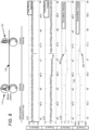
- Figure 6 illustrates torque and velocity with respect to the feed roller motor associated with the feed roller and the drive roller motor associated with the drive roller as media enters the drive roller from the feed roller to illustrate operation of the apparatus 100.
- the velocity at of the drive roller motor 118 with respect to the drive roller 120 may decrease.
- the torque at of the drive roller motor 118 with respect to the drive roller 120 may increase.
- the torque control module 128 may maintain the torque 116 for the drive roller motor 118 at the torque target 126.
- Figure 7 illustrates torque and velocity with respect to the feed roller motor associated with the feed roller and the drive roller motor associated with the drive roller as media is tensioned between the drive roller and the feed roller to illustrate operation of the apparatus 100.
- the velocity control module 130 may allow, during the maintenance of the torque 116 for the drive roller motor 118 at the torque target 126, variations in the velocity 114 for the drive roller motor 118. Further, at 702, the torque 116 may be held constant to maintain a constant tension in the media 122.
- Figure 8 illustrates torque and velocity with respect to the feed roller motor associated with the feed roller and the drive roller motor associated with the drive roller as media begins to leave the feed roller to illustrate operation of the apparatus 100.
- the velocity 114 may increase beyond the high velocity threshold 136. Further, at 802, the torque 116 may decrease as the media 122 is no longer in tension.
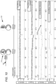
- Figure 9 illustrates torque and velocity with respect to the feed roller motor associated with the feed roller and the drive roller motor associated with the drive roller as media leaves the feed roller to illustrate operation of the apparatus 100.
- the drive roller 120 may be placed in constant velocity mode. That is, the velocity control module 130 may reduce the velocity 114 for the drive roller motor 118 to the high velocity threshold 136. Further, the velocity control module 130 may maintain the velocity 114 for the drive roller motor 118 at the high velocity threshold 136. At 902, the torque control module 128 may allow, during the maintenance of the velocity 114 for the drive roller motor 118 at the high velocity threshold 136, variations in the torque 116 for the drive roller motor 118.
- Figure 10 illustrates torque and velocity with respect to the feed roller motor associated with the feed roller and the drive roller motor associated with the drive roller at constant velocity before further media enters the feed roller to illustrate operation of the apparatus 100.
- the drive roller 120 may operate at constant velocity (e.g., at the high velocity threshold 136) before further media 122 enters the feed roller 110.
- Figures 11-13 respectively illustrate an example block diagram 1100, an example flowchart of a method 1200, and a further example block diagram 1300 for velocity and torque based media motor control.
- the block diagram 1100, the method 1200, and the block diagram 1300 may be implemented on the apparatus 100 described above with reference to Figure 1 by way of example and not limitation.
- the block diagram 1100, the method 1200, and the block diagram 1300 may be practiced in other apparatus.
- Figure 11 shows hardware of the apparatus 100 that may execute the instructions of the block diagram 1100.
- the hardware may include a processor 1102, and a memory 1104 (i.e., a non-transitory computer readable medium) storing machine readable instructions that when executed by the processor cause the processor to perform the instructions of the block diagram 1100.
- the memory 1104 may represent a non-transitory computer readable medium.
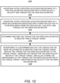
- Figure 12 may represent a method for velocity and torque based media motor control, and the steps of the method.
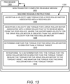
- Figure 13 may represent a non-transitory computer readable medium 1302 having stored thereon machine readable instructions to provide velocity and torque based media motor control.
- the machine readable instructions when executed, cause a processor 1304 to perform the instructions of the block diagram 1300 also shown in Figure 13 .
- the processor 1102 of Figure 11 and/or the processor 1304 of Figure 13 may include a single or multiple processors or other hardware processing circuit, to execute the methods, functions and other processes described herein. These methods, functions and other processes may be embodied as machine readable instructions stored on a computer readable medium, which may be non-transitory (e.g., the non-transitory computer readable medium 1302 of Figure 13 ), such as hardware storage devices (e.g., RAM (random access memory), ROM (read only memory), EPROM (erasable, programmable ROM), EEPROM (electrically erasable, programmable ROM), hard drives, and flash memory).
- the memory 1104 may include a RAM, where the machine readable instructions and data for a processor may reside during runtime.
- the memory 1104 may include instructions 1106 to ascertain a velocity 104 and a torque 106 for a feed roller motor 108 associated with (i.e., imparts motion of) a feed roller 110.
- the processor 1102 may fetch, decode, and execute the instructions 1108 to ascertain a velocity 114 and a torque 116 for a drive roller motor 118 associated with (i.e., imparts motion of) a drive roller 120 that is to receive media 122 from the feed roller 110.
- the method may include ascertaining, after a specified acceleration distance of a feed roller motor 108 associated with a feed roller 110, a velocity and torque for the feed roller motor 108.
- the method may include ascertaining, after a specified acceleration distance of a drive roller motor 118 associated with a drive roller 120 that is to receive media 122 from the feed roller 110, a velocity and torque for the drive roller motor 118.
- the method may include determining whether the torque 116 for the drive roller motor 118 is greater than a torque target 126.
- the method may include reducing the torque 116 for the drive roller motor 118 to the torque target 126, maintaining the torque 116 for the drive roller motor 118 at the torque target 126, and allowing, during the maintenance of the torque 116 for the drive roller motor 118 at the torque target 126, variations in the velocity 114 for the drive roller motor 118.
- the non-transitory computer readable medium 1302 may include instructions 1306 to ascertain a velocity 104 and a torque 106 for a feed roller motor 108 associated with (i.e., imparts motion of) a feed roller 110.
- the processor 1304 may fetch, decode, and execute the instructions 1308 to ascertain a velocity and torque for a drive roller motor 118 associated with a drive roller 120 that is to receive media 122 from the feed roller 110, where the ascertained velocity 114 for the drive roller motor 118 is greater than the ascertained velocity 104 for the feed roller motor 108.
- the processor 1304 may fetch, decode, and execute the instructions 1310 to determine whether the torque 116 for the drive roller motor 118 is greater than a torque target 126.
- the processor 1304 may fetch, decode, and execute the instructions 1312 to reduce the torque 116 for the drive roller motor 118 to the torque target 126, and maintain the torque 116 for the drive roller motor 118 at the torque target 126.
Landscapes
- Engineering & Computer Science (AREA)
- Mechanical Engineering (AREA)
- Delivering By Means Of Belts And Rollers (AREA)
- Handling Of Sheets (AREA)
- Sheets, Magazines, And Separation Thereof (AREA)
- Control Of Electric Motors In General (AREA)
Claims (15)
- Appareil (100) comprenant :un module de détermination de vitesse et de couple d'un moteur de rouleau d'alimentation (102) configuré pour vérifier une vitesse et un couple d'un moteur de rouleau d'alimentation (106) associé à un rouleau d'alimentation (110) ;un module de détermination de vitesse et de couple d'un moteur de rouleau d'entraînement (112) configuré pour vérifier une vitesse et un couple d'un moteur de rouleau d'entraînement (118) associé à un rouleau d'entraînement (120) qui doit recevoir un support à partir du rouleau d'alimentation ;un module de commande de couple (128) configuré pour réduire le couple du moteur du rouleau d'entraînement jusqu'au couple cible, et pour maintenir le couple du moteur du rouleau d'entraînement au niveau du couple cible ; etun module de commande de vitesse (130) configuré pour permettre, pendant le maintien du couple du moteur du rouleau d'entraînement au niveau de la cible de couple, des variations dans la vitesse du moteur du rouleau d'entraînement ;un processeur (1102) ; etun support non transitoire lisible par ordinateur stockant des instructions lisibles par machine (1100) qui, lorsqu'elles sont exécutées :amènent le module de détermination de vitesse et de couple d'un moteur de rouleau d'alimentation (102) à vérifier (1106) la vitesse et le couple du moteur du rouleau d'alimentation associé au rouleau d'alimentation ;amènent le module de détermination de vitesse et de couple d'un moteur de rouleau d'entraînement (112) à vérifier (1108) la vitesse et le couple du moteur du rouleau d'entraînement associé au rouleau d'entraînement ;amènent le processeur (1102) à déterminer (1110) si le couple du moteur du rouleau d'entraînement est supérieur à un couple cible ; eten réponse (1112) à la détermination que le couple du moteur du rouleau d'entraînement est supérieur au couple cible ;amènent le module de commande du couple (128) à réduire le couple du moteur du rouleau d'entraînement jusqu'au couple cible et à maintenir le couple du moteur du rouleau d'entraînement au niveau du couple cible ; etamènent le module de commande de vitesse (130) à permettre, pendant le maintien du couple du moteur du rouleau d'entraînement au niveau de la cible de couple, des variations dans la vitesse du moteur du rouleau d'entraînement.
- Appareil (100) selon la revendication 1, dans lequel le support comporte du papier.
- Appareil (100) selon la revendication 1, dans lequel les instructions (1100), lorsqu'elles sont exécutées par le processeur, doivent en outre amener le processeur à :
amener le module de détermination de vitesse et de couple d'un moteur de rouleau d'entraînement (102) à vérifier (1204), après une distance d'accélération spécifiée du moteur du rouleau d'entraînement, la vitesse et le couple du moteur du rouleau d'entraînement associé au rouleau d'entraînement qui doit recevoir un support à partir du rouleau d'alimentation. - Appareil (100) selon la revendication 1, dans lequel les instructions (1100), lorsqu'elles sont exécutées par le processeur, doivent en outre amener le processeur à :déterminer si la vitesse du moteur du rouleau d'entraînement associé au rouleau d'entraînement est inférieure à un seuil de faible vitesse ; et,en réponse à la détermination que la vitesse du moteur du rouleau d'entraînement associé au rouleau d'entraînement est inférieure au seuil de faible vitesse, générer une indication de décrochage du moteur du rouleau d'entraînement.
- Appareil (100) selon la revendication 4, dans lequel les instructions (1100), lorsqu'elles sont exécutées par le processeur, doivent en outre amener le processeur à :déterminer si la vitesse du moteur du rouleau d'entraînement associé au rouleau d'entraînement est supérieure à un seuil de grande vitesse ; et,en réponse à une détermination que la vitesse du moteur du rouleau d'entraînement associé au rouleau d'entraînement est supérieure au seuil de grande vitesse :réduire, par le module de commande de vitesse (130), la vitesse du moteur du rouleau d'entraînement jusqu'au seuil de grande vitesse, etmaintenir, par le module de commande de vitesse (130), la vitesse du moteur du rouleau d'entraînement au niveau du seuil de grande vitesse, etpermettre, par le module de commande de couple (128), pendant le maintien de la vitesse du moteur du rouleau d'entraînement au niveau du seuil de grande vitesse, des variations dans le couple du moteur du rouleau d'entraînement.
- Appareil (100) selon la revendication 1, dans lequel la vitesse constatée pour le moteur du rouleau d'entraînement associé au rouleau d'entraînement est supérieure à la vitesse constatée pour le moteur du rouleau d'alimentation associé au rouleau d'alimentation.
- Procédé mis en oeuvre par ordinateur (1200), comprenant :la vérification (1202), par un module de détermination de vitesse et de couple d'un moteur de rouleau d'alimentation, après une distance d'accélération spécifiée d'un moteur de rouleau d'alimentation associé à un rouleau d'alimentation, d'une vitesse et d'un couple du moteur du rouleau d'alimentation ;la vérification (1204), par un module de détermination de vitesse et de couple d'un moteur de rouleau d'entraînement, après une distance d'accélération spécifiée d'un moteur de rouleau d'entraînement associé à un rouleau d'entraînement qui doit recevoir un support à partir du rouleau d'alimentation, d'une vitesse et d'un couple du moteur du rouleau d'entraînement ;le fait de déterminer (1206), par un processeur, si le couple du moteur du rouleau d'entraînement est supérieur à un couple cible ; eten réponse à la détermination que le couple du moteur du rouleau d'entraînement est supérieur à la cible de couple,la réduction, par un module de commande de couple, du couple du moteur du rouleau d'entraînement jusqu'à la cible de couple,le maintien, par le module de commande de couple, du couple du moteur du rouleau d'entraînement au niveau de la cible de couple, etle fait de permettre, par un module de commande de vitesse, pendant le maintien du couple du moteur du rouleau d'entraînement au niveau de la cible de couple, des variations dans la vitesse du moteur du rouleau d'entraînement.
- Procédé selon la revendication 7, dans lequel le support comporte du papier.
- Procédé selon la revendication 7, comprenant en outre :le fait de déterminer si la vitesse du moteur du rouleau d'entraînement associé au rouleau d'entraînement est inférieure à un seuil de faible vitesse ; eten réponse à la détermination que la vitesse du moteur du rouleau d'entraînement associé au rouleau d'entraînement est inférieure au seuil de faible vitesse, la génération, par le module de commande de vitesse, d'une indication de décrochage du moteur du rouleau d'entraînement.
- Procédé selon la revendication 9, comprenant en outre :le fait de déterminer si la vitesse du moteur du rouleau d'entraînement associé au rouleau d'entraînement est supérieure à un seuil de grande vitesse ; eten réponse à une détermination que la vitesse du moteur du rouleau d'entraînement associé au rouleau d'entraînement est supérieure au seuil de grande vitesse,la réduction, par le module de commande de vitesse, de la vitesse du moteur du rouleau d'entraînement jusqu'au seuil de grande vitesse,le maintien, par le module de commande de vitesse, de la vitesse du moteur du rouleau d'entraînement au niveau du seuil de grande vitesse, etle fait de permettre, par le module de commande de couple, pendant le maintien de la vitesse du moteur du rouleau d'entraînement au niveau du seuil de grande vitesse, des variations dans le couple du moteur du rouleau d'entraînement.
- Procédé selon la revendication 7, dans lequel la vitesse constatée du moteur du rouleau d'entraînement associé au rouleau d'entraînement est supérieure à la vitesse constatée du moteur du rouleau d'alimentation associé au rouleau d'alimentation.
- Support non transitoire lisible par ordinateur sur lequel sont stockées des instructions (1100) lisibles par machine, les instructions lisibles par machine, lorsqu'elles sont exécutées, amènent un processeur à :amener un module de détermination de vitesse et de couple d'un moteur de rouleau d'alimentation à vérifier (1106) une vitesse et un couple d'un moteur de rouleau d'alimentation associé à un rouleau d'alimentation ;amener un module de détermination de vitesse et de couple d'un moteur d'entraînement à vérifier (1108) une vitesse et un couple d'un moteur de rouleau d'entraînement associé à un rouleau d'entraînement qui doit recevoir un support à partir du rouleau d'alimentation, dans lequel la vitesse constatée du moteur du rouleau d'entraînement est supérieure à la vitesse constatée du moteur du rouleau d'alimentation ;déterminer (1110) si le couple du moteur du rouleau d'entraînement est supérieur à un couple cible ; eten réponse (1112) à une détermination que le couple du moteur du rouleau d'entraînement est supérieur au couple cible,amener un module de commande de couple à réduire le couple du moteur du rouleau d'entraînement jusqu'à la cible de couple, etmaintenir le couple du moteur du rouleau d'entraînement au niveau de la cible de couple.
- Support non transitoire lisible par ordinateur selon la revendication 12, dans lequel les instructions lisibles par machine (1100), lorsqu'elles sont exécutées, amènent en outre le processeur à :
amener un module de commande de vitesse à permettre, pendant le maintien du couple du moteur du rouleau d'entraînement au niveau de la cible de couple, des variations dans la vitesse du moteur du rouleau d'entraînement. - Support non transitoire lisible par ordinateur selon la revendication 12, dans lequel les instructions lisibles par machine (1110), lorsqu'elles sont exécutées, amènent en outre le processeur à :déterminer si la vitesse du moteur du rouleau d'entraînement associé au rouleau d'entraînement est inférieure à un seuil de faible vitesse ; eten réponse à une détermination que la vitesse du moteur du rouleau d'entraînement associé au rouleau d'entraînement est inférieure au seuil de faible vitesse, amener le module de commande de vitesse à générer une indication de décrochage du moteur du rouleau d'entraînement.
- Support non transitoire lisible par ordinateur selon la revendication 14, dans lequel les instructions lisibles par machine (1110), lorsqu'elles sont exécutées, amènent en outre le processeur à :déterminer si la vitesse du moteur du rouleau d'entraînement associé au rouleau d'entraînement est supérieure à un seuil de grande vitesse ; eten réponse à une détermination que la vitesse du moteur du rouleau d'entraînement associé au rouleau d'entraînement est supérieure au seuil de grande vitesse, amener le module de commande de vitesse àréduire la vitesse du moteur du rouleau d'entraînement au seuil de grande vitesse,maintenir la vitesse du moteur du rouleau d'entraînement au niveau du seuil de grande vitesse, etamener le module de commande de couple à permettre, pendant le maintien de la vitesse du moteur du rouleau d'entraînement au niveau du seuil de grande vitesse, des variations dans le couple du moteur du rouleau d'entraînement.
Applications Claiming Priority (1)
| Application Number | Priority Date | Filing Date | Title |
|---|---|---|---|
| PCT/US2017/054971 WO2019070245A1 (fr) | 2017-10-03 | 2017-10-03 | Commande de moteur de support sur la base de la vitesse et du couple |
Publications (3)
| Publication Number | Publication Date |
|---|---|
| EP3691908A1 EP3691908A1 (fr) | 2020-08-12 |
| EP3691908A4 EP3691908A4 (fr) | 2021-04-28 |
| EP3691908B1 true EP3691908B1 (fr) | 2024-08-21 |
Family
ID=65995276
Family Applications (1)
| Application Number | Title | Priority Date | Filing Date |
|---|---|---|---|
| EP17927982.3A Active EP3691908B1 (fr) | 2017-10-03 | 2017-10-03 | Commande de moteur de support sur la base de la vitesse et du couple |
Country Status (4)
| Country | Link |
|---|---|
| US (1) | US10947073B2 (fr) |
| EP (1) | EP3691908B1 (fr) |
| CN (1) | CN111225800B (fr) |
| WO (1) | WO2019070245A1 (fr) |
Families Citing this family (1)
| Publication number | Priority date | Publication date | Assignee | Title |
|---|---|---|---|---|
| KR20210116744A (ko) * | 2020-03-13 | 2021-09-28 | 휴렛-팩커드 디벨롭먼트 컴퍼니, 엘.피. | 부하 토크가 작용하는 롤러의 구동력을 보완하기 위한 구조 |
Family Cites Families (19)
| Publication number | Priority date | Publication date | Assignee | Title |
|---|---|---|---|---|
| JP2965463B2 (ja) * | 1994-07-04 | 1999-10-18 | シャープ株式会社 | インクシート搬送制御装置 |
| JP3762071B2 (ja) | 1997-11-04 | 2006-03-29 | 三菱重工業株式会社 | 印刷開始時におけるウェブ送り出し走行制御方法及び装置 |
| US6607321B2 (en) * | 2000-11-29 | 2003-08-19 | Xerox Corporation | Method and apparatus for moving a medium through a medium indexing device |
| JP3809406B2 (ja) * | 2002-08-29 | 2006-08-16 | キヤノン株式会社 | 記録装置及び記録装置の制御方法 |
| JP2007153560A (ja) * | 2005-12-06 | 2007-06-21 | Fuji Xerox Co Ltd | 給紙装置および画像形成装置 |
| KR20080065106A (ko) * | 2007-01-08 | 2008-07-11 | 삼성전자주식회사 | 화상 형성 장치 |
| US8159159B2 (en) * | 2007-11-27 | 2012-04-17 | Hewlett-Packard Development Company, L.P. | Controlling tension in roll-based print media |
| US7931274B2 (en) | 2009-05-29 | 2011-04-26 | Xerox Corporation | Hybrid control of sheet transport modules |
| US20130066064A1 (en) | 2010-05-20 | 2013-03-14 | Glaxosmithkline Biologicals S.A, | Novel process |
| US8020864B1 (en) | 2010-05-27 | 2011-09-20 | Xerox Corporation | Printing system and method using alternating velocity and torque control modes for operating one or more select sheet transport devices to avoid contention |
| JP5724280B2 (ja) * | 2010-10-06 | 2015-05-27 | セイコーエプソン株式会社 | プリンター、及び、印刷方法 |
| JP5921254B2 (ja) * | 2011-04-15 | 2016-05-24 | キヤノン株式会社 | 記録装置、搬送装置、及び搬送制御方法 |
| JP5990884B2 (ja) * | 2011-09-16 | 2016-09-14 | ブラザー工業株式会社 | モータ制御装置及び画像形成装置 |
| JP5847534B2 (ja) * | 2011-10-21 | 2016-01-27 | キヤノン株式会社 | シート搬送装置、プリント装置およびジャム処理方法 |
| JP5817470B2 (ja) * | 2011-11-25 | 2015-11-18 | セイコーエプソン株式会社 | 画像記録装置、画像記録方法 |
| JP2013209220A (ja) * | 2012-03-01 | 2013-10-10 | Ricoh Co Ltd | 媒体搬送装置、画像形成装置及び媒体搬送システム |
| JP5905306B2 (ja) * | 2012-03-19 | 2016-04-20 | 株式会社Pfu | 媒体供給装置 |
| JP6091248B2 (ja) * | 2013-02-22 | 2017-03-08 | キヤノン株式会社 | プリンタ |
| JP6394089B2 (ja) * | 2014-06-13 | 2018-09-26 | 株式会社リコー | 分離搬送装置、分離搬送装置の制御方法および制御プログラム、ならびに、画像形成装置 |
-
2017
- 2017-10-03 US US16/651,197 patent/US10947073B2/en active Active
- 2017-10-03 CN CN201780095514.1A patent/CN111225800B/zh active Active
- 2017-10-03 WO PCT/US2017/054971 patent/WO2019070245A1/fr not_active Ceased
- 2017-10-03 EP EP17927982.3A patent/EP3691908B1/fr active Active
Also Published As
| Publication number | Publication date |
|---|---|
| EP3691908A1 (fr) | 2020-08-12 |
| US20200270081A1 (en) | 2020-08-27 |
| CN111225800B (zh) | 2022-04-15 |
| WO2019070245A1 (fr) | 2019-04-11 |
| EP3691908A4 (fr) | 2021-04-28 |
| CN111225800A (zh) | 2020-06-02 |
| US10947073B2 (en) | 2021-03-16 |
Similar Documents
| Publication | Publication Date | Title |
|---|---|---|
| US9334137B2 (en) | Roll sheet conveying apparatus and sheet conveying control method | |
| RU2016120849A (ru) | Управление производительностью горнодобывающей системы | |
| EP3691908B1 (fr) | Commande de moteur de support sur la base de la vitesse et du couple | |
| US20160079897A1 (en) | Motor drive control device, motor drive control method, and non-transitory computer-readable medium | |
| JP2016026917A5 (fr) | ||
| JP2018153928A5 (fr) | ||
| CN102959216A (zh) | 船舶的引擎控制装置及方法 | |
| EP3218199B1 (fr) | Génération de tampon progressive | |
| EP2767403B1 (fr) | Dispositif de transport et appareil d'impression à jet d'encre ayant le même | |
| US10935959B2 (en) | Motor control device, control system, and motor control method | |
| JP2015030229A5 (fr) | ||
| CN107073980B (zh) | 打印介质排出 | |
| JP2016199395A (ja) | 記録装置、記録装置の制御方法及び搬送装置 | |
| CN116512781A (zh) | 一种腕带打印机的变速打印方法及腕带打印机 | |
| EP3509846B1 (fr) | Mode de débit réduit de système d'impression | |
| JP2007041370A (ja) | 画像形成装置 | |
| US9757965B1 (en) | Printing device performance analysis | |
| CN106061874B (zh) | 旋转模式生成装置及旋转模式生成方法 | |
| JP2015150775A (ja) | 印刷装置、制御方法、及び制御プログラム | |
| KR102169761B1 (ko) | 인쇄 영역 조정 | |
| JP2013199338A5 (ja) | 搬送装置及び記録装置 | |
| US9744782B1 (en) | Printing device performance management | |
| JP2018095358A (ja) | 後処理装置及び制御方法 | |
| JP2017024845A (ja) | シート状媒体搬送装置、画像形成装置、および制御方法 | |
| JP2006203986A (ja) | モータ駆動制御装置およびモータ駆動制御方法および画像形成装置 |
Legal Events
| Date | Code | Title | Description |
|---|---|---|---|
| STAA | Information on the status of an ep patent application or granted ep patent |
Free format text: STATUS: THE INTERNATIONAL PUBLICATION HAS BEEN MADE |
|
| PUAI | Public reference made under article 153(3) epc to a published international application that has entered the european phase |
Free format text: ORIGINAL CODE: 0009012 |
|
| STAA | Information on the status of an ep patent application or granted ep patent |
Free format text: STATUS: REQUEST FOR EXAMINATION WAS MADE |
|
| 17P | Request for examination filed |
Effective date: 20200325 |
|
| AK | Designated contracting states |
Kind code of ref document: A1 Designated state(s): AL AT BE BG CH CY CZ DE DK EE ES FI FR GB GR HR HU IE IS IT LI LT LU LV MC MK MT NL NO PL PT RO RS SE SI SK SM TR |
|
| AX | Request for extension of the european patent |
Extension state: BA ME |
|
| DAV | Request for validation of the european patent (deleted) | ||
| DAX | Request for extension of the european patent (deleted) | ||
| A4 | Supplementary search report drawn up and despatched |
Effective date: 20210325 |
|
| RIC1 | Information provided on ipc code assigned before grant |
Ipc: B41J 11/42 20060101ALI20210319BHEP Ipc: B65H 43/00 20060101ALI20210319BHEP Ipc: B65H 29/12 20060101ALI20210319BHEP Ipc: B65H 7/02 20060101ALI20210319BHEP Ipc: B65H 5/06 20060101ALI20210319BHEP Ipc: B41J 29/38 20060101ALI20210319BHEP Ipc: B41J 13/03 20060101AFI20210319BHEP |
|
| STAA | Information on the status of an ep patent application or granted ep patent |
Free format text: STATUS: EXAMINATION IS IN PROGRESS |
|
| 17Q | First examination report despatched |
Effective date: 20220822 |
|
| GRAP | Despatch of communication of intention to grant a patent |
Free format text: ORIGINAL CODE: EPIDOSNIGR1 |
|
| GRAP | Despatch of communication of intention to grant a patent |
Free format text: ORIGINAL CODE: EPIDOSNIGR1 |
|
| STAA | Information on the status of an ep patent application or granted ep patent |
Free format text: STATUS: GRANT OF PATENT IS INTENDED |
|
| INTG | Intention to grant announced |
Effective date: 20240614 |
|
| GRAS | Grant fee paid |
Free format text: ORIGINAL CODE: EPIDOSNIGR3 |
|
| GRAA | (expected) grant |
Free format text: ORIGINAL CODE: 0009210 |
|
| STAA | Information on the status of an ep patent application or granted ep patent |
Free format text: STATUS: THE PATENT HAS BEEN GRANTED |
|
| AK | Designated contracting states |
Kind code of ref document: B1 Designated state(s): AL AT BE BG CH CY CZ DE DK EE ES FI FR GB GR HR HU IE IS IT LI LT LU LV MC MK MT NL NO PL PT RO RS SE SI SK SM TR |
|
| REG | Reference to a national code |
Ref country code: GB Ref legal event code: FG4D |
|
| REG | Reference to a national code |
Ref country code: CH Ref legal event code: EP |
|
| REG | Reference to a national code |
Ref country code: DE Ref legal event code: R096 Ref document number: 602017084353 Country of ref document: DE |
|
| REG | Reference to a national code |
Ref country code: IE Ref legal event code: FG4D |
|
| REG | Reference to a national code |
Ref country code: LT Ref legal event code: MG9D |
|
| REG | Reference to a national code |
Ref country code: NL Ref legal event code: MP Effective date: 20240821 |
|
| PG25 | Lapsed in a contracting state [announced via postgrant information from national office to epo] |
Ref country code: NO Free format text: LAPSE BECAUSE OF FAILURE TO SUBMIT A TRANSLATION OF THE DESCRIPTION OR TO PAY THE FEE WITHIN THE PRESCRIBED TIME-LIMIT Effective date: 20241121 |
|
| REG | Reference to a national code |
Ref country code: AT Ref legal event code: MK05 Ref document number: 1715183 Country of ref document: AT Kind code of ref document: T Effective date: 20240821 |
|
| PG25 | Lapsed in a contracting state [announced via postgrant information from national office to epo] |
Ref country code: FI Free format text: LAPSE BECAUSE OF FAILURE TO SUBMIT A TRANSLATION OF THE DESCRIPTION OR TO PAY THE FEE WITHIN THE PRESCRIBED TIME-LIMIT Effective date: 20240821 Ref country code: NL Free format text: LAPSE BECAUSE OF FAILURE TO SUBMIT A TRANSLATION OF THE DESCRIPTION OR TO PAY THE FEE WITHIN THE PRESCRIBED TIME-LIMIT Effective date: 20240821 Ref country code: GR Free format text: LAPSE BECAUSE OF FAILURE TO SUBMIT A TRANSLATION OF THE DESCRIPTION OR TO PAY THE FEE WITHIN THE PRESCRIBED TIME-LIMIT Effective date: 20241122 Ref country code: PL Free format text: LAPSE BECAUSE OF FAILURE TO SUBMIT A TRANSLATION OF THE DESCRIPTION OR TO PAY THE FEE WITHIN THE PRESCRIBED TIME-LIMIT Effective date: 20240821 Ref country code: PT Free format text: LAPSE BECAUSE OF FAILURE TO SUBMIT A TRANSLATION OF THE DESCRIPTION OR TO PAY THE FEE WITHIN THE PRESCRIBED TIME-LIMIT Effective date: 20241223 |
|
| PG25 | Lapsed in a contracting state [announced via postgrant information from national office to epo] |
Ref country code: BG Free format text: LAPSE BECAUSE OF FAILURE TO SUBMIT A TRANSLATION OF THE DESCRIPTION OR TO PAY THE FEE WITHIN THE PRESCRIBED TIME-LIMIT Effective date: 20240821 |
|
| PG25 | Lapsed in a contracting state [announced via postgrant information from national office to epo] |
Ref country code: LV Free format text: LAPSE BECAUSE OF FAILURE TO SUBMIT A TRANSLATION OF THE DESCRIPTION OR TO PAY THE FEE WITHIN THE PRESCRIBED TIME-LIMIT Effective date: 20240821 |
|
| PG25 | Lapsed in a contracting state [announced via postgrant information from national office to epo] |
Ref country code: IS Free format text: LAPSE BECAUSE OF FAILURE TO SUBMIT A TRANSLATION OF THE DESCRIPTION OR TO PAY THE FEE WITHIN THE PRESCRIBED TIME-LIMIT Effective date: 20241221 Ref country code: AT Free format text: LAPSE BECAUSE OF FAILURE TO SUBMIT A TRANSLATION OF THE DESCRIPTION OR TO PAY THE FEE WITHIN THE PRESCRIBED TIME-LIMIT Effective date: 20240821 |
|
| PG25 | Lapsed in a contracting state [announced via postgrant information from national office to epo] |
Ref country code: HR Free format text: LAPSE BECAUSE OF FAILURE TO SUBMIT A TRANSLATION OF THE DESCRIPTION OR TO PAY THE FEE WITHIN THE PRESCRIBED TIME-LIMIT Effective date: 20240821 |
|
| PG25 | Lapsed in a contracting state [announced via postgrant information from national office to epo] |
Ref country code: ES Free format text: LAPSE BECAUSE OF FAILURE TO SUBMIT A TRANSLATION OF THE DESCRIPTION OR TO PAY THE FEE WITHIN THE PRESCRIBED TIME-LIMIT Effective date: 20240821 Ref country code: RS Free format text: LAPSE BECAUSE OF FAILURE TO SUBMIT A TRANSLATION OF THE DESCRIPTION OR TO PAY THE FEE WITHIN THE PRESCRIBED TIME-LIMIT Effective date: 20241121 |
|
| PG25 | Lapsed in a contracting state [announced via postgrant information from national office to epo] |
Ref country code: RS Free format text: LAPSE BECAUSE OF FAILURE TO SUBMIT A TRANSLATION OF THE DESCRIPTION OR TO PAY THE FEE WITHIN THE PRESCRIBED TIME-LIMIT Effective date: 20241121 Ref country code: PT Free format text: LAPSE BECAUSE OF FAILURE TO SUBMIT A TRANSLATION OF THE DESCRIPTION OR TO PAY THE FEE WITHIN THE PRESCRIBED TIME-LIMIT Effective date: 20241223 Ref country code: PL Free format text: LAPSE BECAUSE OF FAILURE TO SUBMIT A TRANSLATION OF THE DESCRIPTION OR TO PAY THE FEE WITHIN THE PRESCRIBED TIME-LIMIT Effective date: 20240821 Ref country code: NO Free format text: LAPSE BECAUSE OF FAILURE TO SUBMIT A TRANSLATION OF THE DESCRIPTION OR TO PAY THE FEE WITHIN THE PRESCRIBED TIME-LIMIT Effective date: 20241121 Ref country code: NL Free format text: LAPSE BECAUSE OF FAILURE TO SUBMIT A TRANSLATION OF THE DESCRIPTION OR TO PAY THE FEE WITHIN THE PRESCRIBED TIME-LIMIT Effective date: 20240821 Ref country code: LV Free format text: LAPSE BECAUSE OF FAILURE TO SUBMIT A TRANSLATION OF THE DESCRIPTION OR TO PAY THE FEE WITHIN THE PRESCRIBED TIME-LIMIT Effective date: 20240821 Ref country code: IS Free format text: LAPSE BECAUSE OF FAILURE TO SUBMIT A TRANSLATION OF THE DESCRIPTION OR TO PAY THE FEE WITHIN THE PRESCRIBED TIME-LIMIT Effective date: 20241221 Ref country code: HR Free format text: LAPSE BECAUSE OF FAILURE TO SUBMIT A TRANSLATION OF THE DESCRIPTION OR TO PAY THE FEE WITHIN THE PRESCRIBED TIME-LIMIT Effective date: 20240821 Ref country code: GR Free format text: LAPSE BECAUSE OF FAILURE TO SUBMIT A TRANSLATION OF THE DESCRIPTION OR TO PAY THE FEE WITHIN THE PRESCRIBED TIME-LIMIT Effective date: 20241122 Ref country code: FI Free format text: LAPSE BECAUSE OF FAILURE TO SUBMIT A TRANSLATION OF THE DESCRIPTION OR TO PAY THE FEE WITHIN THE PRESCRIBED TIME-LIMIT Effective date: 20240821 Ref country code: ES Free format text: LAPSE BECAUSE OF FAILURE TO SUBMIT A TRANSLATION OF THE DESCRIPTION OR TO PAY THE FEE WITHIN THE PRESCRIBED TIME-LIMIT Effective date: 20240821 Ref country code: BG Free format text: LAPSE BECAUSE OF FAILURE TO SUBMIT A TRANSLATION OF THE DESCRIPTION OR TO PAY THE FEE WITHIN THE PRESCRIBED TIME-LIMIT Effective date: 20240821 Ref country code: AT Free format text: LAPSE BECAUSE OF FAILURE TO SUBMIT A TRANSLATION OF THE DESCRIPTION OR TO PAY THE FEE WITHIN THE PRESCRIBED TIME-LIMIT Effective date: 20240821 |
|
| PG25 | Lapsed in a contracting state [announced via postgrant information from national office to epo] |
Ref country code: DK Free format text: LAPSE BECAUSE OF FAILURE TO SUBMIT A TRANSLATION OF THE DESCRIPTION OR TO PAY THE FEE WITHIN THE PRESCRIBED TIME-LIMIT Effective date: 20240821 Ref country code: SM Free format text: LAPSE BECAUSE OF FAILURE TO SUBMIT A TRANSLATION OF THE DESCRIPTION OR TO PAY THE FEE WITHIN THE PRESCRIBED TIME-LIMIT Effective date: 20240821 Ref country code: RO Free format text: LAPSE BECAUSE OF FAILURE TO SUBMIT A TRANSLATION OF THE DESCRIPTION OR TO PAY THE FEE WITHIN THE PRESCRIBED TIME-LIMIT Effective date: 20240821 |
|
| PG25 | Lapsed in a contracting state [announced via postgrant information from national office to epo] |
Ref country code: EE Free format text: LAPSE BECAUSE OF FAILURE TO SUBMIT A TRANSLATION OF THE DESCRIPTION OR TO PAY THE FEE WITHIN THE PRESCRIBED TIME-LIMIT Effective date: 20240821 |
|
| PG25 | Lapsed in a contracting state [announced via postgrant information from national office to epo] |
Ref country code: CZ Free format text: LAPSE BECAUSE OF FAILURE TO SUBMIT A TRANSLATION OF THE DESCRIPTION OR TO PAY THE FEE WITHIN THE PRESCRIBED TIME-LIMIT Effective date: 20240821 |
|
| PG25 | Lapsed in a contracting state [announced via postgrant information from national office to epo] |
Ref country code: SK Free format text: LAPSE BECAUSE OF FAILURE TO SUBMIT A TRANSLATION OF THE DESCRIPTION OR TO PAY THE FEE WITHIN THE PRESCRIBED TIME-LIMIT Effective date: 20240821 Ref country code: IT Free format text: LAPSE BECAUSE OF FAILURE TO SUBMIT A TRANSLATION OF THE DESCRIPTION OR TO PAY THE FEE WITHIN THE PRESCRIBED TIME-LIMIT Effective date: 20240821 |
|
| REG | Reference to a national code |
Ref country code: DE Ref legal event code: R097 Ref document number: 602017084353 Country of ref document: DE |
|
| REG | Reference to a national code |
Ref country code: CH Ref legal event code: PL |
|
| PLBE | No opposition filed within time limit |
Free format text: ORIGINAL CODE: 0009261 |
|
| STAA | Information on the status of an ep patent application or granted ep patent |
Free format text: STATUS: NO OPPOSITION FILED WITHIN TIME LIMIT |
|
| PG25 | Lapsed in a contracting state [announced via postgrant information from national office to epo] |
Ref country code: MC Free format text: LAPSE BECAUSE OF FAILURE TO SUBMIT A TRANSLATION OF THE DESCRIPTION OR TO PAY THE FEE WITHIN THE PRESCRIBED TIME-LIMIT Effective date: 20240821 |
|
| PG25 | Lapsed in a contracting state [announced via postgrant information from national office to epo] |
Ref country code: LU Free format text: LAPSE BECAUSE OF NON-PAYMENT OF DUE FEES Effective date: 20241003 Ref country code: BE Free format text: LAPSE BECAUSE OF NON-PAYMENT OF DUE FEES Effective date: 20241031 |
|
| PG25 | Lapsed in a contracting state [announced via postgrant information from national office to epo] |
Ref country code: FR Free format text: LAPSE BECAUSE OF NON-PAYMENT OF DUE FEES Effective date: 20241021 |
|
| GBPC | Gb: european patent ceased through non-payment of renewal fee |
Effective date: 20241121 |
|
| PG25 | Lapsed in a contracting state [announced via postgrant information from national office to epo] |
Ref country code: CH Free format text: LAPSE BECAUSE OF NON-PAYMENT OF DUE FEES Effective date: 20241031 |
|
| 26N | No opposition filed |
Effective date: 20250522 |
|
| REG | Reference to a national code |
Ref country code: BE Ref legal event code: MM Effective date: 20241031 |
|
| PG25 | Lapsed in a contracting state [announced via postgrant information from national office to epo] |
Ref country code: SE Free format text: LAPSE BECAUSE OF FAILURE TO SUBMIT A TRANSLATION OF THE DESCRIPTION OR TO PAY THE FEE WITHIN THE PRESCRIBED TIME-LIMIT Effective date: 20240821 |
|
| PG25 | Lapsed in a contracting state [announced via postgrant information from national office to epo] |
Ref country code: GB Free format text: LAPSE BECAUSE OF NON-PAYMENT OF DUE FEES Effective date: 20241121 |
|
| PG25 | Lapsed in a contracting state [announced via postgrant information from national office to epo] |
Ref country code: IE Free format text: LAPSE BECAUSE OF NON-PAYMENT OF DUE FEES Effective date: 20241003 |
|
| PGFP | Annual fee paid to national office [announced via postgrant information from national office to epo] |
Ref country code: DE Payment date: 20250923 Year of fee payment: 9 |
|
| PG25 | Lapsed in a contracting state [announced via postgrant information from national office to epo] |
Ref country code: CY Free format text: LAPSE BECAUSE OF FAILURE TO SUBMIT A TRANSLATION OF THE DESCRIPTION OR TO PAY THE FEE WITHIN THE PRESCRIBED TIME-LIMIT; INVALID AB INITIO Effective date: 20171003 |
|
| PG25 | Lapsed in a contracting state [announced via postgrant information from national office to epo] |
Ref country code: HU Free format text: LAPSE BECAUSE OF FAILURE TO SUBMIT A TRANSLATION OF THE DESCRIPTION OR TO PAY THE FEE WITHIN THE PRESCRIBED TIME-LIMIT; INVALID AB INITIO Effective date: 20171003 |