EP3689293B1 - Pflegeeinheit - Google Patents
Pflegeeinheit Download PDFInfo
- Publication number
- EP3689293B1 EP3689293B1 EP20152211.7A EP20152211A EP3689293B1 EP 3689293 B1 EP3689293 B1 EP 3689293B1 EP 20152211 A EP20152211 A EP 20152211A EP 3689293 B1 EP3689293 B1 EP 3689293B1
- Authority
- EP
- European Patent Office
- Prior art keywords
- terminal
- cover
- charging stand
- care apparatus
- care
- Prior art date
- Legal status (The legal status is an assumption and is not a legal conclusion. Google has not performed a legal analysis and makes no representation as to the accuracy of the status listed.)
- Active
Links
Images


Classifications
-
- A—HUMAN NECESSITIES
- A61—MEDICAL OR VETERINARY SCIENCE; HYGIENE
- A61C—DENTISTRY; APPARATUS OR METHODS FOR ORAL OR DENTAL HYGIENE
- A61C17/00—Devices for cleaning, polishing, rinsing or drying teeth, teeth cavities or prostheses; Saliva removers; Dental appliances for receiving spittle
- A61C17/16—Power-driven cleaning or polishing devices
- A61C17/22—Power-driven cleaning or polishing devices with brushes, cushions, cups, or the like
- A61C17/224—Electrical recharging arrangements
-
- H—ELECTRICITY
- H01—ELECTRIC ELEMENTS
- H01R—ELECTRICALLY-CONDUCTIVE CONNECTIONS; STRUCTURAL ASSOCIATIONS OF A PLURALITY OF MUTUALLY-INSULATED ELECTRICAL CONNECTING ELEMENTS; COUPLING DEVICES; CURRENT COLLECTORS
- H01R33/00—Coupling devices specially adapted for supporting apparatus and having one part acting as a holder providing support and electrical connection via a counterpart which is structurally associated with the apparatus, e.g. lamp holders; Separate parts thereof
- H01R33/05—Two-pole devices
- H01R33/06—Two-pole devices with two current-carrying pins, blades or analogous contacts, having their axes parallel to each other
-
- A—HUMAN NECESSITIES
- A61—MEDICAL OR VETERINARY SCIENCE; HYGIENE
- A61C—DENTISTRY; APPARATUS OR METHODS FOR ORAL OR DENTAL HYGIENE
- A61C17/00—Devices for cleaning, polishing, rinsing or drying teeth, teeth cavities or prostheses; Saliva removers; Dental appliances for receiving spittle
- A61C17/02—Rinsing or air-blowing devices, e.g. using fluid jets or comprising liquid medication
-
- H—ELECTRICITY
- H01—ELECTRIC ELEMENTS
- H01R—ELECTRICALLY-CONDUCTIVE CONNECTIONS; STRUCTURAL ASSOCIATIONS OF A PLURALITY OF MUTUALLY-INSULATED ELECTRICAL CONNECTING ELEMENTS; COUPLING DEVICES; CURRENT COLLECTORS
- H01R13/00—Details of coupling devices of the kinds covered by groups H01R12/70 or H01R24/00 - H01R33/00
- H01R13/02—Contact members
- H01R13/26—Pin or blade contacts for sliding co-operation on one side only
-
- H—ELECTRICITY
- H01—ELECTRIC ELEMENTS
- H01R—ELECTRICALLY-CONDUCTIVE CONNECTIONS; STRUCTURAL ASSOCIATIONS OF A PLURALITY OF MUTUALLY-INSULATED ELECTRICAL CONNECTING ELEMENTS; COUPLING DEVICES; CURRENT COLLECTORS
- H01R13/00—Details of coupling devices of the kinds covered by groups H01R12/70 or H01R24/00 - H01R33/00
- H01R13/40—Securing contact members in or to a base or case; Insulating of contact members
- H01R13/405—Securing in non-demountable manner, e.g. moulding, riveting
-
- H—ELECTRICITY
- H01—ELECTRIC ELEMENTS
- H01R—ELECTRICALLY-CONDUCTIVE CONNECTIONS; STRUCTURAL ASSOCIATIONS OF A PLURALITY OF MUTUALLY-INSULATED ELECTRICAL CONNECTING ELEMENTS; COUPLING DEVICES; CURRENT COLLECTORS
- H01R13/00—Details of coupling devices of the kinds covered by groups H01R12/70 or H01R24/00 - H01R33/00
- H01R13/62—Means for facilitating engagement or disengagement of coupling parts or for holding them in engagement
- H01R13/629—Additional means for facilitating engagement or disengagement of coupling parts, e.g. aligning or guiding means, levers, gas pressure electrical locking indicators, manufacturing tolerances
- H01R13/631—Additional means for facilitating engagement or disengagement of coupling parts, e.g. aligning or guiding means, levers, gas pressure electrical locking indicators, manufacturing tolerances for engagement only
-
- H02J7/731—
-
- H02J7/751—
-
- A—HUMAN NECESSITIES
- A61—MEDICAL OR VETERINARY SCIENCE; HYGIENE
- A61C—DENTISTRY; APPARATUS OR METHODS FOR ORAL OR DENTAL HYGIENE
- A61C17/00—Devices for cleaning, polishing, rinsing or drying teeth, teeth cavities or prostheses; Saliva removers; Dental appliances for receiving spittle
- A61C17/02—Rinsing or air-blowing devices, e.g. using fluid jets or comprising liquid medication
- A61C17/0202—Hand-pieces
-
- A—HUMAN NECESSITIES
- A61—MEDICAL OR VETERINARY SCIENCE; HYGIENE
- A61C—DENTISTRY; APPARATUS OR METHODS FOR ORAL OR DENTAL HYGIENE
- A61C17/00—Devices for cleaning, polishing, rinsing or drying teeth, teeth cavities or prostheses; Saliva removers; Dental appliances for receiving spittle
- A61C17/16—Power-driven cleaning or polishing devices
- A61C17/22—Power-driven cleaning or polishing devices with brushes, cushions, cups, or the like
-
- A—HUMAN NECESSITIES
- A61—MEDICAL OR VETERINARY SCIENCE; HYGIENE
- A61C—DENTISTRY; APPARATUS OR METHODS FOR ORAL OR DENTAL HYGIENE
- A61C2204/00—Features not otherwise provided for
- A61C2204/002—Features not otherwise provided for using batteries
-
- B—PERFORMING OPERATIONS; TRANSPORTING
- B26—HAND CUTTING TOOLS; CUTTING; SEVERING
- B26B—HAND-HELD CUTTING TOOLS NOT OTHERWISE PROVIDED FOR
- B26B19/00—Clippers or shavers operating with a plurality of cutting edges, e.g. hair clippers, dry shavers
- B26B19/38—Details of, or accessories for, hair clippers, or dry shavers, e.g. housings, casings, grips, guards
- B26B19/3873—Electric features; Charging; Computing devices
-
- B—PERFORMING OPERATIONS; TRANSPORTING
- B26—HAND CUTTING TOOLS; CUTTING; SEVERING
- B26B—HAND-HELD CUTTING TOOLS NOT OTHERWISE PROVIDED FOR
- B26B21/00—Razors of the open or knife type; Safety razors or other shaving implements of the planing type; Hair-trimming devices involving a razor-blade; Equipment therefor
- B26B21/40—Details or accessories
- B26B21/405—Electric features; Charging; Computing devices
Definitions
- the present disclosure relates to a care apparatus that cares for a human body or an animal such as an oral washer, a shaver, hair clippers, and a facial equipment, and a care unit in which a care apparatus is combined with a charging stand electrically connected to the care apparatus.
- an electric toothbrush which is one of oral hygiene instruments, and a charging stand of the electric toothbrush are disclosed in Unexamined Japanese Patent Publication No. 2009-268818 .
- the care unit described in Unexamined Japanese Patent Publication No. 2009-268818 transmits power to the electric toothbrush by contactless power transmission through placement of the electric toothbrush on the charging stand. In this way, a storage battery incorporated in the electric toothbrush is charged.
- JPS60213229A discloses a care unit that includes a care apparatus and a charging stand. A first terminal and a second terminal are provided. Further, a cover allows an insertion of these terminals. The terminals can be securely connected to each other.
- a charging efficiency is low in contactless power transmission, and therefore a long time is required to fully charge the storage battery.
- a connector including a contact-type terminal when used, the charging efficiency can be improved.
- a care apparatus such as an oral washer, an electric toothbrush, and an electric razor may be used in an area where water is used, a configuration in which the terminal hardly come into contact with water is required. Taking the above point into consideration, a configuration is desirable in which the care apparatus can be easily attached to or detached from the charging stand.
- An object of the present disclosure is to provide a care unit in which convenience during charging is improved.
- the care unit is a care unit that includes a care apparatus that includes a storage battery and a charging stand that is electrically connected to the care apparatus, the care unit including: a first terminal; a second terminal; a third terminal that is detachably connected to the first terminal; a fourth terminal that is detachably connected to the second terminal; a first cover having a cylindrical shape, the first cover including a first opening that allows insertion of the third terminal, and storing at least a part of the first terminal; a second cover having a cylindrical shape, the second cover including a second opening that allows insertion of the fourth terminal, and storing at least a part of the second terminal; a third cover having a cylindrical shape, the third cover including a third opening that allows insertion of the first cover, and storing at least a part of the third terminal; and a fourth cover having a cylindrical shape, the fourth cover including a fourth opening that allows insertion of the second cover, and storing at least a part of the fourth
- FIG. 2 is a perspective view showing a charging stand according the exemplary embodiment.
- charging stand 101 is an apparatus that holds care apparatus 105 so as to be electrically connected to care apparatus 105 and supply power to a storage battery included in care apparatus 105.
- charging stand 101 is a member that includes a function that relays power supplied by power supply cable 201 and holds care apparatus 105 that is placed on top of placing surface 110.
- Charging stand 101 includes first cover 111, second cover 112, guide 113, and rotation regulating portion 114.
- charging stand 101 includes nozzle holder 116 that holds nozzle 151 to be attached to care apparatus 105 in two places, and cable opening 117, through which power supply cable 201 is passed.
- First cover 111 is a portion having a cylindrical shape that includes first opening 131, into which third terminal 163 (described later) that is a connection terminal is inserted, and stores first terminal 121 (described later) that is electrically connected to third terminal 163.
- Second cover 112 is a portion having a cylindrical shape that includes second opening 132, into which fourth terminal 164 (described later) that is a connection terminal is inserted, and stores at least a part of second terminal 122. Note that details of first cover 111 and second cover 112, and first terminal 121 and second terminal 122 not shown in FIGS. 1 and 2 will be described later.
- Guide 113 is a portion for holding care apparatus 105 in a predetermined position of charging stand 101.
- a specific shape of guide 113 is not particularly limited. A three-dimensional shape, a two-dimensional pattern, or the like may be applied as long as the shape guides the position of care apparatus 105 with respect to charging stand 101 when care apparatus 105 is held on charging stand 101.
- guide 113 is a portion protruding from placing surface 110 of charging stand 101 in an erected manner, and includes wall surface 118 that is curved along a part of a shape of a peripheral bottom of care apparatus 105.
- Rotation regulating portion 114 is a portion that regulates displacement of care apparatus 105 with respect to charging stand 101 in a rotation direction when care apparatus 105 is going to be attached or has been attached to charging stand 101.
- the rotation direction of care apparatus 105 with respect to charging stand 101 is a direction whose axis of rotation is a direction of attaching care apparatus 105 to charging stand 101 (Z-axis direction in the drawing).
- rotation regulating portion 114 is a portion having a groove shape that extends in the Z-axis direction in the drawing and is recessed from wall surface 118 in an X-axis direction orthogonal to the Z-axis direction, and a portion into which a rotation regulated portion (not shown) is fitted, the rotation regulated portion provided at the bottom of care unit 100 and protruding in a radial direction.
- charging stand 101 is not particularly limited.
- charging stand 101 is a resin mold formed so as to have a predetermined thickness.
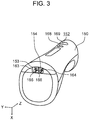
- FIG. 3 is a perspective view showing a care apparatus according to the exemplary embodiment from a bottom.
- FIG. 4 is a view schematically showing an inner structure of the care apparatus according to the exemplary embodiment from a side.
- Care apparatus 105 is an apparatus that cares for an inside of a month or hair of a person or an animal by power of a storage battery.
- an oral washer is exemplified as care apparatus 105.
- care apparatus 105 is a compact apparatus that can be held with one hand of a person, and includes nozzle 151 (see FIG. 4 ) and apparatus body 152 (see FIG. 4 ).
- Nozzle 151 is a member that includes a discharge port that discharges a liquid between teeth, and is detachably attached to an upper end of apparatus body 152.
- Nozzle 151 forms a passage through which a liquid such as water whose pressure has been increased by apparatus body 152 is discharged in a predetermined direction.
- the passage of the liquid formed by nozzle 151 has a venturi structure, and decreases the pressure to a saturated steam pressure by increasing a flow velocity of the liquid. Accordingly, a part of the liquid is changed into a gas, and thus bubbles are generated in the liquid.
- the passage changes the babbles into a liquid by gradually recovering the pressure of the liquid so that the pressure of the liquid is restored to be equal to or more than the saturated steam pressure. At this time, the bubbles burst and thus high shock waves are momentarily generated. These shock waves can be used for removal of a dirt inside the mouth, particularly a dirt between teeth.
- Apparatus body 152 is an apparatus that discharges a liquid through nozzle 151, and includes apparatus housing 150 having a substantially cylindrical shape when viewed as a whole that can be easily held with one hand of a person. Since apparatus housing 150 is caught in an edge of a palm of a hand that holds apparatus housing 150, a burden on an arm due to a weight of care apparatus 105 can be reduced.
- Apparatus body 152 includes third cover 153, fourth cover 154 (see FIG. 3 ), third terminal 163, and fourth terminal 164 at the bottom of apparatus housing 150.
- apparatus body 152 includes storage battery 156, power storage controller 157, driving source 158, pressure raising discharge mechanism 159, tank 160, and tube 161 inside. Note that third cover 153, fourth cover 154, third terminal 163, and fourth terminal 164 will be described later together with first cover 111, second cover 112, first terminal 121, and second terminal 122.
- Storage battery 156 is a secondary battery that can store power by being supplied with power and can supply the stored power to driving source 158 and the like.
- a type of storage battery 156 is not particularly limited.
- a lithium ion battery and the like can be exemplified.
- Power storage controller 157 is a circuit that monitors a power storage amount of storage battery 156 and can block a supply of power to storage battery 156 when storage battery 156 is fully charged. Note that power storage controller 157 does not have to be included in care apparatus 105.
- Driving source 158 is an apparatus that generates driving force for driving pressure raising discharge mechanism 159.
- Driving source 158 is not particularly limited. An electric motor and the like can be exemplified.
- Pressure raising discharge mechanism 159 is a mechanism that lifts a liquid in tank 160 through tube 161, increases the pressure of the lifted liquid to a predetermined pressure, and then discharges the liquid.
- Pressure raising discharge mechanism 159 is not particularly limited.
- a mechanism can be exemplified that lifts a liquid, increases a pressure, and discharges the liquid through using of a piston that is caused to reciprocate by driving source 158 and a combination of a plurality of valves.
- a front of apparatus body 152 is provided with power button 169 and adjustment button 168 for adjusting the pressure of the liquid discharged from nozzle 151.
- Power button 169, adjustment button 168 and the like are electrically connected to a controller that is not shown.
- the controller is, for example, a microcomputer and is incorporated in apparatus body 152.
- a user who holds apparatus body 152 with nozzle 151 attached disposes a tip end of nozzle 151 near an area between teeth and operates power button 169 so as to discharge the liquid to the area between the teeth and care for the inside of the mouth.
- FIG. 5 is a sectional view taken along line I-I in FIG. 1 showing a terminal portion of the care unit when the care apparatus is attached to the charging stand.
- FIG. 6 is a sectional view taken along line II-II in FIG. 1 showing the terminal portion of the care unit when the care apparatus is attached to the charging stand.
- charging stand 101 includes first terminal 121, second terminal 122, first cover 111, and second cover 112.
- Care apparatus 105 includes third terminal 163, fourth terminal 164, third cover 153, and fourth cover 154.
- First terminal 121 and second terminal 122 are connection terminals that are electrically connected to third terminal 163 and fourth terminal 164, respectively, and supply power transmitted through power supply cable 201 to care apparatus 105.
- the power supplied through power supply cable 201 is a direct-current voltage suitable to charge storage battery 156, and first terminal 121 and second terminal 122 each are electrically connected to power supply cable 201.
- First terminal 121 is electrically connected to third terminal 163 with a unidirectional biasing force only, and second terminal 122 is electrically connected to fourth terminal 164 with a unidirectional biasing force only.
- a generation source of the biasing force is not particularly limited.
- a biasing member such as a rubber or a spring that biases first terminal 121 and second terminal 122 separately or integrally may be included.
- first terminal 121 and second terminal 122 are formed of a material having an elastic force such as spring steel, and the elastic forces of first terminal 121 and second terminal 122 enable first terminal 121 and second terminal 122 to connect to third terminal 163 and fourth terminal 164, respectively.
- an axis of a biasing direction of first terminal 121 is parallel to an axis of a biasing direction of second terminal 122.
- the axis of the biasing direction of first terminal 121 and the axis of the biasing direction of second terminal 122 are parallel to an axis of a direction extending from an end of charging stand 101 where guide 113 is provided toward an end of an opposite side (X-axis in the drawing).
- the biasing direction of first terminal 121 extends from the end where guide 113 is provided toward the end of the opposite side (negative direction of the X-axis in the drawing).
- the biasing direction of second terminal 122 is a same direction as the biasing direction of first terminal 121.
- a shape of first terminal 121 and a shape of second terminal 122 are identical, and same parts can be used for first terminal 121 and second terminal 122.
- First cover 111 is a portion having a cylindrical shape that includes first opening 131, into which third terminal 163 is inserted, and stores first terminal 121.
- Second cover 112 is a portion having a cylindrical shape that includes second opening 132, into which fourth terminal 164 is inserted, and stores second terminal 122.
- first cover 111 and second cover 112 each are a portion that protrudes from placing surface 110 toward a side of care apparatus 105 that is held.
- First cover 111 and second cover 112 are disposed side by side in a direction orthogonal to the biasing direction of first terminal 121 and second terminal 122.
- An outer shape of first cover 111 and an outer shape of second cover 112 each are a quadrangular pyramid that tapers from placing surface 110 toward a protruding direction (positive direction of the Z-axis direction in the drawing). Vicinities of first cover 111 and second cover 112 on placing surfaces 110 are connected to each other.
- each of first opening 131 and second opening 132 provided on a top surface of first cover 111 and a top surface of second cover 112, respectively is not a perfect circle.
- Two adjacent sides of each of a bounding rectangle of first opening 131 and a bounding rectangle of second opening 132 are different in length.
- a bounding rectangle refers to a smallest rectangle that can surround a contour.
- the shape of each of first opening 131 and second opening 132 is an oval shape including an oblong shape and an elliptical shape.
- First opening 131 and second opening 132 are disposed so that longitudinal directions of first opening 131 and second opening 132 are parallel to the biasing directions of first terminal 121 and second terminal 122, respectively.
- first opening 131 and second opening 132 are set so that there is a gap between third terminal 163 and fourth terminal 164 that have been inserted. Note that in a case where the position in which care apparatus 105 is held with respect to charging stand 101 is displaced from the predetermined position, at least one of a pair of first opening 131 and third terminal 163, and a pair of second opening 132 and fourth terminal 164 may come into contact with each other.
- Third terminal 163 is a connection terminal that is detachably and electrically connected to first terminal 121.
- Fourth terminal 164 is a connection terminal that is detachably and electrically connected to second terminal 122.
- third terminal 163 and fourth terminal 164 are connected to storage battery 156 through power storage controller 157, and supply power relayed by charging stand 101 to storage battery 156.
- Third terminal 163 and fourth terminal 164 each are a rod-shaped member having rigidity that can maintain the shape against the biasing force of each of first terminal 121 and second terminal 122.
- third terminal 163 and fourth terminal 164 each are a round rod.
- Third cover 153 is a portion having a cylindrical shape that includes third opening 165, into which first cover 111 is inserted, and stores at least a part of third terminal 163.
- Fourth cover 154 is a portion having a cylindrical shape that includes fourth opening 166, into which second cover 112 is inserted, and stores at least a part of fourth terminal 164.
- third cover 153 and fourth cover 154 each are a portion recessed inward from the bottom of care apparatus 105.
- Third cover 153 and fourth cover 154 are disposed side by side in the direction orthogonal to the biasing directions of first terminal 121 and second terminal 122.
- An inner shape of third cover 153 and an inner shape of fourth cover 154 correspond to the outer shape of first cover 111 and the outer shape of second cover 112, respectively, and each are a quadrangular pyramid that tapers inward from the bottom (positive direction of the Z-axis direction in the drawing).
- Wall surfaces of third cover 153 and fourth cover 154 are partially shared, and a shared wall surface 118 separates third terminal 163 from fourth terminal 164.
- third terminal 163 and fourth terminal 164 are attached to ceiling surfaces of third cover 153 and fourth cover 154, respectively, in a protruded manner.
- the sizes of the outer shape of first cover 111, the outer shape of second cover 112, the inner shape of third cover 153, and the inner shape of fourth cover 154 are set so that, in a radial direction orthogonal to an insertion direction of first cover 111, an entire periphery of third cover 153 is not in contact with an entire periphery of first cover 111, and in a radial direction orthogonal to an insertion direction of second cover 112, an entire periphery of fourth cover 154 is not in contact with an entire periphery of second cover 112. That is, while care apparatus 105 is held in the predetermined position of charging stand 101, gap C exists between first cover 111 and third cover 153, and between second cover 112 and fourth cover 154 (see FIGS. 5 and 6 ).
- care apparatus 105 when care apparatus 105 is attached to or detached from charging stand 101, in particular, when care apparatus 105 is removed from charging stand 101, first cover 111 and third cover 153, and second cover 112 and fourth cover 154 do not rub against each other. Therefore, even if charging stand 101 is placed on a washstand or the like without being fixed, care apparatus 105 can be removed from charging stand 101 without holding down of charging stand 101 with a hand or the like. As a result, care apparatus 105 can be easily removed from charging stand 101 while being held by a hand, and care apparatus 105 can be easily used. In addition, after a use of care apparatus 105, care apparatus 105 can be easily attached to charging stand 101 to start charging of care apparatus 105.
- first terminal 121 and second terminal 122 are covered and protected by first cover 111 and second cover 112, respectively, for example, first terminal 121 and second terminal 122 can be prevented from being in contact with a liquid such as dripped water from care apparatus 105 to charging stand 101.
- gap C is provided between first cover 111 and third cover 153, and second cover 112 and fourth cover 154, both water repellence and easiness of attachment and detachment can be achieved.
- first cover 111 and second cover 112 provided on placing surface 110 of charging stand 101 serve as marks that show a position when care apparatus 105 is disposed on charging stand 101, and an engagement of recesses and projections contributes to prevention of displacement after disposition.
- charging stand 101 not only relays power, but may include a circuit such as a voltage lowering circuit and a direct current conversion circuit.
- first terminal 121 and second terminal 122 are provided in charging stand 101 and third terminal 163 and fourth terminal 164 are provided in care apparatus 105 has been described.
- first terminal 121 and fourth terminal 164 may be included in charging stand 101, and second terminal 122 and third terminal 163 may be included in care apparatus 105.
- first terminal 121 and third terminal 163 may be biased, and at least one of second terminal 122 and fourth terminal 164 may be biased.
- each of first cover 111, second cover 112, third cover 153, and fourth cover 154 is not limited to a quadrangular pyramid, and an arbitrary shape such as a truncated cone can be applied.
- first cover 111 and the ceiling surface of third cover 153, and the top surface of second cover 112 and the ceiling surface of fourth cover 154 may come into contact with each other.
- the present disclosure can be applied to a compact care apparatus including a storage battery.
Landscapes
- Health & Medical Sciences (AREA)
- Dentistry (AREA)
- Epidemiology (AREA)
- Life Sciences & Earth Sciences (AREA)
- Animal Behavior & Ethology (AREA)
- General Health & Medical Sciences (AREA)
- Public Health (AREA)
- Veterinary Medicine (AREA)
- Charge And Discharge Circuits For Batteries Or The Like (AREA)
- Engineering & Computer Science (AREA)
- Power Engineering (AREA)
Claims (6)
- Pflege-Einheit (100), die eine Pflegevorrichtung (105) und eine Ladestation (101) enthält, wobei die Pflegevorrichtung (105) einen Akku (156) enthält, die Ladestation (101) elektrisch mit der Pflegevorrichtung (105) verbunden ist und die Pflege-Einheit (100) umfasst:einen ersten Anschluss (121);einen zweiten Anschluss (122);einen dritten Anschluss (163), der lösbar mit dem ersten Anschluss (121) verbunden ist;einen vierten Anschluss (164), der lösbar mit dem zweiten Anschluss (122) verbunden ist;eine erste Abdeckung (111), die eine zylindrische Form hat, wobei die erste Abdeckung (111) eine erste Öffnung (131) enthält, die Einführung des dritten Anschlusses (163) ermöglicht und wenigstens einen Teil des ersten Anschlusses (121) aufnimmt;eine zweite Abdeckung (112), die eine zylindrische Form hat, wobei die zweite Abdeckung (112) eine zweite Öffnung (132) enthält, die Einführung des vierten Anschlusses (164) ermöglicht und wenigstens einen Teil des zweiten Anschlusses (122) aufnimmt, gekennzeichnet durcheine dritte Abdeckung (153), die eine zylindrische Form hat, wobei die dritte Abdeckung (153) eine dritte Öffnung (165) enthält, die Einführung der ersten Abdeckung (111) ermöglicht und wenigstens einen Teil des dritten Anschlusses (163) aufnimmt; sowieeine vierte Abdeckung (154), die eine zylindrische Form hat, wobei die vierte Abdeckung (154) eine vierte Öffnung (166) enthält, die Einführung der zweiten Abdeckung (112) ermöglicht und wenigstens einen Teil des vierten Anschlusses (164) aufnimmt,wobei, wenn die Pflegevorrichtung (105) an einer vorgegebenen Position der Ladestation gehalten wird, die dritte Abdeckung (153) nicht in Kontakt mit der ersten Abdeckung (111) in einer radialen Richtung im rechten Winkel zu einer Einführungsrichtung der ersten Abdeckung (111) ist, und die vierte Abdeckung (154) nicht in Kontakt mit der zweiten Abdeckung (112) in einer radialen Richtung im rechten Winkel zu einer Einführungsrichtung der zweiten Abdeckung (112) ist.
- Pflege-Einheit (100) nach Anspruch 1, wobei
der erste Anschluss (121) mit dem dritten Anschluss (163) nur mit einer unidirektionalen Vorspannkraft verbunden ist, und
der zweite Anschluss (122) mit dem vierten Anschluss (164) nur mit einer unidirektionalen Vorspannkraft verbunden ist. - Pflege-Einheit (100) nach Anspruch 2, wobei eine Achse einer Vorspannrichtung des ersten Anschlusses (121) parallel zu einer Achse einer Vorspannrichtung des zweiten Anschlusses (122) ist.
- Pflege-Einheit (100) nach einem der Ansprüche 1 bis 3, wobei zwei benachbarte Seiten eines begrenzenden Rechtecks der ersten Öffnung (131) und eines begrenzenden Rechtecks der zweiten Öffnung (132) jeweils unterschiedlich lang sind.
- Pflege-Einheit (100) nach einem der Ansprüche 1 bis 4, wobei die Ladestation (101) eine Führung (113) enthält, die die Pflegevorrichtung (105) in einer vorgegebenen Position hält.
- Pflege-Einheit (100) nach Anspruch 5, wobei die Führung (113) einen Abschnitt (114) zum Regulieren von Drehung umfasst, der Verschiebung der Pflegevorrichtung (105) in Bezug auf die Ladestation (101) in einer Drehrichtung reguliert.
Applications Claiming Priority (1)
| Application Number | Priority Date | Filing Date | Title |
|---|---|---|---|
| JP2019014582A JP7340786B2 (ja) | 2019-01-30 | 2019-01-30 | ケアユニット |
Publications (2)
| Publication Number | Publication Date |
|---|---|
| EP3689293A1 EP3689293A1 (de) | 2020-08-05 |
| EP3689293B1 true EP3689293B1 (de) | 2021-07-07 |
Family
ID=69174401
Family Applications (1)
| Application Number | Title | Priority Date | Filing Date |
|---|---|---|---|
| EP20152211.7A Active EP3689293B1 (de) | 2019-01-30 | 2020-01-16 | Pflegeeinheit |
Country Status (4)
| Country | Link |
|---|---|
| US (1) | US10923870B2 (de) |
| EP (1) | EP3689293B1 (de) |
| JP (1) | JP7340786B2 (de) |
| CN (1) | CN111494045B (de) |
Families Citing this family (5)
| Publication number | Priority date | Publication date | Assignee | Title |
|---|---|---|---|---|
| USD948033S1 (en) * | 2020-02-27 | 2022-04-05 | Shenzhen Fortunecome Technology Co., Ltd. | Oral irrigator |
| USD948032S1 (en) * | 2020-06-15 | 2022-04-05 | Shenzhen Fortunecome Technology Co., Ltd. | Oral irrigator |
| USD959649S1 (en) * | 2020-10-14 | 2022-08-02 | Shenzhen Yuxinyuan Electronic Technology Co., Ltd. | Water flosser |
| USD998142S1 (en) * | 2022-08-31 | 2023-09-05 | Hunan Accurate Bio-Medical Technology Co., Ltd | Oral or nasal irrigator |
| USD1061878S1 (en) * | 2023-06-23 | 2025-02-11 | Water Pik, Inc. | Oral irrigator |
Family Cites Families (50)
| Publication number | Priority date | Publication date | Assignee | Title |
|---|---|---|---|---|
| US2101345A (en) * | 1936-03-20 | 1937-12-07 | Riley Lee Hunter | Electrical connecter plug |
| US3359635A (en) * | 1965-01-05 | 1967-12-26 | Sunbeam Corp | Electrically operated dry shaver |
| DE2211262A1 (de) * | 1972-03-09 | 1973-09-13 | Moser Gmbh Kuno | Wiederaufladbare elektrohaarschneidemaschine |
| JPS5296388A (en) * | 1976-02-10 | 1977-08-12 | Matsushita Electric Works Ltd | Power supply coupling device for rechargeable appliance |
| JPS57156636A (en) * | 1981-03-23 | 1982-09-28 | Matsushita Electric Works Ltd | Charger |
| JPS60213229A (ja) | 1984-04-05 | 1985-10-25 | 松下電工株式会社 | 充電装置 |
| JPS6161764U (de) * | 1984-09-26 | 1986-04-25 | ||
| US4622507A (en) * | 1985-02-01 | 1986-11-11 | David Persen | Integrated battery and recharger |
| DE3516774A1 (de) * | 1985-05-09 | 1986-11-13 | Wilhelm Sedlbauer GmbH Fabrik für Feinmechanik und Elektronik, 8000 München | Bearbeitungsgeraet zur oertlichen bestrahlung mit sichtbarem oder unsichtbarem licht |
| JPS62123666A (ja) * | 1985-11-25 | 1987-06-04 | Matsushita Electric Works Ltd | 充電式電気機器 |
| JPH039261Y2 (de) * | 1985-12-18 | 1991-03-07 | ||
| JPH05315014A (ja) * | 1992-05-11 | 1993-11-26 | Ricoh Elemex Corp | 充電式電気機器 |
| JPH0687812B2 (ja) * | 1992-11-20 | 1994-11-09 | 松下電工株式会社 | 電動歯ブラシ |
| JP2849300B2 (ja) * | 1993-03-15 | 1999-01-20 | ローム株式会社 | コードレス電話機 |
| EP0634151B1 (de) * | 1993-03-24 | 1999-07-28 | Koninklijke Philips Electronics N.V. | Elektrische Zahnbürste |
| JPH0833656A (ja) * | 1994-07-26 | 1996-02-06 | Matsushita Electric Works Ltd | 口腔洗浄器 |
| US5699575A (en) * | 1995-10-23 | 1997-12-23 | Peifer; Melvin W. | Flexible rotary toothbrush |
| JPH1028335A (ja) * | 1996-07-09 | 1998-01-27 | Saitama Nippon Denki Kk | 充電器構造 |
| US6845537B2 (en) * | 2001-02-06 | 2005-01-25 | Man-Kwan Wong | Automatic power-driven toothbrushes |
| JP3486564B2 (ja) * | 1998-07-28 | 2004-01-13 | 株式会社トップランド | 携帯電子機器用補助電源体 |
| JP3789714B2 (ja) * | 2000-02-29 | 2006-06-28 | 三洋電機株式会社 | 電気器具の電源プラグ連結構造 |
| EP1404245A4 (de) * | 2001-07-12 | 2006-04-05 | Water Pik Inc | Zweimotorige orale hygienevorrichtung |
| JP3937396B2 (ja) * | 2002-06-14 | 2007-06-27 | 九州日立マクセル株式会社 | 充電器 |
| JP5407175B2 (ja) | 2008-05-09 | 2014-02-05 | オムロンヘルスケア株式会社 | 電動歯ブラシシステム |
| EP2229916B1 (de) * | 2009-03-19 | 2016-06-01 | Braun GmbH | Verfahren zum Bestimmen eines Verwendungsmusters einer elektrischen Zahnbürste und elektrische Zahnbürste |
| US20120147595A1 (en) * | 2010-12-08 | 2012-06-14 | Ching-Hsiang Wang | Flashlight Charging Composition Capable of Magnetic Positioning |
| JP2012226994A (ja) * | 2011-04-20 | 2012-11-15 | Kyowa Densen Kk | コネクタ構造および雌コンタクト |
| US8863416B2 (en) * | 2011-10-28 | 2014-10-21 | Polygroup Macau Limited (Bvi) | Powered tree construction |
| FR2991161B1 (fr) * | 2012-06-05 | 2014-07-11 | Itena Clinical | Piece a main pour traitement endodontique |
| CN104994766B (zh) * | 2013-03-15 | 2017-10-03 | 洁碧有限公司 | 机械驱动式声波牙刷和水牙线 |
| US9437960B2 (en) * | 2013-12-19 | 2016-09-06 | Youhua Technology (Shenzhen) Co., Ltd | Dustproof cover for charging port of electronic device and charging base corresponding to dustproof cover |
| US9907634B2 (en) * | 2014-04-16 | 2018-03-06 | Koninklijke Philips N.V. | Multifunction bobbin design |
| JP2015208472A (ja) * | 2014-04-25 | 2015-11-24 | オムロンヘルスケア株式会社 | 充電式バッテリを備えた電動歯ブラシ |
| US9839491B2 (en) * | 2014-09-02 | 2017-12-12 | Cao Group, Inc. | Dental handpieces |
| US9891680B2 (en) * | 2014-11-19 | 2018-02-13 | Dell Products L.P. | Information handling system multi-purpose connector guide pin structure |
| JP6499869B2 (ja) * | 2015-01-21 | 2019-04-10 | 矢崎総業株式会社 | コネクタおよびコネクタ構造 |
| US10512528B2 (en) * | 2015-04-06 | 2019-12-24 | Panasonic Intellectual Property Management Co., Ltd. | Non-contact power supply device |
| CN107431371B (zh) * | 2015-04-06 | 2021-02-09 | 松下知识产权经营株式会社 | 电气设备单元 |
| CN106794058B (zh) * | 2015-05-27 | 2018-11-16 | 皇家飞利浦有限公司 | 用于具有壳体的电动牙刷的壳体互锁件以及电动牙刷 |
| US10321976B2 (en) * | 2016-06-02 | 2019-06-18 | Hari Mark Reyes | Composite extraction pen |
| CN106999268B (zh) * | 2016-06-03 | 2018-07-10 | 爱模系统有限公司 | 牙刷用振动器 |
| CN106236305B (zh) * | 2016-09-08 | 2018-05-25 | 吴晓旺 | 一种电动牙刷 |
| CA3128828C (en) * | 2016-12-15 | 2023-09-19 | Water Pik, Inc. | Brushing device with illumination features |
| US10734746B2 (en) * | 2017-07-28 | 2020-08-04 | Casio Computer Co., Ltd. | Terminal structure, portable terminal and manufacturing method of terminal section |
| US10624725B2 (en) * | 2017-08-23 | 2020-04-21 | Brian King | Oral rinsing apparatus |
| JP6990557B2 (ja) * | 2017-10-11 | 2022-01-12 | 株式会社オーディオテクニカ | マイクロホン用充電器 |
| TWM564272U (zh) * | 2017-12-20 | 2018-07-21 | 麗臺科技股份有限公司 | 充電插頭與充電結構 |
| TWM568526U (zh) * | 2018-05-31 | 2018-10-11 | 正崴精密工業股份有限公司 | 電動車充電連接器總成 |
| KR20210124009A (ko) * | 2019-02-11 | 2021-10-14 | 테라건, 인크. | 충전 스탠드 |
| CN110225657A (zh) * | 2019-06-06 | 2019-09-10 | 英业达科技有限公司 | 电路板及其电池座 |
-
2019
- 2019-01-30 JP JP2019014582A patent/JP7340786B2/ja active Active
-
2020
- 2020-01-06 CN CN202010009862.6A patent/CN111494045B/zh active Active
- 2020-01-08 US US16/737,736 patent/US10923870B2/en active Active
- 2020-01-16 EP EP20152211.7A patent/EP3689293B1/de active Active
Also Published As
| Publication number | Publication date |
|---|---|
| EP3689293A1 (de) | 2020-08-05 |
| CN111494045B (zh) | 2022-09-16 |
| US10923870B2 (en) | 2021-02-16 |
| JP2020124043A (ja) | 2020-08-13 |
| JP7340786B2 (ja) | 2023-09-08 |
| CN111494045A (zh) | 2020-08-07 |
| US20200244023A1 (en) | 2020-07-30 |
Similar Documents
| Publication | Publication Date | Title |
|---|---|---|
| EP3689293B1 (de) | Pflegeeinheit | |
| US11424631B2 (en) | Charging stand for care apparatus that prevents corrosion of terminals | |
| EP2180983B1 (de) | Körperpflegevorrichtung | |
| US7877880B2 (en) | Hand held personal care appliance | |
| US8869809B2 (en) | Shaving system | |
| ES2907725T3 (es) | Dispositivo de suavizado dérmico portátil | |
| EP3689292B1 (de) | Mundhöhlenwaschvorrichtung | |
| US10966807B1 (en) | Electric toothbrushes | |
| JP2009039841A (ja) | 充電式電動工具の電気接続装置 | |
| CN221436534U (zh) | 用于实验动物的剃毛吸毛组合装置 | |
| JP2005347900A (ja) | 携帯電話用の充電装置 | |
| EP2979316B1 (de) | Verzögerungsmechanismus | |
| CN215229995U (zh) | 一种颈部按摩仪 | |
| JP6662620B2 (ja) | 電動歯ブラシ | |
| JP4100047B2 (ja) | 体毛処理器具の処理剤供給装置 | |
| JP2024010285A (ja) | 振動付与装置 | |
| KR200232200Y1 (ko) | 슬림형 전기 면도기 | |
| US20070103111A1 (en) | Power Insert | |
| ZA200810714B (en) | An electrical toothbrush to shaver adapter | |
| JPH0595328U (ja) | 電動歯ブラシ |
Legal Events
| Date | Code | Title | Description |
|---|---|---|---|
| PUAI | Public reference made under article 153(3) epc to a published international application that has entered the european phase |
Free format text: ORIGINAL CODE: 0009012 |
|
| STAA | Information on the status of an ep patent application or granted ep patent |
Free format text: STATUS: REQUEST FOR EXAMINATION WAS MADE |
|
| 17P | Request for examination filed |
Effective date: 20200116 |
|
| AK | Designated contracting states |
Kind code of ref document: A1 Designated state(s): AL AT BE BG CH CY CZ DE DK EE ES FI FR GB GR HR HU IE IS IT LI LT LU LV MC MK MT NL NO PL PT RO RS SE SI SK SM TR |
|
| AX | Request for extension of the european patent |
Extension state: BA ME |
|
| GRAP | Despatch of communication of intention to grant a patent |
Free format text: ORIGINAL CODE: EPIDOSNIGR1 |
|
| STAA | Information on the status of an ep patent application or granted ep patent |
Free format text: STATUS: GRANT OF PATENT IS INTENDED |
|
| INTG | Intention to grant announced |
Effective date: 20210406 |
|
| GRAS | Grant fee paid |
Free format text: ORIGINAL CODE: EPIDOSNIGR3 |
|
| GRAA | (expected) grant |
Free format text: ORIGINAL CODE: 0009210 |
|
| STAA | Information on the status of an ep patent application or granted ep patent |
Free format text: STATUS: THE PATENT HAS BEEN GRANTED |
|
| AK | Designated contracting states |
Kind code of ref document: B1 Designated state(s): AL AT BE BG CH CY CZ DE DK EE ES FI FR GB GR HR HU IE IS IT LI LT LU LV MC MK MT NL NO PL PT RO RS SE SI SK SM TR |
|
| REG | Reference to a national code |
Ref country code: GB Ref legal event code: FG4D |
|
| REG | Reference to a national code |
Ref country code: AT Ref legal event code: REF Ref document number: 1407832 Country of ref document: AT Kind code of ref document: T Effective date: 20210715 |
|
| REG | Reference to a national code |
Ref country code: DE Ref legal event code: R096 Ref document number: 602020000210 Country of ref document: DE |
|
| REG | Reference to a national code |
Ref country code: IE Ref legal event code: FG4D |
|
| REG | Reference to a national code |
Ref country code: LT Ref legal event code: MG9D |
|
| REG | Reference to a national code |
Ref country code: NL Ref legal event code: MP Effective date: 20210707 |
|
| REG | Reference to a national code |
Ref country code: AT Ref legal event code: MK05 Ref document number: 1407832 Country of ref document: AT Kind code of ref document: T Effective date: 20210707 |
|
| PG25 | Lapsed in a contracting state [announced via postgrant information from national office to epo] |
Ref country code: SE Free format text: LAPSE BECAUSE OF FAILURE TO SUBMIT A TRANSLATION OF THE DESCRIPTION OR TO PAY THE FEE WITHIN THE PRESCRIBED TIME-LIMIT Effective date: 20210707 Ref country code: RS Free format text: LAPSE BECAUSE OF FAILURE TO SUBMIT A TRANSLATION OF THE DESCRIPTION OR TO PAY THE FEE WITHIN THE PRESCRIBED TIME-LIMIT Effective date: 20210707 Ref country code: ES Free format text: LAPSE BECAUSE OF FAILURE TO SUBMIT A TRANSLATION OF THE DESCRIPTION OR TO PAY THE FEE WITHIN THE PRESCRIBED TIME-LIMIT Effective date: 20210707 Ref country code: FI Free format text: LAPSE BECAUSE OF FAILURE TO SUBMIT A TRANSLATION OF THE DESCRIPTION OR TO PAY THE FEE WITHIN THE PRESCRIBED TIME-LIMIT Effective date: 20210707 Ref country code: HR Free format text: LAPSE BECAUSE OF FAILURE TO SUBMIT A TRANSLATION OF THE DESCRIPTION OR TO PAY THE FEE WITHIN THE PRESCRIBED TIME-LIMIT Effective date: 20210707 Ref country code: NL Free format text: LAPSE BECAUSE OF FAILURE TO SUBMIT A TRANSLATION OF THE DESCRIPTION OR TO PAY THE FEE WITHIN THE PRESCRIBED TIME-LIMIT Effective date: 20210707 Ref country code: PT Free format text: LAPSE BECAUSE OF FAILURE TO SUBMIT A TRANSLATION OF THE DESCRIPTION OR TO PAY THE FEE WITHIN THE PRESCRIBED TIME-LIMIT Effective date: 20211108 Ref country code: NO Free format text: LAPSE BECAUSE OF FAILURE TO SUBMIT A TRANSLATION OF THE DESCRIPTION OR TO PAY THE FEE WITHIN THE PRESCRIBED TIME-LIMIT Effective date: 20211007 Ref country code: BG Free format text: LAPSE BECAUSE OF FAILURE TO SUBMIT A TRANSLATION OF THE DESCRIPTION OR TO PAY THE FEE WITHIN THE PRESCRIBED TIME-LIMIT Effective date: 20211007 Ref country code: AT Free format text: LAPSE BECAUSE OF FAILURE TO SUBMIT A TRANSLATION OF THE DESCRIPTION OR TO PAY THE FEE WITHIN THE PRESCRIBED TIME-LIMIT Effective date: 20210707 Ref country code: LT Free format text: LAPSE BECAUSE OF FAILURE TO SUBMIT A TRANSLATION OF THE DESCRIPTION OR TO PAY THE FEE WITHIN THE PRESCRIBED TIME-LIMIT Effective date: 20210707 |
|
| PG25 | Lapsed in a contracting state [announced via postgrant information from national office to epo] |
Ref country code: PL Free format text: LAPSE BECAUSE OF FAILURE TO SUBMIT A TRANSLATION OF THE DESCRIPTION OR TO PAY THE FEE WITHIN THE PRESCRIBED TIME-LIMIT Effective date: 20210707 Ref country code: LV Free format text: LAPSE BECAUSE OF FAILURE TO SUBMIT A TRANSLATION OF THE DESCRIPTION OR TO PAY THE FEE WITHIN THE PRESCRIBED TIME-LIMIT Effective date: 20210707 Ref country code: GR Free format text: LAPSE BECAUSE OF FAILURE TO SUBMIT A TRANSLATION OF THE DESCRIPTION OR TO PAY THE FEE WITHIN THE PRESCRIBED TIME-LIMIT Effective date: 20211008 |
|
| REG | Reference to a national code |
Ref country code: DE Ref legal event code: R097 Ref document number: 602020000210 Country of ref document: DE |
|
| PG25 | Lapsed in a contracting state [announced via postgrant information from national office to epo] |
Ref country code: DK Free format text: LAPSE BECAUSE OF FAILURE TO SUBMIT A TRANSLATION OF THE DESCRIPTION OR TO PAY THE FEE WITHIN THE PRESCRIBED TIME-LIMIT Effective date: 20210707 |
|
| PLBE | No opposition filed within time limit |
Free format text: ORIGINAL CODE: 0009261 |
|
| STAA | Information on the status of an ep patent application or granted ep patent |
Free format text: STATUS: NO OPPOSITION FILED WITHIN TIME LIMIT |
|
| PG25 | Lapsed in a contracting state [announced via postgrant information from national office to epo] |
Ref country code: SM Free format text: LAPSE BECAUSE OF FAILURE TO SUBMIT A TRANSLATION OF THE DESCRIPTION OR TO PAY THE FEE WITHIN THE PRESCRIBED TIME-LIMIT Effective date: 20210707 Ref country code: SK Free format text: LAPSE BECAUSE OF FAILURE TO SUBMIT A TRANSLATION OF THE DESCRIPTION OR TO PAY THE FEE WITHIN THE PRESCRIBED TIME-LIMIT Effective date: 20210707 Ref country code: RO Free format text: LAPSE BECAUSE OF FAILURE TO SUBMIT A TRANSLATION OF THE DESCRIPTION OR TO PAY THE FEE WITHIN THE PRESCRIBED TIME-LIMIT Effective date: 20210707 Ref country code: EE Free format text: LAPSE BECAUSE OF FAILURE TO SUBMIT A TRANSLATION OF THE DESCRIPTION OR TO PAY THE FEE WITHIN THE PRESCRIBED TIME-LIMIT Effective date: 20210707 Ref country code: CZ Free format text: LAPSE BECAUSE OF FAILURE TO SUBMIT A TRANSLATION OF THE DESCRIPTION OR TO PAY THE FEE WITHIN THE PRESCRIBED TIME-LIMIT Effective date: 20210707 Ref country code: AL Free format text: LAPSE BECAUSE OF FAILURE TO SUBMIT A TRANSLATION OF THE DESCRIPTION OR TO PAY THE FEE WITHIN THE PRESCRIBED TIME-LIMIT Effective date: 20210707 |
|
| 26N | No opposition filed |
Effective date: 20220408 |
|
| PG25 | Lapsed in a contracting state [announced via postgrant information from national office to epo] |
Ref country code: IT Free format text: LAPSE BECAUSE OF FAILURE TO SUBMIT A TRANSLATION OF THE DESCRIPTION OR TO PAY THE FEE WITHIN THE PRESCRIBED TIME-LIMIT Effective date: 20210707 |
|
| PG25 | Lapsed in a contracting state [announced via postgrant information from national office to epo] |
Ref country code: MC Free format text: LAPSE BECAUSE OF FAILURE TO SUBMIT A TRANSLATION OF THE DESCRIPTION OR TO PAY THE FEE WITHIN THE PRESCRIBED TIME-LIMIT Effective date: 20210707 |
|
| REG | Reference to a national code |
Ref country code: BE Ref legal event code: MM Effective date: 20220131 |
|
| PG25 | Lapsed in a contracting state [announced via postgrant information from national office to epo] |
Ref country code: LU Free format text: LAPSE BECAUSE OF NON-PAYMENT OF DUE FEES Effective date: 20220116 |
|
| PG25 | Lapsed in a contracting state [announced via postgrant information from national office to epo] |
Ref country code: FR Free format text: LAPSE BECAUSE OF NON-PAYMENT OF DUE FEES Effective date: 20220131 Ref country code: BE Free format text: LAPSE BECAUSE OF NON-PAYMENT OF DUE FEES Effective date: 20220131 |
|
| PG25 | Lapsed in a contracting state [announced via postgrant information from national office to epo] |
Ref country code: IE Free format text: LAPSE BECAUSE OF NON-PAYMENT OF DUE FEES Effective date: 20220116 |
|
| REG | Reference to a national code |
Ref country code: CH Ref legal event code: PL |
|
| PG25 | Lapsed in a contracting state [announced via postgrant information from national office to epo] |
Ref country code: LI Free format text: LAPSE BECAUSE OF NON-PAYMENT OF DUE FEES Effective date: 20230131 Ref country code: CH Free format text: LAPSE BECAUSE OF NON-PAYMENT OF DUE FEES Effective date: 20230131 |
|
| PG25 | Lapsed in a contracting state [announced via postgrant information from national office to epo] |
Ref country code: MK Free format text: LAPSE BECAUSE OF FAILURE TO SUBMIT A TRANSLATION OF THE DESCRIPTION OR TO PAY THE FEE WITHIN THE PRESCRIBED TIME-LIMIT Effective date: 20210707 Ref country code: CY Free format text: LAPSE BECAUSE OF FAILURE TO SUBMIT A TRANSLATION OF THE DESCRIPTION OR TO PAY THE FEE WITHIN THE PRESCRIBED TIME-LIMIT Effective date: 20210707 |
|
| PG25 | Lapsed in a contracting state [announced via postgrant information from national office to epo] |
Ref country code: HU Free format text: LAPSE BECAUSE OF FAILURE TO SUBMIT A TRANSLATION OF THE DESCRIPTION OR TO PAY THE FEE WITHIN THE PRESCRIBED TIME-LIMIT; INVALID AB INITIO Effective date: 20200116 |
|
| GBPC | Gb: european patent ceased through non-payment of renewal fee |
Effective date: 20240116 |
|
| PG25 | Lapsed in a contracting state [announced via postgrant information from national office to epo] |
Ref country code: MT Free format text: LAPSE BECAUSE OF FAILURE TO SUBMIT A TRANSLATION OF THE DESCRIPTION OR TO PAY THE FEE WITHIN THE PRESCRIBED TIME-LIMIT Effective date: 20210707 |
|
| PG25 | Lapsed in a contracting state [announced via postgrant information from national office to epo] |
Ref country code: GB Free format text: LAPSE BECAUSE OF NON-PAYMENT OF DUE FEES Effective date: 20240116 |
|
| PG25 | Lapsed in a contracting state [announced via postgrant information from national office to epo] |
Ref country code: GB Free format text: LAPSE BECAUSE OF NON-PAYMENT OF DUE FEES Effective date: 20240116 |
|
| PGFP | Annual fee paid to national office [announced via postgrant information from national office to epo] |
Ref country code: DE Payment date: 20250121 Year of fee payment: 6 |
|
| PG25 | Lapsed in a contracting state [announced via postgrant information from national office to epo] |
Ref country code: TR Free format text: LAPSE BECAUSE OF FAILURE TO SUBMIT A TRANSLATION OF THE DESCRIPTION OR TO PAY THE FEE WITHIN THE PRESCRIBED TIME-LIMIT Effective date: 20210707 |