EP3684696B1 - Vorrichtung zum herstellen und befüllen von behältererzeugnissen - Google Patents
Vorrichtung zum herstellen und befüllen von behältererzeugnissen Download PDFInfo
- Publication number
- EP3684696B1 EP3684696B1 EP18768830.4A EP18768830A EP3684696B1 EP 3684696 B1 EP3684696 B1 EP 3684696B1 EP 18768830 A EP18768830 A EP 18768830A EP 3684696 B1 EP3684696 B1 EP 3684696B1
- Authority
- EP
- European Patent Office
- Prior art keywords
- process gas
- duct
- exhaust gas
- filling
- extrusion head
- Prior art date
- Legal status (The legal status is an assumption and is not a legal conclusion. Google has not performed a legal analysis and makes no representation as to the accuracy of the status listed.)
- Active
Links
Images



Classifications
-
- B—PERFORMING OPERATIONS; TRANSPORTING
- B65—CONVEYING; PACKING; STORING; HANDLING THIN OR FILAMENTARY MATERIAL
- B65B—MACHINES, APPARATUS OR DEVICES FOR, OR METHODS OF, PACKAGING ARTICLES OR MATERIALS; UNPACKING
- B65B3/00—Packaging plastic material, semiliquids, liquids or mixed solids and liquids, in individual containers or receptacles, e.g. bags, sacks, boxes, cartons, cans, or jars
- B65B3/02—Machines characterised by the incorporation of means for making the containers or receptacles
- B65B3/022—Making containers by moulding of a thermoplastic material
-
- B—PERFORMING OPERATIONS; TRANSPORTING
- B65—CONVEYING; PACKING; STORING; HANDLING THIN OR FILAMENTARY MATERIAL
- B65B—MACHINES, APPARATUS OR DEVICES FOR, OR METHODS OF, PACKAGING ARTICLES OR MATERIALS; UNPACKING
- B65B3/00—Packaging plastic material, semiliquids, liquids or mixed solids and liquids, in individual containers or receptacles, e.g. bags, sacks, boxes, cartons, cans, or jars
- B65B3/003—Filling medical containers such as ampoules, vials, syringes or the like
-
- B—PERFORMING OPERATIONS; TRANSPORTING
- B29—WORKING OF PLASTICS; WORKING OF SUBSTANCES IN A PLASTIC STATE IN GENERAL
- B29C—SHAPING OR JOINING OF PLASTICS; SHAPING OF MATERIAL IN A PLASTIC STATE, NOT OTHERWISE PROVIDED FOR; AFTER-TREATMENT OF THE SHAPED PRODUCTS, e.g. REPAIRING
- B29C48/00—Extrusion moulding, i.e. expressing the moulding material through a die or nozzle which imparts the desired form; Apparatus therefor
- B29C48/25—Component parts, details or accessories; Auxiliary operations
- B29C48/36—Means for plasticising or homogenising the moulding material or forcing it through the nozzle or die
- B29C48/50—Details of extruders
- B29C48/76—Venting, drying means; Degassing means
- B29C48/765—Venting, drying means; Degassing means in the extruder apparatus
-
- B—PERFORMING OPERATIONS; TRANSPORTING
- B29—WORKING OF PLASTICS; WORKING OF SUBSTANCES IN A PLASTIC STATE IN GENERAL
- B29C—SHAPING OR JOINING OF PLASTICS; SHAPING OF MATERIAL IN A PLASTIC STATE, NOT OTHERWISE PROVIDED FOR; AFTER-TREATMENT OF THE SHAPED PRODUCTS, e.g. REPAIRING
- B29C48/00—Extrusion moulding, i.e. expressing the moulding material through a die or nozzle which imparts the desired form; Apparatus therefor
- B29C48/001—Combinations of extrusion moulding with other shaping operations
- B29C48/0017—Combinations of extrusion moulding with other shaping operations combined with blow-moulding or thermoforming
-
- B—PERFORMING OPERATIONS; TRANSPORTING
- B29—WORKING OF PLASTICS; WORKING OF SUBSTANCES IN A PLASTIC STATE IN GENERAL
- B29C—SHAPING OR JOINING OF PLASTICS; SHAPING OF MATERIAL IN A PLASTIC STATE, NOT OTHERWISE PROVIDED FOR; AFTER-TREATMENT OF THE SHAPED PRODUCTS, e.g. REPAIRING
- B29C48/00—Extrusion moulding, i.e. expressing the moulding material through a die or nozzle which imparts the desired form; Apparatus therefor
- B29C48/03—Extrusion moulding, i.e. expressing the moulding material through a die or nozzle which imparts the desired form; Apparatus therefor characterised by the shape of the extruded material at extrusion
- B29C48/07—Flat, e.g. panels
- B29C48/08—Flat, e.g. panels flexible, e.g. films
-
- B—PERFORMING OPERATIONS; TRANSPORTING
- B29—WORKING OF PLASTICS; WORKING OF SUBSTANCES IN A PLASTIC STATE IN GENERAL
- B29C—SHAPING OR JOINING OF PLASTICS; SHAPING OF MATERIAL IN A PLASTIC STATE, NOT OTHERWISE PROVIDED FOR; AFTER-TREATMENT OF THE SHAPED PRODUCTS, e.g. REPAIRING
- B29C48/00—Extrusion moulding, i.e. expressing the moulding material through a die or nozzle which imparts the desired form; Apparatus therefor
- B29C48/25—Component parts, details or accessories; Auxiliary operations
- B29C48/30—Extrusion nozzles or dies
- B29C48/305—Extrusion nozzles or dies having a wide opening, e.g. for forming sheets
-
- B—PERFORMING OPERATIONS; TRANSPORTING
- B29—WORKING OF PLASTICS; WORKING OF SUBSTANCES IN A PLASTIC STATE IN GENERAL
- B29C—SHAPING OR JOINING OF PLASTICS; SHAPING OF MATERIAL IN A PLASTIC STATE, NOT OTHERWISE PROVIDED FOR; AFTER-TREATMENT OF THE SHAPED PRODUCTS, e.g. REPAIRING
- B29C49/00—Blow-moulding, i.e. blowing a preform or parison to a desired shape within a mould; Apparatus therefor
- B29C49/02—Combined blow-moulding and manufacture of the preform or the parison
- B29C49/04—Extrusion blow-moulding
-
- B—PERFORMING OPERATIONS; TRANSPORTING
- B29—WORKING OF PLASTICS; WORKING OF SUBSTANCES IN A PLASTIC STATE IN GENERAL
- B29C—SHAPING OR JOINING OF PLASTICS; SHAPING OF MATERIAL IN A PLASTIC STATE, NOT OTHERWISE PROVIDED FOR; AFTER-TREATMENT OF THE SHAPED PRODUCTS, e.g. REPAIRING
- B29C49/00—Blow-moulding, i.e. blowing a preform or parison to a desired shape within a mould; Apparatus therefor
- B29C49/28—Blow-moulding apparatus
- B29C49/30—Blow-moulding apparatus having movable moulds or mould parts
- B29C49/38—Blow-moulding apparatus having movable moulds or mould parts mounted on movable endless supports
-
- B—PERFORMING OPERATIONS; TRANSPORTING
- B29—WORKING OF PLASTICS; WORKING OF SUBSTANCES IN A PLASTIC STATE IN GENERAL
- B29C—SHAPING OR JOINING OF PLASTICS; SHAPING OF MATERIAL IN A PLASTIC STATE, NOT OTHERWISE PROVIDED FOR; AFTER-TREATMENT OF THE SHAPED PRODUCTS, e.g. REPAIRING
- B29C49/00—Blow-moulding, i.e. blowing a preform or parison to a desired shape within a mould; Apparatus therefor
- B29C49/42—Component parts, details or accessories; Auxiliary operations
-
- B—PERFORMING OPERATIONS; TRANSPORTING
- B29—WORKING OF PLASTICS; WORKING OF SUBSTANCES IN A PLASTIC STATE IN GENERAL
- B29C—SHAPING OR JOINING OF PLASTICS; SHAPING OF MATERIAL IN A PLASTIC STATE, NOT OTHERWISE PROVIDED FOR; AFTER-TREATMENT OF THE SHAPED PRODUCTS, e.g. REPAIRING
- B29C49/00—Blow-moulding, i.e. blowing a preform or parison to a desired shape within a mould; Apparatus therefor
- B29C49/42—Component parts, details or accessories; Auxiliary operations
- B29C49/46—Component parts, details or accessories; Auxiliary operations characterised by using particular environment or blow fluids other than air
-
- B—PERFORMING OPERATIONS; TRANSPORTING
- B65—CONVEYING; PACKING; STORING; HANDLING THIN OR FILAMENTARY MATERIAL
- B65B—MACHINES, APPARATUS OR DEVICES FOR, OR METHODS OF, PACKAGING ARTICLES OR MATERIALS; UNPACKING
- B65B9/00—Enclosing successive articles, or quantities of material, e.g. liquids or semiliquids, in flat, folded, or tubular webs of flexible sheet material; Subdividing filled flexible tubes to form packages
- B65B9/10—Enclosing successive articles, or quantities of material, in preformed tubular webs, or in webs formed into tubes around filling nozzles, e.g. extruded tubular webs
- B65B9/24—Enclosing successive articles, or quantities of material, in preformed tubular webs, or in webs formed into tubes around filling nozzles, e.g. extruded tubular webs the tubes being formed in situ by extrusion
-
- B—PERFORMING OPERATIONS; TRANSPORTING
- B29—WORKING OF PLASTICS; WORKING OF SUBSTANCES IN A PLASTIC STATE IN GENERAL
- B29C—SHAPING OR JOINING OF PLASTICS; SHAPING OF MATERIAL IN A PLASTIC STATE, NOT OTHERWISE PROVIDED FOR; AFTER-TREATMENT OF THE SHAPED PRODUCTS, e.g. REPAIRING
- B29C49/00—Blow-moulding, i.e. blowing a preform or parison to a desired shape within a mould; Apparatus therefor
- B29C49/42—Component parts, details or accessories; Auxiliary operations
- B29C49/46—Component parts, details or accessories; Auxiliary operations characterised by using particular environment or blow fluids other than air
- B29C2049/4602—Blowing fluids
- B29C2049/465—Blowing fluids being incompressible
- B29C2049/4664—Blowing fluids being incompressible staying in the final article
-
- B—PERFORMING OPERATIONS; TRANSPORTING
- B29—WORKING OF PLASTICS; WORKING OF SUBSTANCES IN A PLASTIC STATE IN GENERAL
- B29C—SHAPING OR JOINING OF PLASTICS; SHAPING OF MATERIAL IN A PLASTIC STATE, NOT OTHERWISE PROVIDED FOR; AFTER-TREATMENT OF THE SHAPED PRODUCTS, e.g. REPAIRING
- B29C2791/00—Shaping characteristics in general
- B29C2791/004—Shaping under special conditions
- B29C2791/006—Using vacuum
-
- B—PERFORMING OPERATIONS; TRANSPORTING
- B29—WORKING OF PLASTICS; WORKING OF SUBSTANCES IN A PLASTIC STATE IN GENERAL
- B29C—SHAPING OR JOINING OF PLASTICS; SHAPING OF MATERIAL IN A PLASTIC STATE, NOT OTHERWISE PROVIDED FOR; AFTER-TREATMENT OF THE SHAPED PRODUCTS, e.g. REPAIRING
- B29C48/00—Extrusion moulding, i.e. expressing the moulding material through a die or nozzle which imparts the desired form; Apparatus therefor
- B29C48/14—Extrusion moulding, i.e. expressing the moulding material through a die or nozzle which imparts the desired form; Apparatus therefor characterised by the particular extruding conditions, e.g. in a modified atmosphere or by using vibration
- B29C48/146—Extrusion moulding, i.e. expressing the moulding material through a die or nozzle which imparts the desired form; Apparatus therefor characterised by the particular extruding conditions, e.g. in a modified atmosphere or by using vibration in the die
-
- B—PERFORMING OPERATIONS; TRANSPORTING
- B29—WORKING OF PLASTICS; WORKING OF SUBSTANCES IN A PLASTIC STATE IN GENERAL
- B29C—SHAPING OR JOINING OF PLASTICS; SHAPING OF MATERIAL IN A PLASTIC STATE, NOT OTHERWISE PROVIDED FOR; AFTER-TREATMENT OF THE SHAPED PRODUCTS, e.g. REPAIRING
- B29C49/00—Blow-moulding, i.e. blowing a preform or parison to a desired shape within a mould; Apparatus therefor
- B29C49/02—Combined blow-moulding and manufacture of the preform or the parison
- B29C49/04—Extrusion blow-moulding
- B29C49/04116—Extrusion blow-moulding characterised by the die
-
- B—PERFORMING OPERATIONS; TRANSPORTING
- B29—WORKING OF PLASTICS; WORKING OF SUBSTANCES IN A PLASTIC STATE IN GENERAL
- B29C—SHAPING OR JOINING OF PLASTICS; SHAPING OF MATERIAL IN A PLASTIC STATE, NOT OTHERWISE PROVIDED FOR; AFTER-TREATMENT OF THE SHAPED PRODUCTS, e.g. REPAIRING
- B29C49/00—Blow-moulding, i.e. blowing a preform or parison to a desired shape within a mould; Apparatus therefor
- B29C49/42—Component parts, details or accessories; Auxiliary operations
- B29C49/4273—Auxiliary operations after the blow-moulding operation not otherwise provided for
- B29C49/42815—Emptying the article, e.g. emptying hydraulic blowing fluid
-
- B—PERFORMING OPERATIONS; TRANSPORTING
- B29—WORKING OF PLASTICS; WORKING OF SUBSTANCES IN A PLASTIC STATE IN GENERAL
- B29L—INDEXING SCHEME ASSOCIATED WITH SUBCLASS B29C, RELATING TO PARTICULAR ARTICLES
- B29L2031/00—Other particular articles
- B29L2031/712—Containers; Packaging elements or accessories, Packages
Definitions
- the invention relates to a device for producing and filling container products with the features in the preamble of claim 1.
- WO 2009/152979 shows a device working according to the well-known bottelpack ® system, which enables automated forming (blowing or vacuum forming), filling and sealing of containers in an economical manner. If sensitive products are to be filled into the containers mentioned, such as pharmaceuticals, the international standards for aseptic packaging must be met.
- process gas is used as supporting air, which is introduced into the interior of the hose to stabilize the guidance of the free hose section between the extrusion head and the mold, sterile air, so that a so-called sterile filling room (ASR) is formed in which the sterile air provides effective protection against the ingress of germs until, after the filling process has been completed, the movable mold parts of the mold are closed in order to form the desired top closure of the container by means of a combined vacuum welding process.
- ASR sterile filling room
- the DE 1 479 698 describes a device for producing and filling container products with the features in the preamble of FIG Claim 1, in which at least one tube of plasticized plastic material can be extruded into an open mold starting from an extrusion head along a tube guide, wherein a filling material can be introduced into the respective container by means of at least one filling mandrel, which extends through the extrusion head at least in one functional position and wherein process gas can be brought into the interior of the tube by means of at least one process gas supply device, wherein the process gas supply device has a guide channel running along the outside of the filling mandrel within the extrusion head.
- More devices of this type go from the DE 2 134 166 , the EP 0 361 123 A2 , the DE 10 2013 101 775 A1 , the JP 2013-132861 , the U.S. 3,251,915 and the DE 1 180 301 out.
- the object of the invention is to provide an advantageous device of the type mentioned at the outset, which can be used in a particularly safe and economical manner for the production of containers for pharmaceutical or diagnostic purposes and which complies with official regulations accordingly, an at least partially continuous and representative measurement of the required clean room class of the hose interior near a filling position.
- an essential feature of the invention is that there is at least one further process gas supply device, by means of which additional process gas can be brought into the interior of the hose near its inside at the point of exit from the extrusion head via at least one further process gas supply.
- a significantly increased quantity of gas can be introduced into the tube--compared to the pure supporting air according to the prior art--and thus a particularly effective control for stabilizing the tube formation and guidance is possible.
- a direct influence on the temperature of the inside of the hose can also be realized by targeted temperature control of the process gas.
- the flow profile inside the hose can be adjusted by selecting the throughput and flow rate of the process gas.
- At least part of the additionally introduced process gas is discharged through the extrusion head, starting from the interior of the tube along at least one definable exhaust gas duct, which is separate from the respective process gas supply.
- a test gas quantity originating from the space inside the hose is available via the exhaust gas duct, which can be analyzed, for example, to prove compliance with the specifications regarding clean room class, the residual oxygen content or the like.
- an inert gas such as nitrogen or argon can be used as the process gas.
- the arrangement can advantageously be such that at least in part the number of exhaust gas ducts used is at least one greater than the number of process gas ducts.
- At least one of the exhaust gas ducts can be connected to a device that generates a negative pressure, which allows controlled suction of process gas in a tube for stabilization of the tube formation and management to an optimal extent, as well as supplying the gas analyzers, particle counters, etc. with constant, controlled amounts of gas.
- the one process gas feed line in each case runs at least partially between the respective filling mandrel and a carrier housing in which the filling mandrel is guided in a longitudinally movable manner, with parts of this one process gas line merging into branching function channels running in the carrier housing, which block the entry of potentially impure Avoid ambient air in the process gas line and thus in the inside of the hose.
- the arrangement can advantageously be such that at least one exhaust gas duct, which is provided for physical and/or chemical analysis purposes, opens out with its one free end into a branch chamber in the extrusion head, through which the filling mandrel passes, and into which at least the process gas entering from the inside of the hose.
- the one free end of the further process gas feed line opens into the branching chamber on the side opposite the side on which the one exhaust gas line opens into the branching chamber.
- At least one further process gas supply can open laterally into the branching chamber.
- At least one of the exhaust gas ducts can preferably be connected to the controllable device that generates negative pressure and can open into the branching chamber laterally and parallel to the one further process gas supply line.
- At least one exhaust gas duct can also open onto the inside of the tube and can pass through the extrusion head in the manner of a channel and can be arranged running parallel to the filling mandrel.
- the 1 shows a device part of a known device for producing and filling container products by blow molding or vacuum forming, which essentially corresponds to the device part as it is mentioned in FIG. 5 of the prior art WO 2009/152 979 A1 is shown.
- a single filling mandrel 1 is visible, which is mounted in a carrier housing 3 in the manner customary in devices of this type so that it can be moved in a controlled manner into different, selected operating positions.
- the 1 shows the visible filling mandrel 1 in an advanced operating position for a filling process, the end section 5 tapered like a filling needle being advanced into a mold 7 that is not yet closed on the head side.
- individual mold parts 9 are moved in pairs on an imaginary circular arc path 10 towards one another in order to form a closed production mold and are moved apart again to open the mold.
- Each filling mandrel 1 has a centrally located filling channel 11 for metered release of filling material from the end section 5 .
- the filling channels 11 can be supplied with controllable dosage units of the respective product to be filled in from a central filling material line (not shown).
- An extrusion head 13 - often also referred to as a hose head - is mounted on the carrier housing 3, which has an annular extrusion nozzle 17 on its end face 15 in a manner known per se, from which a hose 19 emerges during operation, which hose 19 is made of plasticized plastic material is fed to the extrusion head 13 from an extruder device (not shown). Since such extruder devices, as well as the design of the extrusion head 13, are known per se, for example in the form of devices working according to the bottelpack® method, there is no need for a more detailed explanation of the relevant details.
- a so-called process gas supply device or supporting air device is provided in a known manner.
- This has a guide channel 21 running within the carrier housing 3 and the extrusion head 13 along the outside of the filling mandrel 1, which, starting from an inlet 23 located on a sleeve-like end part 25 of the carrier housing 3, runs along the outside of the respective filling mandrel 1 extends up to an outlet opening 27 on the end face 15 of the extrusion head 13 .
- transverse function channels 31 are provided in the end part 25 of the carrier housing 3, which are connected to the guide channel 21 and via which support air or process gas can flow freely. Additional free outflow channels 33 for process gas are provided at the outer end of the end part 25 of the carrier housing 3 .
- the gas space 29 within the hose 19 is not accessible for analytical purposes, and the great length of the channel 21 supplying the process gas and the low process gas or supporting air volume flows make production-safe and precise control of the hose formation difficult.
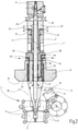
- the Figures 2 to 4 show exemplary embodiments of the device according to the invention. These have additional short inlets and/or outlets for clean, sterile process gas and branch chambers in the extrusion head - and thus in the immediate vicinity of the inner wall of the hose.
- the first embodiment of 2 differs from the one in 1 the prior art shown, on the one hand, in that an exhaust gas duct 35 is additionally provided, which runs parallel to the filling mandrel 1 within the extrusion head 13 and the adjoining section 37 of the support housing 3 over a large part of its length, exits from the section 37 with an exhaust gas outlet 39 and opens into a branch chamber 41 in the extrusion head 13 on the input side.
- the example differs from 2 from the prior art due to the presence of two further process gas feeds 43 and 45, which run from the process gas inlets 42 and 44 and parallel to the filling mandrel 1, through the extrusion head 13 and into the inner space 29 of the hose 19, closely adjacent to the extrusion nozzle 17 .
- a representative amount of gas penetrates from the Space 29 enters the branch chamber 41 and via this into the exhaust gas duct 35 and can therefore be removed at the exhaust gas outlet 39 thereof.
- sample gas sample gas
- a representative composition is continuously available, which can be extracted for analysis purposes, for example to prove that the device meets the required cleanliness class, or - for example in the case of oxygen-sensitive filling goods - the residual oxygen concentration in the hose is sufficiently low is.
- a corresponding measuring device for physical and/or chemical analysis purposes, for example a particle counter, can be connected to the exhaust gas outlet 39 .
- the 3 shows a second embodiment of the device according to the invention.
- This differs from the example from 2 in that two additional exhaust gas ducts 51 and 53 are provided, each starting from an orifice 55 or 57, which is located on the end face 15 of the extrusion head 13 closely adjacent to the extrusion nozzle 17, running parallel to the filling mandrel 1 to exhaust gas outlets 59 or 61 on the housing section 37 extend.
- an additional process gas feed 43 is provided, which starts from the process gas inlet 42 and extends with its main part in the extrusion head 13 parallel to the filling mandrel 1 .
- the additional process gas duct 43 does not lead directly to the inner space 29 in the hose 19, but opens into the branching chamber 41 on the side that is opposite the side where the exhaust gas ducts 35 open out. Part of the sterile process gas passes from the branch chamber 41 into the interior 29 of the tube 19, while another part flows into the guide channel 21 and thus acts as a barrier against potential contamination from the parts of the device located above the branch chamber 41.
- the 4 shows a third embodiment of the device according to the invention. This differs from the example from 3 in that in the branching chamber 41 not only opens into the one exhaust gas duct 35 and the additional process gas supply 43, but that another exhaust gas duct 71 opens into the branching chamber 41. Like the process gas duct 43 , the main part of the additional exhaust duct 71 runs within the extrusion head 13 parallel to the filling mandrel 1 and exits at an exhaust gas outlet 73 in the housing section 37 .
- a device, not shown, that generates negative pressure is connected to the exhaust gas outlet 73, which enables controlled suction and thus the setting of a desired pressure level at which a sample gas quantity for analysis purposes is available during operation at the exhaust gas outlet 39, while at the same time stable guidance is obtained due to the additional process gas introduced of the hose 19 enclosing the space 29.
- the embodiments according to the invention also enable significantly increased gas flow rates compared to the supporting air used exclusively in the prior art.
- the flow profile in the hose interior 29 can thus be adjusted in a targeted manner. This can advantageously be used for the analytical purposes described, for efficient flushing of the tube interior 29 or also for fine adjustment of the temperature of the tube inner surface. This is achieved by pre-tempering the supplied sterile process gas and adjusting its throughput and flow rate and is important for the secure sealing of the filled containers by welding.
- aerosols or explosive vapors of the filling material that can occur during the filling process can be removed safely and directly and can optionally be recorded and analyzed by a measuring device at the exhaust gas outlet 39 .
- the embodiments according to the invention advantageously make it possible to use different and/or differently conditioned process gases simultaneously and selectively. So - for example for filling goods, which can form explosive mixtures - only air via the feed 21 and at the same time via the feeds 43 an - optionally pre-tempered - inert gas such as nitrogen, carbon dioxide or argon are fed. On the one hand, this ensures explosion protection and, on the other hand, reduces the need for inert gas, which leads to lower production costs.
Landscapes
- Engineering & Computer Science (AREA)
- Mechanical Engineering (AREA)
- Manufacturing & Machinery (AREA)
- Basic Packing Technique (AREA)
- Vacuum Packaging (AREA)
- Filling Of Jars Or Cans And Processes For Cleaning And Sealing Jars (AREA)
Description
- Die Erfindung betrifft eine Vorrichtung zum Herstellen und Befüllen von Behältererzeugnissen mit den Merkmalen im Oberbegriff von Anspruch 1.
- Vorrichtungen dieser Art sind Stand der Technik. Das Dokument
WO 2009/ 152979 zeigt eine nach dem bekannten bottelpack®-System arbeitende Vorrichtung, die ein automatisiertes Formen (Blasen oder Vakuumformen), Füllen und Verschließen von Behältnissen auf wirtschaftliche Art und Weise ermöglicht. Wenn sensible Erzeugnisse in die genannten Behältnisse eingefüllt werden sollen, beispielsweise Pharmazeutika, sind die internationalen Standards für die aseptische Verpackung zu erfüllen. Um dem Genüge zu leisten, wird Prozessgas als Stützluft, die zur Stabilisierung der Führung des freien Schlauchabschnitts zwischen Extrusionskopf und Form ins Schlauchinnere eingebracht wird, sterile Luft verwendet, so dass ein sog. Abfüll-Sterilraum (ASR) gebildet ist, in welchem die sterile Luft einen wirksamen Schutz gegen das Eindringen von Keimen bildet, bis nach Beendigen des Füllvorgangs bewegliche Formteile der Form geschlossen werden, um durch einen kombinierten Vakuum-Schweißvorgang den gewünschten Kopfverschluss des Behälters auszubilden. - Die
DE 1 479 698 beschreibt eine Vorrichtung zum Herstellen und Befüllen von Behältererzeugnissen mit den Merkmalen im Oberbegriff von Anspruch 1, bei der zumindest ein Schlauch plastifizierten Kunststoffmaterials in eine geöffnete Form ausgehend von einem Extrusionskopf entlang einer Schlauchführung hinein extrudierbar ist, wobei mittels mindestens eines Fülldornes, der sich zumindest in einer Funktionsstellung durch den Extrusionskopf erstreckt, ein Füllgut in den jeweiligen Behälter einbringbar ist und wobei mittels mindestens einer Prozessgaszuführungseinrichtung Prozessgas ins Innere des Schlauches bringbar ist, wobei die Prozessgaszuführungseinrichtung innerhalb des Extrusionskopfes einen entlang der Außenseite des Fülldorns verlaufenden Führungskanal aufweist. - Weitere Vorrichtungen dieser Art gehen aus der
DE 2 134 166 , derEP 0 361 123 A2 , derDE 10 2013 101 775 A1 , derJP 2013-132861 US 3 251 915 und derDE 1 180 301 hervor. - Ausgehend von diesem Stand der Technik stellt sich die Erfindung die Aufgabe, eine vorteilhafte Vorrichtung der eingangs genannten Gattung zur Verfügung zu stellen, die auf besonders sichere und wirtschaftliche Weise für das Herstellen von Behältnissen für pharmazeutische oder diagnostische Zwecke einsetzbar ist und die, den behördlichen Vorschriften entsprechend, eine zumindest teilkontinuierliche und repräsentative Messung der geforderten Reinraumklasse des Schlauchinneren nahe einer Abfüllposition ermöglicht.
- Erfindungsgemäß ist diese Aufgabe durch eine Vorrichtung gelöst, die die Merkmale des Patentanspruchs 1 in seiner Gesamtheit aufweist.
- Gemäß dem kennzeichnenden Teil des Anspruchs 1 besteht eine wesentliche Besonderheit der Erfindung darin, dass mindestens eine weitere Prozessgaszuführungseinrichtung vorhanden ist, mittels deren zusätzliches Prozessgas über mindestens eine weitere Prozessgaszuführung ins Innere des Schlauches nahe dessen Innenseite an der Stelle des Austritts aus dem Extrusionskopf bringbar ist.
- Dadurch ist eine - gegenüber der reinen Stützluft gemäß dem Stand der Technik - wesentlich erhöhte Gasmenge in den Schlauch einbringbar und somit eine besonders effektive Regelung zur Stabilisierung der Schlauchausformung und -führung möglich. Ferner ist damit durch gezielte Temperierung des Prozessgases auch eine direkte Einflussnahme auf die Temperatur der Schlauchinnenseite realisierbar. Überdies lässt sich durch Wahl von Durchsatz und Strömungsgeschwindigkeit des Prozessgases das Strömungsprofil im Inneren des Schlauches einstellen. Bei Einbringen von zusätzlichem Prozessgas kann mit Vorteil mindestens eine weitere Abgasführung vorhanden sein, mittels deren Prozessgas zusätzlich zu der Analysemenge abführbar ist.
- Es ist ferner vorgesehen, dass zumindest ein Teil des zusätzlich eingebrachten Prozessgases ausgehend vom Inneren des Schlauchs entlang mindestens einer vorgebbaren Abgasführung, die von der jeweiligen Prozessgaszuführung separiert ist, durch den Extrusionskopf hindurch abgeführt ist. Dadurch steht, ohne den Herstellvorgang der Vorrichtung unterbrechen zu müssen, über die Abgasführung eine aus dem Raum innerhalb des Schlauches stammende Prüfgasmenge zur Verfügung, die beispielsweise für den Nachweis der Einhaltung der Vorgaben betreffend Reinraumklasse, den Restsauerstoffgehalt oder Ähnlichem analysierbar ist. Als Prozessgas kann sterile Luft oder - beispielsweise bei sauerstoffempfindlichen Füllgütern - ein Inertgas, wie Stickstoff oder Argon, verwendet werden.
- Dabei kann die Anordnung mit Vorteil so getroffen sein, dass zumindest teilweise die Anzahl der eingesetzten Abgasführungen um mindestens eins größer ist als die Anzahl der Prozessgaszuführungen.
- Mit Vorteil kann an mindestens eine der Abgasführungen eine Unterdruck erzeugende Einrichtung angeschlossen sein, die eine geregelte Absaugung von Prozessgas in einem für die Stabilisierung der Schlauchformung und -führung optimalen Ausmaß ermöglicht, sowie den Gasanalysegeräten, Partikelzählern etc. konstante, geregelte Gasmengen liefert.
- Bei besonders vorteilhaften Ausführungsbeispielen verläuft die jeweils eine Prozessgaszuführung zumindest teilweise zwischen dem jeweiligen Fülldorn und einem Trägergehäuse, in dem der Fülldorn längsverfahrbar geführt ist, wobei Teile dieser einen Prozessgasführung in sich abzweigende Funktionskanäle, im Trägergehäuse verlaufend, übergehen, die sperrend den Eintritt von potentiell unreiner Umgebungsluft in die Prozessgasführung und damit ins Schlauchinnere vermeiden.
- Mit Vorteil kann die Anordnung so getroffen sein, dass mindestens eine Abgasführung, die für physikalische und/ oder chemische Analysezwecke vorgesehen ist, mit ihrem einen freien Ende in eine Abzweigkammer im Extrusionskopf ausmündet, die von dem Fülldorn durchgriffen ist, und in die zumindest das Prozessgas aus der Innenseite des Schlauchs eindringt.
- Vorzugsweise mündet das eine freie Ende der weiteren Prozessgaszuführung in die Abzweigkammer auf der Seite ein, die der Seite gegenüberliegt, auf der die eine Abgasführung in die Abzweigkammer einmündet. In die Abzweigkammer kann mindestens eine weitere Prozessgaszuführung seitlich einmünden.
- Ferner kann hierbei mindestens eine der Abgasführungen vorzugsweise an die Unterdruck erzeugende, regelbare Einrichtung angeschlossen sein und seitlich wie parallel zu der einen weiteren Prozessgaszuführung in die Abzweigkammer einmünden.
- Mit Vorteil kann auch zumindest eine Abgasführung auf die Innenseite des Schlauchs ausmünden und kann kanalartig den Extrusionskopf durchgreifen sowie parallel zu dem Fülldorn verlaufend angeordnet sein.
- Nachstehend ist die Erfindung anhand von in der Zeichnung dargestellten Ausführungsbeispielen im Einzelnen erläutert. Es zeigen:
- Fig. 1
- einen Vertikalschnitt eines Teils einer nach dem bottelpack®-System arbeitenden Vorrichtung gemäß dem Stand der Technik, wobei lediglich der Bereich der Fülldorne dargestellt ist, deren einziger Sichtbarer sich mit seinem füllnadelartigen Ende in eine Form mit beweglichen Formteilen hinein erstreckt;
- Fig. 2
- eine der
Fig. 1 entsprechende Darstellung, wobei ein erstes Ausführungsbeispiel der erfindungsgemäßen Vorrichtung dargestellt ist; und - Fig. 3 und 4
- entsprechende Darstellungen eines zweiten bzw. dritten Ausführungsbeispiels der erfindungsgemäßen Vorrichtung.
- Die
Fig. 1 zeigt von einer bekannten Vorrichtung zum Herstellen und Befüllen von Behältererzeugnissen durch Blas- oder Vakuumformen ein Vorrichtungsteil, das im Wesentlichen dem Vorrichtungsteil entspricht, wie es in Fig. 5 der zum Stand der Technik erwähntenWO 2009/152 979 A1 gezeigt ist. Wie in dieser Figur ist von einer Mehrzahl von Fülleinrichtungen, die in einer zur Zeichnungsebene senkrechten Reihe angeordnet sind, lediglich ein einziger Fülldorn 1 sichtbar, der in der bei derartigen Vorrichtungen üblichen Weise in einem Trägergehäuse 3 in unterschiedliche, gewählte Betriebsstellungen gesteuert verfahrbar gelagert ist. DieFig. 1 zeigt den sichtbaren Fülldorn 1 in einer vorgeschobenen Betriebsstellung für einen Füllvorgang, wobei der füllnadelartig verjüngte Endabschnitt 5 in eine kopfseitig noch nicht geschlossene Form 7 vorgeschoben ist. In einer Art Karussell-Anordnung werden hierbei Einzel-Formteile 9 auf einer fiktiven Kreisbogenbahn 10 paarweise aufeinander zu bewegt, um eine geschlossene Herstellform zu bilden, und zum Öffnen der Form wieder auseinanderbewegt. Für eine dosierte Abgabe von Füllgut aus dem Endabschnitt 5 weist jeder Fülldorn 1 einen zentral gelegenen Füllkanal 11 auf. In der bei derartigen Vorrichtungen üblichen Weise sind die Füllkanäle 11 von einer (nicht gezeigten) zentralen Füllgutleitung her mit steuerbaren Dosiseinheiten des jeweils einzufüllenden Erzeugnisses belieferbar. - An dem Trägergehäuse 3 ist ein Extrusionskopf 13 - oft auch als Schlauchkopf bezeichnet - gelagert, der an seiner Stirnfläche 15 in an sich bekannter Weise eine ringförmige Extrusionsdüse 17 aufweist, aus der im Betrieb ein Schlauch 19 austritt, der aus plastifiziertem Kunststoffmaterial gebildet ist, das dem Extrusionskopf 13 von einer (nicht gezeigten) Extrudereinrichtung her zugeführt wird. Da derartige Extrudereinrichtungen, ebenso wie die Bauweise des Extrusionskopfes 13, an sich bekannt sind, beispielsweise in Form von nach dem bottelpack®-Verfahren arbeitenden Einrichtungen, erübrigt sich eine nähere Erläuterung der diesbezüglichen Einzelheiten.
- Zur Stabilisierung der freien Schlauchformung und -führung im Verlauf des Schlauchs 19 von der Extrusionsdüse 17 in die Form 7 ist in bekannter Weise eine sogenannte Prozessgaszuführungseinrichtung respektive Stützlufteinrichtung vorgesehen. Diese weist einen innerhalb des Trägergehäuses 3 und des Extrusionskopfes 13 entlang der Außenseite des Fülldorns 1 verlaufenden Führungskanal 21 auf, der sich, von einem Eingang 23 ausgehend, der sich an einem hülsenartigen Endteil 25 des Trägergehäuses 3 befindet, entlang der Außenseite des jeweiligen Fülldorns 1 bis zu einer Austrittsmündung 27 an der Stirnfläche 15 des Extrusionskopfes 13 erstreckt. Durch Einströmen sterilen Prozessgases oder steriler Stützluft über die Austrittsmündung 27 ins Innere des Schlauchs 19, der in seinem Verlauf vom Extrusionskopf 13 in die Form 7 hinein einen abgeschlossenen Raum 29 bildet, bildet das Schlauchinnere den Abfüll-Sterilraum, innerhalb dessen der gesamte Produktionsvorgang durchgeführt wird, d.h. bis zur Bildung des Kopfverschlusses am befüllten Behälter, was durch Schließen der betreffenden Kopfbacken der Form 7 durchgeführt wird. Da entsprechende Mechanismen der Form 7 an sich bekannt sind, ist in der Zeichnung die als Ganzes mit 7 bezeichnete Form lediglich schematisch vereinfacht, also ohne gesonderte Darstellung von Hauptformteilen und Kopfformteilen, wiedergegeben. Um den Führungskanal 21 gegen den Eintritt von Umgebungsluft abzuschirmen, sind im Endteil 25 des Trägergehäuses 3 quer verlaufende Funktionskanäle 31 vorgesehen, die mit dem Führungskanal 21 in Verbindung sind und über die Stützluft oder Prozessgas frei abströmen kann. Zusätzliche freie Abströmkanäle 33 für Prozessgas sind am äußeren Ende des Endteils 25 des Trägergehäuses 3 vorgesehen.
- Der Gasraum 29 innerhalb des Schlauches 19 ist für analytische Zwecke nicht zugänglich, auch erschweren die große Länge des prozessgaszuführenden Kanals 21 und die geringen Prozessgas- oder Stützluftvolumenflüsse eine produktionssichere und präzise Steuerung der Schlauchausbildung.
- Die
Fig. 2 bis 4 zeigen Ausführungsbeispiele der erfindungsgemäßen Vorrichtung. Diese weisen im Extrusionskopf - und damit in unmittelbarer Nähe zur Innenwand des Schlauches - zusätzliche kurze Zu- und/oder Abführungen für reines, steriles Prozessgas sowie Abzweigkammern auf. Das erste Ausführungsbeispiel vonFig. 2 unterscheidet sich von dem inFig. 1 gezeigten Stand der Technik zum einen dadurch, dass zusätzlich eine Abgasführung 35 vorgesehen ist, die auf einem Großteil ihrer Länge parallel zum Fülldorn 1 innerhalb des Extrusionskopfes 13 und des anschließenden Abschnitts 37 des Trägergehäuses 3 verläuft, mit einem Abgasausgang 39 aus dem Abschnitt 37 austritt und eingangsseitig in eine Abzweigkammer 41 im Extrusionskopf 13 mündet. Zum anderen unterscheidet sich das Beispiel vonFig. 2 vom Stand der Technik durch das Vorhandensein zweier weiterer Prozessgaszuführungen 43 und 45, die von Prozessgaseingängen 42 bzw. 44 her und zum Fülldorn 1 parallel, durch den Extrusionskopf 13 verlaufen und in den inneren Raum 29 des Schlauches 19, zur Extrusionsdüse 17 eng benachbart, einmünden. Durch geregeltes Einbringen der zusätzlichen Prozessgasströme dringt eine repräsentative Gasmenge aus dem Raum 29 in die Abzweigkammer 41 und über diese in die Abgasführung 35 ein und ist dadurch an deren Abgasausgang 39 abnehmbar. Somit steht während des Betriebs der Vorrichtung kontinuierlich eine Gasmenge (Probegas) mit repräsentativer Zusammensetzung zur Verfügung, die für Analysezwecke absaugbar ist, beispielsweise um nachzuweisen, dass die Vorrichtung die geforderte Reinheitsklasse erfüllt, oder - beispielsweise bei sauerstoffempfindlichen Füllgütern - die Restsauerstoffkonzentration im Schlauch ausreichend niedrig ist. An den Abgasausgang 39 kann hierfür ein entsprechendes Messgerät (nicht abgebildet), für physikalische und/oder chemische Analysezwecke, beispielsweise ein Partikelzähler, angeschlossen werden. - Die
Fig. 3 zeigt ein zweites Ausführungsbeispiel der erfindungsgemäßen Vorrichtung. Dieses unterscheidet sich vom Beispiel vonFig. 2 dadurch, dass zwei zusätzliche Abgasführungen 51 und 53 vorgesehen sind, die jeweils von einer Mündung 55 bzw. 57 ausgehend, die an der Stirnfläche 15 des Extrusionskopfes 13 eng benachbart zur Extrusionsdüse 17 gelegen sind, sich parallel zum Fülldorn 1 verlaufend zu Abgasausgängen 59 bzw. 61 am Gehäuseabschnitt 37 erstrecken. Wie beim Beispiel vonFig. 2 ist eine zusätzliche Prozessgaszuführung 43 vorgesehen, die vom Prozessgaseingang 42 ausgeht und sich mit ihrem Hauptteil im Extrusionskopf 13 parallel zum Fülldorn 1 erstreckt. Ein weiterer Unterschied zum Beispiel vonFig. 2 besteht darin, dass die zusätzliche Prozessgasführung 43 nicht direkt zum Innenraum 29 im Schlauch 19 führt, sondern in die Abzweigkammer 41 auf der Seite einmündet, die der Seite der Einmündung der Abgasführungen 35 gegenüberliegend ist. Von der Abzweigkammer 41 tritt ein Teil des sterilen Prozessgases in den Innenraum 29 des Schlauches 19 über, während ein anderer Teil in den Führungskanal 21 überströmt und somit als Barriere gegen potentielle Verunreinigungen aus den oberhalb der Abzweigkammer 41 befindlichen Teilen der Vorrichtung wirkt. - Die
Fig. 4 zeigt ein drittes Ausführungsbeispiel der erfindungsgemäßen Vorrichtung. Dieses unterscheidet sich vom Beispiel vonFig. 3 dadurch, dass in die Abzweigkammer 41 nicht nur die eine Abgasführung 35 und die zusätzliche Prozessgaszuführung 43 einmünden, sondern dass eine weitere Abgasführung 71 in die Abzweigkammer 41 einmündet. Wie die Prozessgasführung 43 verläuft die zusätzliche Abgasführung 71 mit ihrem Hauptteil innerhalb des Extrusionskopfes 13 parallel zum Fülldorn 1 und tritt an einem Abgasausgang 73 im Gehäuseabschnitt 37 aus. Am Abgasausgang 73 ist eine nicht gezeigte Unterdruck erzeugende Einrichtung angeschlossen, die eine gesteuerte Absaugung und damit die Einstellung eines gewünschten Druckniveaus ermöglicht, bei dem im Betrieb am Abgasausgang 39 eine Probegasmenge für Analysezwecke zur Verfügung steht, bei gleichzeitig durch das eingebrachte zusätzliche Prozessgas erhaltener stabiler Führung des den Raum 29 einschließenden Schlauches 19. - Die erfindungsgemäßen Ausführungen ermöglichen ferner - gegenüber der im Stand der Technik ausschließlichen verwendeten Stützluft - deutlich erhöhte Gasflussraten. Somit kann das Strömungsprofil im Schlauchinneren 29 gezielt eingestellt werden. Dies ist vorteilhaft verwendbar für die beschriebenen analytischen Zwecke, zur effizienten Spülung des Schlauchinneren 29 oder auch zur Feineinstellung der Temperatur der Schlauchinnenoberfläche. Dies gelingt durch die Vortemperierung des zugeführten sterilen Prozessgases und der Einstellung von dessen Durchsatz und Strömungsgeschwindigkeit und ist für das sichere Verschließen der befüllten Behälter durch Verschweißen von Bedeutung.
- Durch die erfindungsgemäß erhöhten Gasdurchsätze lassen sich beispielsweise Aerosole oder explosive Dämpfe des Füllgutes, die beim Füllvorgang auftreten können, sicher und direkt abführen und können optional durch ein Messgerät am Abgasausgang 39 erfasst und analysiert werden.
- Überdies ermöglichen es die erfindungsgemäßen Ausführungen vorteilhaft verschiedene und/oder verschiedenartig konditionierte Prozessgase gleichzeitig und selektiv zu verwenden. So kann - beispielsweise für Füllgüter, die explosive Gemische bilden können - über die Zuführung 21 lediglich Luft und gleichzeitig über die Zuführungen 43 ein - optional vortemperiertes - Inertgas wie Stickstoff, Kohlendioxid oder Argon zugeführt werden. Dies sichert zum einen den Explosionsschutz und reduziert zum andern den Bedarf an Inertgas, was zu geringeren Produktionskosten führt.
Claims (14)
- Vorrichtung zum Herstellen und Befüllen von Behältererzeugnissen, bei der zumindest ein Schlauch (19) plastifizierten Kunststoffmaterials in eine geöffnete Form (7) ausgehend von einem Extrusionskopf (13) entlang einer Schlauchführung hinein extrudierbar ist, wobei mittels mindestens eines Fülldornes (1), der sich zumindest in einer Funktionsstellung durch den Extrusionskopf (13) erstreckt, ein Füllgut in den jeweiligen Behälter einbringbar ist und wobei mittels mindestens einer Prozessgaszuführungseinrichtung (21, 23) Prozessgas ins Innere des Schlauches (19) bringbar ist, wobei die Prozessgaszuführungseinrichtung (21, 23) einen innerhalb des Extrusionskopfes (13) entlang der Außenseite des Fülldorns (1) verlaufenden Führungskanal (21) aufweist, wobei zumindest ein Teil des eingebrachten Prozessgases entlang mindestens einer vorgebbaren Abgasführung (35), die von dem jeweiligen Führungskanal (21) separiert ist, durch den Extrusionskopf (13) hindurch abgeführt ist, dadurch gekennzeichnet, dass mindestens eine weitere Prozessgaszuführungseinrichtung vorhanden ist, mittels deren zusätzliches Prozessgas über mindestens eine weitere Prozessgaszuführung (43) ins Innere des Schlauches (19) nahe dessen Innenseite (29) an der Stelle des Austritts aus dem Extrusionskopf (13) bringbar ist.
- Vorrichtung nach Anspruch 1, dadurch gekennzeichnet, dass das Prozessgas vortemperierbar zugeführt werden kann.
- Vorrichtung nach Anspruch 1 oder 2, dadurch gekennzeichnet, dass über den Führungskanal (21) und die Prozessgaszuführung (43) zumindest teilweise gleichzeitig verschiedenartige und/oder verschieden konditionierte Prozessgase, bevorzugt Luft und ein Inertgas, einbringbar sind.
- Vorrichtung nach einem der vorstehenden Ansprüche, dadurch gekennzeichnet, dass mindestens eine weitere Abgasführung (51, 53) vorhanden ist, mittels deren das Prozessgas zumindest teilweise aus dem Inneren des Schlauches (19) bevorzugt von dessen Innenseite (29) abführbar ist.
- Vorrichtung nach Anspruch 4, dadurch gekennzeichnet, dass zumindest teilweise die Anzahl der eingesetzten Abgasführungen (21, 35, 51, 53, 71) um mindestens eins größer ist als die Anzahl der Prozessgaszuführungen (43, 45).
- Vorrichtung nach einem der vorstehenden Ansprüche, dadurch gekennzeichnet, dass an mindestens eine (35, 71) der Abgasführungen (35, 51, 53, 71) eine bevorzugt regelbare Unterdruck erzeugende Einrichtung angeschlossen ist.
- Vorrichtung nach einem der vorstehenden Ansprüche, dadurch gekennzeichnet, dass an mindestens eine (35) der Abgasführungen (35, 51, 53, 71) ein Messgerät, insbesondere zur physikalischen und/ oder chemischen Analyse, anschließbar ist.
- Vorrichtung nach Anspruch 7, dadurch gekennzeichnet, dass es sich bei dem Messgerät um ein Partikelzählgerät handelt.
- Vorrichtung nach einem der vorstehenden Ansprüche, dadurch gekennzeichnet, dass zumindest ein Teilstrom des Prozessgases aus einer Abzweigkammer (41) in den jeweiligen Führungskanal (21) eintritt, der zumindest teilweise zwischen dem jeweiligen Fülldorn (1) und einem Trägergehäuse (3) verläuft, in dem der Fülldorn (1) längsverfahrbar geführt ist, und über Funktionskanäle (31), im Trägergehäuse (3) verlaufend, austritt und sperrend den Eintritt von Umgebungsluft verhindert.
- Vorrichtung nach Anspruch 9, dadurch gekennzeichnet, dass mindestens eine Abgasführung (35) mit ihrem einen Ende in die Abzweigkammer (41) im Extrusionskopf (13) ausmündet, die von dem Fülldorn (1) durchgriffen ist und in die zumindest das Prozessgas aus dem Inneren des Schlauches (19) eindringt.
- Vorrichtung nach Anspruch 9 oder 10, dadurch gekennzeichnet, dass das eine Ende der weiteren Prozessgasführung (43) in die Abzweigkammer (41) auf der Seite einmündet, die der Seite gegenüberliegt, auf der die eine Abgasführung (35) in die Abzweigkammer (41) einmündet.
- Vorrichtung nach einem der Ansprüche 9 bis 11, dadurch gekennzeichnet, dass die mindestens eine weitere Abgasführung (71) seitlich in die Abzweigkammer (41) einmündet.
- Vorrichtung nach einem der Ansprüche 9 bis 12, dadurch gekennzeichnet, dass mindestens eine (35, 71) der Abgasführungen (35, 51, 53, 71) vorzugsweise an die Unterdruck erzeugende Einrichtung angeschlossen ist und seitlich wie parallel zu der einen weiteren Prozessgasführung (43) in die Abzweigkammer (41) einmündet.
- Vorrichtung nach einem der vorstehenden Ansprüche, dadurch gekennzeichnet, dass zumindest eine Abgasführung (51, 53) auf die Innenseite (29) des Schlauches (19) ausmündet und kanalartig den Extrusionskopf (13) durchgreift sowie parallel zu den Fülldornen (1) verlaufend angeordnet ist.
Applications Claiming Priority (2)
| Application Number | Priority Date | Filing Date | Title |
|---|---|---|---|
| DE102017008803.9A DE102017008803A1 (de) | 2017-09-20 | 2017-09-20 | Vorrichtung zum Herstellen und Befüllen von Behältererzeugnissen |
| PCT/EP2018/073958 WO2019057502A1 (de) | 2017-09-20 | 2018-09-06 | Vorrichtung zum herstellen und befüllen von behältererzeugnissen |
Publications (2)
| Publication Number | Publication Date |
|---|---|
| EP3684696A1 EP3684696A1 (de) | 2020-07-29 |
| EP3684696B1 true EP3684696B1 (de) | 2022-03-23 |
Family
ID=63556307
Family Applications (1)
| Application Number | Title | Priority Date | Filing Date |
|---|---|---|---|
| EP18768830.4A Active EP3684696B1 (de) | 2017-09-20 | 2018-09-06 | Vorrichtung zum herstellen und befüllen von behältererzeugnissen |
Country Status (8)
| Country | Link |
|---|---|
| US (1) | US12485599B2 (de) |
| EP (1) | EP3684696B1 (de) |
| KR (1) | KR102557523B1 (de) |
| CN (1) | CN111094133B (de) |
| BR (1) | BR112020004359B1 (de) |
| DE (1) | DE102017008803A1 (de) |
| ES (1) | ES2914730T3 (de) |
| WO (1) | WO2019057502A1 (de) |
Families Citing this family (3)
| Publication number | Priority date | Publication date | Assignee | Title |
|---|---|---|---|---|
| DE102021117604A1 (de) * | 2021-07-07 | 2023-01-12 | Collin Lab & Pilot Solutions Gmbh | Extrusionsvorrichtung und Verfahren zur Herstellung eines einen Hohlraum aufweisenden Gegenstandes |
| DE102023004512A1 (de) * | 2023-11-08 | 2025-05-08 | Kocher-Plastik Maschinenbau Gmbh | Vorrichtung zum Blasformen und Befüllen von Behältnissen |
| DE102024002690A1 (de) | 2024-08-19 | 2026-02-19 | Rommelag Engineering Gmbh | System |
Citations (2)
| Publication number | Priority date | Publication date | Assignee | Title |
|---|---|---|---|---|
| DE1180301B (de) * | 1961-07-17 | 1964-10-22 | Schmalbach Ag J A | Verfahren und Vorrichtung zum konti-nuierlichen Herstellen gefuellter und verschlos-sener Behaelter aus thermoplastischem Kunststoff |
| DE1479698A1 (de) * | 1964-07-10 | 1969-05-29 | Shell Int Research | Verfahren und Vorrichtung zum Formen von Flaschen |
Family Cites Families (20)
| Publication number | Priority date | Publication date | Assignee | Title |
|---|---|---|---|---|
| NL284490A (de) | 1961-10-25 | 1900-01-01 | ||
| DE2134166A1 (de) * | 1971-07-09 | 1973-01-18 | Pmd Entwicklungswerk | Verfahren und vorrichtung zum herstellen von hohlkoerpern im blas- bzw. blasfuellverfahren |
| GB1474044A (en) * | 1974-12-03 | 1977-05-18 | Ici Ltd | Plastics container manufacture |
| US4244913A (en) * | 1979-05-25 | 1981-01-13 | Ryder Leonard B | Method for injection blow molding |
| IT1188390B (it) * | 1986-02-14 | 1988-01-07 | Tetra Dev Co | Metodo e complesso in macchine di confezionamento |
| US4968539A (en) | 1987-12-01 | 1990-11-06 | Lion Corporation | Liquid crystal membrane |
| DE3832566A1 (de) * | 1988-09-24 | 1990-04-05 | Bernd Hansen | Verfahren zum herstellen gefuellter fluessigkeitsbehaelter aus thermoplastischem kunststoff sowie extrusionskopf |
| JPH04223128A (ja) * | 1990-12-26 | 1992-08-13 | Mazda Motor Corp | 樹脂成形品のブロー成形方法 |
| DE4205655C2 (de) * | 1992-02-25 | 1999-12-16 | Bosch Gmbh Robert | Verfahren zum Sterilisieren einer Verpackungsmaschine und Vorrichtung zum Durchführen des Verfahrens |
| US5862840A (en) * | 1994-03-21 | 1999-01-26 | Hansen; Bernd | Device for sterile filling of containers |
| FR2765515B1 (fr) * | 1997-07-04 | 1999-09-24 | Grosfillex Sarl | Dispositif et procede de fabrication d'un objet en matiere plastique par soufflage |
| JP2000289097A (ja) * | 1999-04-13 | 2000-10-17 | Nakkusu Kk | 容器成形と同時に内容物を充填する成形方法並びにその装置 |
| US6635216B2 (en) * | 2001-05-18 | 2003-10-21 | Graham Engineering Corporation | Blow molding machine and method |
| DE102007015078A1 (de) * | 2007-03-29 | 2008-10-02 | Bernd Hansen | Vorrichtung zum Minimieren des Sauerstoffgehaltes |
| DE102008028754A1 (de) | 2008-06-17 | 2009-12-24 | Bernd Hansen | Vorrichtung zum Herstellen und Befüllen von Behältern |
| JP5747413B2 (ja) * | 2011-12-27 | 2015-07-15 | 株式会社吉野工業所 | 2軸延伸ブロー成形装置及び容器の製造方法 |
| US9440754B2 (en) * | 2012-03-29 | 2016-09-13 | R.P. Scherer Technologies, Llc | Three circuit fill system for blow fill seal containers |
| DE102013101642A1 (de) * | 2013-02-19 | 2014-08-21 | Khs Gmbh | Verfahren und Vorrichtung zum Herstellen und Füllen von Behältern |
| DE102013101775A1 (de) * | 2013-02-22 | 2014-08-28 | Khs Gmbh | Verfahren und Vorrichtung zur Herstellung und Füllen von Behältern |
| JP6184851B2 (ja) * | 2013-11-28 | 2017-08-23 | 株式会社吉野工業所 | ブロー成形用金型 |
-
2017
- 2017-09-20 DE DE102017008803.9A patent/DE102017008803A1/de not_active Withdrawn
-
2018
- 2018-09-06 CN CN201880060674.7A patent/CN111094133B/zh active Active
- 2018-09-06 KR KR1020207008624A patent/KR102557523B1/ko active Active
- 2018-09-06 WO PCT/EP2018/073958 patent/WO2019057502A1/de not_active Ceased
- 2018-09-06 BR BR112020004359-1A patent/BR112020004359B1/pt active IP Right Grant
- 2018-09-06 ES ES18768830T patent/ES2914730T3/es active Active
- 2018-09-06 EP EP18768830.4A patent/EP3684696B1/de active Active
- 2018-09-06 US US16/648,371 patent/US12485599B2/en active Active
Patent Citations (2)
| Publication number | Priority date | Publication date | Assignee | Title |
|---|---|---|---|---|
| DE1180301B (de) * | 1961-07-17 | 1964-10-22 | Schmalbach Ag J A | Verfahren und Vorrichtung zum konti-nuierlichen Herstellen gefuellter und verschlos-sener Behaelter aus thermoplastischem Kunststoff |
| DE1479698A1 (de) * | 1964-07-10 | 1969-05-29 | Shell Int Research | Verfahren und Vorrichtung zum Formen von Flaschen |
Also Published As
| Publication number | Publication date |
|---|---|
| KR20200054995A (ko) | 2020-05-20 |
| DE102017008803A1 (de) | 2019-03-21 |
| ES2914730T3 (es) | 2022-06-15 |
| EP3684696A1 (de) | 2020-07-29 |
| WO2019057502A1 (de) | 2019-03-28 |
| US12485599B2 (en) | 2025-12-02 |
| BR112020004359A2 (pt) | 2020-09-08 |
| CN111094133A (zh) | 2020-05-01 |
| BR112020004359B1 (pt) | 2023-12-26 |
| CN111094133B (zh) | 2022-01-04 |
| KR102557523B1 (ko) | 2023-07-24 |
| US20200230860A1 (en) | 2020-07-23 |
Similar Documents
| Publication | Publication Date | Title |
|---|---|---|
| WO2009152979A1 (de) | Vorrichtung zum herstellen und befüllen von behältern | |
| EP4313540B1 (de) | Vorrichtung und verfahren zum herstellen von geformten, befüllten und verschlossenen behältererzeugnissen aus kunststoffmaterial | |
| EP2125524B1 (de) | Vorrichtung zum minimieren des sauerstoffgehaltes | |
| EP1183145B1 (de) | Vorrichtung zum herstellen von extrusionsblasgeformten behältern mit mindestens zwei kammern | |
| WO2019052674A1 (de) | Vorrichtung und verfahren zur thermischen oder thermo-chemischen behandlung von material | |
| EP2687478B1 (de) | Vorrichtung und Verfahren zur Behandlung von Verschlüssen für Behälter | |
| EP3684695B1 (de) | Vorrichtung zum herstellen und befüllen von behältern | |
| EP2455106A1 (de) | Verdampfer zum Sterilisieren von Kunststoffbehältern | |
| WO2016173828A1 (de) | Verfahren und vorrichtung zum schmelzspinnen und abkühlen von multifilen fäden | |
| EP2746029A1 (de) | Vorrichtung und Verfahren zum Sterilisieren von Behältnissen | |
| EP2641487B1 (de) | Messanordnung zum Messen von Strängen und/oder Strangabschnitten sowie Strangeinheit mit einer solchen Messanordnung und Verfahren zum Messen | |
| EP3684696A1 (de) | Vorrichtung zum herstellen und befüllen von behältererzeugnissen | |
| EP0534096B1 (de) | Verfahren und Vorrichtung zum Untersuchen von Behältnissen auf Fremdstoffe | |
| EP2665849B1 (de) | Vorrichtung zum abkühlen einer vielzahl synthetischer fäden | |
| EP3901333A1 (de) | Herstellung von filamenten mit kontrollierter gasströmung | |
| EP3717397B1 (de) | Verschliessvorrichtung zum begasen und verschliessen von behältern, die eine einfüllöffnung aufweisen | |
| DE102024002690A1 (de) | System | |
| EP4572937A1 (de) | Vorrichtung und verfahren zum nachbehandeln von behältererzeugnissen | |
| DE102024001609A1 (de) | Vorrichtung | |
| DE10065652A1 (de) | Vorrichtung zur Herstellung von Kunststoffbehältern mittels Streckblasformen | |
| DE10237730A1 (de) | Vorrichtung zum Kalibrieren von Kunststoffprofilen |
Legal Events
| Date | Code | Title | Description |
|---|---|---|---|
| STAA | Information on the status of an ep patent application or granted ep patent |
Free format text: STATUS: UNKNOWN |
|
| STAA | Information on the status of an ep patent application or granted ep patent |
Free format text: STATUS: THE INTERNATIONAL PUBLICATION HAS BEEN MADE |
|
| PUAI | Public reference made under article 153(3) epc to a published international application that has entered the european phase |
Free format text: ORIGINAL CODE: 0009012 |
|
| STAA | Information on the status of an ep patent application or granted ep patent |
Free format text: STATUS: REQUEST FOR EXAMINATION WAS MADE |
|
| 17P | Request for examination filed |
Effective date: 20200420 |
|
| AK | Designated contracting states |
Kind code of ref document: A1 Designated state(s): AL AT BE BG CH CY CZ DE DK EE ES FI FR GB GR HR HU IE IS IT LI LT LU LV MC MK MT NL NO PL PT RO RS SE SI SK SM TR |
|
| AX | Request for extension of the european patent |
Extension state: BA ME |
|
| DAV | Request for validation of the european patent (deleted) | ||
| DAX | Request for extension of the european patent (deleted) | ||
| STAA | Information on the status of an ep patent application or granted ep patent |
Free format text: STATUS: EXAMINATION IS IN PROGRESS |
|
| 17Q | First examination report despatched |
Effective date: 20210504 |
|
| GRAP | Despatch of communication of intention to grant a patent |
Free format text: ORIGINAL CODE: EPIDOSNIGR1 |
|
| STAA | Information on the status of an ep patent application or granted ep patent |
Free format text: STATUS: GRANT OF PATENT IS INTENDED |
|
| INTG | Intention to grant announced |
Effective date: 20211214 |
|
| GRAS | Grant fee paid |
Free format text: ORIGINAL CODE: EPIDOSNIGR3 |
|
| GRAA | (expected) grant |
Free format text: ORIGINAL CODE: 0009210 |
|
| STAA | Information on the status of an ep patent application or granted ep patent |
Free format text: STATUS: THE PATENT HAS BEEN GRANTED |
|
| AK | Designated contracting states |
Kind code of ref document: B1 Designated state(s): AL AT BE BG CH CY CZ DE DK EE ES FI FR GB GR HR HU IE IS IT LI LT LU LV MC MK MT NL NO PL PT RO RS SE SI SK SM TR |
|
| REG | Reference to a national code |
Ref country code: GB Ref legal event code: FG4D Free format text: NOT ENGLISH |
|
| REG | Reference to a national code |
Ref country code: CH Ref legal event code: EP |
|
| REG | Reference to a national code |
Ref country code: IE Ref legal event code: FG4D Free format text: LANGUAGE OF EP DOCUMENT: GERMAN |
|
| REG | Reference to a national code |
Ref country code: DE Ref legal event code: R096 Ref document number: 502018009189 Country of ref document: DE |
|
| REG | Reference to a national code |
Ref country code: AT Ref legal event code: REF Ref document number: 1477289 Country of ref document: AT Kind code of ref document: T Effective date: 20220415 |
|
| REG | Reference to a national code |
Ref country code: SE Ref legal event code: TRGR |
|
| REG | Reference to a national code |
Ref country code: ES Ref legal event code: FG2A Ref document number: 2914730 Country of ref document: ES Kind code of ref document: T3 Effective date: 20220615 |
|
| REG | Reference to a national code |
Ref country code: LT Ref legal event code: MG9D |
|
| REG | Reference to a national code |
Ref country code: NL Ref legal event code: MP Effective date: 20220323 |
|
| PG25 | Lapsed in a contracting state [announced via postgrant information from national office to epo] |
Ref country code: RS Free format text: LAPSE BECAUSE OF FAILURE TO SUBMIT A TRANSLATION OF THE DESCRIPTION OR TO PAY THE FEE WITHIN THE PRESCRIBED TIME-LIMIT Effective date: 20220323 Ref country code: NO Free format text: LAPSE BECAUSE OF FAILURE TO SUBMIT A TRANSLATION OF THE DESCRIPTION OR TO PAY THE FEE WITHIN THE PRESCRIBED TIME-LIMIT Effective date: 20220623 Ref country code: LT Free format text: LAPSE BECAUSE OF FAILURE TO SUBMIT A TRANSLATION OF THE DESCRIPTION OR TO PAY THE FEE WITHIN THE PRESCRIBED TIME-LIMIT Effective date: 20220323 Ref country code: HR Free format text: LAPSE BECAUSE OF FAILURE TO SUBMIT A TRANSLATION OF THE DESCRIPTION OR TO PAY THE FEE WITHIN THE PRESCRIBED TIME-LIMIT Effective date: 20220323 Ref country code: BG Free format text: LAPSE BECAUSE OF FAILURE TO SUBMIT A TRANSLATION OF THE DESCRIPTION OR TO PAY THE FEE WITHIN THE PRESCRIBED TIME-LIMIT Effective date: 20220623 |
|
| PG25 | Lapsed in a contracting state [announced via postgrant information from national office to epo] |
Ref country code: LV Free format text: LAPSE BECAUSE OF FAILURE TO SUBMIT A TRANSLATION OF THE DESCRIPTION OR TO PAY THE FEE WITHIN THE PRESCRIBED TIME-LIMIT Effective date: 20220323 Ref country code: GR Free format text: LAPSE BECAUSE OF FAILURE TO SUBMIT A TRANSLATION OF THE DESCRIPTION OR TO PAY THE FEE WITHIN THE PRESCRIBED TIME-LIMIT Effective date: 20220624 Ref country code: FI Free format text: LAPSE BECAUSE OF FAILURE TO SUBMIT A TRANSLATION OF THE DESCRIPTION OR TO PAY THE FEE WITHIN THE PRESCRIBED TIME-LIMIT Effective date: 20220323 |
|
| PG25 | Lapsed in a contracting state [announced via postgrant information from national office to epo] |
Ref country code: NL Free format text: LAPSE BECAUSE OF FAILURE TO SUBMIT A TRANSLATION OF THE DESCRIPTION OR TO PAY THE FEE WITHIN THE PRESCRIBED TIME-LIMIT Effective date: 20220323 |
|
| PG25 | Lapsed in a contracting state [announced via postgrant information from national office to epo] |
Ref country code: SM Free format text: LAPSE BECAUSE OF FAILURE TO SUBMIT A TRANSLATION OF THE DESCRIPTION OR TO PAY THE FEE WITHIN THE PRESCRIBED TIME-LIMIT Effective date: 20220323 Ref country code: SK Free format text: LAPSE BECAUSE OF FAILURE TO SUBMIT A TRANSLATION OF THE DESCRIPTION OR TO PAY THE FEE WITHIN THE PRESCRIBED TIME-LIMIT Effective date: 20220323 Ref country code: RO Free format text: LAPSE BECAUSE OF FAILURE TO SUBMIT A TRANSLATION OF THE DESCRIPTION OR TO PAY THE FEE WITHIN THE PRESCRIBED TIME-LIMIT Effective date: 20220323 Ref country code: PT Free format text: LAPSE BECAUSE OF FAILURE TO SUBMIT A TRANSLATION OF THE DESCRIPTION OR TO PAY THE FEE WITHIN THE PRESCRIBED TIME-LIMIT Effective date: 20220725 Ref country code: EE Free format text: LAPSE BECAUSE OF FAILURE TO SUBMIT A TRANSLATION OF THE DESCRIPTION OR TO PAY THE FEE WITHIN THE PRESCRIBED TIME-LIMIT Effective date: 20220323 Ref country code: CZ Free format text: LAPSE BECAUSE OF FAILURE TO SUBMIT A TRANSLATION OF THE DESCRIPTION OR TO PAY THE FEE WITHIN THE PRESCRIBED TIME-LIMIT Effective date: 20220323 |
|
| PG25 | Lapsed in a contracting state [announced via postgrant information from national office to epo] |
Ref country code: PL Free format text: LAPSE BECAUSE OF FAILURE TO SUBMIT A TRANSLATION OF THE DESCRIPTION OR TO PAY THE FEE WITHIN THE PRESCRIBED TIME-LIMIT Effective date: 20220323 Ref country code: IS Free format text: LAPSE BECAUSE OF FAILURE TO SUBMIT A TRANSLATION OF THE DESCRIPTION OR TO PAY THE FEE WITHIN THE PRESCRIBED TIME-LIMIT Effective date: 20220723 Ref country code: AL Free format text: LAPSE BECAUSE OF FAILURE TO SUBMIT A TRANSLATION OF THE DESCRIPTION OR TO PAY THE FEE WITHIN THE PRESCRIBED TIME-LIMIT Effective date: 20220323 |
|
| REG | Reference to a national code |
Ref country code: DE Ref legal event code: R097 Ref document number: 502018009189 Country of ref document: DE |
|
| PLBE | No opposition filed within time limit |
Free format text: ORIGINAL CODE: 0009261 |
|
| STAA | Information on the status of an ep patent application or granted ep patent |
Free format text: STATUS: NO OPPOSITION FILED WITHIN TIME LIMIT |
|
| PG25 | Lapsed in a contracting state [announced via postgrant information from national office to epo] |
Ref country code: DK Free format text: LAPSE BECAUSE OF FAILURE TO SUBMIT A TRANSLATION OF THE DESCRIPTION OR TO PAY THE FEE WITHIN THE PRESCRIBED TIME-LIMIT Effective date: 20220323 |
|
| 26N | No opposition filed |
Effective date: 20230102 |
|
| PG25 | Lapsed in a contracting state [announced via postgrant information from national office to epo] |
Ref country code: MC Free format text: LAPSE BECAUSE OF FAILURE TO SUBMIT A TRANSLATION OF THE DESCRIPTION OR TO PAY THE FEE WITHIN THE PRESCRIBED TIME-LIMIT Effective date: 20220323 |
|
| GBPC | Gb: european patent ceased through non-payment of renewal fee |
Effective date: 20220906 |
|
| REG | Reference to a national code |
Ref country code: BE Ref legal event code: MM Effective date: 20220930 |
|
| PG25 | Lapsed in a contracting state [announced via postgrant information from national office to epo] |
Ref country code: SI Free format text: LAPSE BECAUSE OF FAILURE TO SUBMIT A TRANSLATION OF THE DESCRIPTION OR TO PAY THE FEE WITHIN THE PRESCRIBED TIME-LIMIT Effective date: 20220323 |
|
| PG25 | Lapsed in a contracting state [announced via postgrant information from national office to epo] |
Ref country code: LU Free format text: LAPSE BECAUSE OF NON-PAYMENT OF DUE FEES Effective date: 20220906 |
|
| PG25 | Lapsed in a contracting state [announced via postgrant information from national office to epo] |
Ref country code: IE Free format text: LAPSE BECAUSE OF NON-PAYMENT OF DUE FEES Effective date: 20220906 |
|
| PG25 | Lapsed in a contracting state [announced via postgrant information from national office to epo] |
Ref country code: BE Free format text: LAPSE BECAUSE OF NON-PAYMENT OF DUE FEES Effective date: 20220930 |
|
| PG25 | Lapsed in a contracting state [announced via postgrant information from national office to epo] |
Ref country code: GB Free format text: LAPSE BECAUSE OF NON-PAYMENT OF DUE FEES Effective date: 20220906 |
|
| PG25 | Lapsed in a contracting state [announced via postgrant information from national office to epo] |
Ref country code: CY Free format text: LAPSE BECAUSE OF FAILURE TO SUBMIT A TRANSLATION OF THE DESCRIPTION OR TO PAY THE FEE WITHIN THE PRESCRIBED TIME-LIMIT Effective date: 20220323 |
|
| PG25 | Lapsed in a contracting state [announced via postgrant information from national office to epo] |
Ref country code: MK Free format text: LAPSE BECAUSE OF FAILURE TO SUBMIT A TRANSLATION OF THE DESCRIPTION OR TO PAY THE FEE WITHIN THE PRESCRIBED TIME-LIMIT Effective date: 20220323 Ref country code: HU Free format text: LAPSE BECAUSE OF FAILURE TO SUBMIT A TRANSLATION OF THE DESCRIPTION OR TO PAY THE FEE WITHIN THE PRESCRIBED TIME-LIMIT; INVALID AB INITIO Effective date: 20180906 |
|
| PG25 | Lapsed in a contracting state [announced via postgrant information from national office to epo] |
Ref country code: TR Free format text: LAPSE BECAUSE OF FAILURE TO SUBMIT A TRANSLATION OF THE DESCRIPTION OR TO PAY THE FEE WITHIN THE PRESCRIBED TIME-LIMIT Effective date: 20220323 |
|
| PG25 | Lapsed in a contracting state [announced via postgrant information from national office to epo] |
Ref country code: MT Free format text: LAPSE BECAUSE OF FAILURE TO SUBMIT A TRANSLATION OF THE DESCRIPTION OR TO PAY THE FEE WITHIN THE PRESCRIBED TIME-LIMIT Effective date: 20220323 |
|
| REG | Reference to a national code |
Ref country code: AT Ref legal event code: MM01 Ref document number: 1477289 Country of ref document: AT Kind code of ref document: T Effective date: 20230906 |
|
| PG25 | Lapsed in a contracting state [announced via postgrant information from national office to epo] |
Ref country code: AT Free format text: LAPSE BECAUSE OF NON-PAYMENT OF DUE FEES Effective date: 20230906 |
|
| PG25 | Lapsed in a contracting state [announced via postgrant information from national office to epo] |
Ref country code: AT Free format text: LAPSE BECAUSE OF NON-PAYMENT OF DUE FEES Effective date: 20230906 |
|
| REG | Reference to a national code |
Ref country code: DE Ref legal event code: R081 Ref document number: 502018009189 Country of ref document: DE Owner name: ROMMELAG ENGINEERING GMBH, DE Free format text: FORMER OWNER: KOCHER-PLASTIK MASCHINENBAU GMBH, 74429 SULZBACH-LAUFEN, DE |
|
| REG | Reference to a national code |
Ref country code: CH Ref legal event code: U11 Free format text: ST27 STATUS EVENT CODE: U-0-0-U10-U11 (AS PROVIDED BY THE NATIONAL OFFICE) Effective date: 20251001 |
|
| PGFP | Annual fee paid to national office [announced via postgrant information from national office to epo] |
Ref country code: DE Payment date: 20250930 Year of fee payment: 8 |
|
| PGFP | Annual fee paid to national office [announced via postgrant information from national office to epo] |
Ref country code: IT Payment date: 20250908 Year of fee payment: 8 |
|
| PGFP | Annual fee paid to national office [announced via postgrant information from national office to epo] |
Ref country code: FR Payment date: 20250728 Year of fee payment: 8 |
|
| PGFP | Annual fee paid to national office [announced via postgrant information from national office to epo] |
Ref country code: SE Payment date: 20250724 Year of fee payment: 8 |
|
| PGFP | Annual fee paid to national office [announced via postgrant information from national office to epo] |
Ref country code: CH Payment date: 20251001 Year of fee payment: 8 |
|
| PGFP | Annual fee paid to national office [announced via postgrant information from national office to epo] |
Ref country code: ES Payment date: 20251003 Year of fee payment: 8 |
|
| PGFP | Annual fee paid to national office [announced via postgrant information from national office to epo] |
Ref country code: AT Payment date: 20260410 Year of fee payment: 5 |