EP3683000B1 - Dispositif laser - Google Patents
Dispositif laser Download PDFInfo
- Publication number
- EP3683000B1 EP3683000B1 EP18854119.7A EP18854119A EP3683000B1 EP 3683000 B1 EP3683000 B1 EP 3683000B1 EP 18854119 A EP18854119 A EP 18854119A EP 3683000 B1 EP3683000 B1 EP 3683000B1
- Authority
- EP
- European Patent Office
- Prior art keywords
- laser beam
- laser
- condenser lens
- light intensity
- transmission fiber
- Prior art date
- Legal status (The legal status is an assumption and is not a legal conclusion. Google has not performed a legal analysis and makes no representation as to the accuracy of the status listed.)
- Active
Links
Images


Classifications
-
- H—ELECTRICITY
- H01—ELECTRIC ELEMENTS
- H01S—DEVICES USING THE PROCESS OF LIGHT AMPLIFICATION BY STIMULATED EMISSION OF RADIATION [LASER] TO AMPLIFY OR GENERATE LIGHT; DEVICES USING STIMULATED EMISSION OF ELECTROMAGNETIC RADIATION IN WAVE RANGES OTHER THAN OPTICAL
- H01S3/00—Lasers, i.e. devices using stimulated emission of electromagnetic radiation in the infrared, visible or ultraviolet wave range
- H01S3/02—Constructional details
- H01S3/03—Constructional details of gas laser discharge tubes
- H01S3/034—Optical devices within, or forming part of, the tube, e.g. windows, mirrors
-
- G—PHYSICS
- G02—OPTICS
- G02B—OPTICAL ELEMENTS, SYSTEMS OR APPARATUS
- G02B6/00—Light guides; Structural details of arrangements comprising light guides and other optical elements, e.g. couplings
- G02B6/24—Coupling light guides
- G02B6/42—Coupling light guides with opto-electronic elements
- G02B6/4201—Packages, e.g. shape, construction, internal or external details
- G02B6/4219—Mechanical fixtures for holding or positioning the elements relative to each other in the couplings; Alignment methods for the elements, e.g. measuring or observing methods especially used therefor
- G02B6/422—Active alignment, i.e. moving the elements in response to the detected degree of coupling or position of the elements
- G02B6/4225—Active alignment, i.e. moving the elements in response to the detected degree of coupling or position of the elements by a direct measurement of the degree of coupling, e.g. the amount of light power coupled to the fibre or the opto-electronic element
-
- B—PERFORMING OPERATIONS; TRANSPORTING
- B23—MACHINE TOOLS; METAL-WORKING NOT OTHERWISE PROVIDED FOR
- B23K—SOLDERING OR UNSOLDERING; WELDING; CLADDING OR PLATING BY SOLDERING OR WELDING; CUTTING BY APPLYING HEAT LOCALLY, e.g. FLAME CUTTING; WORKING BY LASER BEAM
- B23K26/00—Working by laser beam, e.g. welding, cutting or boring
- B23K26/02—Positioning or observing the workpiece, e.g. with respect to the point of impact; Aligning, aiming or focusing the laser beam
- B23K26/06—Shaping the laser beam, e.g. by masks or multi-focusing
- B23K26/064—Shaping the laser beam, e.g. by masks or multi-focusing by means of optical elements, e.g. lenses, mirrors or prisms
-
- B—PERFORMING OPERATIONS; TRANSPORTING
- B23—MACHINE TOOLS; METAL-WORKING NOT OTHERWISE PROVIDED FOR
- B23K—SOLDERING OR UNSOLDERING; WELDING; CLADDING OR PLATING BY SOLDERING OR WELDING; CUTTING BY APPLYING HEAT LOCALLY, e.g. FLAME CUTTING; WORKING BY LASER BEAM
- B23K26/00—Working by laser beam, e.g. welding, cutting or boring
- B23K26/70—Auxiliary operations or equipment
- B23K26/702—Auxiliary equipment
- B23K26/707—Auxiliary equipment for monitoring laser beam transmission optics
-
- G—PHYSICS
- G02—OPTICS
- G02B—OPTICAL ELEMENTS, SYSTEMS OR APPARATUS
- G02B6/00—Light guides; Structural details of arrangements comprising light guides and other optical elements, e.g. couplings
- G02B6/24—Coupling light guides
- G02B6/42—Coupling light guides with opto-electronic elements
- G02B6/4201—Packages, e.g. shape, construction, internal or external details
- G02B6/4204—Packages, e.g. shape, construction, internal or external details the coupling comprising intermediate optical elements, e.g. lenses, holograms
- G02B6/4206—Optical features
-
- H—ELECTRICITY
- H01—ELECTRIC ELEMENTS
- H01S—DEVICES USING THE PROCESS OF LIGHT AMPLIFICATION BY STIMULATED EMISSION OF RADIATION [LASER] TO AMPLIFY OR GENERATE LIGHT; DEVICES USING STIMULATED EMISSION OF ELECTROMAGNETIC RADIATION IN WAVE RANGES OTHER THAN OPTICAL
- H01S3/00—Lasers, i.e. devices using stimulated emission of electromagnetic radiation in the infrared, visible or ultraviolet wave range
- H01S3/05—Construction or shape of optical resonators; Accommodation of active medium therein; Shape of active medium
- H01S3/06—Construction or shape of active medium
- H01S3/063—Waveguide lasers, i.e. whereby the dimensions of the waveguide are of the order of the light wavelength
- H01S3/067—Fibre lasers
Definitions
- the present disclosure relates to a laser device, and in particular, to a laser device that transmits a laser beam emitted from a laser oscillator to a transmission fiber using a condenser lens.
- DDL direct diode laser
- the laser beam emitted from the beam synthesizer is condensed by a condenser lens, and a condensed spot of the condensed laser beam is reduced to a size to fit in a core of the transmission fiber on a laser beam incident end face (hereinafter, simply referred to as "incident end face") of the transmission fiber to be incident on the transmission fiber (e.g., see PTL 1).
- incident end face a laser beam incident end face
- PTL 1 WO 2016/152404 Laser devices with means for automatically adjusting the alignment of a condenser lens with a transmission fiber are known from GB 2 294 126 A , JP 2012-091217 A , US 2004/0114935 A , US 5 319 195 A and JP H11-264921 A .
- a position of the condenser lens is adjusted such that the spot of laser beam is fitted in the core of the transmission fiber on the incident end face of the transmission fiber before the laser beam starts oscillating.
- the spot may fail to be fitted in the core of the transmission fiber because of misalignment of a focal position of the laser beam after the laser beam starts oscillating, increasing light intensity of light leaked in a cladding.
- FIG. 10 is a schematic view illustrating a shift of a focal position of laser beam 70 due to the thermal lens effect.
- the focal position of laser beam 70 right after laser beam 70 is incident on condenser lens 21 shall be fa.
- condenser lens 21 absorbs some of laser beam 70 and its temperature rises to be thermally expanded. This thermal expansion makes the focal position of laser beam 70 be shifted on a lens side, shifted to a position of f1 in this case.
- This phenomenon is the above-mentioned thermal lens effect. That is, laser beam 70 passed through condenser lens 21 has a focal position at a different position depending on thermal expansion of condenser lens 21.
- the invention provides a laser device according to claim 1.
- the present disclosure makes it possible to reduce leak light in a transmission fiber, that is, light intensity of a laser beam directly incident on a cladding of the transmission fiber.
- FIG. 1 is a configuration diagram of laser device 100 according to the present exemplary embodiment.
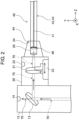
- FIG. 2 is a cross sectional schematic view along line II-II in FIG. 1 .
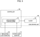
- FIG. 3 is a functional block diagram of lens driving unit 80.
- a direction of laser beam 70 toward partially transmissive mirror 13 in FIG. 2 may be referred to as a Y direction
- a direction of laser beam 70 from partially transmissive mirror 13 toward transmission fiber 40 may be referred to as a Z direction
- a direction perpendicular to the Y direction and the Z direction may be referred to as an X direction.
- the Z direction matches an optical axis direction of laser beam 70 emitted from condenser lens unit 20 within a range of assembly tolerance of an optical system of laser device 100.
- laser device 100 includes laser oscillator 10, condenser lens unit 20, laser beam emission head 30, transmission fiber 40, and controller 50.
- Laser oscillator 10, condenser lens unit 20, and laser beam incident part 44 (see FIG. 2 ) of transmission fiber 40 are housed in housing 60.
- Laser oscillator 10 includes a plurality of laser modules 11, and beam synthesizer 12. Laser oscillator 10 synthesizes laser beams having different wavelengths emitted from the respective plurality of laser modules 11 into one laser beam 70 by beam synthesizer 12. Note that, in the following description, laser oscillator 10 may be referred to as a DDL oscillator. Also, laser module 11 itself is formed of a plurality of laser diodes, and for example, formed of a semiconductor laser array.
- laser beam 70 wavelength-synthesized by beam synthesizer 12 is condensed by condenser lens 21 disposed in condenser lens unit 20, and incident on transmission fiber 40.
- Forming laser oscillator 10 to have such a configuration enables to obtain laser device 100 of high output whose laser beam output exceeds several kW.
- Beam synthesizer 12 also includes therein partially transmissive mirror 13 and output light monitor 14. Partially transmissive mirror 13 is configured to deflect laser beam 70 wavelength-synthesized in beam synthesizer 12 toward condenser lens unit 20 as well as transmits some, for example, 0.1% of laser beam 70.
- Output light monitor 14 is disposed in beam synthesizer 12 to receive laser beam 70 transmitted through partially transmissive mirror 13 and generate a detection signal corresponding to light intensity of laser beam 70 received. A function of output light monitor 14 will be described below. Also, laser oscillator 10 performs laser oscillation by being supplied with electric power from a power source device not shown in the drawings.
- Condenser lens unit 20 includes therein condenser lens 21, slider 22, and reflection light monitor 23.
- Condenser lens 21 condenses laser beam 70 to make a spot diameter smaller than a core diameter of transmission fiber 40 on incident end face 46 of transmission fiber 40.
- Slider 22 keeps condenser lens 21 so as to be freely movable in the Z direction depending on a control signal from controller 50.
- Slider 22 is coupled to a ball screw (not shown) driven by a motor (not shown), for example, and moves in the Z direction with rotation of the ball screw. Note that slider 22 mainly moves in the XY directions during initial position adjustment of the optical system, and moves along the Z direction during shift compensation of a focal position to be described below.
- Reflection light monitor 23 receives laser beam 70 reflected or scattered by laser beam incident part 44 of transmission fiber 40, and generates a detection signal corresponding to light intensity of laser beam 70 received. A function of reflection light monitor 23 will be described below.
- Condenser lens unit 20 also includes connector 24, and laser beam incident part 44 of transmission fiber 40 is connected to connector 24.
- Connector 24 holds quartz block 25 provided in contact with incident end face 46 of transmission fiber 40. Quartz block 25 has a function to protect incident end face 46.
- Transmission fiber 40 is optically coupled with condenser lens 21 of laser oscillator 10, and transmits laser beam 70 received from laser oscillator 10 via condenser lens 21 to laser beam emission head 30.
- Transmission fiber 40 includes core 41 that transmits laser beam 70, cladding 42 provided around core 41 and having a function to enclose laser beam 70 in core 41, and coating 43 covering a surface of cladding 42 (see FIG. 6 ).
- mode stripper 45 (see FIG. 6 ) is provided on laser beam incident part 44 of transmission fiber 40, and details of mode stripper 45 will be described below. Although not illustrated in the drawings, mode stripper 45 is also provided on a laser beam emission part of transmission fiber 40.
- Laser beam emission head 30 emits laser beam 70 transmitted by transmission fiber 40 externally. For example, when this laser device 100 is used for laser processing, laser beam 70 is emitted toward a work (not shown) disposed at a predetermined position.
- Controller 50 controls laser oscillation of laser oscillator 10. Specifically, controller 50 controls laser oscillation by controlling output, on time, and the like with respect to a power source device (not shown) connected to laser oscillator 10. Also, as illustrated in FIG. 3 , controller 50 includes lens movement controller 51. Upon receiving detection signals of reflection light monitor 23 and output light monitor 14, lens movement controller 51 moves slider 22 to make condenser lens 21 come to a predetermined position. Lens movement controller 51 and slider 22 form lens driving unit 80. Note that, when this laser device 100 is used for laser processing, controller 50 may control operation of a manipulator (not shown) to which laser beam emission head 30 is attached.
- laser beams emitted from the plurality of laser modules 11 are synthesized into one laser beam 70 by beam synthesizer 12, and thereafter reflected by partially transmissive mirror 13 provided in beam synthesizer 12 to be introduced to condenser lens 21 in condenser lens unit 20.
- Condenser lens 21 condenses laser beam 70 so as to have a spot diameter smaller than 100 pm on incident end face 46 of transmission fiber 40 in a case where the core diameter of transmission fiber 40 is 100 ⁇ m, for example.
- laser beam 70 condensed When Laser beam 70 condensed is passed through quartz block 25, and incident on core 41 of transmission fiber 40, laser beam 70 propagates in core 41 by total reflection, and is transmitted to the laser beam emission part (not shown) of transmission fiber 40.
- laser beam 70 condensed by condenser lens 21 needs to be precisely incident in core 41 of transmission fiber 40.
- the spot diameter that is a diameter of spot 71 of laser beam 70 needs to be precisely fitted in the core diameter that is a diameter of core 41 of transmission fiber 40.
- FIG. 4A illustrates an incident state of the laser beam on incident end face 46 of transmission fiber 40, and illustrates an ideal state where laser beam 70 fits in core 41.
- FIG. 4B illustrates a state where a center of core 41 and the optical axis of laser beam 70 are misaligned and laser beam 70 is incident so as to be protruded in cladding 42.
- FIG. 4C illustrates a state where the spot diameter of laser beam 70 is larger than the core diameter of transmission fiber 40 and laser beam 70 is incident so as to be protruded in cladding 42.
- a focal position of laser beam 70 substantially matches a center of core 41 of transmission fiber 40, and a diameter of spot 71 of laser beam 70 is equal to or less than the core diameter of transmission fiber 40.
- the focal position of laser beam 70 is misaligned in a surface parallel to incident end face 46 of transmission fiber 40, that is, in an XY plane, so that laser beam 70 is protruded from core 41.
- laser beam 70 is incident on cladding 42, which may disadvantageously lower quality of laser beam 70 as well as damage transmission fiber 40. Accordingly, in this case, by adjusting the focal position of a focal lens by moving condenser lens 21 in the XY plane, laser beam 70 can be fitted in core 41.
- a work for adjusting the position of condenser lens 21 is typically performed at a time when transmission fiber 40 is connected to condenser lens unit 20, and the position of condenser lens unit 21 is fixed when laser oscillation is performed. Also, such a state illustrated in FIG. 4B is typically eliminated by this initial adjustment.
- slider 22 capable of moving in the Z direction while holding condenser lens 21 is provided in condenser lens unit 20. Furthermore, condenser lens 21 is moved by lens driving unit 80 formed of slider 22 and lens movement controller 51 to compensate a focal position shift of laser beam 70.
- FIG. 5 is a schematic view illustrating a function to compensate the focal position shift of laser beam 70 by lens driving unit 80. Alignment of transmission fiber 40 and initial adjustment of the optical system are performed, so that the optical axis of laser beam 70 passed through condenser lens 21 and a center axis of core 41 of transmission fiber 40 match each other within a range of assembly tolerance.
- the focal position of laser beam 70 is adjusted such that the spot diameter of laser beam 70 becomes smaller than the core diameter of transmission fiber 40 on incident end face 46 of transmission fiber 40.
- the focal position of laser beam 70 shifts on a side of condenser lens 21 due to the thermal lens effect, so that the spot diameter of laser beam 70 becomes large than the core diameter of transmission fiber 40. Accordingly, as illustrated in part (c) on a lower side of FIG.
- lens driving unit 80 makes the position of condenser lens 21 come close to the side of transmission fiber 40 in the Z direction to compensate this shift. This adjusts the focal position of laser beam 70 to make the spot diameter of laser beam 70 becomes smaller than the core diameter of transmission fiber 40 again.
- reflection light monitor 23 is provided near laser beam incident part 44 of transmission fiber 40, and lens driving unit 80 determines moving direction of condenser lens 21, that is, whether condenser lens 21 is moved on a side of laser oscillator 10 or a side of transmission fiber 40 in the Z direction is determined, as well as determines a moving amount of condenser lens 21 on the basis of a detection signal of reflection light monitor 23.
- FIG. 6 is a schematic cross-sectional view near laser beam incident part 44 of transmission fiber 40.
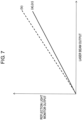
- FIG. 7 is a diagram illustrating a relation between output of laser beam 70 and the detection signal of reflection light monitor 23. Note that (a) to (c) illustrated in FIG. 7 respectively correspond to parts (a) to (c) illustrated in FIG. 5 .
- typical transmission fiber 40 includes mode stripper 45 at each of a vicinity of laser beam incident part 44 and a vicinity of an emission part.
- Mode stripper 45 is a mechanism for removing leak light that does not propagate in core 41 to be incident on cladding 42 among laser beams 70 incident on transmission fiber 40.
- laser beam 70 incident on cladding 42 propagates in cladding 42, so that laser beam 70 of low quality is disadvantageously emitted from the laser beam emission part of transmission fiber 40.
- mode stripper 45 is of converting light incident on cladding 42 into heat without totally reflecting the light for removal, and in this context, some of light incident on cladding 42 is scattered or reflected.
- reflection light monitor 23 is disposed to detect light scattered or reflected by mode stripper 45 in condenser lens unit 20 to which transmission fiber 40 is connected.
- a detection signal corresponding to light intensity detected is generated.
- the detection signal in reflection light monitor 23 is input to lens movement controller 51, and the moving direction and moving amount of slider 22 are calculated by lens movement controller 51.
- a control signal is supplied to slider 22 from lens movement controller 51 on the basis of this calculation result to move slider 22 so that condenser lens 21 comes to a predetermined position.
- lens movement controller 51 need not necessarily be formed by a dedicated electronic circuit or a large - scale integration (LSI), and may be a function block provided by performing software on hardware such as a general-purpose central processing unit (CPU).
- reflection light monitor 23 outputs a signal proportional to laser oscillation output of laser oscillator 10 even when there is no leak light that does not fit in core 41 of transmission fiber 40.
- quartz block 25 is positioned at a connecting portion between condenser lens unit 20 and transmission fiber 40, to inevitably generate reflected light on each boundary surface. Accordingly, to precisely monitor light intensity of leak light in transmission fiber 40, a signal proportional to the laser oscillation output needs to be subtracted.
- a signal proportional to laser oscillation output of laser oscillator 10 can be calculated also from an oscillation command value sent to laser oscillator 10 from controller 50.
- controller 50 for example, when output drop due to aging of laser module 11 or the like occurs, precise monitoring becomes impossible.
- above-mentioned output light monitor 14 is provided in beam synthesizer 12 besides reflection light monitor 23 to calculate an actual output of laser beam 70 on the basis of the detection signal.
- a detection signal corresponding to light intensity detected is generated.
- the detection signal in output light monitor 14 is input to lens movement controller 51 like the detection signal in reflection light monitor 23, and an actual output value of laser beam 70 is calculated by lens movement controller 51 on the basis of the detection signal.
- a value of reflection light monitor 23 output at this actual output value is calculated from the actual output value of laser beam 70 calculated (see FIG.
- FIG. 8 illustrates behaviors of the detection signal of reflection light monitor 23, the detection signal of output light monitor 14, and output of laser beam 70 emitted from transmission fiber 40 with respect to the focal position of laser beam 70 after passed through condenser lens 21. Note that (a) to (c) illustrated in FIG. 8 respectively correspond to parts (a) to (c) illustrated in FIG. 5 .
- the detection signal of reflection light monitor 23 provided on a later stage of condenser lens 21 increases with an increase in scattered light scattered by mode stripper 45 existing in laser beam incident part 44 of transmission fiber 40.
- the detection signal of output light monitor 14 reflects output of laser beam 70 detected by spectroscopy before entered in condenser lens 21 in a previous state of condenser lens 21. Accordingly, the detection signal of output light motor 14 does not depend on the thermal lens effect occurred in condenser lens 21.
- the difference signal obtained based on the detection signal of reflection light monitor 23 and the detection signal by output light monitor 14 is proportional to light intensity of light scattered or reflected by mode stripper 45.
- Moving condenser lens 21 such that the differential signal becomes less than or equal to a predetermined value enables to surely reduce leak light in transmission fiber 40 associated with the shift of the focal position of laser beam 70. This enables to suppress damage of incident end face 46 of transmission fiber 40 and increase optical coupling efficiency between laser oscillator 10 and transmission fiber 40 to suppress lowering of laser beam output.
- the spot shape of laser beam 70 waveform-synthesized by beam synthesizer 12 is hard to be a circle shape and the spot shape can be a shape having a corner.
- leak light protruded from core 41 to be leaked into cladding 42 is emitted to a specific position of mode stripper 45 in a concentrated manner, readily casing local heat generation at this position of mode stripper 45 to readily cause damage of transmission fiber 40.
- the present exemplary embodiment makes it possible to reduce leak light in transmission fiber 40 by adjusting the position of condenser lens 21 to modify the focal position of laser beam 70 also in the above-mentioned case. This enables to suppress damage of transmission fiber 40 and suppress output lowering of laser beam 70.
- the reflection light monitor detects light intensity including light intensity of laser beam reflected or scattered at the laser beam incident part when the laser beam is incident on the laser beam incident part of the transmission fiber, and the lens driving unit adjusts the position of the condenser lens to reduce light intensity detected by the reflection light monitor.
- This configuration makes the reflection light monitor detect light intensity including reflected light or scattered light due to leak light from the transmission fiber, and the position of the condenser lens be adjusted to reduce light intensity detected, making it possible to reduce leak light in the transmission fiber.
- Light intensity detected by the reflection light monitor includes light intensity detected in proportional to output of laser beam emitted from the laser oscillator.
- An output light monitor that detects light intensity of some of laser beam emitted from the laser oscillator is further included, and the lens driving unit calculates light intensity detected in proportional to output of laser beam emitted from the laser oscillator on the basis of light intensity detected by the output light monitor and adjusts the position of the condenser lens in an optical axis direction so as to reduce light intensity obtained by subtracting the light intensity calculated from light intensity detected by the reflection light monitor.
- This configuration enables to surely calculate light intensity of leak light by calculating a component that does not depend on leak light included in light intensity detected by the reflection light monitor using light intensity detected by the output light monitor, making it possible to surely reduce leak light in transmission fiber.
- the lens driving unit preferably adjusts the position of the condenser lens to compensate the shift of the focal position of laser beam due to the thermal lens effect due to temperature rise in the laser device.
- This configuration enables to suppress impact of the thermal lens effect generated in the laser device to reduce leak light in the transmission fiber.
- the laser oscillator preferably includes a plurality of laser modules that emits laser beams having different wavelengths with each other, and a beam synthesizer that wavelength-synthesizes the plurality of laser beams different in wavelength with each other emitted from the plurality of laser modules to emit them as one laser beam.
- This configuration makes it possible to provide a laser device of high output.
- Laser device 100 basically has the same configuration as the configuration illustrated in the first exemplary embodiment, and a mode of movement control of condenser lens 21 during laser oscillation is different.
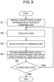
- FIG. 9 illustrates a position adjustment procedure of condenser lens 21 according to the present exemplary embodiment.
- initial adjustment of the optical system such as the position of condenser lens 21 is performed before laser processing.
- laser oscillation is performed by laser oscillator 10 to generate laser beam 70
- condenser lens 21 is moved by lens driving unit 80 to adjust the position of condenser lens 21 to determine an initial position of condenser lens 21 (step S1).
- laser oscillation time is adjusted such that exothermic temperature of condenser lens 21 due to laser beam 70 becomes less than or equal to a predetermined value.
- step S1 as illustrated in FIG.
- the position of condenser lens 21 is adjusted such that the optical axis of laser beam 70 is substantially positioned at a center of core 41 of transmission fiber 40, and the spot diameter of laser beam 70 becomes less than or equal to the core diameter of transmission fiber 40. Laser oscillation is stopped after the initial adjustment.
- step S2 laser oscillation is performed by laser oscillator 10 to generate laser beam 70 (step S2).
- condenser lens 21 when laser oscillation is continued, condenser lens 21 generates heat by absorbing some of laser beam 70, causing the above-mentioned thermal lens effect to change a curvature of condenser lens 21. This shifts the focal position of laser beam 70 such that spot 71 of laser beam 70 is protruded from core 41 as illustrated in FIG. 4B .
- a shift amount of the focal position is calculated on the basis of the detection signal of reflection light monitor 23 and the detection signal of output light monitor 14, and condenser lens 21 is moved in the Z direction by lens driving unit 80, that is, condenser lens 21 is moved along the traveling direction of laser beam 70 such that the shift amount becomes less than or equal to a predetermined value (step S3).
- lens driving unit 80 moves condenser lens 21 to the initial position in step S1 in five seconds (step S4).
- the predetermined time period is predicted on the basis of temperature drop characteristics preliminarily obtained of condenser lens 21 with respect to time.
- step S5 Whether laser oscillation is performed again by laser oscillator 10 is confirmed (step S5), and when laser oscillation is performed, steps S2 to S4 are repeated, and when laser oscillation is not performed, the flow is ended.
- temperature drop time of condenser lens 21 is predicted to adjust the position of condenser lens 21 with the prediction, making it possible to compensate the shift of the focal position of laser beam 70.
- This enables to reduce leak light in transmission fiber 40 through intermittent oscillation period during which thermal expansion and contraction of the condenser lens 21 are repeated.
- This also enables to suppress damage of incident end face 46 of transmission fiber 40 and increase optical coupling efficiency between laser oscillator 10 and transmission fiber 40 to suppress output drop of laser beam 70.
- the lens driving unit moves the condenser lens along the traveling direction of the laser beam from a predetermined position during laser oscillation in an intermittent oscillation period in which the laser oscillator intermittently repeats laser oscillation, and returns the condenser lens to the predetermined position in a predetermined time period after stoppage of laser oscillation to reduce light intensity of the laser beam incident on the cladding through the intermittent oscillation period.
- This configuration enables to stably reduce leak light in the transmission fiber also in a case where thermal expansion and contraction of the condenser lens is repeated due to intermittent laser oscillation.
- the thermal lens effect of condenser lens 21 is described as an example of causing the shift of the focal position of laser beam 70, the shift of the focal position can also occur due to another factor in actuality.
- an incident angle or an incident beam diameter of laser beam 70 to condenser lens 21 may be changed due to, for example, the thermal lens effect due to thermal expansion of another optical component in beam synthesizer 12 and condenser lens unit 20, change of characteristics of laser beam 70 emitted from laser module 11, in particular, the laser diode with respect to temperature, and the like, to fluctuate the focal position of laser beam 70.
- the configurations illustrated in the first and second exemplary embodiments enable to compensate the shift of the focal position of laser beam 70 to reduce leak light in transmission fiber 40.
- the proportional signal may be obtained from an oscillation command value to subtract the proportional signal from the detection signal in reflection light monitor 23 as described above.
- lens movement controller 51 is allowed to generate a control signal to move slider 22 without using the detection signal in output light monitor 14 to adjust the position of condenser lens 21 on the basis of this control signal.
- the laser device according to the present disclosure can reduce leak light in the transmission fiber to suppress laser beam output drop and damage of the transmission fiber, so that it is useful to apply the laser device according to the present disclosure to a laser processing device and the like that each require a laser beam of high output.
Landscapes
- Physics & Mathematics (AREA)
- Optics & Photonics (AREA)
- Engineering & Computer Science (AREA)
- Plasma & Fusion (AREA)
- Mechanical Engineering (AREA)
- Electromagnetism (AREA)
- General Physics & Mathematics (AREA)
- Laser Beam Processing (AREA)
- Optical Couplings Of Light Guides (AREA)
Claims (4)
- Dispositif laser comprenant :un oscillateur laser (10) configuré pour générer un faisceau laser (70) ;une lentille de condenseur (21) configurée pour condenser le faisceau laser (70) émis par l'oscillateur laser (10) ;une fibre de transmission (40) comportant au moins (i) une âme (41) configurée pour transmettre une partie du faisceau laser (70) condensé par la lentille de condenseur (21) et (ii) une gaine (42) prévue autour de l'âme (41) ;un moniteur de lumière de réflexion (23) qui détecte une deuxième intensité lumineuse d'une deuxième partie du faisceau laser lorsque le faisceau laser est incident sur une partie incidente (44) de faisceau laser de la fibre de transmission (40), la deuxième intensité lumineuse comportant une troisième intensité lumineuse d'une troisième partie du faisceau laser réfléchie ou diffusée sur la partie incidente (44) de faisceau laser ;un moniteur de lumière de sortie (14) qui détecte une cinquième intensité lumineuse d'une cinquième partie du faisceau laser émis par l'oscillateur laser (10) ; etune unité d'entraînement de lentille (80) configurée pour régler automatiquement une position de la lentille de condenseur (21) pour réduire une première intensité lumineuse d'une première partie du faisceau laser incident sur la gaine (42), dans lequella deuxième intensité lumineuse détectée par le moniteur de lumière de réflexion (23) comporte une quatrième intensité lumineuse d'une quatrième partie du faisceau laser détectée proportionnellement à la sortie du faisceau laser émis par l'oscillateur laser (10), etl'unité d'entraînement de lentille (80) est configurée pour calculer la quatrième intensité lumineuse détectée proportionnellement à la sortie du faisceau laser émis par l'oscillateur laser (10) sur la base de la cinquième intensité lumineuse détectée par le moniteur de lumière de sortie (14), et pour régler la position de la lentille de condenseur (21) dans une direction d'axe optique de manière à réduire une sixième intensité lumineuse obtenue en soustrayant la quatrième intensité lumineuse calculée de la deuxième intensité lumineuse détectée par le moniteur de lumière de réflexion (23).
- Dispositif laser selon la revendication 1, dans lequel
l'unité d'entraînement de lentille (80) est configurée pour déplacer la lentille de condenseur (21) le long d'une direction de circulation du faisceau laser (70), à partir d'une position prédéterminée pendant l'oscillation laser dans une période d'oscillation intermittente au cours de laquelle l'oscillateur laser (10) répète par intermittence l'oscillation laser, et pour ramener la lentille de condenseur (21) à la position prédéterminée dans une période de temps prédéterminée après l'arrêt de l'oscillation laser, pour réduire la première intensité lumineuse du faisceau laser incident sur la gaine (42) sur la période d'oscillation intermittente. - Dispositif laser selon l'une quelconque des revendications 1 à 2, dans lequel
l'unité d'entraînement de lentille (80) est configurée pour régler la position de la lentille de condenseur (21) pour compenser un décalage d'une position focale du faisceau laser dû à un effet thermique de lentille en raison d'une augmentation de la température dans le dispositif laser. - Dispositif laser selon l'une quelconque des revendications 1 à 3, dans lequell'oscillateur laser (10) comporte une pluralité de modules laser (11) qui émettent des faisceaux laser ayant des longueurs d'onde différentes les unes des autres, etun synthétiseur de faisceau (12) configuré pour synthétiser une pluralité de faisceaux laser ayant des longueurs d'onde différentes les unes des autres, émis par la pluralité de modules laser (11) pour émettre un faisceau laser.
Applications Claiming Priority (2)
| Application Number | Priority Date | Filing Date | Title |
|---|---|---|---|
| JP2017174074 | 2017-09-11 | ||
| PCT/JP2018/032950 WO2019049914A1 (fr) | 2017-09-11 | 2018-09-06 | Dispositif laser |
Publications (3)
| Publication Number | Publication Date |
|---|---|
| EP3683000A1 EP3683000A1 (fr) | 2020-07-22 |
| EP3683000A4 EP3683000A4 (fr) | 2020-11-18 |
| EP3683000B1 true EP3683000B1 (fr) | 2023-05-24 |
Family
ID=65633938
Family Applications (1)
| Application Number | Title | Priority Date | Filing Date |
|---|---|---|---|
| EP18854119.7A Active EP3683000B1 (fr) | 2017-09-11 | 2018-09-06 | Dispositif laser |
Country Status (5)
| Country | Link |
|---|---|
| US (1) | US11329443B2 (fr) |
| EP (1) | EP3683000B1 (fr) |
| JP (1) | JP7411868B2 (fr) |
| CN (1) | CN111050978B (fr) |
| WO (1) | WO2019049914A1 (fr) |
Families Citing this family (4)
| Publication number | Priority date | Publication date | Assignee | Title |
|---|---|---|---|---|
| CN110542025B (zh) * | 2019-09-30 | 2024-03-29 | 浙江光塔安全科技有限公司 | 一种偏光反馈系统 |
| WO2021117850A1 (fr) * | 2019-12-13 | 2021-06-17 | パナソニックIpマネジメント株式会社 | Dispositif laser |
| EP4092473A4 (fr) * | 2020-01-15 | 2023-08-16 | Panasonic Intellectual Property Management Co., Ltd. | Appareil laser et appareil d'usinage laser l'utilisant |
| CN116056829A (zh) * | 2020-07-07 | 2023-05-02 | 松下知识产权经营株式会社 | 用于更改光束形状和强度的阶跃芯光纤结构和方法 |
Family Cites Families (18)
| Publication number | Priority date | Publication date | Assignee | Title |
|---|---|---|---|---|
| JPH0661336B2 (ja) * | 1985-10-31 | 1994-08-17 | 富士写真光機株式会社 | レーザ装置 |
| JPS62102750U (fr) * | 1985-12-19 | 1987-06-30 | ||
| GB9106874D0 (en) * | 1991-04-02 | 1991-05-22 | Lumonics Ltd | Optical fibre assembly for a laser system |
| JP3645013B2 (ja) * | 1994-10-14 | 2005-05-11 | 三菱電機株式会社 | 光伝送装置、固体レーザ装置、及びこれらを用いたレーザ加工装置 |
| JPH11264921A (ja) * | 1998-03-16 | 1999-09-28 | Kawasaki Heavy Ind Ltd | レーザ光のファイバ導光方法およびレーザ導光ファイバ装置 |
| JP2001343558A (ja) * | 2000-06-02 | 2001-12-14 | Mitsubishi Electric Corp | 高エネルギー光伝送装置 |
| JP2004151297A (ja) | 2002-10-30 | 2004-05-27 | Pentax Corp | 位置検出システムおよび位置決め方法 |
| US20040114935A1 (en) * | 2002-11-05 | 2004-06-17 | Pentax Corporation | Optical communication device |
| US7146073B2 (en) * | 2004-07-19 | 2006-12-05 | Quantronix Corporation | Fiber delivery system with enhanced passive fiber protection and active monitoring |
| JP2006349815A (ja) * | 2005-06-14 | 2006-12-28 | Pentax Corp | 光通信装置 |
| JP4690967B2 (ja) | 2006-08-21 | 2011-06-01 | 新日本製鐵株式会社 | 加工深さを増加したレーザ加工装置 |
| JP2008170636A (ja) * | 2007-01-10 | 2008-07-24 | Nec Electronics Corp | 半導体レーザモジュール |
| JP5705503B2 (ja) * | 2010-10-28 | 2015-04-22 | 三菱重工業株式会社 | レーザ加工装置及びレーザビーム調整方法 |
| JP5908705B2 (ja) * | 2011-11-30 | 2016-04-26 | 株式会社ディスコ | レーザー加工装置 |
| JP2016112609A (ja) * | 2014-12-18 | 2016-06-23 | パナソニックIpマネジメント株式会社 | レーザ切断装置およびレーザ切断方法 |
| JP2016181643A (ja) | 2015-03-25 | 2016-10-13 | 株式会社アマダホールディングス | 半導体レーザ発振器 |
| US11052482B2 (en) * | 2016-02-12 | 2021-07-06 | Ipg Photonics Corporation | Laser alignment apparatus and system for alignment of output fiber of a fiber laser |
| CN205967800U (zh) * | 2016-08-08 | 2017-02-22 | 江苏启澜激光科技有限公司 | 一种激光束输出光头动态控制装置 |
-
2018
- 2018-09-06 EP EP18854119.7A patent/EP3683000B1/fr active Active
- 2018-09-06 JP JP2019540988A patent/JP7411868B2/ja active Active
- 2018-09-06 WO PCT/JP2018/032950 patent/WO2019049914A1/fr not_active Ceased
- 2018-09-06 CN CN201880057726.5A patent/CN111050978B/zh active Active
-
2020
- 2020-03-04 US US16/808,441 patent/US11329443B2/en active Active
Also Published As
| Publication number | Publication date |
|---|---|
| EP3683000A1 (fr) | 2020-07-22 |
| US11329443B2 (en) | 2022-05-10 |
| CN111050978A (zh) | 2020-04-21 |
| EP3683000A4 (fr) | 2020-11-18 |
| JP7411868B2 (ja) | 2024-01-12 |
| US20200203910A1 (en) | 2020-06-25 |
| WO2019049914A1 (fr) | 2019-03-14 |
| JPWO2019049914A1 (ja) | 2020-10-15 |
| CN111050978B (zh) | 2022-05-17 |
Similar Documents
| Publication | Publication Date | Title |
|---|---|---|
| US11329443B2 (en) | Laser device | |
| JP6136315B2 (ja) | 光送信モジュールの製造方法 | |
| JP6373714B2 (ja) | ダイレクトダイオードレーザ加工装置及びその出力監視方法 | |
| JP6340902B2 (ja) | 光モジュールの製造方法 | |
| WO2016152404A1 (fr) | Oscillateur laser à semi-conducteur | |
| US10788368B1 (en) | Thermal isolation structure | |
| JP7142312B2 (ja) | レーザ加工装置及びレーザ発振制御方法 | |
| US11841278B2 (en) | Temperature measurement sensor, temperature measurement system, and temperature measurement method | |
| US9470854B2 (en) | Method for assembling optical module and optical module | |
| US11607746B2 (en) | Laser device and laser processing device using same | |
| US20170250755A1 (en) | Semiconductor device | |
| JP2006045598A (ja) | 配管の残留応力改善装置 | |
| JP7038323B2 (ja) | レーザ発振器及びそれを用いたレーザ加工装置、レーザ発振器の点検方法 | |
| EP4074454B1 (fr) | Dispositif laser et procédé de commande de dispositif laser | |
| EP1947506B1 (fr) | Procede de mise en veille d´une source de lumiere laser | |
| JP5153432B2 (ja) | 波長ロッカモジュール | |
| JP6132426B2 (ja) | レーザー装置 | |
| JP2020060725A (ja) | レーザ発振器及びそれを用いたレーザ加工装置 | |
| JP2018190905A (ja) | レーザ装置 | |
| EP4092473A1 (fr) | Appareil laser et appareil d'usinage laser l'utilisant | |
| JP2025007313A (ja) | レーザ発振器及びこれを備えたレーザ加工装置 | |
| JP5870059B2 (ja) | 距離測定装置及び距離測定方法 | |
| US8292686B2 (en) | Method and apparatus for manufacturing light source | |
| HK1118614A (en) | Method for having laser light source in standby status | |
| KR20140035015A (ko) | 레이저 가공장치 |
Legal Events
| Date | Code | Title | Description |
|---|---|---|---|
| STAA | Information on the status of an ep patent application or granted ep patent |
Free format text: STATUS: THE INTERNATIONAL PUBLICATION HAS BEEN MADE |
|
| PUAI | Public reference made under article 153(3) epc to a published international application that has entered the european phase |
Free format text: ORIGINAL CODE: 0009012 |
|
| STAA | Information on the status of an ep patent application or granted ep patent |
Free format text: STATUS: REQUEST FOR EXAMINATION WAS MADE |
|
| 17P | Request for examination filed |
Effective date: 20200311 |
|
| AK | Designated contracting states |
Kind code of ref document: A1 Designated state(s): AL AT BE BG CH CY CZ DE DK EE ES FI FR GB GR HR HU IE IS IT LI LT LU LV MC MK MT NL NO PL PT RO RS SE SI SK SM TR |
|
| AX | Request for extension of the european patent |
Extension state: BA ME |
|
| A4 | Supplementary search report drawn up and despatched |
Effective date: 20201020 |
|
| RIC1 | Information provided on ipc code assigned before grant |
Ipc: B23K 26/064 20140101ALI20201014BHEP Ipc: B23K 26/00 20140101AFI20201014BHEP Ipc: G02B 6/42 20060101ALI20201014BHEP |
|
| DAV | Request for validation of the european patent (deleted) | ||
| DAX | Request for extension of the european patent (deleted) | ||
| GRAP | Despatch of communication of intention to grant a patent |
Free format text: ORIGINAL CODE: EPIDOSNIGR1 |
|
| STAA | Information on the status of an ep patent application or granted ep patent |
Free format text: STATUS: GRANT OF PATENT IS INTENDED |
|
| INTG | Intention to grant announced |
Effective date: 20230208 |
|
| GRAS | Grant fee paid |
Free format text: ORIGINAL CODE: EPIDOSNIGR3 |
|
| GRAA | (expected) grant |
Free format text: ORIGINAL CODE: 0009210 |
|
| STAA | Information on the status of an ep patent application or granted ep patent |
Free format text: STATUS: THE PATENT HAS BEEN GRANTED |
|
| AK | Designated contracting states |
Kind code of ref document: B1 Designated state(s): AL AT BE BG CH CY CZ DE DK EE ES FI FR GB GR HR HU IE IS IT LI LT LU LV MC MK MT NL NO PL PT RO RS SE SI SK SM TR |
|
| REG | Reference to a national code |
Ref country code: GB Ref legal event code: FG4D |
|
| REG | Reference to a national code |
Ref country code: CH Ref legal event code: EP |
|
| REG | Reference to a national code |
Ref country code: DE Ref legal event code: R096 Ref document number: 602018050308 Country of ref document: DE |
|
| REG | Reference to a national code |
Ref country code: AT Ref legal event code: REF Ref document number: 1569224 Country of ref document: AT Kind code of ref document: T Effective date: 20230615 |
|
| REG | Reference to a national code |
Ref country code: IE Ref legal event code: FG4D |
|
| REG | Reference to a national code |
Ref country code: LT Ref legal event code: MG9D |
|
| REG | Reference to a national code |
Ref country code: NL Ref legal event code: MP Effective date: 20230524 |
|
| REG | Reference to a national code |
Ref country code: AT Ref legal event code: MK05 Ref document number: 1569224 Country of ref document: AT Kind code of ref document: T Effective date: 20230524 |
|
| PG25 | Lapsed in a contracting state [announced via postgrant information from national office to epo] |
Ref country code: SE Free format text: LAPSE BECAUSE OF FAILURE TO SUBMIT A TRANSLATION OF THE DESCRIPTION OR TO PAY THE FEE WITHIN THE PRESCRIBED TIME-LIMIT Effective date: 20230524 Ref country code: PT Free format text: LAPSE BECAUSE OF FAILURE TO SUBMIT A TRANSLATION OF THE DESCRIPTION OR TO PAY THE FEE WITHIN THE PRESCRIBED TIME-LIMIT Effective date: 20230925 Ref country code: NO Free format text: LAPSE BECAUSE OF FAILURE TO SUBMIT A TRANSLATION OF THE DESCRIPTION OR TO PAY THE FEE WITHIN THE PRESCRIBED TIME-LIMIT Effective date: 20230824 Ref country code: NL Free format text: LAPSE BECAUSE OF FAILURE TO SUBMIT A TRANSLATION OF THE DESCRIPTION OR TO PAY THE FEE WITHIN THE PRESCRIBED TIME-LIMIT Effective date: 20230524 Ref country code: ES Free format text: LAPSE BECAUSE OF FAILURE TO SUBMIT A TRANSLATION OF THE DESCRIPTION OR TO PAY THE FEE WITHIN THE PRESCRIBED TIME-LIMIT Effective date: 20230524 Ref country code: AT Free format text: LAPSE BECAUSE OF FAILURE TO SUBMIT A TRANSLATION OF THE DESCRIPTION OR TO PAY THE FEE WITHIN THE PRESCRIBED TIME-LIMIT Effective date: 20230524 |
|
| PG25 | Lapsed in a contracting state [announced via postgrant information from national office to epo] |
Ref country code: RS Free format text: LAPSE BECAUSE OF FAILURE TO SUBMIT A TRANSLATION OF THE DESCRIPTION OR TO PAY THE FEE WITHIN THE PRESCRIBED TIME-LIMIT Effective date: 20230524 Ref country code: PL Free format text: LAPSE BECAUSE OF FAILURE TO SUBMIT A TRANSLATION OF THE DESCRIPTION OR TO PAY THE FEE WITHIN THE PRESCRIBED TIME-LIMIT Effective date: 20230524 Ref country code: LV Free format text: LAPSE BECAUSE OF FAILURE TO SUBMIT A TRANSLATION OF THE DESCRIPTION OR TO PAY THE FEE WITHIN THE PRESCRIBED TIME-LIMIT Effective date: 20230524 Ref country code: LT Free format text: LAPSE BECAUSE OF FAILURE TO SUBMIT A TRANSLATION OF THE DESCRIPTION OR TO PAY THE FEE WITHIN THE PRESCRIBED TIME-LIMIT Effective date: 20230524 Ref country code: IS Free format text: LAPSE BECAUSE OF FAILURE TO SUBMIT A TRANSLATION OF THE DESCRIPTION OR TO PAY THE FEE WITHIN THE PRESCRIBED TIME-LIMIT Effective date: 20230924 Ref country code: HR Free format text: LAPSE BECAUSE OF FAILURE TO SUBMIT A TRANSLATION OF THE DESCRIPTION OR TO PAY THE FEE WITHIN THE PRESCRIBED TIME-LIMIT Effective date: 20230524 Ref country code: GR Free format text: LAPSE BECAUSE OF FAILURE TO SUBMIT A TRANSLATION OF THE DESCRIPTION OR TO PAY THE FEE WITHIN THE PRESCRIBED TIME-LIMIT Effective date: 20230825 |
|
| PG25 | Lapsed in a contracting state [announced via postgrant information from national office to epo] |
Ref country code: FI Free format text: LAPSE BECAUSE OF FAILURE TO SUBMIT A TRANSLATION OF THE DESCRIPTION OR TO PAY THE FEE WITHIN THE PRESCRIBED TIME-LIMIT Effective date: 20230524 |
|
| PG25 | Lapsed in a contracting state [announced via postgrant information from national office to epo] |
Ref country code: SK Free format text: LAPSE BECAUSE OF FAILURE TO SUBMIT A TRANSLATION OF THE DESCRIPTION OR TO PAY THE FEE WITHIN THE PRESCRIBED TIME-LIMIT Effective date: 20230524 |
|
| PG25 | Lapsed in a contracting state [announced via postgrant information from national office to epo] |
Ref country code: SM Free format text: LAPSE BECAUSE OF FAILURE TO SUBMIT A TRANSLATION OF THE DESCRIPTION OR TO PAY THE FEE WITHIN THE PRESCRIBED TIME-LIMIT Effective date: 20230524 Ref country code: SK Free format text: LAPSE BECAUSE OF FAILURE TO SUBMIT A TRANSLATION OF THE DESCRIPTION OR TO PAY THE FEE WITHIN THE PRESCRIBED TIME-LIMIT Effective date: 20230524 Ref country code: RO Free format text: LAPSE BECAUSE OF FAILURE TO SUBMIT A TRANSLATION OF THE DESCRIPTION OR TO PAY THE FEE WITHIN THE PRESCRIBED TIME-LIMIT Effective date: 20230524 Ref country code: EE Free format text: LAPSE BECAUSE OF FAILURE TO SUBMIT A TRANSLATION OF THE DESCRIPTION OR TO PAY THE FEE WITHIN THE PRESCRIBED TIME-LIMIT Effective date: 20230524 Ref country code: DK Free format text: LAPSE BECAUSE OF FAILURE TO SUBMIT A TRANSLATION OF THE DESCRIPTION OR TO PAY THE FEE WITHIN THE PRESCRIBED TIME-LIMIT Effective date: 20230524 Ref country code: CZ Free format text: LAPSE BECAUSE OF FAILURE TO SUBMIT A TRANSLATION OF THE DESCRIPTION OR TO PAY THE FEE WITHIN THE PRESCRIBED TIME-LIMIT Effective date: 20230524 |
|
| REG | Reference to a national code |
Ref country code: DE Ref legal event code: R097 Ref document number: 602018050308 Country of ref document: DE |
|
| PLBE | No opposition filed within time limit |
Free format text: ORIGINAL CODE: 0009261 |
|
| STAA | Information on the status of an ep patent application or granted ep patent |
Free format text: STATUS: NO OPPOSITION FILED WITHIN TIME LIMIT |
|
| REG | Reference to a national code |
Ref country code: CH Ref legal event code: PL |
|
| 26N | No opposition filed |
Effective date: 20240227 |
|
| PG25 | Lapsed in a contracting state [announced via postgrant information from national office to epo] |
Ref country code: SI Free format text: LAPSE BECAUSE OF FAILURE TO SUBMIT A TRANSLATION OF THE DESCRIPTION OR TO PAY THE FEE WITHIN THE PRESCRIBED TIME-LIMIT Effective date: 20230524 |
|
| PG25 | Lapsed in a contracting state [announced via postgrant information from national office to epo] |
Ref country code: LU Free format text: LAPSE BECAUSE OF NON-PAYMENT OF DUE FEES Effective date: 20230906 |
|
| REG | Reference to a national code |
Ref country code: BE Ref legal event code: MM Effective date: 20230930 |
|
| GBPC | Gb: european patent ceased through non-payment of renewal fee |
Effective date: 20230906 |
|
| PG25 | Lapsed in a contracting state [announced via postgrant information from national office to epo] |
Ref country code: MC Free format text: LAPSE BECAUSE OF FAILURE TO SUBMIT A TRANSLATION OF THE DESCRIPTION OR TO PAY THE FEE WITHIN THE PRESCRIBED TIME-LIMIT Effective date: 20230524 Ref country code: SI Free format text: LAPSE BECAUSE OF FAILURE TO SUBMIT A TRANSLATION OF THE DESCRIPTION OR TO PAY THE FEE WITHIN THE PRESCRIBED TIME-LIMIT Effective date: 20230524 Ref country code: LU Free format text: LAPSE BECAUSE OF NON-PAYMENT OF DUE FEES Effective date: 20230906 Ref country code: IT Free format text: LAPSE BECAUSE OF FAILURE TO SUBMIT A TRANSLATION OF THE DESCRIPTION OR TO PAY THE FEE WITHIN THE PRESCRIBED TIME-LIMIT Effective date: 20230524 |
|
| REG | Reference to a national code |
Ref country code: IE Ref legal event code: MM4A |
|
| PG25 | Lapsed in a contracting state [announced via postgrant information from national office to epo] |
Ref country code: IE Free format text: LAPSE BECAUSE OF NON-PAYMENT OF DUE FEES Effective date: 20230906 |
|
| PG25 | Lapsed in a contracting state [announced via postgrant information from national office to epo] |
Ref country code: GB Free format text: LAPSE BECAUSE OF NON-PAYMENT OF DUE FEES Effective date: 20230906 |
|
| PG25 | Lapsed in a contracting state [announced via postgrant information from national office to epo] |
Ref country code: CH Free format text: LAPSE BECAUSE OF NON-PAYMENT OF DUE FEES Effective date: 20230930 |
|
| PG25 | Lapsed in a contracting state [announced via postgrant information from national office to epo] |
Ref country code: IE Free format text: LAPSE BECAUSE OF NON-PAYMENT OF DUE FEES Effective date: 20230906 Ref country code: GB Free format text: LAPSE BECAUSE OF NON-PAYMENT OF DUE FEES Effective date: 20230906 Ref country code: FR Free format text: LAPSE BECAUSE OF NON-PAYMENT OF DUE FEES Effective date: 20230930 Ref country code: CH Free format text: LAPSE BECAUSE OF NON-PAYMENT OF DUE FEES Effective date: 20230930 |
|
| PG25 | Lapsed in a contracting state [announced via postgrant information from national office to epo] |
Ref country code: BE Free format text: LAPSE BECAUSE OF NON-PAYMENT OF DUE FEES Effective date: 20230930 |
|
| PG25 | Lapsed in a contracting state [announced via postgrant information from national office to epo] |
Ref country code: BG Free format text: LAPSE BECAUSE OF FAILURE TO SUBMIT A TRANSLATION OF THE DESCRIPTION OR TO PAY THE FEE WITHIN THE PRESCRIBED TIME-LIMIT Effective date: 20230524 |
|
| PG25 | Lapsed in a contracting state [announced via postgrant information from national office to epo] |
Ref country code: BG Free format text: LAPSE BECAUSE OF FAILURE TO SUBMIT A TRANSLATION OF THE DESCRIPTION OR TO PAY THE FEE WITHIN THE PRESCRIBED TIME-LIMIT Effective date: 20230524 |
|
| PG25 | Lapsed in a contracting state [announced via postgrant information from national office to epo] |
Ref country code: CY Free format text: LAPSE BECAUSE OF FAILURE TO SUBMIT A TRANSLATION OF THE DESCRIPTION OR TO PAY THE FEE WITHIN THE PRESCRIBED TIME-LIMIT; INVALID AB INITIO Effective date: 20180906 |
|
| PG25 | Lapsed in a contracting state [announced via postgrant information from national office to epo] |
Ref country code: HU Free format text: LAPSE BECAUSE OF FAILURE TO SUBMIT A TRANSLATION OF THE DESCRIPTION OR TO PAY THE FEE WITHIN THE PRESCRIBED TIME-LIMIT; INVALID AB INITIO Effective date: 20180906 |
|
| PGFP | Annual fee paid to national office [announced via postgrant information from national office to epo] |
Ref country code: DE Payment date: 20250919 Year of fee payment: 8 |
|
| PG25 | Lapsed in a contracting state [announced via postgrant information from national office to epo] |
Ref country code: TR Free format text: LAPSE BECAUSE OF FAILURE TO SUBMIT A TRANSLATION OF THE DESCRIPTION OR TO PAY THE FEE WITHIN THE PRESCRIBED TIME-LIMIT Effective date: 20230524 |