EP3681836B1 - Dispositif d'installation pour une utlisation dans une cage d'ascenseur - Google Patents
Dispositif d'installation pour une utlisation dans une cage d'ascenseur Download PDFInfo
- Publication number
- EP3681836B1 EP3681836B1 EP18762878.9A EP18762878A EP3681836B1 EP 3681836 B1 EP3681836 B1 EP 3681836B1 EP 18762878 A EP18762878 A EP 18762878A EP 3681836 B1 EP3681836 B1 EP 3681836B1
- Authority
- EP
- European Patent Office
- Prior art keywords
- installation
- carrier
- displacement device
- elevator shaft
- displacement
- Prior art date
- Legal status (The legal status is an assumption and is not a legal conclusion. Google has not performed a legal analysis and makes no representation as to the accuracy of the status listed.)
- Active
Links
- 238000009434 installation Methods 0.000 title claims description 184
- 238000006073 displacement reaction Methods 0.000 claims description 106
- 239000000969 carrier Substances 0.000 claims description 23
- 239000000725 suspension Substances 0.000 claims description 18
- 239000000463 material Substances 0.000 claims description 5
- 238000000034 method Methods 0.000 description 7
- 239000002184 metal Substances 0.000 description 5
- 238000005452 bending Methods 0.000 description 4
- 241001669679 Eleotris Species 0.000 description 2
- OKTJSMMVPCPJKN-UHFFFAOYSA-N Carbon Chemical compound [C] OKTJSMMVPCPJKN-UHFFFAOYSA-N 0.000 description 1
- 229910052799 carbon Inorganic materials 0.000 description 1
- 238000007654 immersion Methods 0.000 description 1
- 230000003993 interaction Effects 0.000 description 1
- 239000002990 reinforced plastic Substances 0.000 description 1
Images

Classifications
-
- B—PERFORMING OPERATIONS; TRANSPORTING
- B66—HOISTING; LIFTING; HAULING
- B66B—ELEVATORS; ESCALATORS OR MOVING WALKWAYS
- B66B19/00—Mining-hoist operation
-
- B—PERFORMING OPERATIONS; TRANSPORTING
- B66—HOISTING; LIFTING; HAULING
- B66B—ELEVATORS; ESCALATORS OR MOVING WALKWAYS
- B66B7/00—Other common features of elevators
- B66B7/02—Guideways; Guides
- B66B7/023—Mounting means therefor
-
- B—PERFORMING OPERATIONS; TRANSPORTING
- B66—HOISTING; LIFTING; HAULING
- B66B—ELEVATORS; ESCALATORS OR MOVING WALKWAYS
- B66B9/00—Kinds or types of lifts in, or associated with, buildings or other structures
- B66B9/16—Mobile or transportable lifts specially adapted to be shifted from one part of a building or other structure to another part or to another building or structure
- B66B9/187—Mobile or transportable lifts specially adapted to be shifted from one part of a building or other structure to another part or to another building or structure with a liftway specially adapted for temporary connection to a building or other structure
-
- E—FIXED CONSTRUCTIONS
- E04—BUILDING
- E04G—SCAFFOLDING; FORMS; SHUTTERING; BUILDING IMPLEMENTS OR AIDS, OR THEIR USE; HANDLING BUILDING MATERIALS ON THE SITE; REPAIRING, BREAKING-UP OR OTHER WORK ON EXISTING BUILDINGS
- E04G21/00—Preparing, conveying, or working-up building materials or building elements in situ; Other devices or measures for constructional work
- E04G21/14—Conveying or assembling building elements
Definitions
- the invention relates to an installation device for use in an elevator shaft according to the preamble of claim 1.
- the US 8,646,224 B2 describes an installation device for use in an elevator shaft which has a beam with a first and a second beam end. At the first end of the girder, a support element is pivotably arranged, by means of which the girder can be supported in an installation position of the installation device on a threshold of a door opening of the elevator shaft. In the installation position of the installation device, the carrier is supported via the second carrier end on a shaft wall opposite the named door opening of the elevator shaft. The length of the girder is greater than the distance between the shaft wall and the threshold of the door opening, so that in the installation position the girder is inclined in the elevator shaft with respect to the horizontal.
- the installation device has openings to which a displacement device, for example in the form of an electric winch, can be attached via a rope. The displacement device thus always hangs below the girder and thus below the named openings down into the elevator shaft.
- the EP 2636629 A1 and the JP 2011225336 A also describe installation devices for use in an elevator shaft.
- the installation device In order to bring the installation device into the installation position, it is pulled upwards within the elevator shaft by a displacement device fixed above the door opening, for example in a shaft head of the elevator shaft, until the support element can be fixed on the threshold of the door opening, for example with screws.
- the installation device can then be pivoted in the direction of the shaft wall opposite the door opening until it can be supported on the shaft wall and has thus reached the installation position.
- Displacement device When pulling up the installation device there is still none Displacement device arranged on the installation device.
- the displacement device is only attached to the installation device after it has been fixed to the threshold of the door opening, so that this work has to take place inside the elevator shaft.
- the displacement device can again be used with which the installation device is pulled up in the elevator shaft.
- the installation device according to the invention for use in an elevator shaft has a first carrier which has a first carrier end and a second carrier end, a support element which is pivotably arranged on the first carrier end and a receiving device for receiving a displacement device by means of which installation material is moved in the elevator shaft can.
- the support element is designed and arranged such that the first carrier can be supported in an installation position of the installation device via the support element in the area of a door opening, in particular on a threshold of a door opening of the elevator shaft.
- the second support end is designed such that the first support in the installation position of the installation device can at least indirectly support itself via the second support end on a shaft wall opposite the named door opening of the elevator shaft.
- the receiving device for receiving the displacement device is designed and arranged in the installation position of the installation device on an upper side of the installation device that a displacement device received by the receiving device is supported from above on the receiving device in the installation position of the installation device.
- the receiving device is arranged in particular in the area of the first carrier end.
- the installation device has a deflection roller which is designed and arranged in such a way that it can deflect a support means of a displacement device received by the receiving device.
- the position of the suspension element in the elevator shaft is thus determined by the position of the pulley.
- the position of the displacement device can thus be selected largely independently of a position of the suspension element in the elevator shaft.
- the displacement device can thus be arranged in the region of the first end of the support without the support means also running directly along a shaft wall of the elevator shaft.
- the deflection roller In the installation position of the installation device, the deflection roller is arranged in particular approximately in the middle of the elevator shaft. The deflection thus takes place in particular in such a way that the suspension element is deflected vertically downwards approximately in the middle of the elevator shaft.
- the design and arrangement of the receiving device according to the invention makes it possible, in the installation position of the installation device, to arrange the displacement device from above on the receiving device from the floor associated with the door opening.
- the displacement device can in particular first be placed on the receiving device in the region of the first end of the carrier and then pushed over the receiving device and, if necessary, the first carrier to their correct position.
- the displacing device can thus be arranged from the floor and thus from outside the elevator shaft. It is therefore not necessary for a fitter to go into the elevator shaft for this, which is always associated with a certain risk.
- no further displacement device has to be provided in the elevator shaft by means of which the displacement device provided for the installation device can be displaced in the elevator shaft.
- the displacement device provided for the installation device is designed in particular as an electric winch that can be controlled by a control device.
- the displacement device interacts with a suspension element, which can be designed, for example, as a rope, a belt or a chain.
- a suspension element which can be designed, for example, as a rope, a belt or a chain.
- the suspension element runs downwards from the displacement device in the elevator shaft.
- the displacement device is not a necessary, but only an optional component of the installation device according to the invention.
- the installation device can in particular be used during the installation of an elevator system in an elevator shaft. It can be used particularly advantageously if the elevator system does not have a machine room arranged above the elevator shaft or the elevator shaft is so high that an installation device has to be arranged at different heights during the installation of the elevator system.
- a displacement device arranged on the installation device installation material which is required during installation can be displaced in the elevator shaft.
- the installation material can, for example, be guide rails that are fixed to the shaft walls and serve to guide an elevator car. It is also possible for a work platform on which fitters can carry out installation work to be relocated by the relocation device in the elevator shaft.
- the installation device according to the invention is used to relocate an automated assembly device for performing installations in an elevator shaft, such as those in FIG WO 2017/016783 A1 is described.
- the first carrier is designed as an element elongated in a direction of extent of the installation device and consists in particular of metal. It is also possible that the first carrier consists of a different material, for example a reinforced plastic or carbon.
- the first carrier can for example be constructed mainly from a T-carrier, a double-T-carrier or a pipe.
- the support element is arranged pivotably on the first carrier end of the first carrier, the associated pivot axis in particular running perpendicular to the direction of extension of the first carrier and horizontally in the installation position of the installation device.
- the support element has in particular two contact elements that form a right angle.
- the contact elements are designed and arranged so that in the installation position of the installation device a contact element on a Bottom of a threshold of a door opening and the other rests against the shaft wall adjacent to the threshold.
- the contact elements have in particular through holes through which they and thus the support element can be screwed to the floor or the shaft wall.
- the first carrier can be pivoted about the named pivot axis into the elevator shaft.
- the support element has only one contact element, by means of which the support element can be fixed to the bottom of the threshold of a door opening and the other to the shaft wall adjoining the threshold and thus in the area of the door opening.
- the installation position of the installation device is to be understood here as the position of the installation device in which it can be used for installing an elevator system in the elevator shaft.
- the first carrier is supported on the threshold of a door opening of the elevator shaft via the first support element, the support element being fixed on the threshold in particular as described above.
- the first carrier is supported at least indirectly via the second carrier end on a shaft wall opposite the named door opening of the elevator shaft.
- An indirect support should be understood to mean that a further support element is arranged on the second support end, via which the second support end is supported on the shaft wall. It is also possible for the second end of the beam to be supported directly on the shaft wall.
- the support of the second end of the girder takes place in particular at a height above the threshold mentioned, so that the first girder is arranged inclined upwards, starting from the threshold.
- the shaft wall opposite the door opening can also have a shoulder on which the first carrier can rest.
- the first carrier can also be arranged horizontally or inclined downwards.
- the receiving device for receiving the displacement device forms in particular a mainly flat surface on which at least part of the displacement device stands in the installation position of the installation device and this part is thus supported from above on the receiving device. You can use it as a be designed as a separate component that is connected to the carrier.
- the receiving device can also be designed in one piece with the carrier, that is to say as an integral component of the carrier.
- the receiving device for receiving the displacement device has at least one first alignment element which is designed and arranged such that it interacts with a second alignment element of the displacement device in a correct mounting position of the displacement device with respect to the receiving device. This can advantageously ensure that the displacement device is arranged in the correct assembly position on the receiving device.
- the first alignment element is designed in particular as a recess or opening into which the second alignment element, designed as an extension, dips when the displacement device is correctly positioned with respect to the receiving device.
- the extension can be designed, for example, as a pin or can be formed by bending over part of a floor panel of the displacement device or a mounting plate arranged on the displacement device. Said mounting plate is screwed onto the displacement device at the bottom, for example, and can be made in one or more parts. If the said mounting plate is connected to the displacement device, that is to say screwed, for example, it can be regarded as part of the displacement device.
- first alignment element is designed as an extension and the second alignment element is designed as a recess.
- the installation device has a displacement device received by the receiving device.
- the displacement device thus forms part of the installation device.
- the displacement device has at least one guide element which is designed and arranged such that it interacts with a guide of the installation device when the displacement device is arranged on the receiving device.
- the displacement device can thus be securely arranged on the receiving device, ie without the risk of the displacement device sliding down from the installation device and, in the worst case, falling into the elevator shaft.
- the displacement device can be brought into the correct position with respect to the receiving device in a particularly simple manner.
- the guide element can be designed, for example, as an extension and the guide as a recess or opening.
- the extension can be designed, for example, as a pin or can be formed by bending over part of a floor panel of the displacement device or a mounting plate arranged on the displacement device.
- the aforementioned mounting plate can thus in particular have the aforementioned second alignment element and the guide element.
- the guide element is designed as a recess and the guide as an extension.
- the displacement device is in particular first placed on the receiving device or the carrier and then shifted relative to the receiving device until it has reached the correct position relative to the receiving device.
- the interaction of the guide element and the guide takes place in particular during the displacement of the displacement device.
- the installation device has a second carrier which is arranged at a distance parallel to the first carrier and the two carriers form the mentioned guide of the installation device.
- the guide can thus be designed to be particularly simple and inexpensive.
- the guide element cooperating with the guide is then designed in particular as an extension which, during the arrangement of the displacement device, dips into the space between the two carriers and slides along the two carriers.
- the second carrier is designed in particular to be identical to the first carrier.
- the Both carriers are firmly connected to one another, in particular by the receiving device and the other components of the installation device.
- the receiving device and the further components are firmly connected to both the first and the second carrier, for example screwed or clamped.
- the first and the second carrier it is also possible for the first and the second carrier to be formed by a single component.
- the displacement device has at least one sliding element which is designed and arranged such that it slides along the receiving device and / or the first carrier when the displacement device is arranged on the receiving device. This enables a particularly simple displacement and thus a particularly simple arrangement of the displacement device on the receiving device.
- the sliding element can slide first on the receiving device and then on the first and - if present - on the second carrier. It is also possible for the sliding element to slide only on the receiving device or only on the carrier or carriers. It is not necessary for the sliding element to slide on the receiving device during the entire arrangement of the displacement device.
- the sliding element has, in particular, a planar sliding surface which is rounded on one edge.
- the edge with the rounding is arranged in such a way that it is arranged at the front when the displacement device is pushed on in the direction of the second carrier end and the rounding is designed so that it is directed away from the receiving device or the carrier.
- the sliding element can be a component or part of the displacement device or the mounting plate mentioned.
- a region of the displacement device that is oriented in the direction of the second carrier end of the first carrier is braced to the first and / or second carrier with a tensioning belt.
- a turnbuckle of the tensioning belt is arranged in particular on the top or on the side of the displacement device.
- the tensioning belt can be pulled from the floor assigned to the door opening and thus the displacement device can be tensioned. Fixing the The displacement device can thus be carried out particularly safely and easily. Fixing the displacement device on the receiving device with screws in the area oriented in the direction of the second carrier end of the first carrier would be much more complex and also more dangerous, since these would have to be arranged on the underside of the displacement device.
- the said tensioning belt is thus arranged on a region of the displacement device that protrudes into the elevator shaft.
- it can be laid loosely around the displacement device and the carrier or carriers even before the displacement device is arranged or pushed on.
- the displacement device can additionally also be screwed to the first and / or second carrier in the area of the first and / or second carrier end. This area is easily and safely accessible from the floor assigned to the door opening.
- the installation device can be brought into the installation position from the floor assigned to the door opening. All procedural steps can be carried out from the floor mentioned without a fitter having to go into the shaft. In addition, it is not necessary to provide a further displacement device in the elevator shaft. The installation device can thus be particularly easily and securely into the Installed position. In particular, the steps mentioned are carried out in the order given.
- a "hanging of the installation device in the area of a ceiling of the door opening” is to be understood in this context that the installation device via a support element, for example in the form of a rope or a chain on a suspension element, for example a hook, a ring or an eye on the Ceiling of the door opening or in close proximity to the ceiling of the door opening inside or outside the elevator shaft.
- a length of the support element can in particular also be changed when the installation device is suspended from it, that is to say in a so-called suspended state.
- the support element is designed, for example, as a so-called chain pulley block or differential pulley block.
- the installation device After hanging, the installation device is pivoted about the said suspension in the area of the ceiling of the door opening by moving the first end of the girder in the direction of the elevator shaft. The installation device is pivoted until the support element is arranged in a position that is correct for fixing on the threshold of the door opening. If necessary, the length of the aforementioned support element is also changed or adapted accordingly.
- the support element When the support element has reached the correct position, it is fixed to the threshold of the door opening, in particular by means of screws.
- one contact element of the support element rests on the bottom of the sleeper and the other contact element rests on the shaft wall of the elevator shaft and both contact elements are screwed to the bottom or the shaft wall with one or more screws.
- the installation device is pivoted around the threshold of the door opening into the elevator shaft until the second end of the beam is at least indirectly supported on the shaft wall opposite the door opening.
- the named support element can be removed and a cable can be attached to the installation device, for example on one or both carriers, with which the pivoting is controlled can be carried out and the installation device can be pivoted back in the direction of the door opening.
- the installation device is first pivoted about the threshold of the door opening into the elevator shaft and only then is fixed to the threshold of the door opening.
- the installation device is suspended via a first and a second support element, the first support element being fixed to a first suspension point and the second support element being fixed to a second suspension point of the installation device and the two suspension points being arranged at a distance from one another in the direction of extension of the installation device.
- the installation device can thus be brought into its installation position in a particularly safe and controlled manner.
- the lengths of the two support elements can in particular also be changed when the installation device is suspended from them, that is to say in the suspended state.
- the installation device can thus be pivoted in a particularly simple and controlled manner about the above-mentioned suspension in the area of the ceiling of the door opening.
- “Arranging a deflecting element in the area of the threshold of the door opening” should be understood in this context to mean that the deflecting element, designed for example as a deflecting roller, is at the bottom of the door opening or in the immediate vicinity Proximity to the threshold of the door opening on the shaft wall is fixed, for example screwed. Since the first girder end is arranged outside the elevator shaft, the deflection roller is thus arranged between the first girder end and the elevator shaft.
- the third support element is also designed, for example, as a rope or a chain. Due to the arrangement of the first carrier end, the deflection roller and the elevator shaft with respect to one another, the first carrier end is moved in the direction of the elevator shaft by pulling the third carrier element away from the elevator shaft.
- the third support element can be guided around the deflection element before or after the fixation in the area of the first support end.
- the third support element can be pulled by hand by one or more fitters. It is also possible that a technical aid in the form of a winch or a pulley system is used for this purpose.
- a displacement device is arranged on the installation device.
- the preceding steps can thus be carried out without the comparatively heavy displacement device being arranged on the installation device.
- the installation device can thus be brought into the installation position in a particularly simple manner.
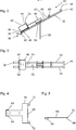
- an elevator shaft 10 for an elevator system has a first, lowermost door opening 12 to which a first, lowermost floor 13 is assigned.
- This first, lowest floor 13 is followed by a second floor 15 with a second door opening 14, a third floor 17 with a third door opening 16, a fourth floor 19 with a fourth door opening 18 and a fifth, uppermost floor 21 with a fifth , top door opening 20.
- a Fig. 1 Installation device 24 shown in simplified form only as a rectangle, slopes upwards into elevator shaft 10.
- the installation device 24 is also supported on a shaft wall 26 opposite the third shaft opening 16.
- An automated assembly device 30, by means of which at least partially automated assembly steps can be carried out in the elevator shaft 10, is suspended from the installation device 24 via a load means 28, for example in the form of a rope or a chain.
- the mounting device 30 can, for example, according to one in FIG WO 2017/016783 A1 be executed assembly device described.
- the mounting device 30 can by means of one in the Fig. 1 Displacement device, not shown, of the installation device 24 in the elevator shaft 10 vertically be relocated.
- the mounting device 30 can thus in the Fig. 1
- the illustrated position of the installation device 24 in the elevator shaft 10 to carry out assembly work at the level of the first and second floors 13, 15.
- the installation device 24 on the fifth floor 21 can be brought into the installation position.
- the assembly device 30 can be temporarily stored on the second floor 15.
- the installation device 24 has been brought back into the installation position on the fifth floor 21, the assembly device 30 can be brought back into the elevator shaft 10 from the second floor 15.
- elevator shafts in which such an installation device and an automated assembly device are used have significantly more than 5 floors, for example at least 15 floors.
- the installation device can move the assembly device in particular over more than 2 floors, for example 30 floors or about 100 m.
- the installation device 24 has a first carrier 32, at the first end 34 of which a support element 36 is pivotably arranged.
- the pivot axis runs in the Fig. 2 perpendicular to the display plane.
- the support element 36 has a first, flat contact element 38 which, in the installation position of the installation device 24, rests against a floor of a story and is fixed to the floor with screws.
- the support element 36 also has a second, flat contact element 40, which is arranged perpendicular to the first contact element 38 and, in the installation position of the installation device 24, lies against the shaft wall forming the threshold with the floor of the floor and is fixed to it with screws.
- a second carrier 33 which is constructed identically to the first carrier 32, is arranged parallel to and at a distance from the first carrier 32.
- the mentioned distance between the two carriers 32, 33 can be between 400 mm and 800 mm, for example.
- a first cross member 44 is arranged, to which a hanging cable (not shown) and a safety line (not shown) for triggering a safety brake of the automated assembly device can be attached.
- the first transverse support 44 is screwed to both supports 32, 33, so that it ensures the above-mentioned distance between the supports 32, 33.
- the first cross member can also be clamped to the carriers using suitable brackets.
- a receiving device 46 In the area of the first support end 34, a receiving device 46 is arranged, which receives a displacement device 48 in the form of an electric winch.
- the receiving device 46 consists of a mainly flat plate made of metal, which is screwed to the carriers 32, 33 and thus also ensures the above-mentioned distance between the carriers 32, 33.
- the receiving device 46 In the Fig. 2 the receiving device 46 is arranged on an upper side 47 of the installation device 24, so that it is arranged in the installation position of the installation device 34 on the upper side 47 of the installation device 24.
- the displacement device 48 is arranged on the receiving device 46 and the two carriers 32, 33, so it is supported in the Fig.
- the receiving device could also be designed in such a way that the displacement device is supported exclusively on the receiving device.
- a region 50 of the displacement device 48 oriented in the direction of the second carrier end 42 of the first carrier 32 is braced with the first and second carriers 32, 33 by means of a tensioning belt 52.
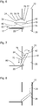
- a deflection roller 54 is arranged approximately centrally between the first carrier end 34 and the second carrier end 42.
- the deflection roller 54 is mounted in a housing 56 which is screwed to the two carriers 32, 33.
- the deflecting roller 54 is arranged in such a way that it dips between the two carriers 32, 33 and deflects a suspension element 28 coming from the displacement device 48 such that it runs vertically downward after the deflecting roller 54.
- the deflection roller 54 is arranged such that, in the installation position of the installation device 24, the support means 28 is arranged approximately in the center of the elevator shaft 10.
- a second cross member 58 is arranged between the deflection roller 54 and the second carrier end 42 and is screwed to the carriers 32, 33.
- the second cross member 58 has an eyelet 60 to which a rope (not shown) can be attached. By means of this cable, the installation device can be pivoted into and out of the installation position in a controlled manner.
- Fig. 3 the displacement device 48 is not shown, so that two first alignment elements 62, designed as openings, of the receiving device 46 can be seen.
- the two first alignment elements 62 act with two second alignment elements 64 designed as extensions one in the Figures 4 and 5 mounting plate 65 shown together.
- the mounting plate 65 is screwed onto the displacement device 48 from below, so that in the assembled state of the installation device 24 it is arranged between the displacement device 48 and the receiving device 46 or the carriers 32, 33.
- the mounting plate 65 has a mainly T-shaped basic shape and consists of a metal plate a few millimeters thick, the second alignment elements 64 being formed by bending over corresponding parts of the metal plate.
- the first alignment elements 62 and the second alignment elements 64 are arranged in such a way that the second alignment elements 64 then dip into the first alignment elements 62 when the mounting plate 65 and thus the displacement device 48 is positioned in a correct mounting position relative to the receiving device 46.
- the immersion can be referred to as a cooperation of the alignment elements 62,64.
- the mounting plate 65 and thus the displacement element 48 also has a guide element 66.
- the guide element 66 is also designed as an extension and is formed analogously to the second alignment elements 64 by bending over a corresponding part of the metal plate.
- the guide element 66 is designed and arranged in such a way that when the displacement device 48 and thus the mounting plate 65 are pushed onto the receiving device 46 and the carriers 32, 33 it dips between the carriers 32, 33 and rests laterally against them.
- the two carriers 32, 33 thus form a guide 70 of the installation device 24, which in an arrangement the displacement device 48 on the installation device 24 interacts with the guide element 66.
- the mounting plate 65 and thus the displacement element 48 also has two sliding elements 72 which are arranged on the two outer ends of the T-shaped mounting plate 65.
- the sliding elements 72 are bent slightly upwards so that they can slide easily on the two carriers 32, 33 when the displacement device 48 is arranged on the installation device 24.
- a deflection element 74 in the form of a deflection roller is initially fixed, for example screwed, directly below the threshold 22 of the floor 17 and thus in the region of the threshold 22 of the door opening 16.
- the installation device 24 is then suspended from a ceiling 78 of the door opening 16 by means of two carrier elements 76 designed as chain hoists in such a way that the first carrier end 34 is arranged outside and the second carrier end 42 is arranged inside the elevator shaft 10.
- the two support elements 76 are fixed at two suspension points 75, 77 of the installation device 24.
- the receiving device 46 serves as the first suspension point 75 and the eyelet 60 on the second cross member 58 serves as the second suspension point 77.
- a third suspension element 80 in the form of a rope is then attached to the first carrier end 34 and guided around the deflection element 74.
- the installation device 24 is pivoted about the ceiling 78 of the door opening 16. The first girder end 34 is thus moved in the direction of the elevator shaft 10.
- the installation device 24 is pivoted until the support element is arranged in a correct position for fixing on the threshold 22 of the door opening 16. If necessary, the length of one or both support elements 76 is also used for this purpose changed or adapted accordingly.
- the installation device 24 is pivoted about the threshold 22 of the door opening 16 into the elevator shaft 10 until the second support end 42 is supported on the shaft wall 26 opposite the door opening 16, whereby the in Fig. 8 illustrated installation position of the installation device 24 is reached.
- the support elements 76, 80 are removed and a cable (not shown) is attached to the eyelet 60 of the installation device 24, with which the pivoting is carried out in a controlled manner.
- the displacement device 48 is arranged on the installation device 24.
- the displacement device 48 with the screwed-on mounting plate 65 is first placed on the receiving device 46 from above.
- the tensioning belt 52 is then loosely guided around the displacement device 48 and the two supports 32, 33 and the tensioning belt 52 is closed.
- the displacement device 48 is pushed into the correct position. Once the correct position has been reached, the displacement device 48 is screwed to the receiving device 46 and the tensioning belt 52 is tightened. The displacement device 48 is thus securely fixed on the installation device 24.
- the entire installation device 24 is pivoted with the above-mentioned cable in the direction of the door opening 16 and then brought back into the installation position.
- the pivoting in the direction of the door opening 16 can be repeated, for example if further parts, which have been transported up from further down in the elevator shaft 10 by means of the suspension element 28, are to be arranged on the installation device 24.
Landscapes
- Engineering & Computer Science (AREA)
- Structural Engineering (AREA)
- Civil Engineering (AREA)
- Architecture (AREA)
- Transportation (AREA)
- Automation & Control Theory (AREA)
- Mechanical Engineering (AREA)
- Elevator Door Apparatuses (AREA)
- Lift-Guide Devices, And Elevator Ropes And Cables (AREA)
Claims (6)
- Dispositif d'installation (24) à utiliser dans une cage d'ascenseur (10) comportant- un premier support (32) qui présente une première extrémité de support (34) et une seconde extrémité de support (42),- un élément de soutien (36) qui est disposé de manière pivotante sur la première extrémité de support (34) et- un dispositif de réception (46) pour recevoir un dispositif de déplacement (48) permettant de déplacer un matériau d'installation (30) dans la cage d'ascenseur (10),- l'élément de soutien (36) étant conçu et agencé de telle sorte que le premier support (32) peut être soutenu sur l'élément de soutien (36) dans une zone d'une ouverture de porte (12, 14, 16, 18, 20) de la cage d'ascenseur (10) dans une position d'installation du dispositif d'installation (24),- la seconde extrémité de support (42) étant conçue de telle sorte que le premier support (32) peut être au moins indirectement soutenu sur la seconde extrémité de support (42) sur une paroi de cage (26) opposée à l'une desdites ouvertures de porte (12, 14, 16, 18, 20) de la cage d'ascenseur (10) dans la position d'installation du dispositif d'installation (24),le dispositif de réception (46) étant conçu pour recevoir le dispositif de déplacement (48) et étant agencé dans la position d'installation du dispositif d'installation (24) sur un côté supérieur (47) du dispositif d'installation (24) de telle sorte qu'un dispositif de déplacement (48) reçu par le dispositif de réception (46) est soutenu par le haut sur le dispositif de réception (46) dans la position d'installation du dispositif d'installation (24), et le dispositif d'installation (24) présentant une poulie de renvoi (54) qui est conçue et agencée de manière à réorienter un moyen de support (28) du dispositif de déplacement (48) reçu par le dispositif de réception (46),
le dispositif d'installation (24) présentant un dispositif de déplacement (48, 65) reçu par le dispositif de réception (46) et le dispositif de déplacement (48, 65) présentant au moins un élément de guidage (66), lequel est conçu et agencé de manière à interagir avec un guide (70) du dispositif d'installation (24) lorsque le dispositif de déplacement (48, 65) est agencé sur le dispositif de réception (46). - Dispositif d'installation selon la revendication 1,
caractérisé en ce que
l'élément de soutien (36) est conçu et agencé de telle sorte que le premier support (32) peut être soutenu sur l'élément de soutien (36) sur un seuil (22) d'une ouverture de porte (12, 14, 16, 18, 20) de la cage d'ascenseur (10) dans la position d'installation du dispositif d'installation (24). - Dispositif d'installation selon la revendication 1 ou 2,
caractérisé en ce que
le dispositif de réception (46) présente au moins un premier élément d'alignement (62) pour recevoir le dispositif de déplacement (48), lequel élément d'alignement est conçu et agencé de manière à coopérer avec un second élément d'alignement (64) du dispositif de déplacement (48, 65) dans une position de montage correcte du dispositif de déplacement (48, 65) par rapport au dispositif de réception (46). - Dispositif d'installation selon la revendication 1, 2 ou 3,
caractérisé en ce que
le dispositif d'installation (24) présente un second support (33) qui est disposé à une distance parallèle au premier support (32) et les deux supports (32, 33) forment ledit guidage (70) du dispositif d'installation (24). - Dispositif d'installation selon l'une des revendications 1 à 4,
caractérisé en ce que
le dispositif de déplacement (48, 65) présente au moins un élément coulissant (72) qui est conçu et agencé de telle sorte que, lorsque le dispositif de déplacement (48, 65) est disposé sur le dispositif de réception (46), ledit élément coulissant glisse le long du dispositif de réception (46) et/ou du premier support (32). - Dispositif d'installation selon l'une des revendications 1 à 5,
caractérisé en ce
qu'une zone (50) du dispositif de déplacement (48, 65) alignée en direction de la seconde extrémité de support (42) du premier support (32) est reliée de façon contrainte au premier support (32) par une sangle de serrage (52).
Applications Claiming Priority (2)
| Application Number | Priority Date | Filing Date | Title |
|---|---|---|---|
| EP17190944 | 2017-09-13 | ||
| PCT/EP2018/074356 WO2019052970A1 (fr) | 2017-09-13 | 2018-09-11 | Dispositif d'installation et procédé permettant de mettre un dispositif d'installation dans une position d'installation dans une cage d'ascenseur |
Publications (2)
| Publication Number | Publication Date |
|---|---|
| EP3681836A1 EP3681836A1 (fr) | 2020-07-22 |
| EP3681836B1 true EP3681836B1 (fr) | 2021-06-23 |
Family
ID=59858939
Family Applications (1)
| Application Number | Title | Priority Date | Filing Date |
|---|---|---|---|
| EP18762878.9A Active EP3681836B1 (fr) | 2017-09-13 | 2018-09-11 | Dispositif d'installation pour une utlisation dans une cage d'ascenseur |
Country Status (5)
| Country | Link |
|---|---|
| US (1) | US11655123B2 (fr) |
| EP (1) | EP3681836B1 (fr) |
| CN (1) | CN111094167B (fr) |
| SG (1) | SG11202001099SA (fr) |
| WO (1) | WO2019052970A1 (fr) |
Families Citing this family (2)
| Publication number | Priority date | Publication date | Assignee | Title |
|---|---|---|---|---|
| CN113544077B (zh) | 2019-03-27 | 2023-04-18 | 因温特奥股份公司 | 用于在电梯系统的电梯井道中执行安装过程的安装设备和方法 |
| CN114728769A (zh) * | 2019-11-08 | 2022-07-08 | 因温特奥股份公司 | 用于电梯竖井中的安装装置 |
Family Cites Families (14)
| Publication number | Priority date | Publication date | Assignee | Title |
|---|---|---|---|---|
| US5033586A (en) * | 1990-07-11 | 1991-07-23 | Otis Elevator Company | Construction elevator assembly |
| US8646224B2 (en) | 2008-09-17 | 2014-02-11 | Wurtec Elevator Products & Services | Construction apparatus |
| FI20090085L (fi) * | 2009-03-06 | 2010-09-30 | Kone Corp | Hissijärjestely ja menetelmä |
| CN201478117U (zh) * | 2009-08-11 | 2010-05-19 | 银河电气科技有限公司 | 一种铁芯翻转装置 |
| FI20090389A (fi) * | 2009-10-23 | 2011-04-24 | Kone Corp | Menetelmä hissin valmistamisessa |
| JP2011225336A (ja) * | 2010-04-20 | 2011-11-10 | Mitsubishi Electric Corp | クライミングエレベータの機械台装置 |
| FI125115B (fi) * | 2010-12-31 | 2015-06-15 | Kone Corp | Menetelmä ja hissijärjestely |
| EP2636629B1 (fr) | 2012-03-06 | 2015-05-06 | KONE Corporation | Procédé et agencement d'ascenseur |
| DE102012111622A1 (de) * | 2012-11-29 | 2014-06-05 | Thyssenkrupp Elevator Ag | Aufzuganlage für ein im Bau befindliches Gebäude |
| PT3019428T (pt) * | 2013-07-10 | 2017-07-14 | Inventio Ag | Dispositivo de proteção contra quedas para uma plataforma |
| US10024488B2 (en) * | 2014-10-06 | 2018-07-17 | Wurtec, Incorporated | Three-beam construction apparatus |
| CN204426504U (zh) * | 2015-01-29 | 2015-07-01 | 张荣轩 | 一种农村杀猪专用装置 |
| EP3325395B1 (fr) | 2015-07-24 | 2019-11-20 | Inventio AG | Dispositif de montage automatise destine a executer des procedures d'installation dans une cabine d'un ascenseur |
| EP3388379A1 (fr) * | 2017-04-10 | 2018-10-17 | KONE Corporation | Agencement d'ascenseur et procédé |
-
2018
- 2018-09-11 US US16/640,390 patent/US11655123B2/en active Active
- 2018-09-11 WO PCT/EP2018/074356 patent/WO2019052970A1/fr unknown
- 2018-09-11 EP EP18762878.9A patent/EP3681836B1/fr active Active
- 2018-09-11 CN CN201880059839.9A patent/CN111094167B/zh active Active
- 2018-09-11 SG SG11202001099SA patent/SG11202001099SA/en unknown
Also Published As
| Publication number | Publication date |
|---|---|
| EP3681836A1 (fr) | 2020-07-22 |
| SG11202001099SA (en) | 2020-03-30 |
| WO2019052970A1 (fr) | 2019-03-21 |
| CN111094167B (zh) | 2022-07-12 |
| CN111094167A (zh) | 2020-05-01 |
| US11655123B2 (en) | 2023-05-23 |
| US20200354197A1 (en) | 2020-11-12 |
Similar Documents
| Publication | Publication Date | Title |
|---|---|---|
| EP3390263B1 (fr) | Procédé de montage d'un ascenseur | |
| EP2935075B1 (fr) | Procédé d'installation pour un ascenseur | |
| EP3083479B1 (fr) | Procédé d'installation d'une installation d'ascenseur et dispositif | |
| EP3212556B1 (fr) | Procédé d'installation de rails de guidage | |
| DE2413450A1 (de) | Montagegeruest zum installieren der fuehrungsschienen eines aufzugs im aufzugsschacht eines gebaeudes und verfahren zur anwendung desselben | |
| DE112012006449B4 (de) | Zugmaschinenbasis eines Fahrstuhls und Fahrstuhlvorrichtung | |
| EP3681836B1 (fr) | Dispositif d'installation pour une utlisation dans une cage d'ascenseur | |
| EP3052420B1 (fr) | Installation d'ascenseur | |
| DE102009026866A1 (de) | Verfahren zum Einsetzen, Abnehmen oder Umsetzen einer Wartungsgondel an einer Überlandleitung | |
| EP3873840B1 (fr) | Procédé d'installation d'une installation d'ascenseur | |
| EP3947237B1 (fr) | Dispositif de montage, procédé de mise en oeuvre d'un processus d'installation dans une cage d'ascenseur d'une installation d'ascenseur | |
| EP3119713A1 (fr) | Ascenseur équipé d'un dispositif de tension de câble de compensation | |
| EP2714567B1 (fr) | Etrier d'entraînement faisant partie d'un système d'ascenseur | |
| DE202017101470U1 (de) | Grabenverbau zum Verbau von Rohrleitungsgräben | |
| EP3538466B1 (fr) | Cabine d'ascenseur pour une system d'ascenseur | |
| EP1589627B1 (fr) | Dispositif de levage et de fixation pour barres omnibus | |
| DE202014102110U1 (de) | Aufzuganlage | |
| EP1717186A1 (fr) | Procédé et dispositif pour installer les guides d' ascenseur dans la gaine | |
| EP4054967B1 (fr) | Dispositif d'installation destiné à l'utilisation dans une cage d'ascenseur | |
| DE112016007111T5 (de) | Kabinenbefestigungseinrichtung für einen Aufzug | |
| DE202015106315U1 (de) | Signal- oder Beleuchtungsmast | |
| EP3947230A2 (fr) | Ensemble bande de mesure destiné à être utilisé dans un ascenseur et procédé permettant d'installer et de faire fonctionner un ascenseur | |
| DE10154171A1 (de) | Modernisierung von Hydraulikaufzügen | |
| WO2018219851A1 (fr) | Plate-forme supplémentaire ajoutée à une plate-forme de travail | |
| WO2019001889A1 (fr) | Système d'ascenseur |
Legal Events
| Date | Code | Title | Description |
|---|---|---|---|
| STAA | Information on the status of an ep patent application or granted ep patent |
Free format text: STATUS: UNKNOWN |
|
| STAA | Information on the status of an ep patent application or granted ep patent |
Free format text: STATUS: THE INTERNATIONAL PUBLICATION HAS BEEN MADE |
|
| PUAI | Public reference made under article 153(3) epc to a published international application that has entered the european phase |
Free format text: ORIGINAL CODE: 0009012 |
|
| STAA | Information on the status of an ep patent application or granted ep patent |
Free format text: STATUS: REQUEST FOR EXAMINATION WAS MADE |
|
| 17P | Request for examination filed |
Effective date: 20200130 |
|
| AK | Designated contracting states |
Kind code of ref document: A1 Designated state(s): AL AT BE BG CH CY CZ DE DK EE ES FI FR GB GR HR HU IE IS IT LI LT LU LV MC MK MT NL NO PL PT RO RS SE SI SK SM TR |
|
| AX | Request for extension of the european patent |
Extension state: BA ME |
|
| DAV | Request for validation of the european patent (deleted) | ||
| DAX | Request for extension of the european patent (deleted) | ||
| GRAP | Despatch of communication of intention to grant a patent |
Free format text: ORIGINAL CODE: EPIDOSNIGR1 |
|
| STAA | Information on the status of an ep patent application or granted ep patent |
Free format text: STATUS: GRANT OF PATENT IS INTENDED |
|
| INTG | Intention to grant announced |
Effective date: 20210401 |
|
| GRAS | Grant fee paid |
Free format text: ORIGINAL CODE: EPIDOSNIGR3 |
|
| GRAA | (expected) grant |
Free format text: ORIGINAL CODE: 0009210 |
|
| STAA | Information on the status of an ep patent application or granted ep patent |
Free format text: STATUS: THE PATENT HAS BEEN GRANTED |
|
| AK | Designated contracting states |
Kind code of ref document: B1 Designated state(s): AL AT BE BG CH CY CZ DE DK EE ES FI FR GB GR HR HU IE IS IT LI LT LU LV MC MK MT NL NO PL PT RO RS SE SI SK SM TR |
|
| REG | Reference to a national code |
Ref country code: GB Ref legal event code: FG4D Free format text: NOT ENGLISH |
|
| REG | Reference to a national code |
Ref country code: CH Ref legal event code: EP |
|
| REG | Reference to a national code |
Ref country code: DE Ref legal event code: R096 Ref document number: 502018005857 Country of ref document: DE Ref country code: AT Ref legal event code: REF Ref document number: 1404158 Country of ref document: AT Kind code of ref document: T Effective date: 20210715 |
|
| REG | Reference to a national code |
Ref country code: IE Ref legal event code: FG4D Free format text: LANGUAGE OF EP DOCUMENT: GERMAN |
|
| REG | Reference to a national code |
Ref country code: LT Ref legal event code: MG9D |
|
| PG25 | Lapsed in a contracting state [announced via postgrant information from national office to epo] |
Ref country code: FI Free format text: LAPSE BECAUSE OF FAILURE TO SUBMIT A TRANSLATION OF THE DESCRIPTION OR TO PAY THE FEE WITHIN THE PRESCRIBED TIME-LIMIT Effective date: 20210623 Ref country code: HR Free format text: LAPSE BECAUSE OF FAILURE TO SUBMIT A TRANSLATION OF THE DESCRIPTION OR TO PAY THE FEE WITHIN THE PRESCRIBED TIME-LIMIT Effective date: 20210623 Ref country code: LT Free format text: LAPSE BECAUSE OF FAILURE TO SUBMIT A TRANSLATION OF THE DESCRIPTION OR TO PAY THE FEE WITHIN THE PRESCRIBED TIME-LIMIT Effective date: 20210623 Ref country code: BG Free format text: LAPSE BECAUSE OF FAILURE TO SUBMIT A TRANSLATION OF THE DESCRIPTION OR TO PAY THE FEE WITHIN THE PRESCRIBED TIME-LIMIT Effective date: 20210923 |
|
| PG25 | Lapsed in a contracting state [announced via postgrant information from national office to epo] |
Ref country code: NO Free format text: LAPSE BECAUSE OF FAILURE TO SUBMIT A TRANSLATION OF THE DESCRIPTION OR TO PAY THE FEE WITHIN THE PRESCRIBED TIME-LIMIT Effective date: 20210923 Ref country code: LV Free format text: LAPSE BECAUSE OF FAILURE TO SUBMIT A TRANSLATION OF THE DESCRIPTION OR TO PAY THE FEE WITHIN THE PRESCRIBED TIME-LIMIT Effective date: 20210623 Ref country code: SE Free format text: LAPSE BECAUSE OF FAILURE TO SUBMIT A TRANSLATION OF THE DESCRIPTION OR TO PAY THE FEE WITHIN THE PRESCRIBED TIME-LIMIT Effective date: 20210623 Ref country code: RS Free format text: LAPSE BECAUSE OF FAILURE TO SUBMIT A TRANSLATION OF THE DESCRIPTION OR TO PAY THE FEE WITHIN THE PRESCRIBED TIME-LIMIT Effective date: 20210623 Ref country code: GR Free format text: LAPSE BECAUSE OF FAILURE TO SUBMIT A TRANSLATION OF THE DESCRIPTION OR TO PAY THE FEE WITHIN THE PRESCRIBED TIME-LIMIT Effective date: 20210924 |
|
| REG | Reference to a national code |
Ref country code: NL Ref legal event code: MP Effective date: 20210623 |
|
| PG25 | Lapsed in a contracting state [announced via postgrant information from national office to epo] |
Ref country code: PT Free format text: LAPSE BECAUSE OF FAILURE TO SUBMIT A TRANSLATION OF THE DESCRIPTION OR TO PAY THE FEE WITHIN THE PRESCRIBED TIME-LIMIT Effective date: 20211025 Ref country code: NL Free format text: LAPSE BECAUSE OF FAILURE TO SUBMIT A TRANSLATION OF THE DESCRIPTION OR TO PAY THE FEE WITHIN THE PRESCRIBED TIME-LIMIT Effective date: 20210623 Ref country code: RO Free format text: LAPSE BECAUSE OF FAILURE TO SUBMIT A TRANSLATION OF THE DESCRIPTION OR TO PAY THE FEE WITHIN THE PRESCRIBED TIME-LIMIT Effective date: 20210623 Ref country code: SM Free format text: LAPSE BECAUSE OF FAILURE TO SUBMIT A TRANSLATION OF THE DESCRIPTION OR TO PAY THE FEE WITHIN THE PRESCRIBED TIME-LIMIT Effective date: 20210623 Ref country code: CZ Free format text: LAPSE BECAUSE OF FAILURE TO SUBMIT A TRANSLATION OF THE DESCRIPTION OR TO PAY THE FEE WITHIN THE PRESCRIBED TIME-LIMIT Effective date: 20210623 Ref country code: SK Free format text: LAPSE BECAUSE OF FAILURE TO SUBMIT A TRANSLATION OF THE DESCRIPTION OR TO PAY THE FEE WITHIN THE PRESCRIBED TIME-LIMIT Effective date: 20210623 Ref country code: EE Free format text: LAPSE BECAUSE OF FAILURE TO SUBMIT A TRANSLATION OF THE DESCRIPTION OR TO PAY THE FEE WITHIN THE PRESCRIBED TIME-LIMIT Effective date: 20210623 Ref country code: ES Free format text: LAPSE BECAUSE OF FAILURE TO SUBMIT A TRANSLATION OF THE DESCRIPTION OR TO PAY THE FEE WITHIN THE PRESCRIBED TIME-LIMIT Effective date: 20210623 |
|
| PG25 | Lapsed in a contracting state [announced via postgrant information from national office to epo] |
Ref country code: PL Free format text: LAPSE BECAUSE OF FAILURE TO SUBMIT A TRANSLATION OF THE DESCRIPTION OR TO PAY THE FEE WITHIN THE PRESCRIBED TIME-LIMIT Effective date: 20210623 |
|
| REG | Reference to a national code |
Ref country code: DE Ref legal event code: R097 Ref document number: 502018005857 Country of ref document: DE |
|
| PG25 | Lapsed in a contracting state [announced via postgrant information from national office to epo] |
Ref country code: DK Free format text: LAPSE BECAUSE OF FAILURE TO SUBMIT A TRANSLATION OF THE DESCRIPTION OR TO PAY THE FEE WITHIN THE PRESCRIBED TIME-LIMIT Effective date: 20210623 |
|
| PLBE | No opposition filed within time limit |
Free format text: ORIGINAL CODE: 0009261 |
|
| STAA | Information on the status of an ep patent application or granted ep patent |
Free format text: STATUS: NO OPPOSITION FILED WITHIN TIME LIMIT |
|
| REG | Reference to a national code |
Ref country code: BE Ref legal event code: MM Effective date: 20210930 |
|
| 26N | No opposition filed |
Effective date: 20220324 |
|
| PG25 | Lapsed in a contracting state [announced via postgrant information from national office to epo] |
Ref country code: MC Free format text: LAPSE BECAUSE OF FAILURE TO SUBMIT A TRANSLATION OF THE DESCRIPTION OR TO PAY THE FEE WITHIN THE PRESCRIBED TIME-LIMIT Effective date: 20210623 Ref country code: AL Free format text: LAPSE BECAUSE OF FAILURE TO SUBMIT A TRANSLATION OF THE DESCRIPTION OR TO PAY THE FEE WITHIN THE PRESCRIBED TIME-LIMIT Effective date: 20210623 |
|
| PG25 | Lapsed in a contracting state [announced via postgrant information from national office to epo] |
Ref country code: LU Free format text: LAPSE BECAUSE OF NON-PAYMENT OF DUE FEES Effective date: 20210911 Ref country code: IT Free format text: LAPSE BECAUSE OF FAILURE TO SUBMIT A TRANSLATION OF THE DESCRIPTION OR TO PAY THE FEE WITHIN THE PRESCRIBED TIME-LIMIT Effective date: 20210623 Ref country code: IE Free format text: LAPSE BECAUSE OF NON-PAYMENT OF DUE FEES Effective date: 20210911 Ref country code: BE Free format text: LAPSE BECAUSE OF NON-PAYMENT OF DUE FEES Effective date: 20210930 |
|
| PG25 | Lapsed in a contracting state [announced via postgrant information from national office to epo] |
Ref country code: CY Free format text: LAPSE BECAUSE OF FAILURE TO SUBMIT A TRANSLATION OF THE DESCRIPTION OR TO PAY THE FEE WITHIN THE PRESCRIBED TIME-LIMIT Effective date: 20210623 |
|
| PG25 | Lapsed in a contracting state [announced via postgrant information from national office to epo] |
Ref country code: HU Free format text: LAPSE BECAUSE OF FAILURE TO SUBMIT A TRANSLATION OF THE DESCRIPTION OR TO PAY THE FEE WITHIN THE PRESCRIBED TIME-LIMIT; INVALID AB INITIO Effective date: 20180911 |
|
| PGFP | Annual fee paid to national office [announced via postgrant information from national office to epo] |
Ref country code: TR Payment date: 20230828 Year of fee payment: 6 Ref country code: GB Payment date: 20230926 Year of fee payment: 6 |
|
| PGFP | Annual fee paid to national office [announced via postgrant information from national office to epo] |
Ref country code: FR Payment date: 20230926 Year of fee payment: 6 Ref country code: DE Payment date: 20230928 Year of fee payment: 6 |
|
| PGFP | Annual fee paid to national office [announced via postgrant information from national office to epo] |
Ref country code: CH Payment date: 20231001 Year of fee payment: 6 |
|
| PG25 | Lapsed in a contracting state [announced via postgrant information from national office to epo] |
Ref country code: MK Free format text: LAPSE BECAUSE OF FAILURE TO SUBMIT A TRANSLATION OF THE DESCRIPTION OR TO PAY THE FEE WITHIN THE PRESCRIBED TIME-LIMIT Effective date: 20210623 |