EP3681749B1 - Verfahren und vorrichtung zur bestimmung einer radschlupfinformation eines elektrisch angetriebenen rades eines kraftfahrzeugs - Google Patents
Verfahren und vorrichtung zur bestimmung einer radschlupfinformation eines elektrisch angetriebenen rades eines kraftfahrzeugs Download PDFInfo
- Publication number
- EP3681749B1 EP3681749B1 EP18766148.3A EP18766148A EP3681749B1 EP 3681749 B1 EP3681749 B1 EP 3681749B1 EP 18766148 A EP18766148 A EP 18766148A EP 3681749 B1 EP3681749 B1 EP 3681749B1
- Authority
- EP
- European Patent Office
- Prior art keywords
- wheel
- speed
- motor
- actual
- theo
- Prior art date
- Legal status (The legal status is an assumption and is not a legal conclusion. Google has not performed a legal analysis and makes no representation as to the accuracy of the status listed.)
- Active
Links
Images
Classifications
-
- B—PERFORMING OPERATIONS; TRANSPORTING
- B60—VEHICLES IN GENERAL
- B60L—PROPULSION OF ELECTRICALLY-PROPELLED VEHICLES; SUPPLYING ELECTRIC POWER FOR AUXILIARY EQUIPMENT OF ELECTRICALLY-PROPELLED VEHICLES; ELECTRODYNAMIC BRAKE SYSTEMS FOR VEHICLES IN GENERAL; MAGNETIC SUSPENSION OR LEVITATION FOR VEHICLES; MONITORING OPERATING VARIABLES OF ELECTRICALLY-PROPELLED VEHICLES; ELECTRIC SAFETY DEVICES FOR ELECTRICALLY-PROPELLED VEHICLES
- B60L3/00—Electric devices on electrically-propelled vehicles for safety purposes; Monitoring operating variables, e.g. speed, deceleration or energy consumption
- B60L3/10—Indicating wheel slip ; Correction of wheel slip
- B60L3/104—Indicating wheel slip ; Correction of wheel slip by indirect measurement of vehicle speed
-
- B—PERFORMING OPERATIONS; TRANSPORTING
- B60—VEHICLES IN GENERAL
- B60T—VEHICLE BRAKE CONTROL SYSTEMS OR PARTS THEREOF; BRAKE CONTROL SYSTEMS OR PARTS THEREOF, IN GENERAL; ARRANGEMENT OF BRAKING ELEMENTS ON VEHICLES IN GENERAL; PORTABLE DEVICES FOR PREVENTING UNWANTED MOVEMENT OF VEHICLES; VEHICLE MODIFICATIONS TO FACILITATE COOLING OF BRAKES
- B60T8/00—Arrangements for adjusting wheel-braking force to meet varying vehicular or ground-surface conditions, e.g. limiting or varying distribution of braking force
- B60T8/17—Using electrical or electronic regulation means to control braking
- B60T8/176—Brake regulation specially adapted to prevent excessive wheel slip during vehicle deceleration, e.g. ABS
- B60T8/1761—Brake regulation specially adapted to prevent excessive wheel slip during vehicle deceleration, e.g. ABS responsive to wheel or brake dynamics, e.g. wheel slip, wheel acceleration or rate of change of brake fluid pressure
- B60T8/17616—Microprocessor-based systems
-
- B—PERFORMING OPERATIONS; TRANSPORTING
- B60—VEHICLES IN GENERAL
- B60K—ARRANGEMENT OR MOUNTING OF PROPULSION UNITS OR OF TRANSMISSIONS IN VEHICLES; ARRANGEMENT OR MOUNTING OF PLURAL DIVERSE PRIME-MOVERS IN VEHICLES; AUXILIARY DRIVES FOR VEHICLES; INSTRUMENTATION OR DASHBOARDS FOR VEHICLES; ARRANGEMENTS IN CONNECTION WITH COOLING, AIR INTAKE, GAS EXHAUST OR FUEL SUPPLY OF PROPULSION UNITS IN VEHICLES
- B60K7/00—Disposition of motor in, or adjacent to, traction wheel
- B60K7/0007—Disposition of motor in, or adjacent to, traction wheel the motor being electric
-
- B—PERFORMING OPERATIONS; TRANSPORTING
- B60—VEHICLES IN GENERAL
- B60L—PROPULSION OF ELECTRICALLY-PROPELLED VEHICLES; SUPPLYING ELECTRIC POWER FOR AUXILIARY EQUIPMENT OF ELECTRICALLY-PROPELLED VEHICLES; ELECTRODYNAMIC BRAKE SYSTEMS FOR VEHICLES IN GENERAL; MAGNETIC SUSPENSION OR LEVITATION FOR VEHICLES; MONITORING OPERATING VARIABLES OF ELECTRICALLY-PROPELLED VEHICLES; ELECTRIC SAFETY DEVICES FOR ELECTRICALLY-PROPELLED VEHICLES
- B60L3/00—Electric devices on electrically-propelled vehicles for safety purposes; Monitoring operating variables, e.g. speed, deceleration or energy consumption
- B60L3/0023—Detecting, eliminating, remedying or compensating for drive train abnormalities, e.g. failures within the drive train
- B60L3/0038—Detecting, eliminating, remedying or compensating for drive train abnormalities, e.g. failures within the drive train relating to sensors
-
- B—PERFORMING OPERATIONS; TRANSPORTING
- B60—VEHICLES IN GENERAL
- B60L—PROPULSION OF ELECTRICALLY-PROPELLED VEHICLES; SUPPLYING ELECTRIC POWER FOR AUXILIARY EQUIPMENT OF ELECTRICALLY-PROPELLED VEHICLES; ELECTRODYNAMIC BRAKE SYSTEMS FOR VEHICLES IN GENERAL; MAGNETIC SUSPENSION OR LEVITATION FOR VEHICLES; MONITORING OPERATING VARIABLES OF ELECTRICALLY-PROPELLED VEHICLES; ELECTRIC SAFETY DEVICES FOR ELECTRICALLY-PROPELLED VEHICLES
- B60L3/00—Electric devices on electrically-propelled vehicles for safety purposes; Monitoring operating variables, e.g. speed, deceleration or energy consumption
- B60L3/10—Indicating wheel slip ; Correction of wheel slip
- B60L3/102—Indicating wheel slip ; Correction of wheel slip of individual wheels
-
- B—PERFORMING OPERATIONS; TRANSPORTING
- B60—VEHICLES IN GENERAL
- B60T—VEHICLE BRAKE CONTROL SYSTEMS OR PARTS THEREOF; BRAKE CONTROL SYSTEMS OR PARTS THEREOF, IN GENERAL; ARRANGEMENT OF BRAKING ELEMENTS ON VEHICLES IN GENERAL; PORTABLE DEVICES FOR PREVENTING UNWANTED MOVEMENT OF VEHICLES; VEHICLE MODIFICATIONS TO FACILITATE COOLING OF BRAKES
- B60T8/00—Arrangements for adjusting wheel-braking force to meet varying vehicular or ground-surface conditions, e.g. limiting or varying distribution of braking force
- B60T8/17—Using electrical or electronic regulation means to control braking
- B60T8/175—Brake regulation specially adapted to prevent excessive wheel spin during vehicle acceleration, e.g. for traction control
-
- B—PERFORMING OPERATIONS; TRANSPORTING
- B60—VEHICLES IN GENERAL
- B60L—PROPULSION OF ELECTRICALLY-PROPELLED VEHICLES; SUPPLYING ELECTRIC POWER FOR AUXILIARY EQUIPMENT OF ELECTRICALLY-PROPELLED VEHICLES; ELECTRODYNAMIC BRAKE SYSTEMS FOR VEHICLES IN GENERAL; MAGNETIC SUSPENSION OR LEVITATION FOR VEHICLES; MONITORING OPERATING VARIABLES OF ELECTRICALLY-PROPELLED VEHICLES; ELECTRIC SAFETY DEVICES FOR ELECTRICALLY-PROPELLED VEHICLES
- B60L2240/00—Control parameters of input or output; Target parameters
- B60L2240/40—Drive Train control parameters
- B60L2240/42—Drive Train control parameters related to electric machines
- B60L2240/421—Speed
-
- B—PERFORMING OPERATIONS; TRANSPORTING
- B60—VEHICLES IN GENERAL
- B60L—PROPULSION OF ELECTRICALLY-PROPELLED VEHICLES; SUPPLYING ELECTRIC POWER FOR AUXILIARY EQUIPMENT OF ELECTRICALLY-PROPELLED VEHICLES; ELECTRODYNAMIC BRAKE SYSTEMS FOR VEHICLES IN GENERAL; MAGNETIC SUSPENSION OR LEVITATION FOR VEHICLES; MONITORING OPERATING VARIABLES OF ELECTRICALLY-PROPELLED VEHICLES; ELECTRIC SAFETY DEVICES FOR ELECTRICALLY-PROPELLED VEHICLES
- B60L2240/00—Control parameters of input or output; Target parameters
- B60L2240/40—Drive Train control parameters
- B60L2240/42—Drive Train control parameters related to electric machines
- B60L2240/427—Voltage
-
- B—PERFORMING OPERATIONS; TRANSPORTING
- B60—VEHICLES IN GENERAL
- B60L—PROPULSION OF ELECTRICALLY-PROPELLED VEHICLES; SUPPLYING ELECTRIC POWER FOR AUXILIARY EQUIPMENT OF ELECTRICALLY-PROPELLED VEHICLES; ELECTRODYNAMIC BRAKE SYSTEMS FOR VEHICLES IN GENERAL; MAGNETIC SUSPENSION OR LEVITATION FOR VEHICLES; MONITORING OPERATING VARIABLES OF ELECTRICALLY-PROPELLED VEHICLES; ELECTRIC SAFETY DEVICES FOR ELECTRICALLY-PROPELLED VEHICLES
- B60L2240/00—Control parameters of input or output; Target parameters
- B60L2240/40—Drive Train control parameters
- B60L2240/42—Drive Train control parameters related to electric machines
- B60L2240/429—Current
-
- B—PERFORMING OPERATIONS; TRANSPORTING
- B60—VEHICLES IN GENERAL
- B60L—PROPULSION OF ELECTRICALLY-PROPELLED VEHICLES; SUPPLYING ELECTRIC POWER FOR AUXILIARY EQUIPMENT OF ELECTRICALLY-PROPELLED VEHICLES; ELECTRODYNAMIC BRAKE SYSTEMS FOR VEHICLES IN GENERAL; MAGNETIC SUSPENSION OR LEVITATION FOR VEHICLES; MONITORING OPERATING VARIABLES OF ELECTRICALLY-PROPELLED VEHICLES; ELECTRIC SAFETY DEVICES FOR ELECTRICALLY-PROPELLED VEHICLES
- B60L2240/00—Control parameters of input or output; Target parameters
- B60L2240/40—Drive Train control parameters
- B60L2240/46—Drive Train control parameters related to wheels
- B60L2240/461—Speed
Definitions
- the invention relates to a method for determining wheel slip information of an electrically driven wheel of a motor vehicle, in particular after a failure of a wheel speed sensor assigned to the wheel, according to the type specified in patent claims 1 and 2.
- the invention is based on the object of specifying a method by means of which substitute information about the adhesion situation (slip) of the wheels of the motor vehicle can be generated in the event of a failure of a wheel speed sensor.
- the speed of the electric motor detected while the motor vehicle is moving is used to determine the wheel speed.
- the method now advantageously ensures that substitute slip information can be generated even if a wheel speed sensor fails. i.e. redundant wheel slip information is made available by means of the method according to the invention. This has the positive effect that - since replacement slip information is now available - deactivation is not absolutely necessary in the case of piloted or (partially) autonomous driving.
- each wheel of the motor vehicle is assigned an electric motor, ie each wheel of the motor vehicle is a driven by a separate electric motor.
- a comparison is carried out in a regulation/control unit by comparing the determined theoretical wheel speed n wheel,theo with the determined actual wheel speed n wheel,actual . If the comparison shows that the calculated theoretical wheel speed n wheel,theo deviates significantly from the determined actual wheel speed n wheel, actual, then it is determined as wheel slip information that the wheel in question is slipping.
- the wheels of an axle are driven by a common electric motor and an axle differential is arranged between the wheels of the axle.
- the translation of the axle differential is referred to below as i A.
- a comparison is then carried out in a regulation/control unit by comparing the determined theoretical wheel speed n wheel,theo of the wheels of the axle with the determined theoretical actual wheel speed n wheel,actual . If the comparison shows that the determined theoretical wheel speed n wheel,theo of one or both wheels deviates significantly from the determined actual wheel speed n wheel, actual, wheel slip information is determined that the affected wheel or both wheels of the axle are slipping.
- the speed difference ⁇ n between the wheels of an axle can be detected in various ways, e.g. B. by a separate sensor specially provided for this purpose.
- the determined theoretical wheel speeds of the wheels on one axle are preferably also compared with one another.
- B. the comparison for the wheels of an axle that n wheel, left, theo > n wheel, right, theo this is an indication that in the case of acceleration or driving at constant speed, the left wheel is in slip and must be braked or in the event of deceleration, ie active braking or engine boost recuperation, that the right wheel is locked and the pressure on the brake must be released or the engine boost/recuperation must be reduced.
- the speed of the electric motor is preferably determined from the current profile and/or voltage drop and/or from information about the motor control.
- An alternative embodiment provides that the speed of the electric motor via a sensor, z. B. in the form of a Hall sensor is determined.
- n wheel there is a significant deviation of the determined theoretical wheel speed n wheel,theo from the determined actual wheel speed n wheel, actual if the following applies to the wheel speeds: n wheel , Is ⁇ 0.9 n wheel , theo or n wheel , Is ⁇ 1.1 n wheel , theo
- a device for carrying out the method according to the invention for determining wheel slip information of an electrically driven Wheel of a motor vehicle comprises an electric motor for driving the wheel, a wheel speed sensor associated with the wheel and means for detecting the speed of the electric motor. Furthermore, the device includes a regulation/control unit to which the current motor vehicle speed and the output signals of the wheel speed sensor assigned to the wheel are made available as input signals. According to the invention, the recorded data on the speed of the electric motor are also made available to the regulation/control unit as a further input variable.
- the determination of redundant wheel slip information is made possible on the basis of the information about the rotational speed of the electric motor that is now made available to the control unit as a further input variable.
- the means for detecting the speed of the electric motor are preferably designed in such a way that they generate the speed of the electric motor from the current profile and/or voltage drop and/or from information from the motor control.
- An alternative embodiment provides that the means for detecting the speed of the electric motor are designed in the form of a separate sensor.
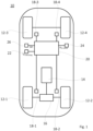
- FIG. 12 shows a motor vehicle denoted overall by the reference number 10 in a schematic representation.
- the rear wheels 12-1 and 12-2 are driven by an electric motor 14, the wheels 12-3 and 12-4 of the front axle are not driven.
- an axle differential designated by the reference number 16 is arranged in a known manner.
- each wheel 12-1, 12-2, 12-3, 12-4 of motor vehicle 10 is assigned a wheel speed sensor 18-1, 18-2, 18-3 and 18-4 in order to determine which wheel is how far in the slip is located. Control is based on this information, ie the wheel that is slipping is usually braked.
- a regulation/control unit 20 is provided which, in addition to the output signals of the wheel speed sensors 18-1, 18-2, 18-3 and 18-4, also has the current vehicle speed V vehicle as input variables, see reference number 22, the speed n of the electric motor of the electric motor 20, see reference number 24, and the speed difference ⁇ n between the wheels 12-1, 12-2 of the rear axle caused by the axle differential 16, see reference number 26.
- a comparison of the determined wheel speeds of the left rear wheel 12-1 is carried out in the control unit 14 to determine replacement wheel slip information, ie the determined theoretical wheel speed n wheel,left,theo is compared with the determined theoretical actual -Wheel speed n wheel , left, is compared.
- the comparison has shown that for wheel 12-1 the actual wheel speed n wheel,left,actual is greater by a factor of 2 and is therefore significantly greater than the theoretical wheel speed n wheel,left,theo .
- the method according to the invention makes it possible for replacement slip information to be generated, in particular even after the failure of a wheel speed sensor.
Landscapes
- Engineering & Computer Science (AREA)
- Transportation (AREA)
- Mechanical Engineering (AREA)
- Sustainable Energy (AREA)
- Power Engineering (AREA)
- Life Sciences & Earth Sciences (AREA)
- Sustainable Development (AREA)
- Chemical & Material Sciences (AREA)
- Combustion & Propulsion (AREA)
- Microelectronics & Electronic Packaging (AREA)
- Physics & Mathematics (AREA)
- Fluid Mechanics (AREA)
- Electric Propulsion And Braking For Vehicles (AREA)
- Control Of Vehicle Engines Or Engines For Specific Uses (AREA)
- Regulating Braking Force (AREA)
Description
- Die Erfindung betrifft ein Verfahren zur Bestimmung einer Radschlupfinformation eines elektrisch angetriebenen Rades eines Kraftfahrzeugs, insbesondere nach einem Ausfall eines dem Rad zugeordneten Raddrehzahlsensors, gemäß der im Patentanspruch 1 und 2 angegebenen Art.
- Um die Fahrzeugstabilität bzw. Lenkbarkeit des Kraftfahrzeugs auch auf rutschigen Untergründen zu gewährleisten, sind Informationen bzgl. des Schlupfes am Rad notwendig. Heutige ABS/ESC-Systeme nutzen Raddrehzahlinformationen um festzustellen, welches Rad sich wie weit im Schlupf befindet.
- Fällt ein oder mehrere Raddrehzahlsensoren aus, so wird dies heute dem Fahrer angezeigt (Bewarnung durch ABS/ESC-Lampe) und dem Fahrer die Verantwortung übertragen das Fahrzeug sicher zu führen oder abzustellen. Insbesondere im Hinblick auf die Funktion eines pilotierten bzw. (teil)autonomen Fahrens, hätte das zur Konsequenz, dass die Funktion des pilotierten bzw. (teil)autonomen Fahrens kurzfristig deaktiviert werden müsste, da aufgrund der fehlenden Information über den Radschlupf das Fahrzeug in eine sicherheitskritische Fahrsituation geraten könnte, die vom System nicht mehr beherrscht werden könnte.
- Ein gattungsgemäßes, sämtliche Merkmale des Oberbegriffs des Patentanspruches 1 aufweisendes Verfahren zur Bestimmung einer Radschlupfinformation eines elektrisch angetriebenen Rades eines Kraftfahrzeugs, ist aus der
US 2017/0247035 A1 bekannt. Ein ähnliches Verfahren wird zudem noch in derEP 3 020 598 A1 beschrieben - Der Erfindung liegt die Aufgabe zu Grunde ein Verfahren anzugeben, mittels dem im Falle eines Ausfalls eines Raddrehzahlsensors eine Ersatzinformation über die Haftungssituation (Schlupf) der Räder des Kraftfahrzeugs generiert werden kann.
- Diese Aufgabe wird durch die Merkmale der Patentansprüche 1 und 2 gelöst.
- Die Unteransprüche 2 bis 6 bilden vorteilhafte Weiterbildungen des erfindungsmäßen Verfahrens.
- Gemäß dem Verfahren zur Bestimmung einer Radschlupfinformation eines elektrisch angetriebenen Rades eines Kraftfahrzeugs wird die während der Fahrt des Kraftfahrzeugs erfasste Drehzahl des Elektromotors für die Bestimmung der Raddrehzahl verwendet.
- Durch das Verfahren ist nunmehr in vorteilhafter Weise gewährleistet, dass auch im Falle eines Ausfalls eines Raddrehzahlsensors eine Ersatz-Schlupf-Information generiert werden kann. D. h. es wird mittels des erfindungsgemäßen Verfahrens eine redundante Radschlupfinformation zur Verfügung gestellt. Das hat den positiven Effekt, dass - da nunmehr eine Ersatz-Schlupf-Information zur Verfügung steht - im Falle eines pilotierten bzw. (teil)autonomen Fahrens eine Deaktivierung nicht zwingend erforderlich ist.
- Gemäß Patentanspruch 1 ist dabei jedem Rad des Kraftfahrzeugs ein Elektromotor zugeordnet, d. h. jedes Rad des Kraftfahrzeugs wird über einen separaten Elektromotor angetrieben. In diesem Fall ist nach dem erfindungsgemäßen Verfahren vorgesehen, dass zur Bestimmung bzw. Generierung der Ersatz-Radschlupf-Information aus der während der Fahrt erfassten Drehzahl des Elektromotors nE-Motor sowie - sofern zwischen der Abtriebswelle des Elektromotors und der Antriebswelle des Rades ein Getriebe angeordnet ist - der Getriebeübersetzung iG eine theoretische Raddrehzahl nRad,theo des Rades gemäß der Vorschrift


- Gemäß Patentanspruch 2 werden die Räder einer Achse über einen gemeinsamen Elektromotor angetrieben und zwischen den Rädern der Achse ist ein Achsdifferential angeordnet. Die Übersetzung des Achsdifferentials ist nachfolgende als iA bezeichnet. Gegebenenfalls kann zudem zwischen der Abtriebswelle des Elektromotors und Eingangswelle zum Achsdifferential ein Getriebe mit der Getriebeübersetzung iG angeordnet sein (sofern kein Getriebe => iG=1). Verfahrensgemäß ist in diesem Fall vorgesehen, dass zur Bestimmung bzw. Generierung der Ersatz-Radschlupf-Information während der Fahrt des Kraftfahrzeugs neben der Drehzahl des Elektromotors ne-motor auch eine aus dem Achsdifferential bedingte Drehzahldifferenz Δn zwischen den Rädern der Achse erfasst wird, und dass aus der erfassten Drehzahl nE-motor des Elektromotors, der erfassten Drehzahldifferenz Δn sowie der Achsdifferentialübersetzung iA und - sofern ein Getriebe vorhanden ist - der Getriebeübersetzung iG für beide Räder der Achse eine theoretische Raddrehzahl nRad,theo gemäß der Vorschrift


- Die Erfassung der Drehzahldifferenz Δn zwischen den Rädern einer Achse kann auf verschiedene Arten erfolgen, z. B. durch einen separaten, hierzu speziell vorgesehenen Sensor. Alternativ ist es auch möglich die Drehzahldifferenz Δn anhand einer sonstigen, noch vorhandenen weiteren Stützinformation zu berechnen, z. B. in der Gestalt, dass - da in der Regel die Raddrehzahlsensoren der Räder einer Achse nicht gleichzeitig ausfallen und damit an der Achse eine Referenzinformation zu Verfügung steht - aus der Drehzahl der Eingangswelle zum Achsdifferential und der Stützinformation des nicht ausgefallen Raddrehzahlsensors die Drehzahldifferenz Δn bestimmt wird.
- Vorzugsweise werden bei beiden geschilderten Ausführungsformen zudem noch die ermittelten theoretischen Raddrehzahlen der Räder einer Achse miteinander verglichen. Ergibt z. B. der Vergleich für die Räder einer Achse, dass nRad,links,theo > nRad,rechts,theo , so ist das ein Indiz, dass im Falle einer Beschleunigung oder Fahrt mit konstanter Geschwindigkeit, das linke Rad sich im Schlupf befindet und abgebremst werden muss bzw. im Falle einer Verzögerung, d. h. einer aktiven Bremsung oder Motorschub-Rekuperation, dass das rechte Rad blockiert und der Druck aus der Bremse genommen werden muss bzw. der Motorschub/die Rekuperation zurückgenommen werden muss.
- Bevorzugt wird die Drehzahl des Elektromotors aus dem Stromverlauf, und/oder Spannungsabfall und/oder aus Informationen der Motoransteuerung bestimmt. Eine alternative Ausführungsform sieht vor, dass die Drehzahl des Elektromotors über einen Sensor, z. B. in Form eines Hall-Sensors, bestimmt wird.
- Gemäß einer weiteren vorteilhaften Ausführungsform des erfindungsgemäßen Verfahrens liegt eine signifikante Abweichung der ermittelten theoretischen Raddrehzahl nRad,theo von der ermittelten Ist-Raddrehzahl nRad,Ist vor, wenn für die Raddrehzahlen gilt:

- Eine Vorrichtung zur Durchführung des erfindungsgemäßen Verfahrens zur Bestimmung einer Radschlupfinformation eines elektrisch angetriebenen Rades eines Kraftfahrzeugs umfasst einen Elektromotor zum Antrieb des Rades, einen dem Rad zugeordneten Raddrehzahlsensor sowie Mittel zur Erfassung der Drehzahl des Elektromotors. Weiterhin umfasst die Vorrichtung eine Regel-/Steuereinheit, der als Eingangssignale die aktuelle Kraftfahrzeuggeschwindigkeit sowie die Ausgangsignale des dem Rad zugeordneten Raddrehzahlsensors zur Verfügung gestellt werden. Erfindungsgemäß werden der Regel/Steuereinheit als weitere Eingangsgröße noch die erfassten Daten über die Drehzahl des Elektromotors zur Verfügung gestellt.
- Aufgrund der nunmehr der Regel-Steuereinheit als weitere Eingangsgröße zur Verfügung gestellten Information über die Drehzahl des Elektromotors, ist die Bestimmung einer redundanten Radschlupfinformation ermöglicht.
- Vorzugsweise sind die Mittel zur Erfassung der Drehzahl des Elektromotors derart ausgebildet, dass diese die Drehzahl des Elektromotors aus dem Stromverlauf, und/oder Spannungsabfall und/oder aus Informationen der Motoransteuerung generieren.
- Eine alternative Ausgestaltung sieht vor, dass die Mittel zur Erfassung der Drehzahl des Elektromotors in Form eines separaten Sensors ausgebildet sind.
- Weitere Vorteile und Anwendungsmöglichkeiten der vorliegenden Erfindung ergeben sich aus der nachfolgenden Beschreibung in Verbindung mit dem in der Zeichnung dargestellten Ausführungsbeispiel.
- In der Zeichnung bedeutet:
- Fig. 1
- eine schematische Darstellung eines Kraftfahrzeugs zur Verdeutlichung des Verfahrens zur Bestimmung einer redundanten Radschlupfinformation eines elektrisch angetriebenen Rades eines Kraftfahrzeugs.
-
Fig. 1 zeigt in einer schematischen Darstellung ein insgesamt mit der Bezugsziffer 10 bezeichnetes Kraftfahrzeug. Vorliegend sind die hinteren Räder 12-1 und 12-2 mittels eines Elektromotors 14 angetrieben, die Räder 12-3 und 12-4 der Vorderachse sind nicht angetrieben. Zwischen den Rädern 12-1, 12-2 der Hinterachse ist in bekannter Art und Weise ein mit der Bezugsziffer 16 bezeichnetes Achsdifferential angeordnet. Zudem ist jedem Rad 12-1, 12-2, 12-3, 12-4 des Kraftfahrzeugs 10 ein Raddrehzahlsensor 18-1, 18-2, 18-3 und 18-4 zugeordnet, um festzustellen, welches Rad sich wie weit im Schlupf befindet. Auf Grundlage dieser Information wird geregelt, d. h. das Rad, welches sich im Schlupf befindet wird i. d. R. abgebremst. - Fällt nun z. B. der Radrehzahlsensor 18-1 aus, so hat dies zur Folge, dass am Rad 12-1 eine Schlupfregelung nicht mehr möglich ist. Insbesondere im Hinblick auf zukünftige Funktionen, wie z. B. pilotiertes bzw. (teil)autonomes Fahren, hätte das zur Konsequenz, dass derartige Funktionen zumindest kurzfristig deaktiviert müssten, da aufgrund des Ausfalls des Raddrehzahlsensors 18-1 am Rad 12-1 eine Schlupfregelung nicht mehr möglich ist, und somit das Kraftfahrzeug 10 in eine sicherheitskritische Fahrsituation geraten könnte.
- Genau hier setzt nun die Erfindung ein: Wie
Fig. 1 zeigt, ist eine Regel- /Steuereinheit 20 vorgesehen, der als Eingangsgrößen neben den Ausgangssignalen der Raddrehzahlsensoren 18-1, 18-2, 18-3 und 18-4, auch noch - wie schematisch angedeutet - die aktuelle Fahrzeuggeschwindigkeit VFahrzeug vgl. Bezugsziffer 22, die Drehzahl nE-Motor der Elektromotors 20, vgl. Bezugsziffer 24, als auch die aus dem Achsdifferential 16 bedingte Drehzahldifferenz Δn zwischen den Rädern 12-1, 12-2 der Hinterachse, vgl. Bezugsziffer 26, zur Verfügung gestellt werden. - Für die nachfolgende Erläuterung des Verfahrens wird angenommen, dass der dem linken Hinterrad 12-1 zugeordnete Raddrehzahlsensor 18-1 ausgefallen ist.
- In einem ersten Verfahrensschritt wird nunmehr von der Regel-Steuereinheit 14 die aufgrund der Leistungsabgabe vom Elektromotor 16 bedingte theoretische Raddrehzahl nRad,links,theo des linken Hinterrades 12-1 berechnet:

- In einem zweiten Schritt wird in der Regel-/Steuereinheit 14 aus der Fahrzeuggeschwindigkeit VFahrzeug die theoretische Ist-Raddrehzahl nRad,links,Ist des linken Hinterrads 12-1 bestimmt:

- In einem dritten Schritt wird nun zur Ermittlung einer Ersatz-Radschlupf-Information in der Regel-Steuereinheit 14 ein Vergleich der ermittelten Raddrehzahlen des linken Hinterrades 12-1 durchgeführt, d. h. die ermittelte theoretische Raddrehzahl nRad,links,theo wird mit der ermittelten theoretischen Ist-Raddrehzahl nRad,links,Ist verglichen.
- Vorliegend hat der Vergleich ergeben, dass für das Rad 12-1 die Ist-Raddrehzahl nRad,links,Ist um einen Faktor 2 und damit signifikant größer als die theoretischen Raddrehzahl nRad,links,theo ist.
- Aufgrund der festgestellten, signifikant erhöhten Ist-Raddrehzahl nRad,links,Ist des linken Hinterrads 12-1 wird nun als Ersatz-Schlupf-Information bestimmt, dass das Rad 12-1 durchdreht und sich damit im Schlupf befindet, mit der Konsequenz, dass die Regel-/Steuereinheit eine Schlupfregelung veranlasst, indem das betroffene Rad 12-1 abgebremst wird.
- Somit wird, wie dargelegt, durch das erfindungsgemäße Verfahren ermöglicht, dass insbesondere auch nach Ausfall eines Raddrehzahlsensors eine Ersatz-Schlupf-Information generiert werden kann.
Claims (6)
- Verfahren zur Bestimmung einer Radschlupfinformation eines elektrisch angetriebenen Rades (12-1, 12-2, 12-3, 12-4) eines Kraftfahrzeugs (10), gemäß dem während der Fahrt die Drehzahl (nE-motor) eines das Rad (12-1, 12-2, 12-3, 12-4) antreibenden Elektromotors (16) erfasst wird und die erfasste Drehzahl (nE-motor) des Elektromotors (16) für die Bestimmung der Radschlupfinformation verwendet wird, dadurch gekennzeichnet, dass
jedem elektrisch angetriebenen Rad (12-1, 12-2, 12-3, 12-4) ein separater Elektromotor (14) zugeordnet ist, wobei aus der erfassten Drehzahl (nE-motor) des Elektromotors (14) und Getriebeübersetzung (iG) eine theoretische Raddrehzahl (nRad,theo) des Rades (12-1, 12-2, 12-3, 12-4) bestimmt wird, und wobei aus der aktuellen Fahrgeschwindigkeit (VFahrzeug) des Kraftfahrzeugs (10) eine Ist-Raddrehzahl (nRad,Ist) des Rades (12-1, 12-2, 12-3, 12-4) bestimmt wird, wobei im Falle, dass die theoretische Raddrehzahl (nRad,theo) des Rades (12-1, 12-2, 12-3, 12-4) von der Ist-Raddrehzahl (nRad,Ist) des Rades (12-1, 12-2, 12-3, 12-4) abweicht als Radschlupfinformation bestimmt wird, dass das Rad (12-1, 12-2, 12-3, 12-4) sich im Schlupf befindet. - Verfahren zur Bestimmung einer Radschlupfinformation eines elektrisch angetriebenen Rades (12-1, 12-2, 12-3, 12-4) eines Kraftfahrzeugs (10), gemäß dem während der Fahrt die Drehzahl (nE -motor) eines das Rad (12-1, 12-2, 12-3, 12-4) antreibenden Elektromotors (16) erfasst wird und die erfasste Drehzahl (nE -motor) des Elektromotors (16) für die Bestimmung der Radschlupfinformation verwendet wird,
dadurch gekennzeichnet, dassdie Räder (12-1, 12,2, 12-3, 12-4) einer Achse über einen gemeinsamen Elektromotor (14) und ein Achsdifferential (16) angetrieben werden und eine aus dem Achsdifferential (16) bedingte Drehzahldifferenz (Δn) zwischen den Rädern (12-1, 12,2, 12-3, 12-4) der Achse erfasst wird, wobei aus der erfassten Drehzahl (nE-motor) des Elektromotors (16), der Drehzahldifferenz (Δn) sowie der Getriebe- und Achsdifferentialübersetzung (iG ,iA) für beide Räder (12-1, 12,2, 12-3, 12-4) der Achse eine theoretische Raddrehzahl (nRad,theo) bestimmt wird, und wobei aus der aktuellen Fahrgeschwindigkeit (VFahr-zeug) des Kraftfahrzeugs (10) eine Ist-Raddrehzahl (nRad,Ist) der Räder (12-1, 12,2, 12-3, 12-4) der Achse bestimmt wird, wobei im Falle das die theoretische Radrehzahl (nRad,theo) eines oder beider Räder (12-1, 12,2 / 12-3, 12-4) von der Ist-Raddrehzahl (nRad,Ist) abweicht als Radschlupfinformation bestimmt, dass das betroffene Rad oder beide Räder (12-1, 12,2 / 12-3, 12-4) der Achse sich im Schlupf befinden, wobei die theoretische Raddrehzahl (nRad,theo) der Räder (12-1, 12,2, 12-3, 12-4) der Achse gemäß der Vorschrift die Ist-Raddrehzahl (nRad,Ist) der Räder (12-1, 12,2, 12-3, 12-4) der Achse gemäß der Vorschrift
 berechnet wird.
 - Verfahren nach Anspruch 1 oder 2,
dadurch gekennzeichnet, dass
die Drehzahl (nE-motor) des Elektromotors (14) aus dem Stromverlauf, und/oder Spannungsabfall und/oder aus Informationen der Motoransteuerung bestimmt wird. - Verfahren nach Anspruche 1 oder 2,
dadurch gekennzeichnet, dass
die Drehzahl (nE-motor) des Elektromotors (14) über einen Sensor bestimmt wird. - Verfahren nach Anspruch 1,
dadurch gekennzeichnet, dassdie theoretische Raddrehzahl (nRad,theo) des Rades (12-1, 12,2, 12-3, 12-4) gemäß der Vorschrift die Ist-Raddrehzahl (nRad,Ist) des Rades (12-1, 12,2 / 12-3, 12-4) gemäß der Vorschrift
 berechnet wird.
 - Verfahren nach Anspruch 1 oder 2,
dadurch gekennzeichnet, dass
eine Abweichung der Ist-Raddrehzahl (nRad,Ist) von der theoretischen Raddrehzahl vorliegt, wenn für Raddrehzahlen gilt:
Applications Claiming Priority (2)
| Application Number | Priority Date | Filing Date | Title |
|---|---|---|---|
| DE102017216020.9A DE102017216020A1 (de) | 2017-09-12 | 2017-09-12 | Verfahren und Vorrichtung zur Bestimmung einer Radschlupfinformation eines elektrisch angetriebenen Rades eines Kraftfahrzeugs |
| PCT/EP2018/073139 WO2019052807A1 (de) | 2017-09-12 | 2018-08-28 | Verfahren und vorrichtung zur bestimmung einer radschlupfinformation eines elektrisch angetriebenen rades eines kraftfahrzeugs |
Publications (2)
| Publication Number | Publication Date |
|---|---|
| EP3681749A1 EP3681749A1 (de) | 2020-07-22 |
| EP3681749B1 true EP3681749B1 (de) | 2023-03-08 |
Family
ID=63528712
Family Applications (1)
| Application Number | Title | Priority Date | Filing Date |
|---|---|---|---|
| EP18766148.3A Active EP3681749B1 (de) | 2017-09-12 | 2018-08-28 | Verfahren und vorrichtung zur bestimmung einer radschlupfinformation eines elektrisch angetriebenen rades eines kraftfahrzeugs |
Country Status (5)
| Country | Link |
|---|---|
| US (1) | US11584234B2 (de) |
| EP (1) | EP3681749B1 (de) |
| CN (1) | CN110997383B (de) |
| DE (1) | DE102017216020A1 (de) |
| WO (1) | WO2019052807A1 (de) |
Families Citing this family (7)
| Publication number | Priority date | Publication date | Assignee | Title |
|---|---|---|---|---|
| JP7349271B2 (ja) * | 2019-06-20 | 2023-09-22 | 株式会社日立製作所 | 列車保安システム、列車保安制御方法及び列車車上装置 |
| CN110550047A (zh) * | 2019-09-29 | 2019-12-10 | 潍柴西港新能源动力有限公司 | 一种车速信号可信性检测的方法及系统 |
| EP4005883B1 (de) * | 2020-11-25 | 2025-11-26 | Volvo Truck Corporation | System und verfahren zur steuerung des radschlupfes eines fahrzeugs |
| CN112659900A (zh) * | 2020-12-23 | 2021-04-16 | 宝能(广州)汽车研究院有限公司 | 驱动防滑控制方法与装置、存储介质、车辆 |
| US20240124000A1 (en) * | 2022-10-18 | 2024-04-18 | Robert Bosch Gmbh | Detection and compensation of wheel speed sensor failure |
| JP7754081B2 (ja) * | 2022-12-27 | 2025-10-15 | トヨタ自動車株式会社 | 車両用走行制御装置 |
| DE102024205956A1 (de) * | 2024-06-26 | 2025-12-31 | Volkswagen Aktiengesellschaft | Verfahren zum Ermitteln einer Raddrehzahl eines Rades eines Kraftfahrzeugs |
Family Cites Families (22)
| Publication number | Priority date | Publication date | Assignee | Title |
|---|---|---|---|---|
| DE4017891C1 (de) * | 1990-06-02 | 1991-09-05 | Mercedes-Benz Aktiengesellschaft, 7000 Stuttgart, De | |
| DE4402699C2 (de) | 1994-01-29 | 1996-01-11 | Continental Ag | Vorrichtung zur Verminderung des Reifen/Fahrbahngeräusches |
| US5574643A (en) * | 1994-07-15 | 1996-11-12 | Caterpillar Inc. | Traction control for a machine with electronic engine and transmission controls |
| EP1759915A3 (de) | 1998-07-21 | 2007-03-14 | TOKYO R&D CO., LTD. | Hybridfahrzeug und Verfahren zur Fahrzeugfahrtregelung |
| US7957881B2 (en) * | 2006-10-04 | 2011-06-07 | Toyota Jidosha Kabushiki Kaisha | Vehicle and method of controlling driving force for the vehicle based on detected slip of the drive wheel |
| DE102008011791B4 (de) | 2008-02-29 | 2013-09-19 | Airbus Operations Gmbh | Integriertes multifunktionales Radantriebssystem für Luftfahrzeuge |
| JP4873499B2 (ja) * | 2008-08-07 | 2012-02-08 | 日本輸送機株式会社 | リーチ型フォークリフトにおける駆動輪のトラクション制御方法およびそのシステム |
| JP4751455B2 (ja) * | 2009-01-27 | 2011-08-17 | 本田技研工業株式会社 | 車両の駆動力制御装置 |
| DE102010003076A1 (de) * | 2009-08-05 | 2011-08-18 | Continental Automotive GmbH, 30165 | Verfahren zur Regelung eines Radbremsschlupfes und Radbremsschlupfregelsystem für ein Fahrzeug mit einem Elektroantrieb |
| DE102010018705A1 (de) * | 2010-04-29 | 2011-11-03 | Dr. Ing. H.C. F. Porsche Aktiengesellschaft | Verfahren zur Einstellung des Betriebsverhaltens des Antriebsstrangs eines Kraftfahrzeugs |
| US8521468B2 (en) | 2010-08-25 | 2013-08-27 | GM Global Technology Operations LLC | Diagnostic method for use with a vehicle dynamic control system (VDCS) |
| JP5336447B2 (ja) | 2010-09-02 | 2013-11-06 | 日立建機株式会社 | 電気駆動車両 |
| DE102010062646A1 (de) * | 2010-12-08 | 2012-06-14 | Robert Bosch Gmbh | Verfahren zur Drehzahlbestimmung und Antriebseinheit |
| DE102011100811B4 (de) * | 2011-05-06 | 2021-09-16 | Audi Ag | Antiblockiersystem für ein Fahrzeug mit elektromotorischem Fahrzeugantrieb |
| EP2540544B1 (de) | 2011-06-28 | 2014-02-26 | Siemens Aktiengesellschaft | Drehmomentüberwachung bei Fahrzeugen |
| KR101219350B1 (ko) * | 2011-09-20 | 2013-01-21 | 현대자동차주식회사 | 차량의 인휠 모터를 이용한 휠속 감지 장치 및 이의 제어 방법 |
| CN102501779B (zh) | 2011-10-31 | 2013-12-11 | 长城汽车股份有限公司 | 一种电动汽车牵引力控制方法 |
| JP6342188B2 (ja) * | 2013-07-08 | 2018-06-13 | Ntn株式会社 | 電気自動車のスリップ制御装置 |
| JP2015119525A (ja) * | 2013-12-17 | 2015-06-25 | Ntn株式会社 | 電動車両の異常検知装置 |
| JP6490246B2 (ja) * | 2016-01-13 | 2019-03-27 | 三菱電機株式会社 | 電気車制御装置 |
| JP6335955B2 (ja) * | 2016-02-29 | 2018-05-30 | 株式会社Subaru | 車両の制御装置及び車両の制御方法 |
| CN105751919B (zh) | 2016-03-31 | 2018-06-12 | 电子科技大学 | 一种四轮轮毂电动汽车防滑控制方法 |
-
2017
- 2017-09-12 DE DE102017216020.9A patent/DE102017216020A1/de not_active Withdrawn
-
2018
- 2018-08-28 CN CN201880053185.9A patent/CN110997383B/zh active Active
- 2018-08-28 US US16/633,704 patent/US11584234B2/en active Active
- 2018-08-28 WO PCT/EP2018/073139 patent/WO2019052807A1/de not_active Ceased
- 2018-08-28 EP EP18766148.3A patent/EP3681749B1/de active Active
Also Published As
| Publication number | Publication date |
|---|---|
| CN110997383B (zh) | 2024-02-13 |
| CN110997383A (zh) | 2020-04-10 |
| DE102017216020A1 (de) | 2019-03-14 |
| EP3681749A1 (de) | 2020-07-22 |
| US11584234B2 (en) | 2023-02-21 |
| WO2019052807A1 (de) | 2019-03-21 |
| US20200198471A1 (en) | 2020-06-25 |
Similar Documents
| Publication | Publication Date | Title |
|---|---|---|
| EP3681749B1 (de) | Verfahren und vorrichtung zur bestimmung einer radschlupfinformation eines elektrisch angetriebenen rades eines kraftfahrzeugs | |
| DE102009019365B4 (de) | System und Verfahren zum Zusammenschließen eines Torque-Vectoring-Differentials mit einem Stabilitätssteuerungssystem | |
| WO2012100871A1 (de) | Verfahren zur erkennung und korrektur der fahrzeugreferenzgeschwindigkeit und fahrzeugsystem | |
| EP2487079B1 (de) | Verfahren zum Betreiben eines Kraftfahrzeugs bei Durchfahren einer Kurve | |
| DE102018205904B4 (de) | Verfahren zum Bestimmen zumindest eines Reibwerts, Vorrichtung | |
| DE102017000954A1 (de) | System, Verfahren, Computerprogramm und Steuergerät zum Verhindern eines Wegrollens eines Fahrzeugs | |
| DE19722116A1 (de) | Antiblockierbremssteuersystem für Kraftfahrzeuge und zugehöriges Bremskraftsteuerverfahren | |
| DE102007045998A1 (de) | Technik zur Verbesserung der Fahrstabilität eines Kraftfahrzeugs auf Basis einer Massebestimmung | |
| DE102018200180A1 (de) | Verfahren zur Ermittlung des Reibwerts zwischen einem Fahrzeugrad und der Fahrbahn | |
| EP3496970B1 (de) | Verfahren und vorrichtung zum betreiben eines kraftfahrzeugs, kraftfahrzeug | |
| DE69715134T2 (de) | Verfahren und Ausrüstung zum Erkennen eines Reifens mit zumindest teilweisem Druckverlust an einem Kraftfahtzeug. | |
| DE102019000846A1 (de) | Verfahren zur Überwachung einer Antriebsschlupfregelung eines Kraftfahrzeugs, entsprechendes Kraftfahrzeug sowie Regler | |
| DE102019218151A1 (de) | Verfahren zum Betreiben einer automatisierten Feststellbremse | |
| DE102022204291A1 (de) | Verfahren zum Betreiben eines Steer-by-Wire-Lenksystems und Steer-by-Wire-Lenksystem | |
| WO2014040781A1 (de) | Verfahren zum betrieb eines elektromotorisch angetriebenen fahrzeugs | |
| DE102007046692B4 (de) | Antiblockiersystem für ein Kraftfahrzeug | |
| WO2020074259A1 (de) | Verfahren zur verteilung eines von einem fahrer angeforderten bremsmoments auf die achsen eines kraftfahrzeugs | |
| DE102019000615A1 (de) | Fahrzeug | |
| DE102010021352B4 (de) | Antriebsvorrichtung für ein Kraftfahrzeug | |
| DE102008020410A1 (de) | Kurven-Spurassistent bei Beschleunigung | |
| DE102015207293A1 (de) | Verfahren zur Regelung von Schaltvorgängen in einem Kraftfahrzeuggetriebe eines Kraftfahrzeuges | |
| DE19617051A1 (de) | Verfahren zur Beeinflussung fahrdynamischer Größen | |
| DE102021134307A1 (de) | Vorrichtung und verfahren zur steuerung einer elektromechanischen bremse | |
| EP1152938A1 (de) | Verfahren und vorrichtung zur einstellung der brems- und/oder antriebswirkung an den rädern eines kraftfahrzeugs | |
| WO2013072100A1 (de) | Bremssystem für ein fahrzeug, verfahren zum betreiben eines bremssystems |
Legal Events
| Date | Code | Title | Description |
|---|---|---|---|
| STAA | Information on the status of an ep patent application or granted ep patent |
Free format text: STATUS: UNKNOWN |
|
| STAA | Information on the status of an ep patent application or granted ep patent |
Free format text: STATUS: THE INTERNATIONAL PUBLICATION HAS BEEN MADE |
|
| PUAI | Public reference made under article 153(3) epc to a published international application that has entered the european phase |
Free format text: ORIGINAL CODE: 0009012 |
|
| STAA | Information on the status of an ep patent application or granted ep patent |
Free format text: STATUS: REQUEST FOR EXAMINATION WAS MADE |
|
| 17P | Request for examination filed |
Effective date: 20200414 |
|
| AK | Designated contracting states |
Kind code of ref document: A1 Designated state(s): AL AT BE BG CH CY CZ DE DK EE ES FI FR GB GR HR HU IE IS IT LI LT LU LV MC MK MT NL NO PL PT RO RS SE SI SK SM TR |
|
| AX | Request for extension of the european patent |
Extension state: BA ME |
|
| DAV | Request for validation of the european patent (deleted) | ||
| DAX | Request for extension of the european patent (deleted) | ||
| GRAP | Despatch of communication of intention to grant a patent |
Free format text: ORIGINAL CODE: EPIDOSNIGR1 |
|
| STAA | Information on the status of an ep patent application or granted ep patent |
Free format text: STATUS: GRANT OF PATENT IS INTENDED |
|
| INTG | Intention to grant announced |
Effective date: 20221213 |
|
| GRAS | Grant fee paid |
Free format text: ORIGINAL CODE: EPIDOSNIGR3 |
|
| GRAA | (expected) grant |
Free format text: ORIGINAL CODE: 0009210 |
|
| STAA | Information on the status of an ep patent application or granted ep patent |
Free format text: STATUS: THE PATENT HAS BEEN GRANTED |
|
| AK | Designated contracting states |
Kind code of ref document: B1 Designated state(s): AL AT BE BG CH CY CZ DE DK EE ES FI FR GB GR HR HU IE IS IT LI LT LU LV MC MK MT NL NO PL PT RO RS SE SI SK SM TR |
|
| REG | Reference to a national code |
Ref country code: CH Ref legal event code: EP Ref country code: AT Ref legal event code: REF Ref document number: 1552360 Country of ref document: AT Kind code of ref document: T Effective date: 20230315 |
|
| REG | Reference to a national code |
Ref country code: DE Ref legal event code: R096 Ref document number: 502018011737 Country of ref document: DE |
|
| REG | Reference to a national code |
Ref country code: IE Ref legal event code: FG4D Free format text: LANGUAGE OF EP DOCUMENT: GERMAN |
|
| REG | Reference to a national code |
Ref country code: LT Ref legal event code: MG9D |
|
| P01 | Opt-out of the competence of the unified patent court (upc) registered |
Effective date: 20230530 |
|
| REG | Reference to a national code |
Ref country code: NL Ref legal event code: MP Effective date: 20230308 |
|
| PG25 | Lapsed in a contracting state [announced via postgrant information from national office to epo] |
Ref country code: RS Free format text: LAPSE BECAUSE OF FAILURE TO SUBMIT A TRANSLATION OF THE DESCRIPTION OR TO PAY THE FEE WITHIN THE PRESCRIBED TIME-LIMIT Effective date: 20230308 Ref country code: NO Free format text: LAPSE BECAUSE OF FAILURE TO SUBMIT A TRANSLATION OF THE DESCRIPTION OR TO PAY THE FEE WITHIN THE PRESCRIBED TIME-LIMIT Effective date: 20230608 Ref country code: LV Free format text: LAPSE BECAUSE OF FAILURE TO SUBMIT A TRANSLATION OF THE DESCRIPTION OR TO PAY THE FEE WITHIN THE PRESCRIBED TIME-LIMIT Effective date: 20230308 Ref country code: LT Free format text: LAPSE BECAUSE OF FAILURE TO SUBMIT A TRANSLATION OF THE DESCRIPTION OR TO PAY THE FEE WITHIN THE PRESCRIBED TIME-LIMIT Effective date: 20230308 Ref country code: HR Free format text: LAPSE BECAUSE OF FAILURE TO SUBMIT A TRANSLATION OF THE DESCRIPTION OR TO PAY THE FEE WITHIN THE PRESCRIBED TIME-LIMIT Effective date: 20230308 Ref country code: ES Free format text: LAPSE BECAUSE OF FAILURE TO SUBMIT A TRANSLATION OF THE DESCRIPTION OR TO PAY THE FEE WITHIN THE PRESCRIBED TIME-LIMIT Effective date: 20230308 |
|
| PG25 | Lapsed in a contracting state [announced via postgrant information from national office to epo] |
Ref country code: SE Free format text: LAPSE BECAUSE OF FAILURE TO SUBMIT A TRANSLATION OF THE DESCRIPTION OR TO PAY THE FEE WITHIN THE PRESCRIBED TIME-LIMIT Effective date: 20230308 Ref country code: NL Free format text: LAPSE BECAUSE OF FAILURE TO SUBMIT A TRANSLATION OF THE DESCRIPTION OR TO PAY THE FEE WITHIN THE PRESCRIBED TIME-LIMIT Effective date: 20230308 Ref country code: GR Free format text: LAPSE BECAUSE OF FAILURE TO SUBMIT A TRANSLATION OF THE DESCRIPTION OR TO PAY THE FEE WITHIN THE PRESCRIBED TIME-LIMIT Effective date: 20230609 Ref country code: FI Free format text: LAPSE BECAUSE OF FAILURE TO SUBMIT A TRANSLATION OF THE DESCRIPTION OR TO PAY THE FEE WITHIN THE PRESCRIBED TIME-LIMIT Effective date: 20230308 |
|
| PG25 | Lapsed in a contracting state [announced via postgrant information from national office to epo] |
Ref country code: SM Free format text: LAPSE BECAUSE OF FAILURE TO SUBMIT A TRANSLATION OF THE DESCRIPTION OR TO PAY THE FEE WITHIN THE PRESCRIBED TIME-LIMIT Effective date: 20230308 Ref country code: RO Free format text: LAPSE BECAUSE OF FAILURE TO SUBMIT A TRANSLATION OF THE DESCRIPTION OR TO PAY THE FEE WITHIN THE PRESCRIBED TIME-LIMIT Effective date: 20230308 Ref country code: PT Free format text: LAPSE BECAUSE OF FAILURE TO SUBMIT A TRANSLATION OF THE DESCRIPTION OR TO PAY THE FEE WITHIN THE PRESCRIBED TIME-LIMIT Effective date: 20230710 Ref country code: EE Free format text: LAPSE BECAUSE OF FAILURE TO SUBMIT A TRANSLATION OF THE DESCRIPTION OR TO PAY THE FEE WITHIN THE PRESCRIBED TIME-LIMIT Effective date: 20230308 Ref country code: CZ Free format text: LAPSE BECAUSE OF FAILURE TO SUBMIT A TRANSLATION OF THE DESCRIPTION OR TO PAY THE FEE WITHIN THE PRESCRIBED TIME-LIMIT Effective date: 20230308 |
|
| PG25 | Lapsed in a contracting state [announced via postgrant information from national office to epo] |
Ref country code: SK Free format text: LAPSE BECAUSE OF FAILURE TO SUBMIT A TRANSLATION OF THE DESCRIPTION OR TO PAY THE FEE WITHIN THE PRESCRIBED TIME-LIMIT Effective date: 20230308 Ref country code: PL Free format text: LAPSE BECAUSE OF FAILURE TO SUBMIT A TRANSLATION OF THE DESCRIPTION OR TO PAY THE FEE WITHIN THE PRESCRIBED TIME-LIMIT Effective date: 20230308 Ref country code: IS Free format text: LAPSE BECAUSE OF FAILURE TO SUBMIT A TRANSLATION OF THE DESCRIPTION OR TO PAY THE FEE WITHIN THE PRESCRIBED TIME-LIMIT Effective date: 20230708 |
|
| REG | Reference to a national code |
Ref country code: DE Ref legal event code: R097 Ref document number: 502018011737 Country of ref document: DE |
|
| PLBE | No opposition filed within time limit |
Free format text: ORIGINAL CODE: 0009261 |
|
| STAA | Information on the status of an ep patent application or granted ep patent |
Free format text: STATUS: NO OPPOSITION FILED WITHIN TIME LIMIT |
|
| PG25 | Lapsed in a contracting state [announced via postgrant information from national office to epo] |
Ref country code: SI Free format text: LAPSE BECAUSE OF FAILURE TO SUBMIT A TRANSLATION OF THE DESCRIPTION OR TO PAY THE FEE WITHIN THE PRESCRIBED TIME-LIMIT Effective date: 20230308 Ref country code: DK Free format text: LAPSE BECAUSE OF FAILURE TO SUBMIT A TRANSLATION OF THE DESCRIPTION OR TO PAY THE FEE WITHIN THE PRESCRIBED TIME-LIMIT Effective date: 20230308 |
|
| 26N | No opposition filed |
Effective date: 20231211 |
|
| PG25 | Lapsed in a contracting state [announced via postgrant information from national office to epo] |
Ref country code: MC Free format text: LAPSE BECAUSE OF FAILURE TO SUBMIT A TRANSLATION OF THE DESCRIPTION OR TO PAY THE FEE WITHIN THE PRESCRIBED TIME-LIMIT Effective date: 20230308 |
|
| REG | Reference to a national code |
Ref country code: CH Ref legal event code: PL |
|
| PG25 | Lapsed in a contracting state [announced via postgrant information from national office to epo] |
Ref country code: MC Free format text: LAPSE BECAUSE OF FAILURE TO SUBMIT A TRANSLATION OF THE DESCRIPTION OR TO PAY THE FEE WITHIN THE PRESCRIBED TIME-LIMIT Effective date: 20230308 |
|
| PG25 | Lapsed in a contracting state [announced via postgrant information from national office to epo] |
Ref country code: LU Free format text: LAPSE BECAUSE OF NON-PAYMENT OF DUE FEES Effective date: 20230828 |
|
| PG25 | Lapsed in a contracting state [announced via postgrant information from national office to epo] |
Ref country code: LU Free format text: LAPSE BECAUSE OF NON-PAYMENT OF DUE FEES Effective date: 20230828 Ref country code: CH Free format text: LAPSE BECAUSE OF NON-PAYMENT OF DUE FEES Effective date: 20230831 |
|
| REG | Reference to a national code |
Ref country code: BE Ref legal event code: MM Effective date: 20230831 |
|
| REG | Reference to a national code |
Ref country code: IE Ref legal event code: MM4A |
|
| PG25 | Lapsed in a contracting state [announced via postgrant information from national office to epo] |
Ref country code: IT Free format text: LAPSE BECAUSE OF FAILURE TO SUBMIT A TRANSLATION OF THE DESCRIPTION OR TO PAY THE FEE WITHIN THE PRESCRIBED TIME-LIMIT Effective date: 20230308 |
|
| PG25 | Lapsed in a contracting state [announced via postgrant information from national office to epo] |
Ref country code: IE Free format text: LAPSE BECAUSE OF NON-PAYMENT OF DUE FEES Effective date: 20230828 |
|
| PG25 | Lapsed in a contracting state [announced via postgrant information from national office to epo] |
Ref country code: IE Free format text: LAPSE BECAUSE OF NON-PAYMENT OF DUE FEES Effective date: 20230828 |
|
| PG25 | Lapsed in a contracting state [announced via postgrant information from national office to epo] |
Ref country code: BE Free format text: LAPSE BECAUSE OF NON-PAYMENT OF DUE FEES Effective date: 20230831 |
|
| REG | Reference to a national code |
Ref country code: AT Ref legal event code: MM01 Ref document number: 1552360 Country of ref document: AT Kind code of ref document: T Effective date: 20230828 |
|
| PG25 | Lapsed in a contracting state [announced via postgrant information from national office to epo] |
Ref country code: AT Free format text: LAPSE BECAUSE OF NON-PAYMENT OF DUE FEES Effective date: 20230828 |
|
| PG25 | Lapsed in a contracting state [announced via postgrant information from national office to epo] |
Ref country code: AT Free format text: LAPSE BECAUSE OF NON-PAYMENT OF DUE FEES Effective date: 20230828 |
|
| PG25 | Lapsed in a contracting state [announced via postgrant information from national office to epo] |
Ref country code: BG Free format text: LAPSE BECAUSE OF FAILURE TO SUBMIT A TRANSLATION OF THE DESCRIPTION OR TO PAY THE FEE WITHIN THE PRESCRIBED TIME-LIMIT Effective date: 20230308 |
|
| PG25 | Lapsed in a contracting state [announced via postgrant information from national office to epo] |
Ref country code: BG Free format text: LAPSE BECAUSE OF FAILURE TO SUBMIT A TRANSLATION OF THE DESCRIPTION OR TO PAY THE FEE WITHIN THE PRESCRIBED TIME-LIMIT Effective date: 20230308 |
|
| PG25 | Lapsed in a contracting state [announced via postgrant information from national office to epo] |
Ref country code: CY Free format text: LAPSE BECAUSE OF FAILURE TO SUBMIT A TRANSLATION OF THE DESCRIPTION OR TO PAY THE FEE WITHIN THE PRESCRIBED TIME-LIMIT; INVALID AB INITIO Effective date: 20180828 |
|
| PG25 | Lapsed in a contracting state [announced via postgrant information from national office to epo] |
Ref country code: HU Free format text: LAPSE BECAUSE OF FAILURE TO SUBMIT A TRANSLATION OF THE DESCRIPTION OR TO PAY THE FEE WITHIN THE PRESCRIBED TIME-LIMIT; INVALID AB INITIO Effective date: 20180828 |
|
| PGFP | Annual fee paid to national office [announced via postgrant information from national office to epo] |
Ref country code: DE Payment date: 20250831 Year of fee payment: 8 |
|
| PGFP | Annual fee paid to national office [announced via postgrant information from national office to epo] |
Ref country code: GB Payment date: 20250822 Year of fee payment: 8 |
|
| PGFP | Annual fee paid to national office [announced via postgrant information from national office to epo] |
Ref country code: FR Payment date: 20250821 Year of fee payment: 8 |
|
| PG25 | Lapsed in a contracting state [announced via postgrant information from national office to epo] |
Ref country code: TR Free format text: LAPSE BECAUSE OF FAILURE TO SUBMIT A TRANSLATION OF THE DESCRIPTION OR TO PAY THE FEE WITHIN THE PRESCRIBED TIME-LIMIT Effective date: 20230308 |