EP3680513A1 - Wellenlager für wellenbewegungsgetriebe - Google Patents
Wellenlager für wellenbewegungsgetriebe Download PDFInfo
- Publication number
- EP3680513A1 EP3680513A1 EP17924333.2A EP17924333A EP3680513A1 EP 3680513 A1 EP3680513 A1 EP 3680513A1 EP 17924333 A EP17924333 A EP 17924333A EP 3680513 A1 EP3680513 A1 EP 3680513A1
- Authority
- EP
- European Patent Office
- Prior art keywords
- wave
- gear
- flexible
- toothed gear
- peripheral surface
- Prior art date
- Legal status (The legal status is an assumption and is not a legal conclusion. Google has not performed a legal analysis and makes no representation as to the accuracy of the status listed.)
- Withdrawn
Links
Images
Classifications
-
- F—MECHANICAL ENGINEERING; LIGHTING; HEATING; WEAPONS; BLASTING
- F16—ENGINEERING ELEMENTS AND UNITS; GENERAL MEASURES FOR PRODUCING AND MAINTAINING EFFECTIVE FUNCTIONING OF MACHINES OR INSTALLATIONS; THERMAL INSULATION IN GENERAL
- F16H—GEARING
- F16H49/00—Other gearings
- F16H49/001—Wave gearings, e.g. harmonic drive transmissions
-
- F—MECHANICAL ENGINEERING; LIGHTING; HEATING; WEAPONS; BLASTING
- F16—ENGINEERING ELEMENTS AND UNITS; GENERAL MEASURES FOR PRODUCING AND MAINTAINING EFFECTIVE FUNCTIONING OF MACHINES OR INSTALLATIONS; THERMAL INSULATION IN GENERAL
- F16H—GEARING
- F16H1/00—Toothed gearings for conveying rotary motion
- F16H1/28—Toothed gearings for conveying rotary motion with gears having orbital motion
- F16H1/32—Toothed gearings for conveying rotary motion with gears having orbital motion in which the central axis of the gearing lies inside the periphery of an orbital gear
-
- F—MECHANICAL ENGINEERING; LIGHTING; HEATING; WEAPONS; BLASTING
- F16—ENGINEERING ELEMENTS AND UNITS; GENERAL MEASURES FOR PRODUCING AND MAINTAINING EFFECTIVE FUNCTIONING OF MACHINES OR INSTALLATIONS; THERMAL INSULATION IN GENERAL
- F16H—GEARING
- F16H55/00—Elements with teeth or friction surfaces for conveying motion; Worms, pulleys or sheaves for gearing mechanisms
- F16H55/02—Toothed members; Worms
- F16H55/08—Profiling
-
- F—MECHANICAL ENGINEERING; LIGHTING; HEATING; WEAPONS; BLASTING
- F16—ENGINEERING ELEMENTS AND UNITS; GENERAL MEASURES FOR PRODUCING AND MAINTAINING EFFECTIVE FUNCTIONING OF MACHINES OR INSTALLATIONS; THERMAL INSULATION IN GENERAL
- F16C—SHAFTS; FLEXIBLE SHAFTS; ELEMENTS OR CRANKSHAFT MECHANISMS; ROTARY BODIES OTHER THAN GEARING ELEMENTS; BEARINGS
- F16C2361/00—Apparatus or articles in engineering in general
-
- F—MECHANICAL ENGINEERING; LIGHTING; HEATING; WEAPONS; BLASTING
- F16—ENGINEERING ELEMENTS AND UNITS; GENERAL MEASURES FOR PRODUCING AND MAINTAINING EFFECTIVE FUNCTIONING OF MACHINES OR INSTALLATIONS; THERMAL INSULATION IN GENERAL
- F16H—GEARING
- F16H49/00—Other gearings
- F16H49/001—Wave gearings, e.g. harmonic drive transmissions
- F16H2049/003—Features of the flexsplines therefor
Definitions
- the present invention relates to a strain wave gearing and, in particular, to a wave bearing of a wave generator in a strain wave gearing.
- Patent Document 1 discloses a strain wave reduction gear provided with a wave bearing composed of a ball bearing.
- Patent document 1 JP 2017-36747 A
- a wave bearing composed of a ball bearing has a retainer to hold adjacent balls at a constant interval.
- a retainer is provided with partitioning walls of a predetermined thickness arranged at constant intervals in a circumferential direction and a pocket for holding a ball is formed between each pair of adjacent partitioning walls. Accordingly, the number of balls that can be inserted between the inner and outer races is restricted by provision of the partitioning walls.
- the rated load is enhanced by reducing the distance between adjacent balls to increase the number of balls, whereby the lifetime thereof is prolonged.
- the thickness of the partitioning walls of the retainer is reduced so as to increase the number of balls.
- the number of balls is still limited by the partitioning walls of the retainer.
- An object of the present invention is to provide a strain wave gearing which can enhance reliability thereof during high load operation by increasing load capacity of a wave bearing.
- the present invention is characterized by employing, as a wave bearing of a strain wave gearing, a full complement ball bearing provided with inner and outer races flexible in a radial direction, to which attention has not been paid in the past.
- a strain wave gearing of the present invention has a rigid gear, a flexible gear, and a wave generator that makes the flexible gear to flex into a non-circular shape to partially mesh with the rigid gear and makes a meshing position of the flexible gear with respect to the rigid gear in a circumferential direction.
- the wave generator has: a rigid cam plate provided with a non-circular outer peripheral surface or a non-circular inner peripheral surface; and a wave bearing that is mounted between the non-circular outer peripheral surface and an inner peripheral surface of the flexible gear or between the non-circular inner peripheral surface and an outer peripheral surface of the flexible gear so as to support the rigid cam plate and the flexible gear in a relatively rotatable state.
- the wave bearing is a full complement ball bearing provided with inner and outer races that are flexible in a radial direction.
- the wave bearing of the strain wave gearing according to the present invention is not provided with a retainer, so that adjacent balls are in contact with each other in a ball raceway between the inner and outer races.
- the rigid cam plate and the flexible gear are relatively rotated while adjacent balls come into rolling contact with each other.
- the number of balls mounted in the ball raceway between the inner and outer races is not limited by the partitioning walls of a retainer, so that the maximum number of balls can be mounted. Therefore, it is possible to realize a wave bearing having a large load capacity, whereby enhancing the reliability of the strain wave gearing during high load operation.
- the wave bearing of the present invention is particularly suited for a strain wave gearing which is driven in a low-speed and high-load operation.
- the inner and outer races are flexed into a non-circular shape by the rigid cam plate, but the retainer remains in an annular shape.
- the inner and outer races flexed in a radial direction must be limited in an amount of flexion to prevent from interfering with the retainer.
- a rigid gear and a flexible gear both having a small number of teeth are employed, which causes the flexible gear to have an increased amount of flexion in the radial direction. Since the amount of flexion of the inner and outer races also increase, there arise a possibility that the inner and outer races interfere with the retainer.
- the amount of flexion of the flexible gear can be increased without subject to limitation of interference between the retainer and the inner and outer races because no retainer is provided. Accordingly, the present invention is advantageous in applying to a strain wave gearing that is designed to have a low reduction ratio.
- one or both of the inner and outer races are formed with a semicircular notch for balls to be inserted into the ball raceway from outside of the inner and outer races.
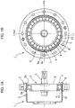
- FIG. 1A is a longitudinal cross-sectional view illustrating an example of a cup-type strain wave gearing to which the present invention is applied, and FIG. 1B is an end view thereof.
- the present invention can also be applied to a top-hat type strain wave gearing in the same manner.
- a strain wave gearing 1 has a rigid internally toothed gear 2 (rigid gear), a flexible externally toothed gear 3 (flexible gear) which has a cup shape and is arranged inside the internally toothed gear, and an elliptically-contoured wave generator 4 fitted inside the externally toothed gear.
- the externally toothed gear 3 has a cylindrical portion where external teeth 3a are formed, the cylindrical portion being flexed into an elliptical shape by the wave generator 4.
- the external teeth 3a located on both ends in a direction of a major axis Lmax of the elliptical shape are meshed with internal teeth 2a of the annular internally toothed gear 2.
- the wave generator 4 is provided with a rigid cam plate 6 fixed to the outer peripheral surface of a rotational input shaft 5 and a wave bearing 8 mounted on an elliptical outer peripheral surface 7 (non-circular outer peripheral surface) of the rigid cam plate 6.
- the wave bearing 8 is fitted into the externally toothed gear 3 in a state of being flexed into an elliptical shape by the rigid cam plate 6.
- the wave bearing supports the externally toothed gear 3 and the rigid cam plate 6 in a relatively rotatable state.
- the wave bearing 8 is composed of a full complement ball bearing, for example, a full complement deep groove ball bearing.
- the wave bearing 8 is provided with a circular inner race 9 flexible in a radial direction, a circular outer race 10 flexible in a radial direction, and a plurality of balls 11 that are inserted in a rollable state into an annular ball raceway groove formed between the inner and outer races.
- the respective balls 11 are inserted into the ball raceway groove in a state in which adjacent balls 11 are in contact with each other.
- a semicircular notch (not shown) is formed in one or both of the inner race 9 and outer race 10 for the balls 11 to be inserted into the ball raceway groove from outside.
- the rotational input shaft 5 of the wave generator 4 is connected to a motor shaft or other high-speed rotational input shaft (not shown).
- a position of meshing between both gears 2 and 3 is caused to move in a circumferential direction, whereby generating a relative rotation between the both gears 2 and 3 due to the difference in the number of teeth therebetween.
- the internally toothed gear 2 is secured so as not to rotate, the externally toothed gear 3 is connected to a load-side member, and reduced-speed rotation is derived from the externally toothed gear 3 and is transmitted to the load-side member.
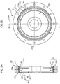
- FIG. 2A is a longitudinal cross-sectional view illustrating an example of a flat-type strain wave gearing to which the present invention is applied, and FIG. 2B is an end view thereof.
- a strain wave gearing 20 is provided, as a rigid internally toothed gear (rigid gear), with a first internally toothed gear 21 and a second internally toothed gear 22.
- the first and second internally toothed gears 21 and 22 are coaxially arranged in parallel, and a cylindrical flexible externally toothed gear 23 (flexible gear) is arranged inside the first and second internally toothed gears.
- a wave generator 24 having an elliptical contour is fitted inside the externally toothed gear 23.
- the wave generator 24 makes the externally toothed gear 23 to flex into an elliptical shape, and external teeth 23a on both end portions of a major axis Lmax of the elliptical shape are meshed with internal teeth 21a of the first internally toothed gear 21 and internal teeth 22a of the second internally toothed gear 22.
- the number of teeth of the first internally toothed gear 21 is larger than that of the second internally toothed gear 22 by 2n (n is a positive integer), and the number of teeth of the externally toothed gear 23 is the same as that of the second internally toothed gear 22.
- the external teeth 23a are meshed with the internal teeth 21a and 22a at positions on the major axis Lmax of the elliptical shape of the externally toothed gear 23.
- the wave generator 24 is provided with a rigid plug 25 and a wave bearing 27 mounted on an elliptical outer peripheral surface 26 of the rigid plug.
- the wave bearing 27 is composed of a full complement ball bearing and is provided with an inner-race raceway surface 29 formed on the elliptical outer peripheral surface of the rigid plug 25, a circular outer race 30 flexible in a radial direction, and a plurality of balls 31 inserted into an annular ball raceway groove formed between the inner-race raceway surface 29 and the outer race 30.
- the respective balls 31 are inserted into the ball raceway groove in a state in which adjacent balls 31 are in contact with each other.
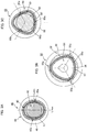
- FIGS. 3A, 3B and 3C are explanatory views illustrating examples of a strain wave gearing to which the present invention can be applied.
- the strain wave gearings illustrated in these drawings are employed as a cup-type or top-hat type strain wave gearing
- the illustrated strain wave gearings can be employed as a flat-type strain wave gearing.
- FIG. 3A illustrates a strain wave gearing 40 having a rigid externally toothed gear 42 (rigid gear) arranged on the innermost side thereof.
- An annular flexible internally toothed gear 43 (flexible gear) is arranged concentrically to surround the externally toothed gear 42.
- An annular wave generator 44 is arranged concentrically to surround the internally toothed gear 43.
- the internally toothed gear 43 is flexed into an elliptical shape by the wave generator 44.
- the internally toothed gear 43 flexed by the wave generator 44 is formed with meshing portions 45a and 45b with respect to the externally toothed gear 42 at two positions on both ends of a minor axis Lmin of the elliptical shape.
- the wave generator 44 is provided with an annular rigid cam plate 46 and a wave bearing 47 mounted inside the rigid cam plate.
- the wave bearing 47 is composed of a full complement ball bearing.
- the wave bearing 47 has an outer race integrally formed on the rigid cam plate 46.
- FIG. 3B illustrates a strain wave gearing 50 which is provided with a rigid internally toothed gear 52 (rigid gear), a flexible externally toothed gear 53 (flexible gear) arranged inside the internally toothed gear, and a non-circular contoured wave generator 54 fitted inside the flexible externally toothed gear.
- the externally toothed gear 53 has a portion where external teeth are formed, the portion being flexed by the wave generator 54 into a non-circular shape.
- the wave generator 54 is provided with a rigid cam plate 56 having a non-circular contour and a wave bearing 57 mounted on the outer periphery of the rigid cam plate.
- the wave bearing 57 is composed of a full complement deep groove ball bearing.
- the rigid cam plate 56 has a non-circular outer peripheral surface 56a defined by a closed curve that can be inscribed to a true circle at plural positions at equal intervals along a circumferential direction of the true circle.
- the non-circular outer peripheral surface 56a is a three-lobe shape defined by a closed curve that can be inscribed to a true circle at three equi-interval positions. It is also possible that the non-circular outer peripheral surface be defined by a closed curve that can be inscribed to a true circle at four or more positions at equal intervals.
- the thus shaped wave generator 54 makes the externally toothed gear 53 to flex into a shape along the non-circular contour of the wave generator 54, whereby forming meshing portions 55a, 55b and 55c with respect to the internally toothed gear 52 at three positions at an equiangular interval of 120 degrees.
- the wave generator 54 is connected with a motor shaft or other high-speed rotational input shaft.
- meshing positions between both gears 52 and 53 are moved in a circumferential direction to generate a relative rotation therebetween due to the difference in the number of teeth between these gears.
- the internally toothed gear 52 is secured so as not to rotate and the externally toothed gear 53 is connected to a load-side member
- reduced-speed rotation is taken out from the externally toothed gear 53 and is transmitted to the load-side member.
- the difference in the number of teeth between the both gears 52 and 53 is set to 3n (n is a positive integer).
- FIG. 3C illustrates a strain wave gearing 60, in which a flexible internally toothed gear 63 (flexible gear) is arranged outside of a rigid externally toothed gear 62 (rigid gear) and a wave generator 64 having a non-circular contoured inner peripheral surface is arranged on the outer peripheral side of the internally toothed gear 63.
- a flexible internally toothed gear 63 flexible gear
- a rigid externally toothed gear 62 rigid gear
- a wave generator 64 having a non-circular contoured inner peripheral surface is arranged on the outer peripheral side of the internally toothed gear 63.
- the wave generator 64 is provided with a rigid cam plate 66 having a non-circular inner peripheral surface 66a and a wave bearing 67 mounted on the non-circular inner peripheral surface 66a.
- the wave bearing 67 is a full complement deep groove ball bearing.
- the non-circular inner peripheral surface 66a of the rigid cam plate 66 is defined by a closed curve that can circumscribe a true circle on plural positions at equal intervals in a circumferential direction of the true circle.
- the non-circular inner peripheral surface 66a is a three-lobe shape that can circumscribe a true circle at three equiangular interval positions in the circumferential direction of the true circle.
- the non-circular inner peripheral surface be defined by a closed curve that can circumscribe a true circle at four or more positions at equiangular intervals in the circumferential direction of the true circle.
- the internally toothed gear 63 is flexed by the thus shaped wave generator 64 into a shape along the non-circular contour of the wave generator 64 and is formed with meshing portions 65a, 65b and 65c with respect to the externally toothed gear 62 at three positions at an angular interval of 120 degrees.
- meshing positions between both gears 62 and 63 are moved in a circumferential direction and a relative rotation due to the difference in the number of teeth between these gears is generated therebetween. This rotation can be taken out from the internally toothed gear 63.
- the difference in the number of teeth between these gears 62 and 63 is set to 3n (n is a positive integer).
Applications Claiming Priority (1)
| Application Number | Priority Date | Filing Date | Title |
|---|---|---|---|
| PCT/JP2017/032381 WO2019049296A1 (ja) | 2017-09-07 | 2017-09-07 | 波動歯車装置のウエーブベアリング |
Publications (2)
| Publication Number | Publication Date |
|---|---|
| EP3680513A1 true EP3680513A1 (de) | 2020-07-15 |
| EP3680513A4 EP3680513A4 (de) | 2021-01-27 |
Family
ID=65633810
Family Applications (1)
| Application Number | Title | Priority Date | Filing Date |
|---|---|---|---|
| EP17924333.2A Withdrawn EP3680513A4 (de) | 2017-09-07 | 2017-09-07 | Wellenlager für wellenbewegungsgetriebe |
Country Status (7)
| Country | Link |
|---|---|
| US (1) | US20200173532A1 (de) |
| EP (1) | EP3680513A4 (de) |
| JP (1) | JPWO2019049296A1 (de) |
| KR (1) | KR20200032741A (de) |
| CN (1) | CN111051733A (de) |
| TW (1) | TW201920844A (de) |
| WO (1) | WO2019049296A1 (de) |
Families Citing this family (5)
| Publication number | Priority date | Publication date | Assignee | Title |
|---|---|---|---|---|
| JP7003369B1 (ja) * | 2021-01-05 | 2022-02-10 | 泰一 岡田 | 玉軸受 |
| CN114857235A (zh) | 2021-02-04 | 2022-08-05 | 盟英科技股份有限公司 | 谐波减速装置 |
| TWI811833B (zh) * | 2021-02-04 | 2023-08-11 | 盟英科技股份有限公司 | 諧波減速裝置 |
| CN114370486B (zh) * | 2022-01-13 | 2023-08-11 | 珠海格力电器股份有限公司 | 一种谐波减速器上的三波凸轮波发生器及谐波减速器 |
| EP4249770A1 (de) * | 2022-03-25 | 2023-09-27 | C and M Robotics Co., Ltd. | Spannungswellengenerator für oberwellenreduzierer |
Family Cites Families (14)
| Publication number | Priority date | Publication date | Assignee | Title |
|---|---|---|---|---|
| US3214999A (en) * | 1964-04-09 | 1965-11-02 | Roger H Lapp | Harmonic drive |
| US3166949A (en) * | 1964-04-09 | 1965-01-26 | Roger H Lapp | Harmonic drive adjusting means |
| US3986412A (en) * | 1974-02-13 | 1976-10-19 | Usm Corporation | Redundant motor reducer drive |
| JPS5492246U (de) * | 1977-12-14 | 1979-06-29 | ||
| JP2681182B2 (ja) * | 1987-12-15 | 1997-11-26 | 光洋精工株式会社 | 玉軸受 |
| JPH11325060A (ja) * | 1998-05-12 | 1999-11-26 | Nippon Seiko Kk | 総ボール転がり軸受 |
| JP4807689B2 (ja) * | 2001-05-23 | 2011-11-02 | 株式会社ハーモニック・ドライブ・システムズ | 無潤滑型波動歯車装置 |
| JPWO2011001474A1 (ja) * | 2009-07-02 | 2012-12-10 | 株式会社ハーモニック・ドライブ・システムズ | 非円形ベアリング、波動発生器および波動歯車装置 |
| JP2011190826A (ja) * | 2010-03-11 | 2011-09-29 | Matex Kk | 波動歯車装置 |
| DE112011105478T5 (de) * | 2011-07-29 | 2014-04-24 | Harmonic Drive Systems Inc. | Innen verzahnte Getriebeeinheit mit zusammengesetztem Wälzlager und Wellgetriebe |
| KR101280291B1 (ko) * | 2012-10-31 | 2013-07-01 | 이윤규 | 탄성체와 핀이 결합된 치차를 구비한 플렉스플라인 및 이를 구비한 하모닉 드라이브 |
| JP2017026021A (ja) * | 2015-07-22 | 2017-02-02 | 株式会社ジェイテクト | 波動減速機、及び波動減速機用の玉軸受 |
| JP6536271B2 (ja) * | 2015-08-07 | 2019-07-03 | 株式会社ジェイテクト | 波動減速機、玉軸受、及び治具 |
| JP6884341B2 (ja) * | 2017-03-30 | 2021-06-09 | 公立大学法人大阪 | 土質判定方法 |
-
2017
- 2017-09-07 WO PCT/JP2017/032381 patent/WO2019049296A1/ja unknown
- 2017-09-07 US US16/640,197 patent/US20200173532A1/en not_active Abandoned
- 2017-09-07 CN CN201780094228.3A patent/CN111051733A/zh active Pending
- 2017-09-07 EP EP17924333.2A patent/EP3680513A4/de not_active Withdrawn
- 2017-09-07 KR KR1020207006107A patent/KR20200032741A/ko not_active Application Discontinuation
- 2017-09-07 JP JP2019540228A patent/JPWO2019049296A1/ja active Pending
-
2018
- 2018-07-27 TW TW107125968A patent/TW201920844A/zh unknown
Also Published As
| Publication number | Publication date |
|---|---|
| TW201920844A (zh) | 2019-06-01 |
| JPWO2019049296A1 (ja) | 2020-08-20 |
| EP3680513A4 (de) | 2021-01-27 |
| KR20200032741A (ko) | 2020-03-26 |
| US20200173532A1 (en) | 2020-06-04 |
| CN111051733A (zh) | 2020-04-21 |
| WO2019049296A1 (ja) | 2019-03-14 |
Similar Documents
| Publication | Publication Date | Title |
|---|---|---|
| EP3680513A1 (de) | Wellenlager für wellenbewegungsgetriebe | |
| US10060517B2 (en) | Strain wave gearing, frictional engagement wave device, and wave generator | |
| US9163710B2 (en) | Wave gear device and flexible externally toothed gear | |
| US9341252B2 (en) | Wave generator and strain wave gearing | |
| US9309921B2 (en) | Internally-toothed gear unit with composite roller bearing, and wave gear device | |
| US9797497B2 (en) | Strain wave gearing | |
| US8997607B2 (en) | Wave gear device and flexible internally toothed gear | |
| US20160178044A1 (en) | Strain wave gearing device | |
| WO2014181376A1 (ja) | 波動歯車装置の波動発生器 | |
| US9435418B2 (en) | Wave generator of strain wave gearing | |
| US10281007B2 (en) | Speed reducer | |
| US20210324948A1 (en) | Wave generator and strain wave gearing | |
| US10718420B2 (en) | Wave generator and strain wave gearing | |
| EP3492774B1 (de) | Wellengenerator und wellengetriebevorrichtung | |
| US11118668B2 (en) | Strain wave gearing | |
| KR101724659B1 (ko) | 역 사이클로이드 감속기 | |
| JP2020051541A (ja) | 歯車減速機 | |
| TWI694217B (zh) | 使用內接凸輪與圓筒齒輪之動力傳動裝置 | |
| JP2017089804A (ja) | トラクションドライブ機構を備えた波動歯車装置 | |
| CN110735887B (zh) | 无反向间隙的行星齿轮机构及行星减速机 | |
| JP2019011797A (ja) | 減速機 |
Legal Events
| Date | Code | Title | Description |
|---|---|---|---|
| PUAI | Public reference made under article 153(3) epc to a published international application that has entered the european phase |
Free format text: ORIGINAL CODE: 0009012 |
|
| STAA | Information on the status of an ep patent application or granted ep patent |
Free format text: STATUS: REQUEST FOR EXAMINATION WAS MADE |
|
| 17P | Request for examination filed |
Effective date: 20200306 |
|
| AK | Designated contracting states |
Kind code of ref document: A1 Designated state(s): AL AT BE BG CH CY CZ DE DK EE ES FI FR GB GR HR HU IE IS IT LI LT LU LV MC MK MT NL NO PL PT RO RS SE SI SK SM TR |
|
| AX | Request for extension of the european patent |
Extension state: BA ME |
|
| DAV | Request for validation of the european patent (deleted) | ||
| DAX | Request for extension of the european patent (deleted) | ||
| A4 | Supplementary search report drawn up and despatched |
Effective date: 20210111 |
|
| RIC1 | Information provided on ipc code assigned before grant |
Ipc: F16H 49/00 20060101AFI20201218BHEP |
|
| STAA | Information on the status of an ep patent application or granted ep patent |
Free format text: STATUS: THE APPLICATION HAS BEEN WITHDRAWN |
|
| 18W | Application withdrawn |
Effective date: 20210204 |