EP3680150A1 - Fahrzeug mit einem rahmen, der mit einer tragkonstruktion für zusatzeinheiten, insbesondere gasbehälter oder elektrische batterien, versehen ist - Google Patents
Fahrzeug mit einem rahmen, der mit einer tragkonstruktion für zusatzeinheiten, insbesondere gasbehälter oder elektrische batterien, versehen ist Download PDFInfo
- Publication number
- EP3680150A1 EP3680150A1 EP19150888.6A EP19150888A EP3680150A1 EP 3680150 A1 EP3680150 A1 EP 3680150A1 EP 19150888 A EP19150888 A EP 19150888A EP 3680150 A1 EP3680150 A1 EP 3680150A1
- Authority
- EP
- European Patent Office
- Prior art keywords
- frame
- vehicle
- longitudinal beams
- cross
- vehicle frame
- Prior art date
- Legal status (The legal status is an assumption and is not a legal conclusion. Google has not performed a legal analysis and makes no representation as to the accuracy of the status listed.)
- Granted
Links
- 239000002828 fuel tank Substances 0.000 claims abstract description 5
- 125000006850 spacer group Chemical group 0.000 claims description 3
- 230000000712 assembly Effects 0.000 description 6
- 238000000429 assembly Methods 0.000 description 6
- 239000002184 metal Substances 0.000 description 5
- 239000000446 fuel Substances 0.000 description 4
- 238000010276 construction Methods 0.000 description 2
- 238000003466 welding Methods 0.000 description 2
- 230000008878 coupling Effects 0.000 description 1
- 238000010168 coupling process Methods 0.000 description 1
- 238000005859 coupling reaction Methods 0.000 description 1
- 238000004519 manufacturing process Methods 0.000 description 1
- 238000005728 strengthening Methods 0.000 description 1
Images


Classifications
-
- B—PERFORMING OPERATIONS; TRANSPORTING
- B60—VEHICLES IN GENERAL
- B60K—ARRANGEMENT OR MOUNTING OF PROPULSION UNITS OR OF TRANSMISSIONS IN VEHICLES; ARRANGEMENT OR MOUNTING OF PLURAL DIVERSE PRIME-MOVERS IN VEHICLES; AUXILIARY DRIVES FOR VEHICLES; INSTRUMENTATION OR DASHBOARDS FOR VEHICLES; ARRANGEMENTS IN CONNECTION WITH COOLING, AIR INTAKE, GAS EXHAUST OR FUEL SUPPLY OF PROPULSION UNITS IN VEHICLES
- B60K15/00—Arrangement in connection with fuel supply of combustion engines or other fuel consuming energy converters, e.g. fuel cells; Mounting or construction of fuel tanks
- B60K15/03—Fuel tanks
- B60K15/063—Arrangement of tanks
- B60K15/067—Mounting of tanks
- B60K15/07—Mounting of tanks of gas tanks
-
- B—PERFORMING OPERATIONS; TRANSPORTING
- B60—VEHICLES IN GENERAL
- B60K—ARRANGEMENT OR MOUNTING OF PROPULSION UNITS OR OF TRANSMISSIONS IN VEHICLES; ARRANGEMENT OR MOUNTING OF PLURAL DIVERSE PRIME-MOVERS IN VEHICLES; AUXILIARY DRIVES FOR VEHICLES; INSTRUMENTATION OR DASHBOARDS FOR VEHICLES; ARRANGEMENTS IN CONNECTION WITH COOLING, AIR INTAKE, GAS EXHAUST OR FUEL SUPPLY OF PROPULSION UNITS IN VEHICLES
- B60K1/00—Arrangement or mounting of electrical propulsion units
- B60K1/04—Arrangement or mounting of electrical propulsion units of the electric storage means for propulsion
-
- B—PERFORMING OPERATIONS; TRANSPORTING
- B60—VEHICLES IN GENERAL
- B60K—ARRANGEMENT OR MOUNTING OF PROPULSION UNITS OR OF TRANSMISSIONS IN VEHICLES; ARRANGEMENT OR MOUNTING OF PLURAL DIVERSE PRIME-MOVERS IN VEHICLES; AUXILIARY DRIVES FOR VEHICLES; INSTRUMENTATION OR DASHBOARDS FOR VEHICLES; ARRANGEMENTS IN CONNECTION WITH COOLING, AIR INTAKE, GAS EXHAUST OR FUEL SUPPLY OF PROPULSION UNITS IN VEHICLES
- B60K15/00—Arrangement in connection with fuel supply of combustion engines or other fuel consuming energy converters, e.g. fuel cells; Mounting or construction of fuel tanks
- B60K15/03—Fuel tanks
- B60K15/03006—Gas tanks
-
- B—PERFORMING OPERATIONS; TRANSPORTING
- B60—VEHICLES IN GENERAL
- B60K—ARRANGEMENT OR MOUNTING OF PROPULSION UNITS OR OF TRANSMISSIONS IN VEHICLES; ARRANGEMENT OR MOUNTING OF PLURAL DIVERSE PRIME-MOVERS IN VEHICLES; AUXILIARY DRIVES FOR VEHICLES; INSTRUMENTATION OR DASHBOARDS FOR VEHICLES; ARRANGEMENTS IN CONNECTION WITH COOLING, AIR INTAKE, GAS EXHAUST OR FUEL SUPPLY OF PROPULSION UNITS IN VEHICLES
- B60K15/00—Arrangement in connection with fuel supply of combustion engines or other fuel consuming energy converters, e.g. fuel cells; Mounting or construction of fuel tanks
- B60K15/03—Fuel tanks
- B60K15/063—Arrangement of tanks
-
- B—PERFORMING OPERATIONS; TRANSPORTING
- B62—LAND VEHICLES FOR TRAVELLING OTHERWISE THAN ON RAILS
- B62D—MOTOR VEHICLES; TRAILERS
- B62D21/00—Understructures, i.e. chassis frame on which a vehicle body may be mounted
- B62D21/02—Understructures, i.e. chassis frame on which a vehicle body may be mounted comprising longitudinally or transversely arranged frame members
-
- B—PERFORMING OPERATIONS; TRANSPORTING
- B62—LAND VEHICLES FOR TRAVELLING OTHERWISE THAN ON RAILS
- B62D—MOTOR VEHICLES; TRAILERS
- B62D21/00—Understructures, i.e. chassis frame on which a vehicle body may be mounted
- B62D21/12—Understructures, i.e. chassis frame on which a vehicle body may be mounted assembled from readily detachable parts
-
- B—PERFORMING OPERATIONS; TRANSPORTING
- B60—VEHICLES IN GENERAL
- B60K—ARRANGEMENT OR MOUNTING OF PROPULSION UNITS OR OF TRANSMISSIONS IN VEHICLES; ARRANGEMENT OR MOUNTING OF PLURAL DIVERSE PRIME-MOVERS IN VEHICLES; AUXILIARY DRIVES FOR VEHICLES; INSTRUMENTATION OR DASHBOARDS FOR VEHICLES; ARRANGEMENTS IN CONNECTION WITH COOLING, AIR INTAKE, GAS EXHAUST OR FUEL SUPPLY OF PROPULSION UNITS IN VEHICLES
- B60K1/00—Arrangement or mounting of electrical propulsion units
- B60K1/04—Arrangement or mounting of electrical propulsion units of the electric storage means for propulsion
- B60K2001/0405—Arrangement or mounting of electrical propulsion units of the electric storage means for propulsion characterised by their position
- B60K2001/0438—Arrangement under the floor
-
- B—PERFORMING OPERATIONS; TRANSPORTING
- B60—VEHICLES IN GENERAL
- B60K—ARRANGEMENT OR MOUNTING OF PROPULSION UNITS OR OF TRANSMISSIONS IN VEHICLES; ARRANGEMENT OR MOUNTING OF PLURAL DIVERSE PRIME-MOVERS IN VEHICLES; AUXILIARY DRIVES FOR VEHICLES; INSTRUMENTATION OR DASHBOARDS FOR VEHICLES; ARRANGEMENTS IN CONNECTION WITH COOLING, AIR INTAKE, GAS EXHAUST OR FUEL SUPPLY OF PROPULSION UNITS IN VEHICLES
- B60K15/00—Arrangement in connection with fuel supply of combustion engines or other fuel consuming energy converters, e.g. fuel cells; Mounting or construction of fuel tanks
- B60K15/03—Fuel tanks
- B60K15/063—Arrangement of tanks
- B60K2015/0634—Arrangement of tanks the fuel tank is arranged below the vehicle floor
-
- B—PERFORMING OPERATIONS; TRANSPORTING
- B60—VEHICLES IN GENERAL
- B60Y—INDEXING SCHEME RELATING TO ASPECTS CROSS-CUTTING VEHICLE TECHNOLOGY
- B60Y2200/00—Type of vehicle
- B60Y2200/10—Road Vehicles
- B60Y2200/14—Trucks; Load vehicles, Busses
- B60Y2200/141—Light trucks
-
- B—PERFORMING OPERATIONS; TRANSPORTING
- B60—VEHICLES IN GENERAL
- B60Y—INDEXING SCHEME RELATING TO ASPECTS CROSS-CUTTING VEHICLE TECHNOLOGY
- B60Y2306/00—Other features of vehicle sub-units
- B60Y2306/01—Reducing damages in case of crash, e.g. by improving battery protection
Definitions
- the present invention relates to vehicles, and in particular to light duty vehicles of the type comprising:
- the object of the present invention is that of providing a vehicle of the above indicated type having an extremely resistant and reliable structure which at the same time has a simple construction and implies relatively reduced production costs.
- the invention provides a vehicle having the features which have been indicated in the foregoing and further characterized in that:
- connection plates of the auxiliary frame which are arranged at vertical planes parallel to the longitudinal direction of the vehicle frame are provided with flanges which project therefrom and constitute abutment elements which are in abutting contact with the lower walls of the two longitudinal beams of the vehicle frame.
- the auxiliary frame has a quadrangular configuration, including two longitudinal arms and two transverse arms rigidly connected to each other and further comprising at least one cross-member which connects the longitudinal arms to each other and has ends carrying said connection plates arranged at vertical planes parallel to the longitudinal direction of the vehicle frame.
- said cross-member of the auxiliary frame is in form of a hollow beam, with an upper wall, a lower wall, two lateral walls and end surfaces to which said connection plates are rigidly connected.
- the connection plates have portions projecting with respect to the cross-section of the cross-member, which are provided with holes or threaded bushes for engagement of screws for a rigid connection to the longitudinal beams of the vehicle frame.
- a specific application of the above-described structure is that of the housing of a plurality of tanks for gaseous fuel having a substantially cylindrical shape.
- said at least one cross-member of the auxiliary frame has concave lateral walls configured for defining a seat for respective gas tanks arranged in a horizontal position, with their axes arranged transversely to the longitudinal direction of the vehicle frame.
- to each lateral wall of the cross-member of the auxiliary frame there are associated belts for securing the gas tanks to the auxiliary frame.
- the vehicle further comprises a counter-frame comprising a pair of longitudinal beams extending above the longitudinal beams of the vehicle frame and rigidly connected thereto, and a plurality of cross-members which connect the longitudinal beams of the counter-frame to each other, said counter-frame acting as a spacer element in order to avoid a direct contact of the gas tanks with a floor panel of the vehicle.
- the auxiliary frame ensures a stable support for the auxiliary units, in particular for the tanks of gaseous fuel.
- the auxiliary frame is integrated within the vehicle frame so as to act as a structural element of the frame, adapted to give a contribution to the resistance of the frame against deformation. Therefore, at the area where the auxiliary frame is integrated within the vehicle frame, the latter does not have cross-members connecting the longitudinal beams, since the function of these cross-members is fulfilled by said auxiliary frame, which acts as a structural element adapted to counteract deformations, in particular twisting deformations, of the vehicle frame, similarly to, or even better than, what is normally achieved with the cross-members which connect the longitudinal beams of the vehicle frame to each other.
- a further advantage of the above-described structure lies in that assembling of the vehicle can be performed with extremely simple and quick operations.
- the tanks can be preassembled on the auxiliary frame, after which the unit constituted by the auxiliary frame with the fuel tanks preliminarily assembled thereon is mounted on the vehicle frame, by moving the unit towards the vehicle frame from below, until to obtain an abutment contact of the above-mentioned flanges acting as abutment elements, against the lower walls of the longitudinal beams of the frame.
- the auxiliary frame is arranged between the two longitudinal beams, with the above-mentioned connection plates arranged at the ends of the transverse elements of the auxiliary frame in contact with the facing inner walls of the longitudinal beams.
- the auxiliary frame carrying the gas tanks can be secured to the longitudinal beams of the vehicle frame.
- the structure of the vehicle can be also provided with more than one auxiliary frame, each auxiliary frame being arranged with one or more auxiliary units, such as gas tanks or electric batteries.
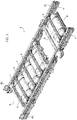
- reference numeral 1 generally designates the supporting structure of a light duty vehicle, including a cabin frame 2 and a vehicle frame 3.
- a vehicle frame 3 comprises a pair of longitudinal beams 4 connected to each other by a plurality of cross-members 5.
- the longitudinal beams 4 of the vehicle frame 3 have a hollow structure of welded sheet metal, with an upper wall 4A, a lower wall 4B, two outer lateral walls 4C and two inner lateral walls 4D. At least some of the cross-members 5 also have a hollow structure of welded sheet metal, including an upper wall, a lower wall and two lateral walls. In the case of the illustrated example, the ends of the cross-members 5 are rigidly connected to the longitudinal beams 4 of the vehicle frame 3 by means of intermediate supports 6 which are welded both to the cross-members 5 and the longitudinal beams 4.
- the cabin frame 2 can be made in any known way, but in any case comprises a pair of longitudinal beams 7 which are rigidly connected, for example by welding, to the front ends of the longitudinal beams 4 of the vehicle frame 3.
- the front ends of the longitudinal beams have coupling portions 4E having a U-shape which are engaged around the rear ends of the longitudinal beams 7 of the cabin frame 2.
- assemblies 8 for supporting tanks 9 for gaseous fuel (in particular CNG), which are in the form of substantially cylindrical containers, arranged in a horizontal position, with their axis directed transversely with respect to the longitudinal direction of the vehicle frame 3.
- CNG gaseous fuel
- the vehicle frame 3 is substantially identical to the frame 3 which has been described with reference to figure 1 , except for that cross-members 5 are omitted at the areas where the assemblies 8 must be mounted.
- the vehicle frame is provided with a first assembly 8 for supporting three pairs of tanks 9, and a further assembly 8 for supporting a single pair of tanks 9. It is clearly apparent that this arrangement is illustrated herein purely by way of non-limiting example.
- a vehicle frame can be indeed provided with any number of assemblies 8 (also a single assembly) and each assembly 8 can be provided for supporting any number of tanks 9.
- Each assembly 8 includes an auxiliary frame 80 which supports the tanks 9 and is rigidly connected to the vehicle frame 3.
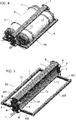
- Figure 5 shows a perspective view of the frame 80 of an assembly 8 which supports a pair of tanks 9.
- the auxiliary frame 80 has a quadrangular configuration, with two longitudinal arms 80L and two transverse arms 80T rigidly connected to each other.
- each of these arms is in the form of a metal bar with a square cross-section, so as to define a very rigid frame.
- the central portions of the two longitudinal arms 80L are connected to each after by a cross-member T which in the illustrated example is in the form of a hollow beam of welded sheet metal.
- the cross-member T has an upper wall T1, a lower wall T2 and two lateral walls T3.
- connection plates P arranged at a vertical planes parallel to the longitudinal direction of the vehicle frame and having lugs projecting from the cross-section of the cross-members T, which are provided with holes or threaded bushes B, for engagement of screws for a rigid connection to the longitudinal beams 4 of the vehicle frame 3.
- the connection plates P are in contact with the inner walls 4D of the longitudinal beam 4 of the vehicle frame 3 which are facing towards each other.
- the assemblies 8 are assembled from below on the vehicle frame 3.
- each flange F axially project outwardly from the connection plates P of each cross-member T, these flanges acting as abutment elements adapted to engage the lower walls 4B of the two longitudinal beams 4 of the vehicle frame 3.
- each flange F is constituted by a flat portion of an L-shaped element welded to the respective plate P.
- the vehicle frame 3 is provided, as indicated in the foregoing, both with an assembly 8 carrying a single pair of tanks 9 and with an assembly 8 carrying three pairs of tanks 9.
- This latter assembly also has an auxiliary frame 80 similar to that which has been described above with reference to figure 5 , except for that the longitudinal beams 80L have a longer extension and are connected to each other by many cross-members T. It is also absolutely possible, in place of a single frame 80 carrying the three pairs of tanks 9, to provide three frames 80 of the type shown in figure 5 , located at positions adjacent to each other.
- each auxiliary frame 80 fulfills a structural strengthening function for the vehicle frame 3 which is absolutely similar to, or even more effective than, the structural function fulfilled by the cross-members 5 of the vehicle frame.
- the cross-members 5 are omitted, but each auxiliary frame 80 is able to fulfills the same function, due to the rigid configuration of this frame and due to the connection which has been described above between the ends of the cross-members T and the longitudinal beams 4.
- the auxiliary frames 80 contribute to counteract the deformations of the frame 3 and above all they prevent undesired twisting deformations of this frame.
- the auxiliary frames 80 carrying the gas tanks 9 also fulfill a safety function, by absorbing impact energy in the case of a vehicle collision.
- each assembly 8 carries gas tanks having the cylindrical configuration which has been described above
- the lateral walls T3 of each beam T have a concave shape with a curved profile, so as to define a seat for the body of the adjacent tank 9.
- each wall T3 has slots 10 through which securing metal belts 11 ( figure 4 ) can be engaged, for securing the tanks 9 to the frames 80.
- a counter-frame 30 comprising a pair of longitudinal beams 31 connected to each other by cross-members 32.
- the longitudinal beams 31 are arranged above and along the longitudinal beam 4 of the vehicle frame 3 and are rigidly connected thereto, for example by means of screws or by welding, in the case of the illustrated example, also the cross-members 32 are connected to the longitudinal beams 31 with the interposition of intermediate supports 33, each of which is welded both to the longitudinal beams and to the cross-members 32.
- the counter-frame 30 is assembled from above (see arrow G in figure 3 ) on the vehicle frame 3. As shown in figure 2 , in the assembled condition, the counter-frame 3 acts as a spacer adapted to prevent a direct contact of the floor panel of the vehicle with the gas tanks 9.
- the invention is applicable also to the support of auxiliary units different from gas tanks, such as to the support of electric batteries.
Landscapes
- Engineering & Computer Science (AREA)
- Chemical & Material Sciences (AREA)
- Combustion & Propulsion (AREA)
- Transportation (AREA)
- Mechanical Engineering (AREA)
- Life Sciences & Earth Sciences (AREA)
- Sustainable Development (AREA)
- Sustainable Energy (AREA)
- Body Structure For Vehicles (AREA)
- Cooling, Air Intake And Gas Exhaust, And Fuel Tank Arrangements In Propulsion Units (AREA)
Priority Applications (5)
| Application Number | Priority Date | Filing Date | Title |
|---|---|---|---|
| EP19150888.6A EP3680150B1 (de) | 2019-01-09 | 2019-01-09 | Fahrzeug mit einem rahmen, der mit einer tragkonstruktion für zusatzeinheiten, insbesondere gasbehälter oder elektrische batterien, versehen ist |
| PCT/IB2019/056857 WO2020144498A1 (en) | 2019-01-09 | 2019-08-13 | Vehicle having a frame provided with a supporting structure for auxiliary units, in particular gas tanks or electric batteries |
| BR112021012409-8A BR112021012409A2 (pt) | 2019-01-09 | 2019-08-13 | Veículo tendo uma estrutura fornecida com uma estrutura de suporte para unidades auxiliares, em particular tanques de gás ou baterias elétricas |
| CN201980088535.XA CN113272205B (zh) | 2019-01-09 | 2019-08-13 | 具有设有用于辅助单元、特别是气体箱或电池的支承结构的框架的车辆 |
| US17/421,093 US20220105799A1 (en) | 2019-01-09 | 2019-08-13 | Vehicle having a frame provided with a supporting structure for auxiliary units, in particular gas tanks or electric batteries |
Applications Claiming Priority (1)
| Application Number | Priority Date | Filing Date | Title |
|---|---|---|---|
| EP19150888.6A EP3680150B1 (de) | 2019-01-09 | 2019-01-09 | Fahrzeug mit einem rahmen, der mit einer tragkonstruktion für zusatzeinheiten, insbesondere gasbehälter oder elektrische batterien, versehen ist |
Publications (2)
| Publication Number | Publication Date |
|---|---|
| EP3680150A1 true EP3680150A1 (de) | 2020-07-15 |
| EP3680150B1 EP3680150B1 (de) | 2021-02-24 |
Family
ID=65041555
Family Applications (1)
| Application Number | Title | Priority Date | Filing Date |
|---|---|---|---|
| EP19150888.6A Active EP3680150B1 (de) | 2019-01-09 | 2019-01-09 | Fahrzeug mit einem rahmen, der mit einer tragkonstruktion für zusatzeinheiten, insbesondere gasbehälter oder elektrische batterien, versehen ist |
Country Status (5)
| Country | Link |
|---|---|
| US (1) | US20220105799A1 (de) |
| EP (1) | EP3680150B1 (de) |
| CN (1) | CN113272205B (de) |
| BR (1) | BR112021012409A2 (de) |
| WO (1) | WO2020144498A1 (de) |
Cited By (2)
| Publication number | Priority date | Publication date | Assignee | Title |
|---|---|---|---|---|
| WO2023280385A1 (en) * | 2021-07-06 | 2023-01-12 | Volvo Truck Corporation | A suspension arrangement for an energy storage system |
| FR3130699A1 (fr) * | 2021-12-16 | 2023-06-23 | Renault | Dispositif de maintien d’au moins un élément de stockage d’énergie agencé sous le plancher d’un véhicule automobile |
Families Citing this family (6)
| Publication number | Priority date | Publication date | Assignee | Title |
|---|---|---|---|---|
| WO2021126455A1 (en) * | 2019-12-16 | 2021-06-24 | Nikola Corporation | Integrated fuel storage system |
| DE202020103686U1 (de) * | 2020-06-26 | 2021-09-28 | Alois Kober Gmbh | Anbauchassis |
| JP7481221B2 (ja) * | 2020-09-30 | 2024-05-10 | 株式会社Subaru | 燃料電池車両 |
| CN112896317B (zh) * | 2021-03-12 | 2023-03-14 | 中国重汽集团济南动力有限公司 | 一种短轴距车架总成及安装方法 |
| CN113635973A (zh) * | 2021-07-16 | 2021-11-12 | 河南德力新能源汽车有限公司 | 一种桁架式车架燃料电池载货汽车布置方案 |
| CN117533157A (zh) * | 2023-11-10 | 2024-02-09 | 陕西质镁融合科技有限公司 | 一种桁架式轻量化的框架 |
Citations (6)
| Publication number | Priority date | Publication date | Assignee | Title |
|---|---|---|---|---|
| US20040148778A1 (en) * | 2003-01-31 | 2004-08-05 | Fleming Sean M. | Method for manufacturing a vehicle frame assembly |
| US20050062251A1 (en) * | 2003-09-22 | 2005-03-24 | Ramsey John E. | Vehicle frame having air tank cross member |
| DE202010008375U1 (de) * | 2010-08-26 | 2011-11-28 | Al-Ko Kober Ag | Fahrgestell |
| JP2017039362A (ja) * | 2015-08-18 | 2017-02-23 | スズキ株式会社 | 車両用燃料ガスタンクの取付け構造 |
| EP3296186A1 (de) * | 2016-09-20 | 2018-03-21 | Schmitz Cargobull AG | Nutzfahrzeug mit einem aufbau und verfahren zum montieren eines aufbaus auf einem nutzfahrzeug |
| WO2018144780A1 (en) * | 2017-02-01 | 2018-08-09 | Agility Fuel Systems Llc | Tailgate fuel storage system |
Family Cites Families (9)
| Publication number | Priority date | Publication date | Assignee | Title |
|---|---|---|---|---|
| US5366246A (en) * | 1993-05-11 | 1994-11-22 | Navistar International Transportation Corp. | Vehicle fuel tank mounting and protective cage |
| US5658013A (en) * | 1995-09-20 | 1997-08-19 | The Babcock & Wilcox Company | Fuel tank for vehicles for holding and dispensing both a liquid and gaseous fuel therein |
| DE102006026118A1 (de) * | 2006-06-03 | 2007-12-06 | GM Global Technology Operations, Inc., Detroit | Befestigungsanordnung für Gastank eines Kraftfahrzeugs |
| JP5061941B2 (ja) * | 2008-02-18 | 2012-10-31 | 日産自動車株式会社 | 車両のバッテリ搭載構造 |
| DE102011014334A1 (de) * | 2011-03-18 | 2012-09-20 | GM Global Technology Operations LLC (n. d. Gesetzen des Staates Delaware) | Halterung für Gastanks |
| DE102012024842A1 (de) * | 2012-12-19 | 2014-06-26 | Daimler Ag | Bauteilanordnung, insbesondere eines Kraftfahrzeugs |
| CA2919692A1 (en) * | 2013-08-02 | 2015-02-05 | Alternative Fuel Containers, Llc | Conformable fuel gas tank |
| EP3263424B1 (de) * | 2016-07-01 | 2018-10-03 | FCA Italy S.p.A. | Einheit mit längsträger und frontplatte für eine kraftfahrzeugkonstruktion |
| DE102016010138A1 (de) * | 2016-08-19 | 2017-02-16 | Daimler Ag | Befestigungsanordnung für einen Betriebsmittelbehälter zwischen den Längsträgern eines Rahmens eines Lastkraftwagens |
-
2019
- 2019-01-09 EP EP19150888.6A patent/EP3680150B1/de active Active
- 2019-08-13 CN CN201980088535.XA patent/CN113272205B/zh active Active
- 2019-08-13 WO PCT/IB2019/056857 patent/WO2020144498A1/en active Application Filing
- 2019-08-13 US US17/421,093 patent/US20220105799A1/en active Pending
- 2019-08-13 BR BR112021012409-8A patent/BR112021012409A2/pt unknown
Patent Citations (6)
| Publication number | Priority date | Publication date | Assignee | Title |
|---|---|---|---|---|
| US20040148778A1 (en) * | 2003-01-31 | 2004-08-05 | Fleming Sean M. | Method for manufacturing a vehicle frame assembly |
| US20050062251A1 (en) * | 2003-09-22 | 2005-03-24 | Ramsey John E. | Vehicle frame having air tank cross member |
| DE202010008375U1 (de) * | 2010-08-26 | 2011-11-28 | Al-Ko Kober Ag | Fahrgestell |
| JP2017039362A (ja) * | 2015-08-18 | 2017-02-23 | スズキ株式会社 | 車両用燃料ガスタンクの取付け構造 |
| EP3296186A1 (de) * | 2016-09-20 | 2018-03-21 | Schmitz Cargobull AG | Nutzfahrzeug mit einem aufbau und verfahren zum montieren eines aufbaus auf einem nutzfahrzeug |
| WO2018144780A1 (en) * | 2017-02-01 | 2018-08-09 | Agility Fuel Systems Llc | Tailgate fuel storage system |
Cited By (2)
| Publication number | Priority date | Publication date | Assignee | Title |
|---|---|---|---|---|
| WO2023280385A1 (en) * | 2021-07-06 | 2023-01-12 | Volvo Truck Corporation | A suspension arrangement for an energy storage system |
| FR3130699A1 (fr) * | 2021-12-16 | 2023-06-23 | Renault | Dispositif de maintien d’au moins un élément de stockage d’énergie agencé sous le plancher d’un véhicule automobile |
Also Published As
| Publication number | Publication date |
|---|---|
| US20220105799A1 (en) | 2022-04-07 |
| EP3680150B1 (de) | 2021-02-24 |
| CN113272205B (zh) | 2023-05-05 |
| WO2020144498A1 (en) | 2020-07-16 |
| CN113272205A (zh) | 2021-08-17 |
| BR112021012409A2 (pt) | 2021-09-08 |
Similar Documents
| Publication | Publication Date | Title |
|---|---|---|
| EP3680150B1 (de) | Fahrzeug mit einem rahmen, der mit einer tragkonstruktion für zusatzeinheiten, insbesondere gasbehälter oder elektrische batterien, versehen ist | |
| US7513329B2 (en) | Vehicle rear body structure | |
| US9758029B2 (en) | Battery frame and vehicle battery mounting structure | |
| US7828330B2 (en) | Vehicle front body structure | |
| US9776665B2 (en) | Load path control mechanism | |
| US8070217B2 (en) | Vehicle body rear part structure | |
| US8276982B2 (en) | Detachable-body vehicle frame | |
| KR20050085946A (ko) | 다용도 차량을 위한 전방프레임부품 | |
| KR101610766B1 (ko) | 차량 전부 구조 | |
| US11447184B2 (en) | Vehicle body lower structure | |
| CN114348119A (zh) | 用于电动车辆的并列型侧梁结构 | |
| US20060138764A1 (en) | Front-end vehicle structure | |
| JP2006111076A (ja) | 車体骨格構造 | |
| CN109835418B (zh) | 汽车用横梁以及汽车用横梁结构 | |
| JP2017114162A (ja) | サスペンションクロスメンバ構造 | |
| CN217994550U (zh) | 卡车的车架结构及卡车 | |
| CN116374005A (zh) | 纵梁结构、车架总成及纵梁结构制造方法 | |
| CN209972579U (zh) | 副车架总成及车辆 | |
| CN218431405U (zh) | 一种模块化轻量型前后轴骨架 | |
| KR102149401B1 (ko) | 알루미늄 프레임의 서스펜션 장착부 강성보강구조 | |
| CN214607394U (zh) | 车辆 | |
| CN217864012U (zh) | 防撞梁安装板和具有其的防撞梁组件、车辆 | |
| CN217435837U (zh) | 一种副车架与车身连接支架及汽车车体 | |
| JP5737097B2 (ja) | 車両の前部車体構造 | |
| KR20110054339A (ko) | 차량의 크로스멤버 |
Legal Events
| Date | Code | Title | Description |
|---|---|---|---|
| PUAI | Public reference made under article 153(3) epc to a published international application that has entered the european phase |
Free format text: ORIGINAL CODE: 0009012 |
|
| STAA | Information on the status of an ep patent application or granted ep patent |
Free format text: STATUS: REQUEST FOR EXAMINATION WAS MADE |
|
| 17P | Request for examination filed |
Effective date: 20191021 |
|
| AK | Designated contracting states |
Kind code of ref document: A1 Designated state(s): AL AT BE BG CH CY CZ DE DK EE ES FI FR GB GR HR HU IE IS IT LI LT LU LV MC MK MT NL NO PL PT RO RS SE SI SK SM TR |
|
| AX | Request for extension of the european patent |
Extension state: BA ME |
|
| RIC1 | Information provided on ipc code assigned before grant |
Ipc: B60K 1/04 20190101ALI20200713BHEP Ipc: B60K 15/07 20060101ALI20200713BHEP Ipc: B62D 21/12 20060101ALI20200713BHEP Ipc: B60K 15/063 20060101ALI20200713BHEP Ipc: B62D 21/02 20060101AFI20200713BHEP Ipc: B60K 15/03 20060101ALI20200713BHEP |
|
| GRAP | Despatch of communication of intention to grant a patent |
Free format text: ORIGINAL CODE: EPIDOSNIGR1 |
|
| STAA | Information on the status of an ep patent application or granted ep patent |
Free format text: STATUS: GRANT OF PATENT IS INTENDED |
|
| INTG | Intention to grant announced |
Effective date: 20200827 |
|
| GRAS | Grant fee paid |
Free format text: ORIGINAL CODE: EPIDOSNIGR3 |
|
| GRAA | (expected) grant |
Free format text: ORIGINAL CODE: 0009210 |
|
| STAA | Information on the status of an ep patent application or granted ep patent |
Free format text: STATUS: THE PATENT HAS BEEN GRANTED |
|
| AK | Designated contracting states |
Kind code of ref document: B1 Designated state(s): AL AT BE BG CH CY CZ DE DK EE ES FI FR GB GR HR HU IE IS IT LI LT LU LV MC MK MT NL NO PL PT RO RS SE SI SK SM TR |
|
| REG | Reference to a national code |
Ref country code: CH Ref legal event code: EP |
|
| REG | Reference to a national code |
Ref country code: AT Ref legal event code: REF Ref document number: 1364100 Country of ref document: AT Kind code of ref document: T Effective date: 20210315 |
|
| REG | Reference to a national code |
Ref country code: IE Ref legal event code: FG4D |
|
| REG | Reference to a national code |
Ref country code: DE Ref legal event code: R096 Ref document number: 602019002640 Country of ref document: DE |
|
| REG | Reference to a national code |
Ref country code: LT Ref legal event code: MG9D |
|
| REG | Reference to a national code |
Ref country code: NL Ref legal event code: MP Effective date: 20210224 |
|
| PG25 | Lapsed in a contracting state [announced via postgrant information from national office to epo] |
Ref country code: HR Free format text: LAPSE BECAUSE OF FAILURE TO SUBMIT A TRANSLATION OF THE DESCRIPTION OR TO PAY THE FEE WITHIN THE PRESCRIBED TIME-LIMIT Effective date: 20210224 Ref country code: FI Free format text: LAPSE BECAUSE OF FAILURE TO SUBMIT A TRANSLATION OF THE DESCRIPTION OR TO PAY THE FEE WITHIN THE PRESCRIBED TIME-LIMIT Effective date: 20210224 Ref country code: GR Free format text: LAPSE BECAUSE OF FAILURE TO SUBMIT A TRANSLATION OF THE DESCRIPTION OR TO PAY THE FEE WITHIN THE PRESCRIBED TIME-LIMIT Effective date: 20210525 Ref country code: BG Free format text: LAPSE BECAUSE OF FAILURE TO SUBMIT A TRANSLATION OF THE DESCRIPTION OR TO PAY THE FEE WITHIN THE PRESCRIBED TIME-LIMIT Effective date: 20210524 Ref country code: NO Free format text: LAPSE BECAUSE OF FAILURE TO SUBMIT A TRANSLATION OF THE DESCRIPTION OR TO PAY THE FEE WITHIN THE PRESCRIBED TIME-LIMIT Effective date: 20210524 Ref country code: PT Free format text: LAPSE BECAUSE OF FAILURE TO SUBMIT A TRANSLATION OF THE DESCRIPTION OR TO PAY THE FEE WITHIN THE PRESCRIBED TIME-LIMIT Effective date: 20210624 Ref country code: LT Free format text: LAPSE BECAUSE OF FAILURE TO SUBMIT A TRANSLATION OF THE DESCRIPTION OR TO PAY THE FEE WITHIN THE PRESCRIBED TIME-LIMIT Effective date: 20210224 |
|
| REG | Reference to a national code |
Ref country code: AT Ref legal event code: MK05 Ref document number: 1364100 Country of ref document: AT Kind code of ref document: T Effective date: 20210224 |
|
| PG25 | Lapsed in a contracting state [announced via postgrant information from national office to epo] |
Ref country code: SE Free format text: LAPSE BECAUSE OF FAILURE TO SUBMIT A TRANSLATION OF THE DESCRIPTION OR TO PAY THE FEE WITHIN THE PRESCRIBED TIME-LIMIT Effective date: 20210224 Ref country code: RS Free format text: LAPSE BECAUSE OF FAILURE TO SUBMIT A TRANSLATION OF THE DESCRIPTION OR TO PAY THE FEE WITHIN THE PRESCRIBED TIME-LIMIT Effective date: 20210224 Ref country code: NL Free format text: LAPSE BECAUSE OF FAILURE TO SUBMIT A TRANSLATION OF THE DESCRIPTION OR TO PAY THE FEE WITHIN THE PRESCRIBED TIME-LIMIT Effective date: 20210224 Ref country code: PL Free format text: LAPSE BECAUSE OF FAILURE TO SUBMIT A TRANSLATION OF THE DESCRIPTION OR TO PAY THE FEE WITHIN THE PRESCRIBED TIME-LIMIT Effective date: 20210224 Ref country code: LV Free format text: LAPSE BECAUSE OF FAILURE TO SUBMIT A TRANSLATION OF THE DESCRIPTION OR TO PAY THE FEE WITHIN THE PRESCRIBED TIME-LIMIT Effective date: 20210224 |
|
| PG25 | Lapsed in a contracting state [announced via postgrant information from national office to epo] |
Ref country code: IS Free format text: LAPSE BECAUSE OF FAILURE TO SUBMIT A TRANSLATION OF THE DESCRIPTION OR TO PAY THE FEE WITHIN THE PRESCRIBED TIME-LIMIT Effective date: 20210624 |
|
| PG25 | Lapsed in a contracting state [announced via postgrant information from national office to epo] |
Ref country code: CZ Free format text: LAPSE BECAUSE OF FAILURE TO SUBMIT A TRANSLATION OF THE DESCRIPTION OR TO PAY THE FEE WITHIN THE PRESCRIBED TIME-LIMIT Effective date: 20210224 Ref country code: EE Free format text: LAPSE BECAUSE OF FAILURE TO SUBMIT A TRANSLATION OF THE DESCRIPTION OR TO PAY THE FEE WITHIN THE PRESCRIBED TIME-LIMIT Effective date: 20210224 Ref country code: SM Free format text: LAPSE BECAUSE OF FAILURE TO SUBMIT A TRANSLATION OF THE DESCRIPTION OR TO PAY THE FEE WITHIN THE PRESCRIBED TIME-LIMIT Effective date: 20210224 Ref country code: AT Free format text: LAPSE BECAUSE OF FAILURE TO SUBMIT A TRANSLATION OF THE DESCRIPTION OR TO PAY THE FEE WITHIN THE PRESCRIBED TIME-LIMIT Effective date: 20210224 |
|
| REG | Reference to a national code |
Ref country code: DE Ref legal event code: R097 Ref document number: 602019002640 Country of ref document: DE |
|
| PG25 | Lapsed in a contracting state [announced via postgrant information from national office to epo] |
Ref country code: RO Free format text: LAPSE BECAUSE OF FAILURE TO SUBMIT A TRANSLATION OF THE DESCRIPTION OR TO PAY THE FEE WITHIN THE PRESCRIBED TIME-LIMIT Effective date: 20210224 Ref country code: SK Free format text: LAPSE BECAUSE OF FAILURE TO SUBMIT A TRANSLATION OF THE DESCRIPTION OR TO PAY THE FEE WITHIN THE PRESCRIBED TIME-LIMIT Effective date: 20210224 Ref country code: DK Free format text: LAPSE BECAUSE OF FAILURE TO SUBMIT A TRANSLATION OF THE DESCRIPTION OR TO PAY THE FEE WITHIN THE PRESCRIBED TIME-LIMIT Effective date: 20210224 |
|
| PLBE | No opposition filed within time limit |
Free format text: ORIGINAL CODE: 0009261 |
|
| STAA | Information on the status of an ep patent application or granted ep patent |
Free format text: STATUS: NO OPPOSITION FILED WITHIN TIME LIMIT |
|
| PG25 | Lapsed in a contracting state [announced via postgrant information from national office to epo] |
Ref country code: AL Free format text: LAPSE BECAUSE OF FAILURE TO SUBMIT A TRANSLATION OF THE DESCRIPTION OR TO PAY THE FEE WITHIN THE PRESCRIBED TIME-LIMIT Effective date: 20210224 Ref country code: ES Free format text: LAPSE BECAUSE OF FAILURE TO SUBMIT A TRANSLATION OF THE DESCRIPTION OR TO PAY THE FEE WITHIN THE PRESCRIBED TIME-LIMIT Effective date: 20210224 |
|
| 26N | No opposition filed |
Effective date: 20211125 |
|
| PG25 | Lapsed in a contracting state [announced via postgrant information from national office to epo] |
Ref country code: IS Free format text: LAPSE BECAUSE OF FAILURE TO SUBMIT A TRANSLATION OF THE DESCRIPTION OR TO PAY THE FEE WITHIN THE PRESCRIBED TIME-LIMIT Effective date: 20210624 |
|
| PG25 | Lapsed in a contracting state [announced via postgrant information from national office to epo] |
Ref country code: MC Free format text: LAPSE BECAUSE OF FAILURE TO SUBMIT A TRANSLATION OF THE DESCRIPTION OR TO PAY THE FEE WITHIN THE PRESCRIBED TIME-LIMIT Effective date: 20210224 |
|
| REG | Reference to a national code |
Ref country code: CH Ref legal event code: PL |
|
| REG | Reference to a national code |
Ref country code: BE Ref legal event code: MM Effective date: 20220131 |
|
| PG25 | Lapsed in a contracting state [announced via postgrant information from national office to epo] |
Ref country code: LU Free format text: LAPSE BECAUSE OF NON-PAYMENT OF DUE FEES Effective date: 20220109 |
|
| PG25 | Lapsed in a contracting state [announced via postgrant information from national office to epo] |
Ref country code: BE Free format text: LAPSE BECAUSE OF NON-PAYMENT OF DUE FEES Effective date: 20220131 |
|
| PG25 | Lapsed in a contracting state [announced via postgrant information from national office to epo] |
Ref country code: LI Free format text: LAPSE BECAUSE OF NON-PAYMENT OF DUE FEES Effective date: 20220131 Ref country code: CH Free format text: LAPSE BECAUSE OF NON-PAYMENT OF DUE FEES Effective date: 20220131 |
|
| PG25 | Lapsed in a contracting state [announced via postgrant information from national office to epo] |
Ref country code: IE Free format text: LAPSE BECAUSE OF NON-PAYMENT OF DUE FEES Effective date: 20220109 |
|
| PGFP | Annual fee paid to national office [announced via postgrant information from national office to epo] |
Ref country code: IT Payment date: 20230103 Year of fee payment: 5 |
|
| GBPC | Gb: european patent ceased through non-payment of renewal fee |
Effective date: 20230109 |
|
| PG25 | Lapsed in a contracting state [announced via postgrant information from national office to epo] |
Ref country code: GB Free format text: LAPSE BECAUSE OF NON-PAYMENT OF DUE FEES Effective date: 20230109 |
|
| PGFP | Annual fee paid to national office [announced via postgrant information from national office to epo] |
Ref country code: FR Payment date: 20231219 Year of fee payment: 6 |
|
| PG25 | Lapsed in a contracting state [announced via postgrant information from national office to epo] |
Ref country code: MK Free format text: LAPSE BECAUSE OF FAILURE TO SUBMIT A TRANSLATION OF THE DESCRIPTION OR TO PAY THE FEE WITHIN THE PRESCRIBED TIME-LIMIT Effective date: 20210224 Ref country code: CY Free format text: LAPSE BECAUSE OF FAILURE TO SUBMIT A TRANSLATION OF THE DESCRIPTION OR TO PAY THE FEE WITHIN THE PRESCRIBED TIME-LIMIT Effective date: 20210224 |
|
| PGFP | Annual fee paid to national office [announced via postgrant information from national office to epo] |
Ref country code: DE Payment date: 20231219 Year of fee payment: 6 |