EP3680025B1 - Wischvorrichtung aus viskosem material - Google Patents
Wischvorrichtung aus viskosem material Download PDFInfo
- Publication number
- EP3680025B1 EP3680025B1 EP18853808.6A EP18853808A EP3680025B1 EP 3680025 B1 EP3680025 B1 EP 3680025B1 EP 18853808 A EP18853808 A EP 18853808A EP 3680025 B1 EP3680025 B1 EP 3680025B1
- Authority
- EP
- European Patent Office
- Prior art keywords
- spatula
- sheet
- wiping
- groove
- viscous material
- Prior art date
- Legal status (The legal status is an assumption and is not a legal conclusion. Google has not performed a legal analysis and makes no representation as to the accuracy of the status listed.)
- Active
Links
Images



Classifications
-
- B—PERFORMING OPERATIONS; TRANSPORTING
- B08—CLEANING
- B08B—CLEANING IN GENERAL; PREVENTION OF FOULING IN GENERAL
- B08B1/00—Cleaning by methods involving the use of tools
- B08B1/10—Cleaning by methods involving the use of tools characterised by the type of cleaning tool
- B08B1/16—Rigid blades, e.g. scrapers; Flexible blades, e.g. wipers
- B08B1/165—Scrapers
-
- B—PERFORMING OPERATIONS; TRANSPORTING
- B05—SPRAYING OR ATOMISING IN GENERAL; APPLYING FLUENT MATERIALS TO SURFACES, IN GENERAL
- B05C—APPARATUS FOR APPLYING FLUENT MATERIALS TO SURFACES, IN GENERAL
- B05C11/00—Component parts, details or accessories not specifically provided for in groups B05C1/00 - B05C9/00
- B05C11/02—Apparatus for spreading or distributing liquids or other fluent materials already applied to a surface ; Controlling means therefor; Control of the thickness of a coating by spreading or distributing liquids or other fluent materials already applied to the coated surface
- B05C11/023—Apparatus for spreading or distributing liquids or other fluent materials already applied to a surface
-
- B—PERFORMING OPERATIONS; TRANSPORTING
- B05—SPRAYING OR ATOMISING IN GENERAL; APPLYING FLUENT MATERIALS TO SURFACES, IN GENERAL
- B05C—APPARATUS FOR APPLYING FLUENT MATERIALS TO SURFACES, IN GENERAL
- B05C11/00—Component parts, details or accessories not specifically provided for in groups B05C1/00 - B05C9/00
- B05C11/02—Apparatus for spreading or distributing liquids or other fluent materials already applied to a surface ; Controlling means therefor; Control of the thickness of a coating by spreading or distributing liquids or other fluent materials already applied to the coated surface
-
- B—PERFORMING OPERATIONS; TRANSPORTING
- B05—SPRAYING OR ATOMISING IN GENERAL; APPLYING FLUENT MATERIALS TO SURFACES, IN GENERAL
- B05C—APPARATUS FOR APPLYING FLUENT MATERIALS TO SURFACES, IN GENERAL
- B05C11/00—Component parts, details or accessories not specifically provided for in groups B05C1/00 - B05C9/00
- B05C11/10—Storage, supply or control of liquid or other fluent material; Recovery of excess liquid or other fluent material
-
- B—PERFORMING OPERATIONS; TRANSPORTING
- B08—CLEANING
- B08B—CLEANING IN GENERAL; PREVENTION OF FOULING IN GENERAL
- B08B1/00—Cleaning by methods involving the use of tools
- B08B1/10—Cleaning by methods involving the use of tools characterised by the type of cleaning tool
- B08B1/14—Wipes; Absorbent members, e.g. swabs or sponges
- B08B1/143—Wipes
-
- B—PERFORMING OPERATIONS; TRANSPORTING
- B08—CLEANING
- B08B—CLEANING IN GENERAL; PREVENTION OF FOULING IN GENERAL
- B08B1/00—Cleaning by methods involving the use of tools
- B08B1/30—Cleaning by methods involving the use of tools by movement of cleaning members over a surface
Definitions
- the present invention relates to a device for wiping a viscous material such as a sealant or an adhesive with a sheet.
- Patent Literature 1 discloses a viscous material coating device that can be applied to an automobile manufacturing site. This device includes a mixing head that is attached to a robot hand and discharges a sealant while moving along a predetermined locus.
- the incidental work includes, for example, the work of shaping the surface of the applied viscous material with a spatula, and the work of wiping the viscous material attached to the nozzle in the application work or the viscous material attached to the spatula in the shaping work with a sheet.
- An object of the present invention is to provide a device that contributes to labor saving of work incidental to viscous material application work.
- WO 2015/149441 A1 shows a wiping mechanism and an automatic cleaning device provided with such a wiping mechanism, comprising a sheet support jig. Said sheet support jig has a gap recessed in a sheet facing surface of the sheet support jig.
- CN 103 364 252 A discloses a device for wiping an applicator paddle for a dying machine, in which the paddle is manually inserted in a groove.
- a viscous material wiping device according to the present invention is laid down in claim 1.
- the spatula moves within the groove and passes through the wiping portion having a groove width substantially equal to the outer dimension of the tip.
- the sheet is pressed with the spatula and is fitted into the groove so as to sandwich both sides of the spatula. Therefore, when passing through the wiping portion, the viscous material attached to the tip of the spatula can be wiped with the sheet. Since this operation is automated by the control device and the moving mechanism, labor of the wiping work of the viscous material can be saved.
- the device which contributes to labor saving of a work incidental to the viscous material application work can be provided.
- FIGS. 1A to 1C show a manufacturing site to which a viscous material wiping device according to an embodiment (hereinafter simply referred to as "wiping device 1") is applied.
- a viscous material 95 is applied to a mating portion 93 of workpieces 91 and 92 formed by overlapping or butting the two workpieces 91 and 92.
- the mating portion 93 it may be applied to an opening edge portion formed in the workpiece.
- a manufacturing site of a vehicle for example, an aircraft or an automobile
- an industrial machine for example, a construction machine, an agricultural machine, or a machine tool
- the workpieces 91 and 92 are plate-shaped, and the mating portion 93 is formed by overlapping the workpieces 91 and 92.
- the mating portion 93 is composed of the surface of the first workpiece 91 and the side end face of the second workpiece 92, forms a right angle, and extends along the side end face of the second workpiece 92.
- the workpieces 91 and 92 may be segments constituting a cylindrical airframe.
- the viscous material 95 is a material having viscosity such as a sealant or an adhesive. As an example, the viscous material 95 has a viscosity of 1000 to 2000 Pa ⁇ s in a normal temperature environment.
- the viscous material 95 is applied along the extending direction of the mating portion 93 as an example. This application work is performed manually or by an industrial robot. The applied viscous material 95 extends in a bead shape. As shown in FIG. 1B , the viscous material 95 is provided so as to straddle the surface of the first workpiece 91 and the side end face of the second workpiece 92, and the surface is rounded.
- a work of shaping the surface of the applied viscous material 95 with a spatula 80 is performed incidentally to the application work.
- This shaping work is performed manually or by an industrial robot. If it is automated by an industrial robot, it is beneficial because a shaping work and a wiping work described later can be performed continuously.
- the tip 81 of the spatula 80 is attached to the surface of the viscous material 95, and the tip 81 of the spatula 80 is slid on the surface in the bead extending direction of the viscous material 95.
- the surface of the viscous material 95 is smoothed, and the cross section of the viscous material 95 is shaped into a triangular shape.
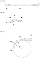
- FIG. 2A is an overall plan view of the spatula 80
- FIG. 2B is a plan view of the tip 81 of the spatula 80
- FIG. 2C is a side view of the tip 81 of the spatula 80.
- the spatula 80 is formed in a long rod shape or shaft shape as a whole.
- the tip 81 of the spatula 80 is formed in a curved plate shape, in other words, a spoon shape.
- the tip 81 has a shape in which a flat plate is curved with a substantially constant curvature, and is curved in a substantially arc shape in a side view.
- the arc book of the tip 81 in a side view is in the range of 1/8 arc to 1/4 arc.
- the tip 81 of the spatula 80 has a concave surface 82 and a convex surface 83 on the opposite side thereof.
- the tip 81 has a plate thickness s, the concave surface 82 is a curved surface with a radius R, the convex surface 83 is a curved surface with a radius R + s, and the concave surface 82 is substantially concentric with the convex surface 83. Since the curvature of the tip 81 is substantially constant, the concave surface 82 and the convex surface 83 constitute a part of a cylindrical surface.
- the shaping work is performed by sliding the convex surface 83 on the viscous material 95.
- the shaping work is performed once (or multiple times), the work of wiping the viscous material 95 attached to the tip 81 (particularly, the convex surface 83) of the spatula 80 with the sheet 96 is performed.
- the wiping device 1 automates this wiping work, and thereby, labor saving of the wiping work, which is a work incidental to the application work, is achieved.
- FIG. 3 is a conceptual diagram showing the wiping device 1.
- the sheet 96 used in the wiping device 1 is paper or cloth (including woven fabric and non-woven fabric), and may be dry or wet.
- the thickness p of the sheet 96 is approximately 40 to 300 ⁇ m.
- the wiping device 1 includes a sheet supply mechanism 2 and automates the supply of a clean sheet 96 before wiping and the discharge of the sheet 96 with the viscous material 95 by wiping.
- the sheet supply mechanism 2 includes a feed roller 3, a take-up roller 4, a roller actuator 5, and a power transmission mechanism 6.
- the two rollers 3 and 4 extend in parallel and are arranged at intervals.
- the feed roller 3 supports an upstream roll 96a around which the sheet 96 before wiping is wound.
- the take-up roller 4 supports a downstream roll 96b around which the sheet 96 after wiping is wound.
- a work area 99 where the viscous material 95 is wiped off is formed between the two rollers 3 and 4.
- the sheet 96 extends in a common circumscribed line direction of the two rolls 96a and 96b, and the two rolls 96a and 96b are composed of one long sheet 96.
- the roller actuator 5 is a power source for the two rollers 3 and 4 and is constituted by a single electric motor as an example.
- the power transmission mechanism 6 transmits the power generated by the roller actuator 5 to the two rollers 3 and 4 and rotationally drives the two rollers 3 and 4 in the same direction.
- the power transmission mechanism 6 may be configured in any way.
- the sheet 96 travels from the upstream roll 96a to the downstream roll 96b.
- the feed roller 3 rotates, and the clean sheet 96 is pulled out from the outer peripheral surface of the upstream roll 96a and supplied to the work area 99.
- the take-up roller 4 also rotates, and the sheet 96 with the viscous material 95 located in the work area 99 is wound around the downstream roll 96b to form the downstream roll 96b.
- the roller actuator 5 may be composed of two electric motors corresponding to the feed roller 3 and the take-up roller 4, respectively.
- a pair of belt transmission mechanisms are employed as the power transmission mechanism 6, the rotation of the roller actuator 5 is input to a driving pulley, and a driven pulley outputs the rotation to the roller 3 or the roller 4.
- the roller actuator 5 may be omitted, and a lever may be connected to the driving pulley. In this case, when a worker on the manufacturing site manually rotates the lever, the rollers 3 and 4 are rotationally driven, and the sheet 96 is supplied to and discharged from the work area.
- the wiping device 1 includes a sheet support jig 7, a spatula holding member 8, and a moving mechanism 9.
- the sheet support jig 7 is disposed in the work area 99.
- the sheet support jig 7 has a sheet facing surface 10 that faces the sheet 96 in the work area 99.
- the sheet support jig 7 is formed of an elastic body such as rubber.
- the sheet support jig 7 forms a hexahedron such as a rectangular parallelepiped, and the sheet facing surface 10 has a square or rectangular shape.
- the sheet facing surface 10 is horizontal, and the normal direction Z of the sheet facing surface 10 is vertical.
- the sheet facing surface 10 forms the upper surface of the sheet supporting jig 7, and the four surfaces that intersect the sheet facing surface 10 form the side surfaces of the sheet supporting jig 7.
- the sheet facing surface 10 is positioned below the sheet 96 in the work area 99.
- the sheet support jig 7 has a groove 11 recessed in the sheet facing surface 10.
- the groove 11 extends in a straight line on the sheet facing surface 10 while changing the groove width.
- the groove 11 is formed by a pair of inner side surfaces 12 and 13 and a bottom surface 14. The facing distance between the inner side surfaces 12 and 13 is the groove width.
- the groove 11 includes a receiving portion 15, a wiping portion 16, and a relief portion 17 that are continuous in a groove extending direction X.
- the wiping portion 16 has a smaller groove width than that of the receiving portion 15, and the relief portion 17 has a larger groove width than that of the wiping portion 16.
- the width direction of the groove 11 (hereinafter, "groove width direction Y") is a direction orthogonal to the groove extending direction X in the sheet facing surface 10 and is also orthogonal to the normal direction Z.
- the groove extending direction X is parallel to one side of the sheet facing surface 10.
- the groove 11 reaches the edge of the sheet facing surface 10 at both ends in the groove extending direction X, and is also open to the two side surfaces of the sheet supporting jig 7.
- FIG. 4A is a plan view of the sheet support jig 7, and FIG. 4B is a front view of the sheet support jig 7.
- the inner side surfaces 12 and 13 of the groove 11 are formed symmetrically with respect to the groove width center.
- the inner side surfaces 12 and 13 form curved inner side surfaces 12a and 13a that are curved with substantially the same curvature as the concave surface 82 of the spatula 80 when viewed in the normal direction Z at the portion where the wiping portion 16 is formed.
- the curved inner side surfaces 12a and 13a have an arc shape that protrudes inward each other in the groove width direction Y.
- the inner side surfaces 12 and 13 are inclined so that an angle formed with the sheet facing surface 10 forms an obtuse angle.
- the inner side surfaces 12 and 13 extend from the sheet facing surface 10 inclined inward in the groove width direction X with respect to the groove depth direction and intersect the bottom surface 14.
- the wiping portion 16 is similarly inclined, but an angle ⁇ 16 formed between the inner side surfaces 12 and 13 and the sheet facing surface 10 at the wiping portion 16 is greater than an angle ⁇ 15 formed between the inner side surfaces 12 and 13 and the sheet facing surface 10 at the receiving portion 15.
- the inner side surface 12 has a first portion 12b forming an angle with the sheet facing surface 10 and a second portion 12c continuous from the first portion, extending more steeply than the first portion, and forming an angle with the bottom surface 14.
- the length of the first portion 12b increases from the receiving portion 15 toward the wiping portion 16 in the groove extending direction X.
- the inclination of the second portion 12c becomes tighter from the receiving portion 15 toward the wiping portion 16 in the groove extending direction X. From the above, the groove width becomes narrower from the receiving portion 15 toward the wiping portion 16 in the groove extending direction X.
- the spatula holding member 8 includes a holding portion 21 that holds the base end portion of the spatula 80 and an attachment portion 22 that is detachably attached to the moving mechanism 9.
- the moving mechanism 9 moves the spatula holding member 8 and the spatula 80 held by this.
- the moving mechanism 9 is composed of a vertical articulated robot, and includes a robot arm 26 having a plurality of (for example, six) joints, and a plurality (the same number of joints) of moving actuators 27 (see FIG. 5 ) that respectively drive the plurality of joints.
- the attachment portion 22 of the spatula holding member 8 is detachably attached to the tip of the robot arm 26.
- the robot arm 26 of the moving mechanism 9 is operated, the spatula holding member 8 and the spatula 80 held by this move.
- the roller actuator 5 of the sheet supply mechanism 2 and the moving actuator 27 of the moving mechanism 9 are controlled by a controller 30.
- the controller 30 is, for example, a computer having a memory such as ROM and RAM and a CPU, and a program stored in the ROM is executed by the CPU.
- the controller 30 may be a single device or may be divided into a plurality of devices.
- the program stored in the ROM includes a program that teaches a moving locus and a moving speed of the tip of the robot arm 26, and by execution of the program (that is, playback), the spatula holding member 8 and the spatula 80 held by this can be moved as previously taught.
- the controller 30 is connected to an operation panel 31.
- the operation panel 31 is operated by a worker on the manufacturing site.
- the CPU of the controller 30 executes the above-described program, and position control and movement control of the spatula 80 are performed.
- the wiping work using the wiping device 1 having the above-described configuration starts when the command is input by the worker on the operation panel 31.
- the operation of the actuator described below is based on the control of the controller 30.
- the moving actuator 27 is actuated, and the posture of the robot arm 26 and the position and posture of the spatula 80 are changed.
- the spatula 80 is positioned on the opposite side of the sheet support jig 7 with respect to the sheet 96 in a posture that extends parallel to the groove extending direction X and overlaps the groove 11 when viewed in the normal direction of the sheet facing surface 10.
- the spatula 80 is positioned above the sheet 96.
- the "posture extending in parallel with the groove extending direction X when viewed in the normal direction” includes not only a posture in which the tip 81 of the spatula 80 extends in the sheet facing surface 10 (as an example, extending horizontally), but also a posture in which it is inclined in the normal direction Z (as an example, inclined up or down).
- the spatula 80 is moved to the side in which the spatula 80 approaches the sheet support jig 7 in the normal direction Z, the sheet 96 is pressed against the groove 11 with the spatula 80, and the tip 81 of the spatula 80 is received in the receiving portion.
- the concave surface 82 of the spatula 80 is in a posture facing one of the pair of inner side surfaces 12 and 13.
- the convex surface 83 of the spatula 80 takes a posture facing the other of the pair of inner side surfaces 12 and 13.
- the sheet 96 When the spatula 80 is received in the receiving portion 15, the sheet 96 is also pressed against the groove 11 together, and the sheet 96 is deformed into a substantially V shape. The tip 81 of the spatula is positioned inside the sheet 96 deformed into the V shape and is sandwiched between the sheets 96. Since the sheet 96 in the work area 99 is not tensioned and has a slight slack, even if it is made of paper, the sheet 96 is received in the groove 11 together with the spatula 80 without being torn.
- the sheet 96 can be prevented from being cut at an angle formed by the inner side surface and the sheet facing surface 10.
- the angle formed by the sheet facing surface 10 and the inner side surfaces 12 and 13 is relatively large, and the sheet 96 is particularly difficult to tear.
- the spatula 80 After the spatula 80 is received in the receiving portion, the spatula 80 is moved in the groove extending direction X. Thereby, the tip 81 of the spatula 80 approaches the wiping portion. Since the groove width gradually decreases, the convex surface 83 of the spatula 80 is brought close to the sheet 96, and the viscous material 95 adhering so as to rise on the convex surface 83 is wiped by the sheet 96 and removed from the spatula 80.
- the moving mechanism 9 allows the spatula 80 to pass through the wiping portion 16 by moving the spatula 80 in the groove extending direction X while maintaining the posture in which the spatula 80 extends in the groove extending direction X.
- the concave surface 82 of the spatula 80 reaches the curved inner side surface 12a of the wiping portion 16, the spatula 80 is later pulled out of the groove 11 so that the concave surface 82 of the spatula 80 is made to follow the curved inner side surface 12a.
- the spatula 80 is linearly moved substantially parallel to the longitudinal direction of the spatula 80 while the spatula 80 is rotated around the center of the curved inner side surface 12a.
- the spatula 80 can be pulled out of the groove 11 along the curved inner side surface 12a.
- the relief portion 17 continues from the wiping portion 16, the groove width of the relief portion 17 is wider than that of the wiping portion 16, and the end of the relief portion 17 is also open to the side surface of the sheet support jig 7. For this reason, even if the spatula 80 moves backward in the groove 11 while performing the combined motion of the rotational motion and the linear motion, the spatula 80 can be prevented from interfering with the sheet support jig 7.
- the groove width Wmin is smaller by a minute amount ds than the sum of the plate thickness s of the tip 81 of the spatula 80 and the thickness 2p of two sheets.
- the tip 81 of the spatula 80 is surrounded by the V-shaped sheet 96 when passing through the wiping portion 16.
- the minute amount ds is a value that is large enough to apply pressure from the sheet support jig 7 through the sheet 96 to the tip 81 of the spatula 80 that passes through the wiping portion 16, and is small enough to allow passage.
- the viscous material 95 attached to the convex surface 83 can be wiped off with the sheet 96 at the wiping portion 16. Therefore, labor of the work incidental to the application work of the viscous material 95 can be saved.
- the tip 81 of the spatula 80 is formed in a curved thin plate shape, even if the spatula 80 is moved in the groove extending direction X while keeping the posture of the spatula 80 in parallel with the groove extending direction X, the spatula 80 cannot pass through the wiping portion 16 or is remained on the convex surface 83 because pressure cannot be applied from the wiping portion to the entire area of the convex surface 83.
- the inner side surface at the wiping portion is a curved inner side surface that curves with the same curvature as the concave surface of the spatula 80, and the concave surface is moved so as to follow the inner side surface, the entire convex surface of the tip sequentially passes through the portion having the narrowest groove width in the wiping portion. Therefore, pressure can be applied to the entire convex surface from the wiping portion, and the viscous material 95 attached to the convex surface 83 can be wiped off well.
- the roller actuator 5 When wiping is performed once in this way, the roller actuator 5 is actuated, and the sheet 96 with the viscous material 95 in the work area 99 is wound around the take-up roller 4 to form the downstream roll 96b. A clean sheet is sent out from the upstream roll 96a to the work area 99. Thus, the groove 11 of the sheet support jig 7 is covered with the clean sheet 96, and preparation for the next wiping work is completed.
- the wiping portion 16 has a pair of curved inner side surfaces and has the same radius of curvature, but the radius of curvature may be different. As a result, the wiping work can be performed corresponding to the two spatulas 80 having different shapes of the tip 81. Further, only one of the inner side surfaces 12 and 13 in the wiping portion 16 may constitute the curved inner side surfaces 12a and 13a.
- the wiping device 1 may be configured to perform a shaping work.
- the shaping work and the wiping work are performed alternately.
Landscapes
- Coating Apparatus (AREA)
- Cleaning Implements For Floors, Carpets, Furniture, Walls, And The Like (AREA)
Claims (4)
- Wischvorrichtung (1) für viskoses Material zum Abwischen eines viskosen Materials (95), das an einer Spitze eines Spatels (80) anhaftet, wobei die Vorrichtung (1) konfiguriert ist, um ein Blatt (96) zum Durchführen des Wischens zu verwenden, wobei die Vorrichtung Folgendes umfasst:eine Blattträgervorrichtung (7) mit einer dem Blatt zugewandten Oberfläche (10), die zu dem Blatt zeigt, wenn es an der Vorrichtung (1) angewendet wird;ein Spatelhalteelement (8), das einen Basisendabschnitt des Spatels (80) hält und den Spatel freitragend trägt;einen Bewegungsmechanismus (9) zum Bewegen des Spatelhalteelements (8) zusammen mit dem Spatel (80); undeine Steuerung (30), wobeidie Blattträgervorrichtung (7) eine Nut (11) aufweist, die in der dem Blatt zugewandten Oberfläche (10) vertieft ist, wobei die Nut (11) einen Aufnahmeabschnitt (15) und einen Wischabschnitt (16) umfasst, die sich in einer Nuterstreckungsrichtung (X) aneinander anschließen, und wobei der Wischabschnitt (16) eine Nutbreite aufweist, die kleiner ist als die des Aufnahmeabschnitts (15) und im Wesentlichen gleich einer Außenabmessung der Spitze (81) des Spatels (80) ist, unddie Steuerung (30) so konfiguriert ist, dass sie den Bewegungsmechanismus (9) zu Folgendem antreibt:Positionieren des Spatels (80) auf der gegenüberliegenden Seite der Blattträgervorrichtung (7) in Bezug auf das Blatt (96) in einer solchen Stellung, dass der Spatel (80) sich parallel zu der Nuterstreckungsrichtung (X) erstreckt und bei Betrachtung in einer Normalenrichtung (Z) der dem Blatt zugewandten Oberfläche (10) die Nut (11) überlappt,Bewegen des Spatels (80) in der Normalenrichtung (Z), so dass die Spitze (81) des Spatels (80) in dem Aufnahmeabschnitt (15) aufgenommen wird, indem das Blatt (96) mit dem Spatel (80) gegen die Nut (11) gedrückt wird, undBewegen des Spatels (80) in der Nuterstreckungsrichtung (X), so dass die Spitze (81) des Spatels (80) durch den Wischabschnitt (16) geht.
- Wischvorrichtung für viskoses Material nach Anspruch 1, wobei:die Spitze (81) des Spatels (80) in Form einer gekrümmten Platte ausgebildet ist und eine konkave Oberfläche (82) und eine konvexe Oberfläche (83) auf der gegenüberliegenden Seite davon aufweist;zumindest eine aus einem Paar von inneren Seitenflächen (12, 13) der Nut (11) eine gekrümmte innere Seitenfläche (12a, 13a) bildet, die mit im Wesentlichen der gleichen Krümmung wie die konkave Fläche (82) gekrümmt ist, wenn sie in der Normalenrichtung (Z) in einem Abschnitt betrachtet wird, der den Wischabschnitt (16) bildet; unddie Steuerung (30) zu Folgendem konfiguriert ist:Bewegen des Spatels (80) in der Normalenrichtung (Z), so dass die Spitze (81) in dem Aufnahmeabschnitt (15) in einer Stellung aufgenommen wird, in der die konkave Oberfläche (82) der inneren Seitenfläche (12, 13) der Nut (11) zugewandt ist, undin einem Prozess des Bewegens des Spatels (80) in der Nuterstreckungsrichtung (X), nachdem die konkave Oberfläche (82) beginnt, der gekrümmten inneren Seitenfläche (12a, 13a) zugewandt zu sein, Bewegen des Spatels (80) in der Nuterstreckungsrichtung (X), während der Spatel (80) drehend bewegt wird, so dass die konkave Oberfläche (82) der gekrümmten inneren Seitenfläche (12a, 13a) folgt.
- Wischvorrichtung für viskoses Material nach Anspruch 1 oder 2, wobei die Nut (11) einen Aussparungsabschnitt (17) umfasst, der sich an den Wischabschnitt (16) in der Nuterstreckungsrichtung (X) anschließt, und der Aussparungsabschnitt (17) eine größere Nutbreite als die des Wischabschnitts (16) aufweist.
- Wischvorrichtung für viskoses Material nach einem der Ansprüche 1 bis 3, wobei das Paar von inneren Seitenflächen (12, 13) der Nut (11) derart geneigt ist, dass ein mit der dem Blatt zugewandten Fläche (10) gebildeter Winkel einen stumpfen Winkel bildet.
Applications Claiming Priority (2)
| Application Number | Priority Date | Filing Date | Title |
|---|---|---|---|
| JP2017170838A JP6767951B2 (ja) | 2017-09-06 | 2017-09-06 | 粘性材料拭き取り装置 |
| PCT/JP2018/032666 WO2019049840A1 (ja) | 2017-09-06 | 2018-09-03 | 粘性材料拭き取り装置 |
Publications (3)
| Publication Number | Publication Date |
|---|---|
| EP3680025A1 EP3680025A1 (de) | 2020-07-15 |
| EP3680025A4 EP3680025A4 (de) | 2021-01-06 |
| EP3680025B1 true EP3680025B1 (de) | 2022-04-13 |
Family
ID=65633977
Family Applications (1)
| Application Number | Title | Priority Date | Filing Date |
|---|---|---|---|
| EP18853808.6A Active EP3680025B1 (de) | 2017-09-06 | 2018-09-03 | Wischvorrichtung aus viskosem material |
Country Status (4)
| Country | Link |
|---|---|
| US (1) | US11311902B2 (de) |
| EP (1) | EP3680025B1 (de) |
| JP (1) | JP6767951B2 (de) |
| WO (1) | WO2019049840A1 (de) |
Families Citing this family (1)
| Publication number | Priority date | Publication date | Assignee | Title |
|---|---|---|---|---|
| JP7057898B2 (ja) * | 2018-07-25 | 2022-04-21 | トヨタ自動車九州株式会社 | ヘラ体付着シーラ除去装置 |
Family Cites Families (13)
| Publication number | Priority date | Publication date | Assignee | Title |
|---|---|---|---|---|
| JPH06269720A (ja) | 1993-03-19 | 1994-09-27 | Toyota Motor Corp | 粘性材料塗布装置 |
| JP3112813U (ja) * | 2005-05-25 | 2005-08-25 | 株式会社アルファー技研 | 洗浄装置 |
| JP2007245136A (ja) * | 2006-02-17 | 2007-09-27 | Seiko Epson Corp | 液滴吐出装置、液滴吐出ヘッドの回復方法、薄膜の形成方法、配向膜の形成方法、配向膜形成用液滴吐出ヘッドの回復方法、配向膜形成装置及び液晶表示装置 |
| JP5071167B2 (ja) * | 2007-03-27 | 2012-11-14 | 東レ株式会社 | 清掃部材と塗布器の清掃方法および清掃装置並びにディスプレイ用部材の製造方法 |
| JP4241863B2 (ja) * | 2007-08-08 | 2009-03-18 | トヨタ自動車株式会社 | シーラ仕上げ用へらの清掃装置 |
| JP5841449B2 (ja) * | 2012-02-10 | 2016-01-13 | 東京エレクトロン株式会社 | 拭き取りパッド及びこのパッドを用いたノズルメンテナンス装置並びに塗布処理装置 |
| CN103364252B (zh) * | 2012-04-10 | 2017-01-18 | 深圳迈瑞生物医疗电子股份有限公司 | 推片染色机的涂片推片洁净方法及装置 |
| CN103962319B (zh) * | 2014-04-03 | 2016-08-17 | 华为技术有限公司 | 擦拭机构及具有擦拭机构的自动清洗装置 |
| JP6526947B2 (ja) * | 2014-04-30 | 2019-06-05 | 株式会社半導体エネルギー研究所 | 拭き取り装置および積層体の作製装置 |
| JP6697228B2 (ja) * | 2015-06-25 | 2020-05-20 | 株式会社Subaru | シーラント整形装置及びシーラント塗布製品の製造方法 |
| JP6766168B2 (ja) * | 2016-11-02 | 2020-10-07 | 株式会社瑞光 | シート繰出システムおよびシート繰出方法 |
| US10350895B2 (en) * | 2017-03-15 | 2019-07-16 | Ricoh Company, Ltd. | Head cleaner and liquid discharge apparatus |
| US10759173B2 (en) * | 2018-05-30 | 2020-09-01 | Ricoh Company, Ltd. | Wiping member, wiping method, and wiping device |
-
2017
- 2017-09-06 JP JP2017170838A patent/JP6767951B2/ja active Active
-
2018
- 2018-09-03 EP EP18853808.6A patent/EP3680025B1/de active Active
- 2018-09-03 WO PCT/JP2018/032666 patent/WO2019049840A1/ja not_active Ceased
-
2020
- 2020-03-06 US US16/810,862 patent/US11311902B2/en active Active
Also Published As
| Publication number | Publication date |
|---|---|
| US11311902B2 (en) | 2022-04-26 |
| US20200206772A1 (en) | 2020-07-02 |
| EP3680025A1 (de) | 2020-07-15 |
| JP6767951B2 (ja) | 2020-10-14 |
| EP3680025A4 (de) | 2021-01-06 |
| WO2019049840A1 (ja) | 2019-03-14 |
| JP2019042706A (ja) | 2019-03-22 |
Similar Documents
| Publication | Publication Date | Title |
|---|---|---|
| CN109996748B (zh) | 片体送出系统及片体送出方法 | |
| EP3680025B1 (de) | Wischvorrichtung aus viskosem material | |
| HUP0200743A2 (en) | Production for disposable dirt wiping-out implement | |
| TW202021815A (zh) | 擦除裝置以及擦除方法 | |
| JP2019531951A (ja) | フィルム貼付装置及びフィルム貼付方法 | |
| JP2002515334A (ja) | 表面処理装置 | |
| CA2546432A1 (en) | Dosing device, apparatus for applying adhesives to at least one dosing device, and substrate web | |
| KR101862996B1 (ko) | 방수 시공 장치 | |
| KR100439549B1 (ko) | 캐빈카트리지필터의 제조방법 및 바인딩장치 | |
| JP2025033710A (ja) | テープ材の貼付装置 | |
| KR100205092B1 (ko) | 접착시트의 접착제도포장치 | |
| JP7657503B1 (ja) | テープ材の貼付装置 | |
| ITMO20090128A1 (it) | Metodo per sagomare una superficie di un oggetto e apparato sagomatore | |
| JP5075081B2 (ja) | アスベスト含有建材剥離装置 | |
| WO2015151435A1 (ja) | 帯状部材の巻付け方法および装置 | |
| IT201800010551A1 (it) | Metodo e dispositivo di spalmatura | |
| JP5079719B2 (ja) | 乗客用コンベアのステップ清掃装置 | |
| JP5205808B2 (ja) | 溝付板材の溝塗装装置 | |
| SU1609630A1 (ru) | Устройство дл изготовлени заготовки бесконечной абразивной ленты | |
| JP6834567B2 (ja) | タイルユニットの製造方法、接着剤塗布器具、およびタイルユニットの製造装置 | |
| JP2026512111A5 (de) | ||
| KR20260025189A (ko) | 조선해양산업 저숙련자 용접 효율성 향상을 위한 용접 지원장비 | |
| JP2025173769A (ja) | テープ材貼付けシステムおよびコンピュータプログラム | |
| JP2023084869A (ja) | 化粧製品製造装置、及び表面処理方法 | |
| CN103228421A (zh) | 马海毛插入装置 |
Legal Events
| Date | Code | Title | Description |
|---|---|---|---|
| STAA | Information on the status of an ep patent application or granted ep patent |
Free format text: STATUS: THE INTERNATIONAL PUBLICATION HAS BEEN MADE |
|
| PUAI | Public reference made under article 153(3) epc to a published international application that has entered the european phase |
Free format text: ORIGINAL CODE: 0009012 |
|
| STAA | Information on the status of an ep patent application or granted ep patent |
Free format text: STATUS: REQUEST FOR EXAMINATION WAS MADE |
|
| 17P | Request for examination filed |
Effective date: 20200311 |
|
| AK | Designated contracting states |
Kind code of ref document: A1 Designated state(s): AL AT BE BG CH CY CZ DE DK EE ES FI FR GB GR HR HU IE IS IT LI LT LU LV MC MK MT NL NO PL PT RO RS SE SI SK SM TR |
|
| AX | Request for extension of the european patent |
Extension state: BA ME |
|
| DAV | Request for validation of the european patent (deleted) | ||
| DAX | Request for extension of the european patent (deleted) | ||
| A4 | Supplementary search report drawn up and despatched |
Effective date: 20201208 |
|
| RIC1 | Information provided on ipc code assigned before grant |
Ipc: B05C 11/02 20060101ALI20201202BHEP Ipc: B05C 11/10 20060101ALI20201202BHEP Ipc: B08B 1/00 20060101AFI20201202BHEP |
|
| REG | Reference to a national code |
Ref country code: DE Ref legal event code: R079 Ref document number: 602018033936 Country of ref document: DE Free format text: PREVIOUS MAIN CLASS: B05C0011100000 Ipc: B08B0001000000 |
|
| RIC1 | Information provided on ipc code assigned before grant |
Ipc: B05C 11/02 20060101ALI20210831BHEP Ipc: B05C 11/10 20060101ALI20210831BHEP Ipc: B08B 1/00 20060101AFI20210831BHEP |
|
| GRAP | Despatch of communication of intention to grant a patent |
Free format text: ORIGINAL CODE: EPIDOSNIGR1 |
|
| STAA | Information on the status of an ep patent application or granted ep patent |
Free format text: STATUS: GRANT OF PATENT IS INTENDED |
|
| INTG | Intention to grant announced |
Effective date: 20211026 |
|
| GRAS | Grant fee paid |
Free format text: ORIGINAL CODE: EPIDOSNIGR3 |
|
| GRAA | (expected) grant |
Free format text: ORIGINAL CODE: 0009210 |
|
| STAA | Information on the status of an ep patent application or granted ep patent |
Free format text: STATUS: THE PATENT HAS BEEN GRANTED |
|
| AK | Designated contracting states |
Kind code of ref document: B1 Designated state(s): AL AT BE BG CH CY CZ DE DK EE ES FI FR GB GR HR HU IE IS IT LI LT LU LV MC MK MT NL NO PL PT RO RS SE SI SK SM TR |
|
| REG | Reference to a national code |
Ref country code: GB Ref legal event code: FG4D |
|
| REG | Reference to a national code |
Ref country code: CH Ref legal event code: EP |
|
| REG | Reference to a national code |
Ref country code: DE Ref legal event code: R096 Ref document number: 602018033936 Country of ref document: DE |
|
| REG | Reference to a national code |
Ref country code: IE Ref legal event code: FG4D |
|
| REG | Reference to a national code |
Ref country code: AT Ref legal event code: REF Ref document number: 1482991 Country of ref document: AT Kind code of ref document: T Effective date: 20220515 |
|
| REG | Reference to a national code |
Ref country code: LT Ref legal event code: MG9D |
|
| REG | Reference to a national code |
Ref country code: NL Ref legal event code: MP Effective date: 20220413 |
|
| REG | Reference to a national code |
Ref country code: AT Ref legal event code: MK05 Ref document number: 1482991 Country of ref document: AT Kind code of ref document: T Effective date: 20220413 |
|
| PG25 | Lapsed in a contracting state [announced via postgrant information from national office to epo] |
Ref country code: NL Free format text: LAPSE BECAUSE OF FAILURE TO SUBMIT A TRANSLATION OF THE DESCRIPTION OR TO PAY THE FEE WITHIN THE PRESCRIBED TIME-LIMIT Effective date: 20220413 |
|
| PG25 | Lapsed in a contracting state [announced via postgrant information from national office to epo] |
Ref country code: SE Free format text: LAPSE BECAUSE OF FAILURE TO SUBMIT A TRANSLATION OF THE DESCRIPTION OR TO PAY THE FEE WITHIN THE PRESCRIBED TIME-LIMIT Effective date: 20220413 Ref country code: PT Free format text: LAPSE BECAUSE OF FAILURE TO SUBMIT A TRANSLATION OF THE DESCRIPTION OR TO PAY THE FEE WITHIN THE PRESCRIBED TIME-LIMIT Effective date: 20220816 Ref country code: NO Free format text: LAPSE BECAUSE OF FAILURE TO SUBMIT A TRANSLATION OF THE DESCRIPTION OR TO PAY THE FEE WITHIN THE PRESCRIBED TIME-LIMIT Effective date: 20220713 Ref country code: LT Free format text: LAPSE BECAUSE OF FAILURE TO SUBMIT A TRANSLATION OF THE DESCRIPTION OR TO PAY THE FEE WITHIN THE PRESCRIBED TIME-LIMIT Effective date: 20220413 Ref country code: HR Free format text: LAPSE BECAUSE OF FAILURE TO SUBMIT A TRANSLATION OF THE DESCRIPTION OR TO PAY THE FEE WITHIN THE PRESCRIBED TIME-LIMIT Effective date: 20220413 Ref country code: GR Free format text: LAPSE BECAUSE OF FAILURE TO SUBMIT A TRANSLATION OF THE DESCRIPTION OR TO PAY THE FEE WITHIN THE PRESCRIBED TIME-LIMIT Effective date: 20220714 Ref country code: FI Free format text: LAPSE BECAUSE OF FAILURE TO SUBMIT A TRANSLATION OF THE DESCRIPTION OR TO PAY THE FEE WITHIN THE PRESCRIBED TIME-LIMIT Effective date: 20220413 Ref country code: ES Free format text: LAPSE BECAUSE OF FAILURE TO SUBMIT A TRANSLATION OF THE DESCRIPTION OR TO PAY THE FEE WITHIN THE PRESCRIBED TIME-LIMIT Effective date: 20220413 Ref country code: BG Free format text: LAPSE BECAUSE OF FAILURE TO SUBMIT A TRANSLATION OF THE DESCRIPTION OR TO PAY THE FEE WITHIN THE PRESCRIBED TIME-LIMIT Effective date: 20220713 Ref country code: AT Free format text: LAPSE BECAUSE OF FAILURE TO SUBMIT A TRANSLATION OF THE DESCRIPTION OR TO PAY THE FEE WITHIN THE PRESCRIBED TIME-LIMIT Effective date: 20220413 |
|
| PG25 | Lapsed in a contracting state [announced via postgrant information from national office to epo] |
Ref country code: RS Free format text: LAPSE BECAUSE OF FAILURE TO SUBMIT A TRANSLATION OF THE DESCRIPTION OR TO PAY THE FEE WITHIN THE PRESCRIBED TIME-LIMIT Effective date: 20220413 Ref country code: PL Free format text: LAPSE BECAUSE OF FAILURE TO SUBMIT A TRANSLATION OF THE DESCRIPTION OR TO PAY THE FEE WITHIN THE PRESCRIBED TIME-LIMIT Effective date: 20220413 Ref country code: LV Free format text: LAPSE BECAUSE OF FAILURE TO SUBMIT A TRANSLATION OF THE DESCRIPTION OR TO PAY THE FEE WITHIN THE PRESCRIBED TIME-LIMIT Effective date: 20220413 Ref country code: IS Free format text: LAPSE BECAUSE OF FAILURE TO SUBMIT A TRANSLATION OF THE DESCRIPTION OR TO PAY THE FEE WITHIN THE PRESCRIBED TIME-LIMIT Effective date: 20220813 |
|
| REG | Reference to a national code |
Ref country code: DE Ref legal event code: R097 Ref document number: 602018033936 Country of ref document: DE |
|
| PG25 | Lapsed in a contracting state [announced via postgrant information from national office to epo] |
Ref country code: SM Free format text: LAPSE BECAUSE OF FAILURE TO SUBMIT A TRANSLATION OF THE DESCRIPTION OR TO PAY THE FEE WITHIN THE PRESCRIBED TIME-LIMIT Effective date: 20220413 Ref country code: SK Free format text: LAPSE BECAUSE OF FAILURE TO SUBMIT A TRANSLATION OF THE DESCRIPTION OR TO PAY THE FEE WITHIN THE PRESCRIBED TIME-LIMIT Effective date: 20220413 Ref country code: RO Free format text: LAPSE BECAUSE OF FAILURE TO SUBMIT A TRANSLATION OF THE DESCRIPTION OR TO PAY THE FEE WITHIN THE PRESCRIBED TIME-LIMIT Effective date: 20220413 Ref country code: EE Free format text: LAPSE BECAUSE OF FAILURE TO SUBMIT A TRANSLATION OF THE DESCRIPTION OR TO PAY THE FEE WITHIN THE PRESCRIBED TIME-LIMIT Effective date: 20220413 Ref country code: DK Free format text: LAPSE BECAUSE OF FAILURE TO SUBMIT A TRANSLATION OF THE DESCRIPTION OR TO PAY THE FEE WITHIN THE PRESCRIBED TIME-LIMIT Effective date: 20220413 Ref country code: CZ Free format text: LAPSE BECAUSE OF FAILURE TO SUBMIT A TRANSLATION OF THE DESCRIPTION OR TO PAY THE FEE WITHIN THE PRESCRIBED TIME-LIMIT Effective date: 20220413 |
|
| PLBE | No opposition filed within time limit |
Free format text: ORIGINAL CODE: 0009261 |
|
| STAA | Information on the status of an ep patent application or granted ep patent |
Free format text: STATUS: NO OPPOSITION FILED WITHIN TIME LIMIT |
|
| 26N | No opposition filed |
Effective date: 20230116 |
|
| PG25 | Lapsed in a contracting state [announced via postgrant information from national office to epo] |
Ref country code: AL Free format text: LAPSE BECAUSE OF FAILURE TO SUBMIT A TRANSLATION OF THE DESCRIPTION OR TO PAY THE FEE WITHIN THE PRESCRIBED TIME-LIMIT Effective date: 20220413 |
|
| PG25 | Lapsed in a contracting state [announced via postgrant information from national office to epo] |
Ref country code: MC Free format text: LAPSE BECAUSE OF FAILURE TO SUBMIT A TRANSLATION OF THE DESCRIPTION OR TO PAY THE FEE WITHIN THE PRESCRIBED TIME-LIMIT Effective date: 20220413 |
|
| REG | Reference to a national code |
Ref country code: CH Ref legal event code: PL |
|
| GBPC | Gb: european patent ceased through non-payment of renewal fee |
Effective date: 20220903 |
|
| REG | Reference to a national code |
Ref country code: BE Ref legal event code: MM Effective date: 20220930 |
|
| PG25 | Lapsed in a contracting state [announced via postgrant information from national office to epo] |
Ref country code: SI Free format text: LAPSE BECAUSE OF FAILURE TO SUBMIT A TRANSLATION OF THE DESCRIPTION OR TO PAY THE FEE WITHIN THE PRESCRIBED TIME-LIMIT Effective date: 20220413 |
|
| PG25 | Lapsed in a contracting state [announced via postgrant information from national office to epo] |
Ref country code: LU Free format text: LAPSE BECAUSE OF NON-PAYMENT OF DUE FEES Effective date: 20220903 |
|
| PG25 | Lapsed in a contracting state [announced via postgrant information from national office to epo] |
Ref country code: LI Free format text: LAPSE BECAUSE OF NON-PAYMENT OF DUE FEES Effective date: 20220930 Ref country code: IE Free format text: LAPSE BECAUSE OF NON-PAYMENT OF DUE FEES Effective date: 20220903 Ref country code: CH Free format text: LAPSE BECAUSE OF NON-PAYMENT OF DUE FEES Effective date: 20220930 |
|
| PG25 | Lapsed in a contracting state [announced via postgrant information from national office to epo] |
Ref country code: BE Free format text: LAPSE BECAUSE OF NON-PAYMENT OF DUE FEES Effective date: 20220930 |
|
| PG25 | Lapsed in a contracting state [announced via postgrant information from national office to epo] |
Ref country code: GB Free format text: LAPSE BECAUSE OF NON-PAYMENT OF DUE FEES Effective date: 20220903 |
|
| PG25 | Lapsed in a contracting state [announced via postgrant information from national office to epo] |
Ref country code: IT Free format text: LAPSE BECAUSE OF FAILURE TO SUBMIT A TRANSLATION OF THE DESCRIPTION OR TO PAY THE FEE WITHIN THE PRESCRIBED TIME-LIMIT Effective date: 20220413 |
|
| PG25 | Lapsed in a contracting state [announced via postgrant information from national office to epo] |
Ref country code: CY Free format text: LAPSE BECAUSE OF FAILURE TO SUBMIT A TRANSLATION OF THE DESCRIPTION OR TO PAY THE FEE WITHIN THE PRESCRIBED TIME-LIMIT Effective date: 20220413 |
|
| PG25 | Lapsed in a contracting state [announced via postgrant information from national office to epo] |
Ref country code: MK Free format text: LAPSE BECAUSE OF FAILURE TO SUBMIT A TRANSLATION OF THE DESCRIPTION OR TO PAY THE FEE WITHIN THE PRESCRIBED TIME-LIMIT Effective date: 20220413 Ref country code: HU Free format text: LAPSE BECAUSE OF FAILURE TO SUBMIT A TRANSLATION OF THE DESCRIPTION OR TO PAY THE FEE WITHIN THE PRESCRIBED TIME-LIMIT; INVALID AB INITIO Effective date: 20180903 |
|
| PG25 | Lapsed in a contracting state [announced via postgrant information from national office to epo] |
Ref country code: MT Free format text: LAPSE BECAUSE OF FAILURE TO SUBMIT A TRANSLATION OF THE DESCRIPTION OR TO PAY THE FEE WITHIN THE PRESCRIBED TIME-LIMIT Effective date: 20220413 |
|
| PG25 | Lapsed in a contracting state [announced via postgrant information from national office to epo] |
Ref country code: BG Free format text: LAPSE BECAUSE OF FAILURE TO SUBMIT A TRANSLATION OF THE DESCRIPTION OR TO PAY THE FEE WITHIN THE PRESCRIBED TIME-LIMIT Effective date: 20220413 |
|
| PG25 | Lapsed in a contracting state [announced via postgrant information from national office to epo] |
Ref country code: BG Free format text: LAPSE BECAUSE OF FAILURE TO SUBMIT A TRANSLATION OF THE DESCRIPTION OR TO PAY THE FEE WITHIN THE PRESCRIBED TIME-LIMIT Effective date: 20220413 |
|
| PGFP | Annual fee paid to national office [announced via postgrant information from national office to epo] |
Ref country code: DE Payment date: 20250730 Year of fee payment: 8 |
|
| PGFP | Annual fee paid to national office [announced via postgrant information from national office to epo] |
Ref country code: FR Payment date: 20250808 Year of fee payment: 8 |
|
| PG25 | Lapsed in a contracting state [announced via postgrant information from national office to epo] |
Ref country code: TR Free format text: LAPSE BECAUSE OF FAILURE TO SUBMIT A TRANSLATION OF THE DESCRIPTION OR TO PAY THE FEE WITHIN THE PRESCRIBED TIME-LIMIT Effective date: 20220413 |