EP3679976A1 - Katheter - Google Patents
Katheter Download PDFInfo
- Publication number
- EP3679976A1 EP3679976A1 EP18854968.7A EP18854968A EP3679976A1 EP 3679976 A1 EP3679976 A1 EP 3679976A1 EP 18854968 A EP18854968 A EP 18854968A EP 3679976 A1 EP3679976 A1 EP 3679976A1
- Authority
- EP
- European Patent Office
- Prior art keywords
- chamber
- temperature
- balloon
- catheter
- sheet
- Prior art date
- Legal status (The legal status is an assumption and is not a legal conclusion. Google has not performed a legal analysis and makes no representation as to the accuracy of the status listed.)
- Withdrawn
Links
Images


Classifications
-
- A—HUMAN NECESSITIES
- A61—MEDICAL OR VETERINARY SCIENCE; HYGIENE
- A61B—DIAGNOSIS; SURGERY; IDENTIFICATION
- A61B5/00—Measuring for diagnostic purposes; Identification of persons
- A61B5/68—Arrangements of detecting, measuring or recording means, e.g. sensors, in relation to patient
- A61B5/6846—Arrangements of detecting, measuring or recording means, e.g. sensors, in relation to patient specially adapted to be brought in contact with an internal body part, i.e. invasive
- A61B5/6847—Arrangements of detecting, measuring or recording means, e.g. sensors, in relation to patient specially adapted to be brought in contact with an internal body part, i.e. invasive mounted on an invasive device
- A61B5/6852—Catheters
- A61B5/6853—Catheters with a balloon
-
- A—HUMAN NECESSITIES
- A61—MEDICAL OR VETERINARY SCIENCE; HYGIENE
- A61B—DIAGNOSIS; SURGERY; IDENTIFICATION
- A61B18/00—Surgical instruments, devices or methods for transferring non-mechanical forms of energy to or from the body
- A61B18/04—Surgical instruments, devices or methods for transferring non-mechanical forms of energy to or from the body by heating
- A61B18/12—Surgical instruments, devices or methods for transferring non-mechanical forms of energy to or from the body by heating by passing a current through the tissue to be heated, e.g. high-frequency current
- A61B18/14—Probes or electrodes therefor
- A61B18/1492—Probes or electrodes therefor having a flexible, catheter-like structure, e.g. for heart ablation
-
- A—HUMAN NECESSITIES
- A61—MEDICAL OR VETERINARY SCIENCE; HYGIENE
- A61B—DIAGNOSIS; SURGERY; IDENTIFICATION
- A61B5/00—Measuring for diagnostic purposes; Identification of persons
- A61B5/01—Measuring temperature of body parts ; Diagnostic temperature sensing, e.g. for malignant or inflamed tissue
- A61B5/015—By temperature mapping of body part
-
- A—HUMAN NECESSITIES
- A61—MEDICAL OR VETERINARY SCIENCE; HYGIENE
- A61B—DIAGNOSIS; SURGERY; IDENTIFICATION
- A61B5/00—Measuring for diagnostic purposes; Identification of persons
- A61B5/68—Arrangements of detecting, measuring or recording means, e.g. sensors, in relation to patient
- A61B5/6846—Arrangements of detecting, measuring or recording means, e.g. sensors, in relation to patient specially adapted to be brought in contact with an internal body part, i.e. invasive
- A61B5/6867—Arrangements of detecting, measuring or recording means, e.g. sensors, in relation to patient specially adapted to be brought in contact with an internal body part, i.e. invasive specially adapted to be attached or implanted in a specific body part
- A61B5/687—Oesophagus
-
- A—HUMAN NECESSITIES
- A61—MEDICAL OR VETERINARY SCIENCE; HYGIENE
- A61B—DIAGNOSIS; SURGERY; IDENTIFICATION
- A61B90/00—Instruments, implements or accessories specially adapted for surgery or diagnosis and not covered by any of the groups A61B1/00 - A61B50/00, e.g. for luxation treatment or for protecting wound edges
- A61B90/04—Protection of tissue around surgical sites against effects of non-mechanical surgery, e.g. laser surgery
-
- A—HUMAN NECESSITIES
- A61—MEDICAL OR VETERINARY SCIENCE; HYGIENE
- A61M—DEVICES FOR INTRODUCING MEDIA INTO, OR ONTO, THE BODY; DEVICES FOR TRANSDUCING BODY MEDIA OR FOR TAKING MEDIA FROM THE BODY; DEVICES FOR PRODUCING OR ENDING SLEEP OR STUPOR
- A61M25/00—Catheters; Hollow probes
- A61M25/10—Balloon catheters
-
- A—HUMAN NECESSITIES
- A61—MEDICAL OR VETERINARY SCIENCE; HYGIENE
- A61B—DIAGNOSIS; SURGERY; IDENTIFICATION
- A61B18/00—Surgical instruments, devices or methods for transferring non-mechanical forms of energy to or from the body
- A61B2018/00315—Surgical instruments, devices or methods for transferring non-mechanical forms of energy to or from the body for treatment of particular body parts
- A61B2018/00345—Vascular system
- A61B2018/00351—Heart
-
- A—HUMAN NECESSITIES
- A61—MEDICAL OR VETERINARY SCIENCE; HYGIENE
- A61B—DIAGNOSIS; SURGERY; IDENTIFICATION
- A61B18/00—Surgical instruments, devices or methods for transferring non-mechanical forms of energy to or from the body
- A61B2018/00315—Surgical instruments, devices or methods for transferring non-mechanical forms of energy to or from the body for treatment of particular body parts
- A61B2018/00482—Digestive system
- A61B2018/00488—Esophagus
-
- A—HUMAN NECESSITIES
- A61—MEDICAL OR VETERINARY SCIENCE; HYGIENE
- A61B—DIAGNOSIS; SURGERY; IDENTIFICATION
- A61B18/00—Surgical instruments, devices or methods for transferring non-mechanical forms of energy to or from the body
- A61B2018/00571—Surgical instruments, devices or methods for transferring non-mechanical forms of energy to or from the body for achieving a particular surgical effect
- A61B2018/00577—Ablation
-
- A—HUMAN NECESSITIES
- A61—MEDICAL OR VETERINARY SCIENCE; HYGIENE
- A61B—DIAGNOSIS; SURGERY; IDENTIFICATION
- A61B18/00—Surgical instruments, devices or methods for transferring non-mechanical forms of energy to or from the body
- A61B2018/00636—Sensing and controlling the application of energy
- A61B2018/00773—Sensed parameters
- A61B2018/00791—Temperature
- A61B2018/00797—Temperature measured by multiple temperature sensors
-
- A—HUMAN NECESSITIES
- A61—MEDICAL OR VETERINARY SCIENCE; HYGIENE
- A61B—DIAGNOSIS; SURGERY; IDENTIFICATION
- A61B2562/00—Details of sensors; Constructional details of sensor housings or probes; Accessories for sensors
- A61B2562/04—Arrangements of multiple sensors of the same type
- A61B2562/043—Arrangements of multiple sensors of the same type in a linear array
-
- A—HUMAN NECESSITIES
- A61—MEDICAL OR VETERINARY SCIENCE; HYGIENE
- A61M—DEVICES FOR INTRODUCING MEDIA INTO, OR ONTO, THE BODY; DEVICES FOR TRANSDUCING BODY MEDIA OR FOR TAKING MEDIA FROM THE BODY; DEVICES FOR PRODUCING OR ENDING SLEEP OR STUPOR
- A61M2205/00—General characteristics of the apparatus
- A61M2205/33—Controlling, regulating or measuring
- A61M2205/3368—Temperature
-
- A—HUMAN NECESSITIES
- A61—MEDICAL OR VETERINARY SCIENCE; HYGIENE
- A61M—DEVICES FOR INTRODUCING MEDIA INTO, OR ONTO, THE BODY; DEVICES FOR TRANSDUCING BODY MEDIA OR FOR TAKING MEDIA FROM THE BODY; DEVICES FOR PRODUCING OR ENDING SLEEP OR STUPOR
- A61M2230/00—Measuring parameters of the user
- A61M2230/50—Temperature
Definitions
- the present invention relates to a catheter to be used for measuring an internal temperature of a hollow organ, such as an esophagus, in a body.
- an electrode catheter esophagus catheter
- a plurality of ring-shaped electrodes electrodes for temperature measurement
- a plurality of temperature sensors electrically connected to the ring-shaped electrode by being spot-welded to respective inner circumferential surfaces of these ring-shaped electrodes
- respective lead wires specifically, metal wires of different types constituting the thermocouple
- a plurality of side holes are formed and arranged in a tube wall of the distal end portion of the catheter shaft constituting such an esophagus catheter in correspondence to positions at which the ring-shaped electrodes are mounted.
- the lead wires spot-welded to the inner circumferential surface of the ring-shaped electrodes and connected to the temperature sensors enter a lumen from the side holes formed in the tube wall of the catheter shaft, extend in the lumen and an inner portion of a control handle, and is connected to a connector.
- the esophagus usually has a flat elliptical tube shape, and the internal temperature of the esophagus during an ablation operation of a left atrium is distributed not only in the length direction of the esophagus but also in the width direction thereof.
- the plurality of ring-shaped electrodes are disposed in the length direction of the esophagus, and it is thus not possible to measure the temperature distribution in the width direction of the esophagus.
- a temperature probe for monitoring the temperature of tissues in a body or a surface of an organ there is proposed a probe including: a distal end part deformable into a meandering shape, in other words, a shaft having a deformable section that memorizes a shape meandering on a same plane; and a plurality of temperature sensors (ring-shaped electrodes) mounted at the distal end part of the shaft (refer to PTL 2 presented below).
- such a temperature probe is also not capable of precisely measuring the temperature distribution in an esophagus in the width direction.
- the plurality of temperature sensors are disposed planarly (dispersed in a substantially two-dimensional arrangement) when the distal end part of the shaft having the meandering shape is left in an esophagus, and, however, an arrangement interval of the temperature sensors is wide.
- the temperature sensors adjacent to each other are away from each other not only in the width direction of the esophagus but also in the length direction of the esophagus.
- a temperature probe such as that described in PTL 2 may increase a risk of the esophagus being overheated as a result of the distal end part expanding the esophagus and increasing a contact area with respect to a rear wall of the left atrium when the distal end part of the shaft left in the inner portion of the esophagus deforms (restores) into the meandering shape, which may lead to an increase of complications (refer to NPL 1 presented below).
- the temperature of the inner circumferential surface of the ring-shaped electrode is measured as the temperature of an inner portion of an esophagus by the temperature sensor.
- the temperature sensor is spot welded to an inner circumferential surface of a ring-shaped electrode.
- the electrode part facing the ablation side may reach a temperature for which the energization should be shut off even when the temperature of the inner portion of the esophagus measured by this temperature sensor has not reached a temperature for which energization should be shut off, and the esophagus may be in an overheated state. In such a case, there is a risk of the esophagus being damaged.
- NPL 1 Journal of Cardiovascular Electrophysiology Vol. 24, No. 9, September 2013
- the present invention is developed on the basis of the above circumstance.
- a first object of the present invention is to provide a novel catheter for measuring an internal temperature of a hollow organ in a body.
- a second object of the present invention is to provide a catheter capable of planarly grasping a temperature distribution in an inner portion of a hollow organ in a body and reliably measuring a temperature of a region that should be monitored.
- a third object of the present invention is to provide a catheter capable of, during an ablation operation of a left atrium, planarly grasping a temperature distribution in an inner portion of an esophagus having a flat elliptical tube shape and reliably measuring a temperature of a region whose temperature is raised by ablation.
- a fourth object of the present invention is to provide a temperature measuring catheter that does not expand an esophagus during an ablation operation of a left atrium.
- a fifth object of the present invention is to provide a catheter capable of quickly measuring a temperature change of an inner portion of an esophagus, compared with an existing temperature measuring catheter including a ring-shaped electrode.
- the catheter of the present invention it is possible to planarly grasp a temperature distribution in an inner portion of a hollow organ in a body and reliably measure a temperature of a region that should be monitored.
- the catheter of the present invention it is possible, during an ablation operation of a left atrium, to planarly grasp a temperature distribution in an inner portion of an esophagus having a flat elliptical tube shape and reliably measure a temperature of a region whose temperature is raised by ablation.
- the catheter of the present invention it is possible, during an ablation operation of a left atrium, to avoid an esophagus having a flat elliptical tube shape from being expanded by a balloon, which is a portion at which temperature sensors are mounted. In addition, it is also possible to avoid an inner wall of the esophagus from being pressed in a direction in which the left atrium is positioned by one surface of the balloon.
- the catheter of the present invention it is possible to quickly measure a temperature change of an inner portion of an esophagus, compared with an existing temperature measuring catheter including a ring-shaped electrode.
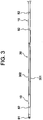
- a temperature measuring catheter 100 of the present embodiment illustrated in Fig. 1 to Fig. 8 is a catheter for measuring an internal temperature of an esophagus during an ablation operation of a left atrium.
- the temperature measuring catheter 100 includes: a catheter shaft 10 having a distal end flexible part 10A; a control handle 20 connected to the proximal end side of the catheter shaft 10; a balloon 30 connected to a distal end side of the catheter shaft 10; temperature sensors 40 (401 to 424) planarly disposed at one surface side of the balloon 30; lead wires 50 connected to respective temperature sensors 40; a first operation wire 61 for bending the distal end flexible part 10A of the catheter shaft 10 in a first direction (direction indicated by the arrow A in Fig. 1 ); a second operation wire 62 for bending the distal end flexible part 10A of the catheter shaft 10 in a second direction (direction indicated by the arrow B in Fig. 1 ); and a fluid injection tube 70.
- the reference sign 81 denotes a distal end tip
- the reference sign 82 denotes an electrode for pacing a heart.
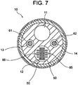
- a fluid-flowing lumen (so-called inflation lumen) 11 through which a fluid for inflating the balloon 30 flows;
- a lead insertion lumen 12 through which the lead wires 50 of the temperature sensors 40 and lead wires 85 of the electrodes 82 are inserted;
- a wire insertion lumen 13 through which the first operation wire 61 is inserted;
- a wire insertion lumen 14 through which the second operation wire 62 is inserted.
- the fluid that flows through the fluid-flowing lumen 11 is supplied from the fluid injection tube 70 to the fluid-flowing lumen 11 via an inner portion of the control handle 20 and flows from a side hole 16 opening at an outer circumferential surface of a distal end part (the distal end flexible part 10A) of the catheter shaft 10 into an inner portion (later-described first chamber 31) of the balloon 30.
- physiological saline can be exemplified.
- the outer diameter of the catheter shaft 10 is normally 1.0 to 4.0 mm.
- the length of the catheter shaft 10 is normally 300 to 1500 mm.
- thermoplastic resins such as polyamide, polyether polyamide, polyurethane, polyether block amide (PEBAX) (registered trademark), nylon, and the like, can be listed, and, among these resins, the PEBAX is preferable.
- the control handle 20 is connected to the proximal end side of the catheter shaft 10.
- a connector including a plurality of terminals is disposed in the inner portion of the control handle 20 constituting the temperature measuring catheter 100.
- the proximal ends of the lead wires 50 of the temperature sensors 40 and the proximal ends of the lead wires 85 of the electrodes 82 are connected to the terminals of the connector.
- a grip 25 for performing an operation of bending a distal end part of the catheter shaft 10 is mounted.
- the balloon 30 is connected to the distal end side of the catheter shaft 10.
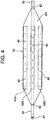
- the balloon 30 constituting the temperature measuring catheter 100 is inflated by the fluid that flows through the fluid-flowing lumen 11 of the catheter shaft 10 and has a flat shape even during inflation.
- the balloon 30 is constituted by a first sheet 301 forming one surface thereof and a second sheet 302 forming another surface thereof, the first sheet 301 and the second sheet 302 being partially fused with each other.
- the first sheet 301 is a flat sheet
- the second sheet 302 has protruding portions that are not fused with the first sheet 301.
- the first sheet 301 and the protruding portions of the second sheet 302 form fluid housing spaces during inflation.
- the first chamber 31 extending in an axial direction of the catheter shaft 10; a second chamber 32 extending parallel to the first chamber 31 on one side of the first chamber 31 with a space therebetween; a third chamber 33 extending parallel to the first chamber 31 on the other side of the first chamber 31 with a space therebetween; communication passages 34 (342) that cause the first chamber 31 and the second chamber 32 to communicate with each other; and communication passages 34 (343) that cause the first chamber 31 and the third chamber 33 to communicate with each other.
- the communication passages 34 (communication passages 342 and communication passages 343) extending from the first chamber 31 on two sides thereof are formed at an equal interval in the axial direction of the catheter shaft 10.
- the length (L30 indicated in Fig. 2 ) of the balloon 30, 30 to 100 mm is preferable, and one suitable example thereof is 60 mm.
- the width (W30 indicated in Fig. 5B ) of the balloon 30 is determined in consideration of the width of an esophagus having a shape of a flat elliptical tube (inner diameter (major diameter) of the elliptical tube).
- the thickness (H30 indicated in Fig. 5B ) of the balloon 30 during inflation is determined in consideration of the inner diameter (minor diameter) of the elliptical tube.
- resins similar to the constituent material of the catheter shaft 10 are usable.
- these resins polyurethane is preferable.
- the balloon 30 is flat even during inflation.
- a ratio of the thickness thereof to the width thereof (H30/W30) is preferably 0.1 to 0.17, and one suitable example thereof is 0.1 (2 mm/ 20 mm).
- distal end part (distal end flexible part 10A) of the catheter shaft 10 is inserted through the first chamber 31 and extends from the distal end of the first chamber 31 (balloon 30) in a state in which liquid tightness of the first chamber 31 is ensured.
- the fluid that flows into the first chamber 31 from the side hole 16 opening at the outer circumferential surface of the distal end part of the catheter shaft 10 flows through the communication passages 34 (342 and 343) and flows into the second chamber 32 and the third chamber 33, all of the housing spaces (first chamber 31, second chamber 32, third chamber 33, and communication passages 34) are filled with the fluid, and the balloon 30 is thereby inflated.
- the fluid housing spaces (first chamber 31, second chamber 32, third chamber 33, and communication passages 34) are formed in a grid shape, and fused parts between the first sheet 301 and the second sheet 302 are planarly arranged. Therefore, the balloon 30 is excellent in particular in flatness during inflation.
- the balloon 30 thus excellent in flatness, it is possible to reliably cause the flat shape of the balloon 30 to coincide with the flat elliptical tube shape of an esophagus during inflation and after contraction of the balloon 30.
- the communication passages 34 (communication passages 342 and communication passages 343) that extend from the first chamber 31 on two sides thereof being formed in the axial direction of the catheter shaft 10 at an equal interval, the communication passages 34 that are visually recognized on an X-ray image are enabled to be used as scales indicating length.
- the temperature sensors 40 (401 to 424) are planarly disposed on the one surface side of the balloon 30.
- the temperature sensors 40 (401 to 424) constituting the temperature measuring catheter 100 are constituted by, for example, measuring junctions of a thermocouple and embedded in the first sheet 301 forming one surface of the balloon 30 (the temperature sensors 40 embedded in the first sheet 301 are indicated by solid lines in Fig. 4 and Fig. 8 : in addition, illustrations of the temperature sensors 40 that appear at the cross section of the first sheet 301 are omitted in Fig. 5A to Fig. 5C .).
- the temperature sensors 40 (401 to 424) on the one surface side of the balloon 30.
- the temperature sensors 40 (401 to 408) disposed in the length direction of the balloon 30 (axial direction of the catheter shaft 10) at an equal interval constitute a first temperature-sensor group 41G
- the temperature sensors 40 (409 to 416) disposed in the aforementioned direction at an equal interval constitute a second temperature-sensor group 42G
- the temperature sensors 40 (417 to 424) disposed in the aforementioned direction at an equal interval constitute a third temperature-sensor group 43G.
- the first temperature-sensor group 41G constituted by the temperature sensors 401 to 408, the second temperature-sensor group 42G constituted by the temperature sensors 409 to 416, and the third temperature-sensor group 43G constituted by the temperature sensors 417 to 424 are arranged in the width direction of the balloon 30 at an equal interval.
- a clearance (d2 indicated in Fig. 8 ) between the temperature-sensor groups adjacent to each other in the width direction of the balloon 30, 3 to 13 mm is preferable, and one suitable example thereof is 7.5 mm.
- each of the temperature sensors 40 (401 to 408) that constitute the first temperature-sensor group 41G in the length direction of the balloon 30 and the position of each of the temperature sensors 40 (417 to 424) that constitute the third temperature-sensor group 43G in the length direction of the balloon 30 coincide with each other.
- each of the temperature sensors 40 (409 to 416) that constitute the second temperature-sensor group 42G in the length direction of the balloon 30 is shifted by (d1/2) toward the proximal end side from the position of each of the temperature sensors that constitute the first temperature-sensor group 41G or the third temperature-sensor group 43G in the length direction of the balloon 30.
- the temperature sensors 40 By disposing the temperature sensors 40 as illustrated in Fig. 8 , it is possible to measure a temperature distribution in the length direction of an esophagus with the temperature sensors 40 belonging to a respective one of the first temperature-sensor group 41G, the second temperature-sensor group 42G, and the third temperature-sensor group 43G.
- the temperature sensors 40 one example is the temperature sensor 405, the temperature sensor 412 and/or the temperature sensor 413, and the temperature sensor 421) belonging to the temperature-sensor groups that differ from each other and whose positions in the length direction of the balloon 30 are identical or close to each other.
- each of the temperature sensors 40 that constitute the second temperature-sensor group 42G in the length direction of the balloon 30 being shifted by (d1/2) toward the proximal end side from the position of each of the temperature sensors that constitute the first temperature-sensor group 41G or the third temperature-sensor group 43G in the length direction of the balloon 30, it is possible to more precisely measure a temperature distribution in the length direction of the esophagus.
- the lead wires 50 are connected to each of the temperature sensors 40 (401 to 424).
- the lead wires 50 are constituted by, for example, metal wires of different types constituting a thermocouple that uses each of the temperature sensors 40 (401 to 424) as a measuring junction.
- lead wires 50 extend in the proximal end direction in a state of being embedded in the first sheet 301 constituting the balloon 30 and enters the lead insertion lumen 12 in the vicinity of the proximal end of the first sheet 301 from a non-illustrated side hole formed at the outer circumferential surface of the catheter shaft 10.
- the lead wires 50 embedded in the first sheet 301 are indicated by solid lines.
- Fig. 4 and Fig. 5A to Fig. 5C an illustration of the lead wires 50 is omitted.
- the lead wires 50 that have entered the lead insertion lumen 12 extend, together with the lead wires 85 of the electrodes 82 for pacing, in the lead insertion lumen 12 and the inner portion of the control handle 20 and are connected to the connector.
- the distal end thereof is deflectable by pulling the first operation wire 61 and the second operation wire 62.
- Respective distal ends of the first operation wire 61 and the second operation wire 62 are fixed to the distal end part (slightly shifted toward the proximal end side from the position of the proximal end of the balloon 30) of the catheter shaft 10.
- the distal end part (distal end flexible part 10A) of the catheter shaft 10 is bendable in the first direction (direction indicated by the arrow A of Fig. 1 ) by rotating the grip 25 of the control handle 20 in a direction indicated by the arrow A1 of Fig. 1 and thereby pulling the first operation wire 61.
- the distal end part of the catheter shaft 10 is bendable in the second direction (direction indicated by the arrow B of Fig. 1 ) by rotating the grip 25 of the control handle 20 in a direction indicated by the arrow B1 of Fig. 1 and thereby pulling the second operation wire 62.
- an internal temperature of an esophagus can be measured as described below with the temperature measuring catheter 100 of the present embodiment.
- the temperature measuring catheter 100 is inserted into an inner portion of an esophagus of a subject to be operated by a nasally approach, and the balloon 30 mounted at the distal end side of the catheter shaft 10 is left at a region whose temperature should be monitored.
- the balloon 30 during the insertion is in a state of being wound (wrapped) around the distal end part of the catheter shaft 10.
- a fluid (physiological saline) is supplied from the fluid injection tube 70 into the fluid-flowing lumen 11 of the catheter shaft 10.
- the fluid supplied into the fluid-flowing lumen 11 flows into the first chamber 31 of the balloon 30 from the side hole 16 opening at the outer circumferential surface of the distal end part of the catheter shaft 10, flows through the communication passages 34 (communication passages 342 and communication passages 343), and also flows into the second chamber 32 and the third chamber 33.
- the communication passages 34 communication passages 342 and communication passages 343
- the balloon 30 after the inflation is left such that the width direction thereof coincides with the width direction of the esophagus and that the one surface side of the balloon 30 is in contact with or face the inner wall of the esophagus on the left atrium side.
- the temperature of the inner portion of the esophagus is measured with the temperature sensors 40 (401 to 424) disposed on the one surface side of the balloon 30 concurrently, and a temperature distribution is planarly grasped.
- the temperature measuring catheter 100 of the present embodiment it is possible, during an ablation operation of a left atrium, to planarly grasp a temperature distribution in an inner portion of an esophagus having a flat elliptical tube shape by measuring a temperature with the temperature sensors 40 (401 to 424) planarly disposed at the one surface side of the balloon 30, and it is possible to reliably measure the temperature of a region (region whose temperature should be monitored) whose temperature is raised by ablation with the any one of or two or more of the temperature sensors 40.
- the balloon 30 that constitutes the temperature measuring catheter 100 being flat even during inflation, it is possible during an ablation operation of a left atrium to prevent an inner wall of an esophagus from being pressed in a direction in which the left atrium is positioned by one surface of the inflated balloon 30.
- flatness of the balloon 30 during inflation is particularly excellent because the fluid housing spaces (first chamber 31, second chamber 32, third chamber 33, and communication passages 34) of the balloon 30 constituting the temperature measuring catheter 100 are formed in a grid shape, and the fused parts between the first sheet 301 and the second sheet 302 are planarly arranged.
- communication passages 34 (communication passages 342 and communication passages 343) extending from the first chamber 31 on two sides thereof being formed in the axial direction of the catheter shaft 10 at an equal interval, it is possible to use the communication passages 34 visually recognized on an X-ray image as scales indicating length.
- no ring-shaped electrode (electrode for temperature measurement) is interposed between a region whose temperature should be measured and the temperature sensors 40 (401 to 424) disposed at the one surface side of the balloon 30 in the state of being embedded in the first sheet 301; it is thus possible to quickly measure a temperature change of an inner portion of an esophagus, compared with an existing temperature measuring catheter that includes such a ring-shaped electrode.
- Fig. 9 indicates a test result of responsiveness to a temperature change in the temperature measuring catheter 100 of the present embodiment together with a test result of responsiveness to a temperature change in an existing temperature measuring catheter that includes a ring-shaped electrode.
- Fig. 9 is a graph showing results of tests in which mounting portions of the temperature sensors that had been immersed in water having a temperature of 26°C were immersed in water having a temperature of 37°C, responsiveness during a temperature rise was measured, the mounting portions of the temperature sensors were immersed in water having a temperature of 26°C, and responsiveness during a temperature fall was measured again.
- the temperature measuring catheter 100 of the present embodiment is superior to the temperature measuring catheter that includes the ring-shaped electrode in terms of responsiveness (rising and falling) to a temperature change during both of a temperature rise and a temperature fall.
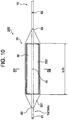
- Fig. 10 and Fig. 11 each illustrate a distal end portion of a temperature measuring catheter according to a second embodiment
- Fig. 12 illustrates a sectional view along XII-XII of Fig. 10
- Fig. 10 to Fig. 12 for constituent components identical to those of the temperature measuring catheter 100 according to the first embodiment, identical reference sings are used.
- a temperature measuring catheter 200 of the present embodiment the configuration of a balloon 35 connected to the distal end side of the catheter shaft 10 differs from that of the balloon 30 in the first embodiment.
- the balloon 35 constituting the temperature measuring catheter 200 is inflated by a fluid that flows through the fluid-flowing lumen of the catheter shaft 10 and has a flat shape even during inflation.
- the balloon 35 is constituted by a first sheet 351 forming one surface thereof and a second sheet 352 forming another surface thereof, the first sheet 351 and the second sheet 352 being partially fused with each other.
- Non-fused parts non-fused parts partitioned by the fused parts form fluid housing spaces during inflation.
- the first sheet 351 is a flat sheet
- the second sheet 352 has a protruding portion that is not fused with the first sheet 351.
- the first sheet 351 and the protruding portion of the second sheet 352 form a fluid housing space 36 during inflation.
- the protruding portion of the second sheet 352 forms flat another surface of the balloon 35.
- the length (L35 indicated in Fig. 10 ) of the balloon 35 30 to 100 mm is preferable, and one suitable example thereof is 60 mm.
- the width (W35 indicated in Fig. 12 ) of the balloon 35 is determined in consideration of the width of an esophagus having a shape of a flat elliptical tube (inner diameter (major diameter) of the elliptical tube).
- the thickness (H35 indicated in Fig. 12 ) of the balloon 30 during inflation is determined in consideration of the inner diameter (minor diameter) of the elliptical tube.
- each of the thicknesses of the first sheet 351 and the second sheet 352 constituting the balloon 35 50 to 120 ⁇ m is preferable, and one suitable example thereof is 80 ⁇ m.
- resins similar to the constituent material of the catheter shaft 10 are usable.
- these resins polyurethane is preferable.
- the balloon 35 is flat even during inflation.
- a ratio of the thickness to the width thereof (H35/W35), 0.1 to 0.17 is preferable, and one suitable example thereof is 0.1 (2 mm / 20 mm) .
- distal end part (distal end flexible part 10A) of the catheter shaft 10 is inserted through an inner portion (the fluid housing space 36) of the balloon 35 and extends from the distal end of the fluid housing space 36 in a state in which liquid tightness of the housing space 36 is ensured.
- the fluid flows into the fluid housing space 36 from the side hole 16 opening at the outer circumferential surface of the distal end part of the catheter shaft 10, and the balloon 35 is thereby inflated.
- the balloon 35 that is flat even during inflation, it is possible to cause the flat shape of the balloon 35 to coincide with the flat elliptical tube shape of the esophagus during inflation and after contraction of the balloon 35.
- a total of 24 of the temperature sensors 40 are planarly disposed on the one surface side of the balloon 35.
- the temperature sensors 40 are embedded in the first sheet 351 forming the one surface of the balloon 35.
- the temperature sensors 40 it is possible to dispose the temperature sensors 40 on the one surface side of the balloon 35. In addition, it is possible to measure a highly precise temperature distribution because the first sheet 351 in which the temperature sensors 40 are embedded is a flat sheet.
- the temperature sensors 40 embedded in the first sheet 351 are indicated by solid lines in Fig. 11 . Illustrations of the temperature sensors 40 that appear at the cross section of the first sheet 351 are omitted in Fig. 12 . In addition, illustrations of the lead wires are omitted in Fig. 11 and Fig. 12 .
- the temperature measuring catheter 200 of the present embodiment it is possible during an ablation operation of a left atrium to planarly grasp a temperature distribution in an inner portion of an esophagus having a flat elliptical tube by measuring a temperature with the temperature sensors 40 planarly disposed on the one surface side of the balloon 35, and it is possible to reliably measure the temperature of a region (region whose temperature should be monitored) whose temperature is raised by ablation with any one of or two or more of the temperature sensors 40.
- the balloon 35 that constitutes the temperature measuring catheter 200 being flat even during inflation, it is possible during an ablation operation of a left atrium to prevent an inner wall of an esophagus from being pressed in a direction in which the left atrium is positioned by one surface of the inflated balloon 35.
- no ring-shaped electrode (electrode for temperature measurement) is interposed between a region whose temperature should be measured and the temperature sensors 40 disposed on the one surface side of the balloon 35 in the state of being embedded in the first sheet 351; it is thus possible to quickly measure a temperature change of an inner portion of an esophagus, compared with an existing temperature measuring catheter that includes such a ring-shaped electrode.
- the distal end part of the catheter shaft inserted into the first chamber of the balloon may be in a state of being housed inside the first chamber without extending from the distal end of the first chamber.
- the distal end part of the catheter shaft inserted into the inner portion (fluid housing space) of the balloon may be in a state of being housed in the inner portion of the balloon without extending from the distal end of the fluid housing space.
- the communication passages that cause the first chamber and the second chamber to communicate with each other and the communication passages that cause the first chamber and the third chamber to communicate with each other may be each one communication passage.
- the position of the temperature sensors constituting the first temperature-sensor group in the length direction of the balloon, the position of the temperature sensors constituting the second temperature-sensor group in the length direction of the balloon, and the position of the temperature sensors constituting the third temperature-sensor group in the length direction of the balloon may be coincide with each other.
Landscapes
- Health & Medical Sciences (AREA)
- Life Sciences & Earth Sciences (AREA)
- Engineering & Computer Science (AREA)
- Surgery (AREA)
- Heart & Thoracic Surgery (AREA)
- General Health & Medical Sciences (AREA)
- Biomedical Technology (AREA)
- Animal Behavior & Ethology (AREA)
- Public Health (AREA)
- Veterinary Medicine (AREA)
- Medical Informatics (AREA)
- Molecular Biology (AREA)
- Pathology (AREA)
- Biophysics (AREA)
- Physics & Mathematics (AREA)
- Nuclear Medicine, Radiotherapy & Molecular Imaging (AREA)
- Pulmonology (AREA)
- Anesthesiology (AREA)
- Hematology (AREA)
- Cardiology (AREA)
- Plasma & Fusion (AREA)
- Child & Adolescent Psychology (AREA)
- Otolaryngology (AREA)
- Oral & Maxillofacial Surgery (AREA)
- Media Introduction/Drainage Providing Device (AREA)
- Measuring And Recording Apparatus For Diagnosis (AREA)
- Surgical Instruments (AREA)
Applications Claiming Priority (2)
| Application Number | Priority Date | Filing Date | Title |
|---|---|---|---|
| JP2017170895A JP6755630B2 (ja) | 2017-09-06 | 2017-09-06 | カテーテル |
| PCT/JP2018/028593 WO2019049558A1 (ja) | 2017-09-06 | 2018-07-31 | カテーテル |
Publications (2)
| Publication Number | Publication Date |
|---|---|
| EP3679976A1 true EP3679976A1 (de) | 2020-07-15 |
| EP3679976A4 EP3679976A4 (de) | 2021-06-02 |
Family
ID=65633897
Family Applications (1)
| Application Number | Title | Priority Date | Filing Date |
|---|---|---|---|
| EP18854968.7A Withdrawn EP3679976A4 (de) | 2017-09-06 | 2018-07-31 | Katheter |
Country Status (5)
| Country | Link |
|---|---|
| EP (1) | EP3679976A4 (de) |
| JP (1) | JP6755630B2 (de) |
| KR (1) | KR102282198B1 (de) |
| CN (1) | CN110545878A (de) |
| WO (1) | WO2019049558A1 (de) |
Cited By (1)
| Publication number | Priority date | Publication date | Assignee | Title |
|---|---|---|---|---|
| EP4316573A4 (de) * | 2021-03-31 | 2025-03-26 | Toray Industries, Inc. | In-vivo-temperatursteuerungssystem |
Families Citing this family (7)
| Publication number | Priority date | Publication date | Assignee | Title |
|---|---|---|---|---|
| WO2021149215A1 (ja) * | 2020-01-23 | 2021-07-29 | 日本ライフライン株式会社 | カテーテル |
| DE112020006899T5 (de) * | 2020-03-17 | 2022-12-22 | Japan Lifeline Co., Ltd | Katheterinstrument und Katheter |
| CN114746010A (zh) * | 2020-03-17 | 2022-07-12 | 日本来富恩株式会社 | 导管用器具以及导管 |
| CN111529900A (zh) * | 2020-05-14 | 2020-08-14 | 甘肃省第二人民医院 | 一种可视可调转向气囊导尿管 |
| WO2022176013A1 (ja) * | 2021-02-16 | 2022-08-25 | 日本ライフライン株式会社 | カテーテル |
| CN113229786B (zh) * | 2021-05-17 | 2023-03-24 | 河北地质大学 | 一种术中经内镜自膨胀式硅胶心房食道瘘测温装置 |
| CN113952596A (zh) * | 2021-10-28 | 2022-01-21 | 武汉威润八方医疗科技有限公司 | 一种智能化无线导尿管 |
Family Cites Families (15)
| Publication number | Priority date | Publication date | Assignee | Title |
|---|---|---|---|---|
| DE19739086C1 (de) * | 1997-09-06 | 1999-07-15 | Voelker Wolfram Priv Doz Dr Me | Ballonkatheter |
| JP2001061968A (ja) * | 1999-08-30 | 2001-03-13 | Hiroshi Terai | 動脈瘤治療具 |
| MX2009003918A (es) | 2006-10-10 | 2009-05-08 | Biosense Webster Inc | Cateter de mapeo esofagico. |
| US20080312644A1 (en) * | 2007-06-14 | 2008-12-18 | Boston Scientific Scimed, Inc. | Cryogenic balloon ablation instruments and systems |
| DK2268200T3 (en) * | 2008-03-18 | 2019-01-07 | Circa Scient Llc | TEMPERATURE MEASURING EQUIPMENT WITH LARGE SURFACE AREA |
| US20090264820A1 (en) * | 2008-04-16 | 2009-10-22 | Abiomed, Inc. | Method and apparatus for implanting an endoluminal prosthesis such as a prosthetic valve |
| JP2010004915A (ja) * | 2008-06-24 | 2010-01-14 | Toray Ind Inc | 嚥下障害治療用バルーンカテーテル |
| US9937329B2 (en) * | 2009-10-06 | 2018-04-10 | Niazi Licensing Corporation | Intra-esophageal balloon system |
| US10070793B2 (en) * | 2010-11-27 | 2018-09-11 | Securus Medical Group, Inc. | Ablation and temperature measurement devices |
| IL296643B2 (en) * | 2012-02-27 | 2025-03-01 | Fractyl Health Inc | Hot ablation systems, devices and methods for tissue treatment |
| US10568686B2 (en) * | 2013-11-21 | 2020-02-25 | Biosense Webster (Israel) Ltd. | Multi-electrode balloon catheter with circumferential and point electrodes |
| JP6116505B2 (ja) * | 2014-03-13 | 2017-04-19 | 日本ライフライン株式会社 | 温度センサ付電極カテーテル |
| HK1245067A1 (zh) * | 2015-04-06 | 2018-08-24 | C‧R‧巴德公司 | 具有外部网的可膨胀灌注球囊以及相关方法 |
| US9668720B2 (en) * | 2015-10-19 | 2017-06-06 | DNP Biomed, LLC | Systems, devices, components and methods for displacing and repositioning the esophagus away from the heart during atrial ablation surgical procedures |
| CN106725838B (zh) * | 2016-02-11 | 2024-03-29 | 上海魅丽纬叶医疗科技有限公司 | 兼具球囊扩张和射频消融功能的导管及其消融方法 |
-
2017
- 2017-09-06 JP JP2017170895A patent/JP6755630B2/ja active Active
-
2018
- 2018-07-31 CN CN201880027150.8A patent/CN110545878A/zh active Pending
- 2018-07-31 KR KR1020207004640A patent/KR102282198B1/ko not_active Expired - Fee Related
- 2018-07-31 EP EP18854968.7A patent/EP3679976A4/de not_active Withdrawn
- 2018-07-31 WO PCT/JP2018/028593 patent/WO2019049558A1/ja not_active Ceased
Cited By (1)
| Publication number | Priority date | Publication date | Assignee | Title |
|---|---|---|---|---|
| EP4316573A4 (de) * | 2021-03-31 | 2025-03-26 | Toray Industries, Inc. | In-vivo-temperatursteuerungssystem |
Also Published As
| Publication number | Publication date |
|---|---|
| JP6755630B2 (ja) | 2020-09-16 |
| KR20200031139A (ko) | 2020-03-23 |
| CN110545878A (zh) | 2019-12-06 |
| KR102282198B1 (ko) | 2021-07-27 |
| WO2019049558A1 (ja) | 2019-03-14 |
| EP3679976A4 (de) | 2021-06-02 |
| JP2019042351A (ja) | 2019-03-22 |
Similar Documents
| Publication | Publication Date | Title |
|---|---|---|
| EP3679976A1 (de) | Katheter | |
| EP3275389B1 (de) | Ablationskatheter vom ballontyp und ablationskathetervorrichtung | |
| US20240122642A1 (en) | Ablation catheter with a flexible printed circuit board | |
| DK2415495T3 (en) | Ablation catheter with balloon | |
| JP6071340B2 (ja) | 組織との直接的な接触に適合されたカテーテル | |
| JP6563251B2 (ja) | 複数の熱電対を有するカテーテル電極 | |
| JP7367118B2 (ja) | カテーテル用の潅注システム | |
| JP7051341B2 (ja) | 歪みゲージを備えた切除カテーテル | |
| JP2016093502A (ja) | センサアレイを備えた灌注アブレーションカテーテル | |
| JP6116505B2 (ja) | 温度センサ付電極カテーテル | |
| CN109199579B (zh) | 具有改善的消融尖端电极流体分布的灌注导管 | |
| WO2020178888A1 (ja) | カテーテル | |
| WO2021149215A1 (ja) | カテーテル | |
| WO2022176013A1 (ja) | カテーテル |
Legal Events
| Date | Code | Title | Description |
|---|---|---|---|
| STAA | Information on the status of an ep patent application or granted ep patent |
Free format text: STATUS: THE INTERNATIONAL PUBLICATION HAS BEEN MADE |
|
| PUAI | Public reference made under article 153(3) epc to a published international application that has entered the european phase |
Free format text: ORIGINAL CODE: 0009012 |
|
| STAA | Information on the status of an ep patent application or granted ep patent |
Free format text: STATUS: REQUEST FOR EXAMINATION WAS MADE |
|
| 17P | Request for examination filed |
Effective date: 20200327 |
|
| AK | Designated contracting states |
Kind code of ref document: A1 Designated state(s): AL AT BE BG CH CY CZ DE DK EE ES FI FR GB GR HR HU IE IS IT LI LT LU LV MC MK MT NL NO PL PT RO RS SE SI SK SM TR |
|
| AX | Request for extension of the european patent |
Extension state: BA ME |
|
| DAV | Request for validation of the european patent (deleted) | ||
| DAX | Request for extension of the european patent (deleted) | ||
| A4 | Supplementary search report drawn up and despatched |
Effective date: 20210430 |
|
| RIC1 | Information provided on ipc code assigned before grant |
Ipc: A61M 25/10 20130101AFI20210423BHEP Ipc: A61B 5/01 20060101ALI20210423BHEP Ipc: A61B 5/00 20060101ALI20210423BHEP |
|
| STAA | Information on the status of an ep patent application or granted ep patent |
Free format text: STATUS: THE APPLICATION IS DEEMED TO BE WITHDRAWN |
|
| 18D | Application deemed to be withdrawn |
Effective date: 20211130 |