EP3676524B1 - Dispositif de sécurité pour le passage de tuyaux sur des bateaux - Google Patents
Dispositif de sécurité pour le passage de tuyaux sur des bateaux Download PDFInfo
- Publication number
- EP3676524B1 EP3676524B1 EP18796493.7A EP18796493A EP3676524B1 EP 3676524 B1 EP3676524 B1 EP 3676524B1 EP 18796493 A EP18796493 A EP 18796493A EP 3676524 B1 EP3676524 B1 EP 3676524B1
- Authority
- EP
- European Patent Office
- Prior art keywords
- semi
- flanges
- flange
- safety device
- profiles
- Prior art date
- Legal status (The legal status is an assumption and is not a legal conclusion. Google has not performed a legal analysis and makes no representation as to the accuracy of the status listed.)
- Active
Links
- 230000008878 coupling Effects 0.000 claims description 21
- 238000010168 coupling process Methods 0.000 claims description 21
- 238000005859 coupling reaction Methods 0.000 claims description 21
- 230000006835 compression Effects 0.000 claims description 5
- 238000007906 compression Methods 0.000 claims description 5
- 239000000463 material Substances 0.000 claims description 5
- OKTJSMMVPCPJKN-UHFFFAOYSA-N Carbon Chemical compound [C] OKTJSMMVPCPJKN-UHFFFAOYSA-N 0.000 claims description 4
- 230000009970 fire resistant effect Effects 0.000 claims description 4
- 229910002804 graphite Inorganic materials 0.000 claims description 4
- 239000010439 graphite Substances 0.000 claims description 4
- 238000007789 sealing Methods 0.000 claims description 4
- 238000009412 basement excavation Methods 0.000 claims description 2
- 230000003068 static effect Effects 0.000 claims description 2
- 239000003795 chemical substances by application Substances 0.000 claims 2
- 238000009434 installation Methods 0.000 description 7
- 238000012856 packing Methods 0.000 description 7
- 230000008901 benefit Effects 0.000 description 4
- 238000010276 construction Methods 0.000 description 4
- 238000012423 maintenance Methods 0.000 description 4
- 238000004519 manufacturing process Methods 0.000 description 3
- XLYOFNOQVPJJNP-UHFFFAOYSA-N water Substances O XLYOFNOQVPJJNP-UHFFFAOYSA-N 0.000 description 3
- XEEYBQQBJWHFJM-UHFFFAOYSA-N Iron Chemical compound [Fe] XEEYBQQBJWHFJM-UHFFFAOYSA-N 0.000 description 2
- 239000007789 gas Substances 0.000 description 2
- 239000007788 liquid Substances 0.000 description 2
- 238000000034 method Methods 0.000 description 2
- 230000008569 process Effects 0.000 description 2
- 230000009467 reduction Effects 0.000 description 2
- 238000007514 turning Methods 0.000 description 2
- RNFJDJUURJAICM-UHFFFAOYSA-N 2,2,4,4,6,6-hexaphenoxy-1,3,5-triaza-2$l^{5},4$l^{5},6$l^{5}-triphosphacyclohexa-1,3,5-triene Chemical compound N=1P(OC=2C=CC=CC=2)(OC=2C=CC=CC=2)=NP(OC=2C=CC=CC=2)(OC=2C=CC=CC=2)=NP=1(OC=1C=CC=CC=1)OC1=CC=CC=C1 RNFJDJUURJAICM-UHFFFAOYSA-N 0.000 description 1
- 229910000975 Carbon steel Inorganic materials 0.000 description 1
- 229910000640 Fe alloy Inorganic materials 0.000 description 1
- RTAQQCXQSZGOHL-UHFFFAOYSA-N Titanium Chemical compound [Ti] RTAQQCXQSZGOHL-UHFFFAOYSA-N 0.000 description 1
- 229910052782 aluminium Inorganic materials 0.000 description 1
- XAGFODPZIPBFFR-UHFFFAOYSA-N aluminium Chemical compound [Al] XAGFODPZIPBFFR-UHFFFAOYSA-N 0.000 description 1
- 238000004873 anchoring Methods 0.000 description 1
- 238000013475 authorization Methods 0.000 description 1
- 230000004888 barrier function Effects 0.000 description 1
- 239000010962 carbon steel Substances 0.000 description 1
- 238000004049 embossing Methods 0.000 description 1
- 238000005516 engineering process Methods 0.000 description 1
- 230000007613 environmental effect Effects 0.000 description 1
- 238000004079 fireproofing Methods 0.000 description 1
- 239000003063 flame retardant Substances 0.000 description 1
- 239000006260 foam Substances 0.000 description 1
- 229910052742 iron Inorganic materials 0.000 description 1
- 238000003754 machining Methods 0.000 description 1
- 229910052751 metal Inorganic materials 0.000 description 1
- 239000002184 metal Substances 0.000 description 1
- 238000003801 milling Methods 0.000 description 1
- 210000000056 organ Anatomy 0.000 description 1
- 239000013589 supplement Substances 0.000 description 1
- 238000012360 testing method Methods 0.000 description 1
- 229910052719 titanium Inorganic materials 0.000 description 1
- 239000010936 titanium Substances 0.000 description 1
- 238000004078 waterproofing Methods 0.000 description 1
- 238000003466 welding Methods 0.000 description 1
Images


Classifications
-
- B—PERFORMING OPERATIONS; TRANSPORTING
- B63—SHIPS OR OTHER WATERBORNE VESSELS; RELATED EQUIPMENT
- B63B—SHIPS OR OTHER WATERBORNE VESSELS; EQUIPMENT FOR SHIPPING
- B63B19/00—Arrangements or adaptations of ports, doors, windows, port-holes, or other openings or covers
- B63B19/12—Hatches; Hatchways
- B63B19/26—Gaskets; Draining means
-
- F—MECHANICAL ENGINEERING; LIGHTING; HEATING; WEAPONS; BLASTING
- F16—ENGINEERING ELEMENTS AND UNITS; GENERAL MEASURES FOR PRODUCING AND MAINTAINING EFFECTIVE FUNCTIONING OF MACHINES OR INSTALLATIONS; THERMAL INSULATION IN GENERAL
- F16L—PIPES; JOINTS OR FITTINGS FOR PIPES; SUPPORTS FOR PIPES, CABLES OR PROTECTIVE TUBING; MEANS FOR THERMAL INSULATION IN GENERAL
- F16L5/00—Devices for use where pipes, cables or protective tubing pass through walls or partitions
- F16L5/02—Sealing
- F16L5/04—Sealing to form a firebreak device
-
- F—MECHANICAL ENGINEERING; LIGHTING; HEATING; WEAPONS; BLASTING
- F16—ENGINEERING ELEMENTS AND UNITS; GENERAL MEASURES FOR PRODUCING AND MAINTAINING EFFECTIVE FUNCTIONING OF MACHINES OR INSTALLATIONS; THERMAL INSULATION IN GENERAL
- F16J—PISTONS; CYLINDERS; SEALINGS
- F16J15/00—Sealings
- F16J15/02—Sealings between relatively-stationary surfaces
- F16J15/021—Sealings between relatively-stationary surfaces with elastic packing
- F16J15/028—Sealings between relatively-stationary surfaces with elastic packing the packing being mechanically expanded against the sealing surface
-
- F—MECHANICAL ENGINEERING; LIGHTING; HEATING; WEAPONS; BLASTING
- F16—ENGINEERING ELEMENTS AND UNITS; GENERAL MEASURES FOR PRODUCING AND MAINTAINING EFFECTIVE FUNCTIONING OF MACHINES OR INSTALLATIONS; THERMAL INSULATION IN GENERAL
- F16L—PIPES; JOINTS OR FITTINGS FOR PIPES; SUPPORTS FOR PIPES, CABLES OR PROTECTIVE TUBING; MEANS FOR THERMAL INSULATION IN GENERAL
- F16L5/00—Devices for use where pipes, cables or protective tubing pass through walls or partitions
- F16L5/02—Sealing
- F16L5/08—Sealing by means of axial screws compressing a ring or sleeve
-
- F—MECHANICAL ENGINEERING; LIGHTING; HEATING; WEAPONS; BLASTING
- F16—ENGINEERING ELEMENTS AND UNITS; GENERAL MEASURES FOR PRODUCING AND MAINTAINING EFFECTIVE FUNCTIONING OF MACHINES OR INSTALLATIONS; THERMAL INSULATION IN GENERAL
- F16L—PIPES; JOINTS OR FITTINGS FOR PIPES; SUPPORTS FOR PIPES, CABLES OR PROTECTIVE TUBING; MEANS FOR THERMAL INSULATION IN GENERAL
- F16L5/00—Devices for use where pipes, cables or protective tubing pass through walls or partitions
- F16L5/02—Sealing
- F16L5/10—Sealing by using sealing rings or sleeves only
Definitions
- the present invention concerns in particular the field of nautical installations, with particular reference to the installation on board of boats of pipes of all sizes and kinds.
- the present invention deals with devices for routing pipes on deck and bulkheads separating the various vanes/spaces/housings of a boat.
- this invention describes a device for the passage of pipes for liquids or gases through bulkheads and decks of yachts, mega yachts and naval units in general with fireproof characteristics (corresponding at least to international standards, such as A60).
- the main criticalities of the current deck and bulkhead passages derive from several factors including: excessive overall dimensions of these passages which, where necessary, do not allow, on already launched vessels, deviations of the pipes passing through secondary areas of lounges, chambers, etc. of yachts, mega yachts and naval units in general.
- a further problem is the difficulty of lateral pipe deflection.
- a further negative aspect derives from the reduction of the intrinsic resistance characteristics of the walls through which such passages pass and/or from the reduction of the resistance/solidity of the same pipes due to the need of the current systems/devices to perform welding to fix the passages directly on the walls and/or pipes, obviously reducing the resistance characteristics of both structures and/or pipes, with consequent fatigue of the structures and/or pipes themselves, to the disadvantage of the life/wear time.
- EP 0 964 196 A1 discloses water-tight and fire resistant bulkhead passages or bridges.
- Several metal flanges are associated and connected to each other by mechanical means and, to ensure a correct and strong tight-engagement of the continuous pipes that pass through bulkheads or bridges.
- Water-tight gaskets and intumescent thermo-expanding gaskets constituting fire-resistant barriers are associated and connected to the coupled flanges.
- the so constituted, water-tight and fire-resistant bulkhead passages or bridges are suitable for onboard naval application for off-shore platforms and/or compartment-rooms in general.
- a further purpose of this invention is to describe a space-saving deck and bulkhead pipe passage device.
- a safety device according to claim 1 is provided.
- Said safety device for the passage of deck and bulkhead pipes includes at least a static sealing device comprising at least a double flange suitable for being fixed in a sleeve/passage of any diameter suitable for the passage of boat pipes, said double flange comprising at least two cylindrical-shaped flange sides, which can be coupled together, said device being advantageously characterized by the fact that said flange sides are in turn divided into at least two or more further semi-flanges each in the form of a cylindrical sector, said semi-flanges being of at least two types and including coupling areas to be coupled facing each other to form said first flange side and coupling areas to be coupled and form said second flange side said flanges being coupled facing each other to form a double flange, the device being modular and including any number of semi-flanges being assembled directly on board of a boat in boat deck and/or bulkheads sleeves/tube passages of any type, being adaptable also to pre-existing passages.
- the device in a further advantageous way such at least one gasket, included in the device and housed there as will be described below, being for example preferably made of graphite, makes the device both fireproof and watertight.
- the gasket thus defined may comprise a number of gasket sections to form an assembly, such an assembly of gasket sections or parts being properly assembled with each other and with the device.
- Such a gasket(s) or an assembly of parts/sections of gasket(s) is (are) placed between such at least a first and said at least a second flange, both following the outer circumference of the flange and the inner one, moreover said gasket is also further placed in the areas of coupling between the various semi-flanges, this will be described more clearly with reference to the figures attached below.
- the coupling of the at least two flanges compresses said gaskets both towards the outside and towards the inside of the passage itself (the passage remaining between the outer circumference of the device and the hole physically made in the deck/bulkhead).
- This compression occurs by virtue of the shape of the flanges/semi-flanges themselves, which are of at least two types: a first flange and the relative semi-flanges are made with an internal and external circumference in the form of a cylindrical crown, with edges or external profiles raised with respect to the plane of the first type semi-flange; these profiles in particular may have preferably a cuneiform section; a second flange and any relative semi-flanges, on the other hand, are made with an internal and external circumference in the form of a cylindrical crown with edges or external profiles lowered with respect to the plane of the flange or relative semi-flanges constituting the said flange, which faces the relative further semi-flange or flange suitable for coupling with it.
- these semi-flanges include at least one abutting element, for example of cuneiform shape. This abutting element develops radially from the external radius to the internal radius of the semi-flanges of the "male” type, there is a number of abutting elements of choice in each semi-flange male.
- Such male semi-flanges include external semi-crowns with radius r1, of any thickness, the profile of said external male semi-crowns is preferably abutting of preferably of cuneiform shape, the same is true for the internal semi-crowns of said first male semi-flange, of radius r2, with any thickness.
- Second type semi-flanges which will be defined as “female” in the areas of coupling with each other, include depressions which, when coupled, form areas of housing for at least one part of the gasket or packing. These zones develop substantially radially from the outer radius r1 to the inner radius r2 of the female semi-flange.
- These coupling zones suitable to house at least part of said gasket assembly, during the assembly phase will be placed in correspondence with the abutting elements of the male semi-flanges, in this way this element advantageously compresses this part of the gasket towards the sides and the bottom of the housing formed by the coupling zones of the female semi-flanges.
- said female semi-flanges Sfout include external semi-crowns with radius r1 of any thickness provided compatible with the thickness of the male semi-flanges, and identically internal semi-crowns of radius r2 having the same characteristics.
- the internal profile r2 of said female external semi-crowns includes a depression that develops along the semi-circular crown, this depression or overhang, forming a housing stricture.
- the housings Sf of the female semi-flanges including said gasket portions are coupled with the corresponding internal and external profiles Smint and Smout of the male semi-flanges; in a particularly advantageous way, the profiles Sm are suitable for compressing the relative gaskets towards the interior of the housing Sf, or rather close to the jutting or better said, of the shoulder of the female semi-flange and also towards the exterior of the housing:
- the portion of the external gasket that develops on the circular profile of radius r1 is compressed onto the sleeve/tube liner that is inserted into the wall of the deck/bulkhead in which the device is housed.
- the gasket housed in the internal housing is compressed towards the interior of the housing close to the female semi-flange on one side and close to the tube passing through on the other. While the gasket present in the radial housings of the female semi-flanges is compressed by the radial element of the male semi-flanges, compressing it against the two shoulders of the female semi-flanges and against the bottom of the housing: it should be noted that in this way, the same sealing characteristics are guaranteed in an innovative way between the sleeve/flange and the deck/flange between the male semi-flange and the female semi-flange in the areas corresponding to the circumferences, parts of the circumferences and relative housings, radii r1 and r2.
- the aforementioned sealing systems housed within the structure of the passage, ensure that in the event of fire and/or flooding, the fireproof and waterproof (watertight) characteristics are respected within 10 meters of waterline.
- thermo-expanding tape is housed in the entire perimeter of the passage which, in the event of fire, has the capacity to increase its volume up to 16 times its original size.
- the device or organ with at least a double flange is assembled in such a way as to compress both towards the outside and towards the inside of the passage itself the aforementioned gaskets housed during the assembly phase within its structure, guaranteeing, in the event of fire and/or flooding, the characteristics of the A60 fire stop (direct flames at 1000 degrees Celsius for 60 minutes) and water resistance (watertight) up to 10 meters under the waterline.
- the passages also allow a limited axial movement of the pipe relative to the deck or bulkhead concerned, so as to absorb any expansion or vibration without this affecting the fire and water resistance characteristics described above.
- the transport and maintenance of this device is also extremely simplified, the device therefore allows high practicality for subsequent disassembly and reassembly where maintenance needs should become necessary, resulting in considerable savings in time and money for the owner and/or manufacturer.
- the device which is the subject of this invention shall also ensure continuity to the deck or bulkhead which is being worked on without the need for additional space.
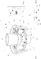
- device 1 includes at least a pair of flanges 2a, 2b, for which the device will be defined as double flange, these flanges are suitable to couple with each other, as it will be described below.
- the mechanical safety device 1 with at least double flange 2A, 2B can be divided into several sectors, or semi-flanges, suitably shaped through the process of turning and milling.
- Such flanges 2A,2B are defined as at least one male flange 2A and at least one female flange 2B and include at least any number of semi-flanges 2a', 2a", 2b',2b" etc. each of which is a male flange 2a', 2a" etc., being suitable for coupling to one or more of its female semi-flanges 2b', 2b" etc..
- These semi-flanges 2a', 2b' are made with circumference Cint, Cout internal and external in the shape of a circular crown, with edges or external and internal profiles 20aint and 20aout of radius respectively r2 and r1 (better visible in fig.2 ) that are raised with respect to the plane of the semi-flange of first type 2an (in particular to the plane that faces to couple with the semi-flange of second type 2bn), these profiles can have preferably wedge-shaped section 20a. At least one flange 2b of second type and its semi-flanges, if any, 2b',2b" etc.
- This shoulder which is hereafter also referred to independently as an overhang or depression 20b each forming a suitable enclosure to accommodate a portion of a gasket 3 or gasket assembly 3.
- This abutting element 21 develops radially from the external radius r1 to the internal radius r2 of the semi-flanges of type "male" 2'a, and there is any number of elements 21 in each semi-flange 2a',2a",2an according to the number of semi- male flanges 2an (and relative female semi-flanges 2'bn).
- the semi-flanges 2bn ( fig. 1b ) on the other hand in the coupling zones one with the other include depressions that coupled together form housing zones 31 for at least a part of gasket 3 or a gasket 3. These zones develop radially from the outer radius r1 to the inner radius r2 of the female semi-flange and have length L substantially equal to the length of element 21.
- Said housing zones 31, suitable to house at least part of said gasket assembly 3, during assembly with the male semi-flanges, will be placed in correspondence with the abutting elements 21 of the male semi-flanges 2A, in this way such element or profile 21 advantageously compresses the gaskets 3 housed therein towards the bottom and the sides of the housing 31 formed by the coupling of the lowered coupling zones of the female semi-flanges 2b'.
- the coupling zones of the female flanges 2bn form housings 31, suitable to house a gasket part 3.
- the male semi-flanges are placed with zones 21 facing said housing 31, so that these abutting elements compress the gaskets 3 in the housings 31.
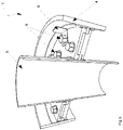
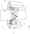
- said device 1 shall include at least bolts or means suitable for purpose 6 for fixing the semi-flanges 2'a and 2'b together and further shall include at least retainers 8 and/or hooks 8 for fixing the sleeve/tube liner 4 with at least one of the semi-flanges 2a or 2b to assembled device 1.
- This device therefore acts in a very advantageous way as a device for compressing of the gaskets 3 in all directions, i.e. compressing and thus conferring a watertight seal between device 1 and sleeve 4 and also between device 1 and the through tube, as well as in the areas of junction between the various elements or flanges and semi-flanges of device 1, making this device 1 assembled with its sleeve/tube liner and through tube, totally watertight and fireproof as certified at least up to two meters (as above).
- this device 1 can further include and accommodate in the entire perimeter/circumference r2 of the passage, or wrapped on the passing pipe, and also outside in the perimeter/circumference r1, or close to the sleeve, a special material such as a thermo-expanding tape that, in case of fire has the ability to increase its volume up to at least sixteen times its original size.
- a special material such as a thermo-expanding tape that, in case of fire has the ability to increase its volume up to at least sixteen times its original size.
- the deck and bulkhead passage device object of the present application also has the additional characteristic of being a self-supporting system.
- the passages thus constructed once fixed through the closure of the bolts on the semi-flanges are able, through the sole force of compression of the seal fixed there, to block the entire structure of the passage to the wall or deck without any further need for installation of other anchoring systems. Therefore, this device is a self-supporting device by means of the compressive force between the device and the sleeve/tube.
- welded retainers are inserted on the sleeve to prevent that, in the event of flooding, the pressure of the water exerted on the passage system, involves the movement and therefore the frustration of its specific characteristics.
- device 1 characterized by a modular system of semi-flanges surrounded by seal/gasket 3 preferably in graphite, allows a limited axial movement of the pipe in relation to the deck or bulkhead affected by the passage itself so as to absorb any expansion or vibration without this affecting the fire and waterproofing characteristics described above.
- the device 1 is advantageously sealed with said gaskets 3 or packing (term of the sector) preferably in graphite and at least gaskets 3 for example preferably in a thermo-expanding material; in case of fire these gaskets turn into a foam with high insulating power with a thickness up to 16 times the initial thickness
- gasket 3 or gasket assembly 3
- gaskets with a shape and contour suitable for each housing defined in this gasket, all having the same purpose and function for simplicity any element or part formed by the gasket/packing 3 assembly is defined as gasket 3.
- the passages generally allow the lateral deflection of the pipes and the crossing of decks and/or bulkheads of yachts, mega yachts and naval units in general for the carbon steel pipes for the transport of liquids or gases, with internal pressure equal to or different from the atmospheric pressure, with internal temperature equal to or different from the environmental temperature, by virtue of this invention are guaranteed at the same time the maintenance of the characteristics of A60 fireproof and waterproof (watertight) up to 10 meters of waterline of decks or naval bulkheads crossed.
- the passages also allow to make the structure of the deck and/or the bulkhead crossed by these types of pipes continuous eliminating any breaking points in case of accidents.
- the passage device may be designed, constructed and then subdivided into a number "n" of any of the sections, without this solution affecting the characteristics proper to the invention itself or modifying its scope of protection.
Landscapes
- Engineering & Computer Science (AREA)
- General Engineering & Computer Science (AREA)
- Mechanical Engineering (AREA)
- Chemical & Material Sciences (AREA)
- Combustion & Propulsion (AREA)
- Ocean & Marine Engineering (AREA)
- Gasket Seals (AREA)
- Building Environments (AREA)
- Rigid Pipes And Flexible Pipes (AREA)
- Flanged Joints, Insulating Joints, And Other Joints (AREA)
- Filling Or Discharging Of Gas Storage Vessels (AREA)
Claims (7)
- Un dispositif de sécurité (1) de passage de tuyaux (5) sur ponts de bateaux et cloisons de bateaux, comprenant au moins un organe d'étanchéité statique comportant au moins une double bride (2) destinée à être fixée dans un manchon/passages de tubes (4) de tout diamètre adapté au passage de tuyaux pour bateaux, ladite double bride (2) comprenant au moins deux côtés de bride de forme cylindrique (2a, 2b), qui sont couplés à un autre, dans lequel ledit dispositif de sécurité (1) comprend un joint (3) ou un ensemble de joints (3), où lesdits côtés de bride (2a, 2b) sont à leur tour divisés en au moins deux ou plusieurs demi-brides chacune (2a ', 2a" -2b' 2b") en forme de secteur cylindrique, lesdites demi-brides (2a', 2a"- 2b',2b") comportant des zones d'accouplement (34) à coupler pour former un premier côté de bride (2a) et des zones d'accouplement (30) à coupler pour former un deuxième côté de bride (2b), lesdits côtés de bride étant couplés en vis-à-vis entre eux pour former la double bride, le dispositif de sécurité étant modulaire et comprenant plusieurs demi-brides adaptées pour être assemblées directement à bord d'un bateau, sur le pont du bateau et/ou dans des manchon/passages de tubes (4) de cloisons de tout type, étant également adaptables aux passages de tubes (4) préexistants, lesdites demi-brides (2a) du premier côté de bride étant des demi-brides mâles comprenant des profils intérieurs (20aint), des profils extérieurs (20aout) et des profils radiaux (21) tous surélevés au-dessus du plan des demi-brides (2a', 2a") et desdites demi-brides (2bn) du deuxième côté de bride étant des demi-brides femelles comprenant des profils internes (20bint), des profils externes (20bout) et des profils radiaux (30) surbaissés par rapport au plan des demi-brides (2b', 2b"), lesdits profils intérieurs (20bint), profils extérieurs (20bout) et profils radiaux (30) desdites demi-brides (2b', 2b") du deuxième côté de bride formant des logements (31, 33) pour loger ledit joint (3) ou ensemble de joints (3) dudit dispositif de sécurité, dans lequel les demi-brides (2a', 2b') sont réalisées avec une circonférence (Cint, Cout) intérieure et extérieure en forme de couronne circulaire, avec des arêtes ou profils extérieurs et intérieurs (20aout, 20aint) de rayon respectif (r2,r1) relevés par rapport au plan de la demi-bride du premier côté (2a', 2a"), ces profils ayant de préférence une section en forme de bord (20a), dans lequel au moins une bride (2b) du deuxième côté et ses demi-brides (2b', 2b") sont réalisées avec une circonférence interne et externe en forme de couronne circulaire (Cint, Cout) avec bords ou profils externes et internes (20bout, 20bint) de rayon respectif (r1, r2) en relief et abaissés, avec une excavation en creux (20b) par rapport au reste du plan de bride (2b), notamment au plan qui fait face pour se coupler à la bride du premier côté (2a',2a") et/ou sa demi-bride (2a'2a") constituant ladite bride.
- Le dispositif de sécurité (1) pour le passage de tuyaux à bord de pont et de cloison de bateaux, selon la revendication 1, où lesdits profils internes (20aint), profils externes (20aout) et profils radiaux (21) sont adaptés pour écraser et comprimer lesdits joints (3) logés dans lesdits logements (31, 33), ledit dispositif de sécurité (1) résistant au feu et étant étanche jusqu'à 10 mètres.
- Le dispositif de sécurité (1) pour le passage de tuyaux à bord du pont et de la cloison des bateaux selon l'une quelconque des revendications précédentes, où les profils (20aint, 20aout) sont adaptés pour comprimer les joints relatifs (3) dans les logements (33), c'est-à-dire à proximité des épaulements (20bint et 20bout) des demi-brides (2bn) et également vers l'extérieur du logement (33) ou respectivement contre le conduit traversant (5) dans le cas du joint logé dans le logement (33/20bint) et à proximité du manchon/tube (4) dans le cas du joint logé dans le logement (33/20bout).
- Le dispositif de sécurité (1) pour le passage de tuyaux à bord de pont et de cloison de bateaux, selon l'une quelconque des revendications précédentes, où ledit profil (21) comprime les joints (3) logés dans les logements (31) vers le bas et les côtés du logement (31) formés par l'accouplement des zones d'assise abaissées (30) des demi-brides femelles (2bn).
- Le dispositif de sécurité (1) pour le passage des tuyaux à bord du pont et de la cloison des bateaux, selon l'une quelconque des revendications précédentes, où lesdits joints (3) sont en graphite ou autre matériau approprié pour rendre le dispositif de sécurité à la fois ignifuge et étanche.
- Le dispositif de sécurité (1) pour le passage de tuyaux à bord du pont et de la cloison de bateaux, selon l'une quelconque des revendications précédentes, où ledit dispositif de sécurité (1) comprend un agent thermo-expansif placé, en utilisation, enroulé autour dudit tube (5) et/ou adjacent auxdits passages/manchon (4), ledit agent thermo-expansif ayant la capacité d'augmenter son volume jusqu'à au moins seize fois son encombrement d'origine en cas d'incendie.
- Le dispositif de sécurité (1) pour le passage de tuyaux à bord du pont et de la cloison de bateaux, selon l'une quelconque des revendications précédentes, où lesdites demi-brides et brides sont fixées au moyen de goupilles et/ou de boulons (6) du dispositif de sécurité (1), ledit dispositif de sécurité (1) étant, en utilisation, un dispositif autoportant au moyen de la force de compression entre le dispositif et le manchon/tube de passage (4).
Priority Applications (1)
| Application Number | Priority Date | Filing Date | Title |
|---|---|---|---|
| HRP20230082TT HRP20230082T1 (hr) | 2017-09-26 | 2018-09-26 | Sigurnosni uređaj za prolaz cijevi na brodovima |
Applications Claiming Priority (3)
| Application Number | Priority Date | Filing Date | Title |
|---|---|---|---|
| IT102017000107809A IT201700107809A1 (it) | 2017-09-26 | 2017-09-26 | Dispositivo di sicurezza per tubazioni navali |
| IT201800007599 | 2018-07-27 | ||
| PCT/IB2018/057433 WO2019064191A1 (fr) | 2017-09-26 | 2018-09-26 | Dispositif de sécurité pour le passage de tuyaux sur des bateaux |
Publications (2)
| Publication Number | Publication Date |
|---|---|
| EP3676524A1 EP3676524A1 (fr) | 2020-07-08 |
| EP3676524B1 true EP3676524B1 (fr) | 2022-11-02 |
Family
ID=64083121
Family Applications (1)
| Application Number | Title | Priority Date | Filing Date |
|---|---|---|---|
| EP18796493.7A Active EP3676524B1 (fr) | 2017-09-26 | 2018-09-26 | Dispositif de sécurité pour le passage de tuyaux sur des bateaux |
Country Status (16)
| Country | Link |
|---|---|
| US (1) | US11591046B2 (fr) |
| EP (1) | EP3676524B1 (fr) |
| JP (1) | JP7273804B2 (fr) |
| KR (1) | KR102658147B1 (fr) |
| CN (1) | CN111108318B (fr) |
| AU (1) | AU2018341142B2 (fr) |
| CA (1) | CA3075245A1 (fr) |
| DK (1) | DK3676524T3 (fr) |
| ES (1) | ES2937821T3 (fr) |
| FI (1) | FI3676524T3 (fr) |
| HR (1) | HRP20230082T1 (fr) |
| PL (1) | PL3676524T3 (fr) |
| SA (1) | SA520411619B1 (fr) |
| SG (1) | SG11202002465XA (fr) |
| WO (1) | WO2019064191A1 (fr) |
| ZA (1) | ZA202002149B (fr) |
Families Citing this family (5)
| Publication number | Priority date | Publication date | Assignee | Title |
|---|---|---|---|---|
| US10865572B2 (en) * | 2018-05-31 | 2020-12-15 | Dima Building Innovators LLC | Hole protector device for mechanical, plumbing, and electrical (MPE) systems |
| IT201900024598A1 (it) * | 2019-12-18 | 2021-06-18 | Luciano Lombardi | Dispositivo di sicurezza nautica per passaggi di linee d'asse |
| IT202000004735A1 (it) * | 2020-03-05 | 2021-09-05 | Luciano Lombardi | Dispostivo compatto di sicurezza nautica per passaggi ponte paratia |
| IT202000010432A1 (it) * | 2020-05-08 | 2021-11-08 | Luciano Lombardi | Dispositivo per la gestione in sicurezza di scarichi navali |
| IT202000013654A1 (it) * | 2020-06-08 | 2021-12-08 | Luciano Lombardi | Dispositivo di sicurezza nautica per passaggi multitubo ponte paratia |
Family Cites Families (33)
| Publication number | Priority date | Publication date | Assignee | Title |
|---|---|---|---|---|
| US1851940A (en) * | 1929-11-13 | 1932-03-29 | Orr H Williams | Closure for conduits and the like |
| US3647230A (en) * | 1969-07-24 | 1972-03-07 | William L Smedley | Well pipe seal |
| US3649034A (en) * | 1970-09-15 | 1972-03-14 | Thunderline Corp | Modular interwall seal unit |
| US3655907A (en) * | 1970-10-16 | 1972-04-11 | O Z Electrical Mfg Co Inc | Conduit cable seal |
| JPS53129719U (fr) * | 1977-03-23 | 1978-10-14 | ||
| US4406484A (en) * | 1981-03-05 | 1983-09-27 | Ramer James L | Manhole fluid line attachment apparatus |
| JPS592376Y2 (ja) * | 1982-08-18 | 1984-01-23 | 株式会社ハツコ− | 地下構造物の管体貫通部の防水構造 |
| JPS6054873U (ja) * | 1983-09-22 | 1985-04-17 | 宇部興産株式会社 | 配管ゲ−ト |
| US4699405A (en) * | 1986-04-15 | 1987-10-13 | International Clamp Company | Coupling for coupling tubular members |
| US4717160A (en) * | 1986-04-21 | 1988-01-05 | Microdot Inc. | High pressure rotary shaft seal |
| DE3828693C1 (fr) * | 1988-08-24 | 1989-10-26 | Plastoform Gmbh & Co Kg, 4973 Vlotho, De | |
| US4936064A (en) * | 1989-02-16 | 1990-06-26 | Backer Rod Manufacturing And Supply Company | Fireproof panel |
| DE9105956U1 (de) * | 1991-05-14 | 1991-11-28 | Trumpf Lasertechnik GmbH, 7257 Ditzingen | Verbindungsvorrichtung |
| US5458343A (en) * | 1994-08-11 | 1995-10-17 | General Electric Company | Aircraft engine firewall seal |
| EP0859926B1 (fr) * | 1995-07-28 | 2000-02-02 | Kvaerner Pulping AB | Unite de dilatation pour l'adaptation de conduites |
| US5697194A (en) * | 1996-06-18 | 1997-12-16 | Psi Telecommunications, Inc. | Modular seal assembly for a wall opening |
| DE29709983U1 (de) * | 1997-06-07 | 1998-04-09 | WEMA Werkzeug + Maschinenbau GmbH, 21447 Handorf | Abdichtende Rohr- und Kabeldurchführung |
| DE29723073U1 (de) * | 1997-06-12 | 1998-04-09 | DOYMA GmbH & Co, 28876 Oyten | Dichtungsvorrichtung zum abdichtenden Durchführen mindestens einer Leitung |
| ATE260431T1 (de) * | 1998-06-12 | 2004-03-15 | Chibro S P A | Wasserdichte, feuerbeständige durchführungsöffnungen |
| NL1012759C2 (nl) * | 1999-08-02 | 2001-02-05 | Beele Eng Bv | Afdichtsamenstel en afdichtmanchet hiervoor. |
| DE19955766C2 (de) * | 1999-11-19 | 2003-04-03 | Hilti Ag | Verfahren und Vorrichtung zum Abdichten des Spalts zwischen einer in einem Bauelement vorhandenen Durchführung und einem die Durchführung durchragenden Gegenstand |
| DE50015126D1 (de) * | 2000-06-17 | 2008-06-05 | Hauff Technik Gmbh & Co Kg | Dichtpackung zum Hindurchführen von Leitungen durch eine Wand |
| GB0110206D0 (en) | 2001-04-26 | 2001-06-20 | 3D Composites Ltd | Pipe seal |
| DE20200374U1 (de) * | 2002-01-11 | 2003-05-22 | DOYMA GmbH & Co, 28876 Oyten | Dichtungsvorrichtung |
| EP1519092A1 (fr) * | 2003-09-24 | 2005-03-30 | Tony Ekat | Méthode d'étanchéification du passage de tuyaux dans une paroi |
| ES2394649T3 (es) * | 2006-03-20 | 2013-02-04 | Beele Engineering B.V. | Sistema para sellar dinámicamente un manguito de canalización a través del cual se extiende un tubo o cable |
| SE530482C2 (sv) * | 2007-05-16 | 2008-06-17 | Roxtec Ab | Tätning med brandskydd |
| JP5543744B2 (ja) * | 2009-09-01 | 2014-07-09 | 積水化学工業株式会社 | 防火区画貫通部構造 |
| JP6016653B2 (ja) * | 2013-01-31 | 2016-10-26 | 三菱重工業株式会社 | シール構造 |
| CN204176159U (zh) * | 2014-10-29 | 2015-02-25 | 烟台中集来福士海洋工程有限公司 | 船舶及其上管路穿舱件 |
| JP6240230B2 (ja) * | 2016-01-19 | 2017-11-29 | 未来工業株式会社 | 貫通部の耐火構造 |
| JP6307111B2 (ja) * | 2016-06-16 | 2018-04-04 | 積水化学工業株式会社 | 防火区画貫通部構造 |
| US11279445B2 (en) * | 2020-03-20 | 2022-03-22 | Ockerman Automation Consulting, Inc. | Modular cargo bay canopy |
-
2018
- 2018-09-26 US US16/650,039 patent/US11591046B2/en active Active
- 2018-09-26 WO PCT/IB2018/057433 patent/WO2019064191A1/fr active Application Filing
- 2018-09-26 FI FIEP18796493.7T patent/FI3676524T3/fi active
- 2018-09-26 HR HRP20230082TT patent/HRP20230082T1/hr unknown
- 2018-09-26 JP JP2020517177A patent/JP7273804B2/ja active Active
- 2018-09-26 DK DK18796493.7T patent/DK3676524T3/da active
- 2018-09-26 CN CN201880061514.4A patent/CN111108318B/zh active Active
- 2018-09-26 AU AU2018341142A patent/AU2018341142B2/en active Active
- 2018-09-26 ES ES18796493T patent/ES2937821T3/es active Active
- 2018-09-26 KR KR1020207009511A patent/KR102658147B1/ko active IP Right Grant
- 2018-09-26 SG SG11202002465XA patent/SG11202002465XA/en unknown
- 2018-09-26 PL PL18796493.7T patent/PL3676524T3/pl unknown
- 2018-09-26 CA CA3075245A patent/CA3075245A1/fr active Pending
- 2018-09-26 EP EP18796493.7A patent/EP3676524B1/fr active Active
-
2020
- 2020-03-25 SA SA520411619A patent/SA520411619B1/ar unknown
- 2020-05-04 ZA ZA2020/02149A patent/ZA202002149B/en unknown
Also Published As
| Publication number | Publication date |
|---|---|
| KR20200055731A (ko) | 2020-05-21 |
| AU2018341142B2 (en) | 2022-05-12 |
| CN111108318A (zh) | 2020-05-05 |
| WO2019064191A1 (fr) | 2019-04-04 |
| CA3075245A1 (fr) | 2019-04-04 |
| HRP20230082T1 (hr) | 2023-03-17 |
| US20200290706A1 (en) | 2020-09-17 |
| FI3676524T3 (fi) | 2023-02-28 |
| PL3676524T3 (pl) | 2023-03-06 |
| JP2020535358A (ja) | 2020-12-03 |
| JP7273804B2 (ja) | 2023-05-15 |
| DK3676524T3 (da) | 2023-02-06 |
| ES2937821T3 (es) | 2023-03-31 |
| SG11202002465XA (en) | 2020-04-29 |
| EP3676524A1 (fr) | 2020-07-08 |
| ZA202002149B (en) | 2021-07-28 |
| US11591046B2 (en) | 2023-02-28 |
| AU2018341142A1 (en) | 2020-04-30 |
| CN111108318B (zh) | 2022-02-11 |
| SA520411619B1 (ar) | 2024-05-15 |
| KR102658147B1 (ko) | 2024-04-16 |
Similar Documents
| Publication | Publication Date | Title |
|---|---|---|
| EP3676524B1 (fr) | Dispositif de sécurité pour le passage de tuyaux sur des bateaux | |
| EP2035742B1 (fr) | Système de réservoir cylindrique destiné au transport de gaz liquéfié à basse température à bord d'un navire | |
| EP0935723B1 (fr) | Systeme de tuyauterie resistant a la corrosion et au feu | |
| US20130161913A1 (en) | System for dynamically sealing at least one conduit through which a pipe or cable extends | |
| JPS58166192A (ja) | 加圧流体の貯蔵及び運搬用タンク装置 | |
| US20120228868A1 (en) | Fireproof bulkhead penetration | |
| EP0964196A1 (fr) | Cloisons étanches et résistantes au feu | |
| CN102628526A (zh) | 用于封闭管子、管路、配电通道和电缆通过船只分隔部的通道的开口的封闭系统 | |
| KR20140035588A (ko) | 불연속 선저부를 가지는 부양식 선체 및 그 조립방법 | |
| RU2679699C2 (ru) | Способ установки подледно-подводных заводов сжиженного природного газа (СПГ) Абрамова В.А. | |
| EA038784B1 (ru) | Защитное устройство для прохода труб на водных судах | |
| JP7088452B2 (ja) | 洋上浮体構造物 | |
| MXPA06002087A (es) | Diposicion estructural de un casco cilindrico. | |
| KR200489942Y1 (ko) | 배관 지지용 구조체 | |
| KR101177802B1 (ko) | 부유식 구조물 | |
| IT202000013654A1 (it) | Dispositivo di sicurezza nautica per passaggi multitubo ponte paratia | |
| WO2021176414A1 (fr) | Dispositif de sécurité nautique compact pour des passages de pont de cloisonnement | |
| CN218997627U (zh) | 一种三明治板电缆和管路贯穿装置 | |
| CN106516004A (zh) | 防火门安装结构 | |
| WO2007011229A1 (fr) | Structure flottante constituée d’une pluralité d’éléments auto-flottants assemblés et procédé de fabrication de ladite structure flottante | |
| KR200479289Y1 (ko) | 베어링 부재 보호체를 구비한 해양구조물 | |
| AS | Rules for Classification of Floating Docks | |
| CN210179074U (zh) | 一种船用管路防火密封贯穿装置 | |
| RU2320916C1 (ru) | Компенсатор для трубопровода, стопор компенсатора и способ монтажа компенсатора | |
| Mann et al. | Ninian Southern Platform Jacket Repair Readiness Strategy: Development of a Modular Hyperbaric Habitat System |
Legal Events
| Date | Code | Title | Description |
|---|---|---|---|
| REG | Reference to a national code |
Ref country code: HR Ref legal event code: TUEP Ref document number: P20230082T Country of ref document: HR |
|
| STAA | Information on the status of an ep patent application or granted ep patent |
Free format text: STATUS: UNKNOWN |
|
| STAA | Information on the status of an ep patent application or granted ep patent |
Free format text: STATUS: THE INTERNATIONAL PUBLICATION HAS BEEN MADE |
|
| PUAI | Public reference made under article 153(3) epc to a published international application that has entered the european phase |
Free format text: ORIGINAL CODE: 0009012 |
|
| STAA | Information on the status of an ep patent application or granted ep patent |
Free format text: STATUS: REQUEST FOR EXAMINATION WAS MADE |
|
| 17P | Request for examination filed |
Effective date: 20200330 |
|
| AK | Designated contracting states |
Kind code of ref document: A1 Designated state(s): AL AT BE BG CH CY CZ DE DK EE ES FI FR GB GR HR HU IE IS IT LI LT LU LV MC MK MT NL NO PL PT RO RS SE SI SK SM TR |
|
| AX | Request for extension of the european patent |
Extension state: BA ME |
|
| DAV | Request for validation of the european patent (deleted) | ||
| DAX | Request for extension of the european patent (deleted) | ||
| RIC1 | Information provided on ipc code assigned before grant |
Ipc: B63B 19/26 20060101ALI20220407BHEP Ipc: F16J 15/02 20060101ALI20220407BHEP Ipc: F16L 5/08 20060101ALI20220407BHEP Ipc: F16L 5/04 20060101AFI20220407BHEP |
|
| GRAP | Despatch of communication of intention to grant a patent |
Free format text: ORIGINAL CODE: EPIDOSNIGR1 |
|
| STAA | Information on the status of an ep patent application or granted ep patent |
Free format text: STATUS: GRANT OF PATENT IS INTENDED |
|
| INTG | Intention to grant announced |
Effective date: 20220517 |
|
| GRAS | Grant fee paid |
Free format text: ORIGINAL CODE: EPIDOSNIGR3 |
|
| GRAA | (expected) grant |
Free format text: ORIGINAL CODE: 0009210 |
|
| STAA | Information on the status of an ep patent application or granted ep patent |
Free format text: STATUS: THE PATENT HAS BEEN GRANTED |
|
| AK | Designated contracting states |
Kind code of ref document: B1 Designated state(s): AL AT BE BG CH CY CZ DE DK EE ES FI FR GB GR HR HU IE IS IT LI LT LU LV MC MK MT NL NO PL PT RO RS SE SI SK SM TR |
|
| REG | Reference to a national code |
Ref country code: GB Ref legal event code: FG4D |
|
| REG | Reference to a national code |
Ref country code: CH Ref legal event code: EP Ref country code: AT Ref legal event code: REF Ref document number: 1528967 Country of ref document: AT Kind code of ref document: T Effective date: 20221115 |
|
| REG | Reference to a national code |
Ref country code: DE Ref legal event code: R096 Ref document number: 602018042615 Country of ref document: DE |
|
| REG | Reference to a national code |
Ref country code: IE Ref legal event code: FG4D |
|
| REG | Reference to a national code |
Ref country code: DK Ref legal event code: T3 Effective date: 20230201 |
|
| REG | Reference to a national code |
Ref country code: NL Ref legal event code: FP |
|
| REG | Reference to a national code |
Ref country code: SE Ref legal event code: TRGR |
|
| REG | Reference to a national code |
Ref country code: LT Ref legal event code: MG9D |
|
| REG | Reference to a national code |
Ref country code: GR Ref legal event code: EP Ref document number: 20230400181 Country of ref document: GR Effective date: 20230307 |
|
| REG | Reference to a national code |
Ref country code: HR Ref legal event code: T1PR Ref document number: P20230082 Country of ref document: HR |
|
| REG | Reference to a national code |
Ref country code: NO Ref legal event code: T2 Effective date: 20221102 |
|
| REG | Reference to a national code |
Ref country code: ES Ref legal event code: FG2A Ref document number: 2937821 Country of ref document: ES Kind code of ref document: T3 Effective date: 20230331 |
|
| REG | Reference to a national code |
Ref country code: AT Ref legal event code: MK05 Ref document number: 1528967 Country of ref document: AT Kind code of ref document: T Effective date: 20221102 |
|
| PG25 | Lapsed in a contracting state [announced via postgrant information from national office to epo] |
Ref country code: PT Free format text: LAPSE BECAUSE OF FAILURE TO SUBMIT A TRANSLATION OF THE DESCRIPTION OR TO PAY THE FEE WITHIN THE PRESCRIBED TIME-LIMIT Effective date: 20230302 Ref country code: LT Free format text: LAPSE BECAUSE OF FAILURE TO SUBMIT A TRANSLATION OF THE DESCRIPTION OR TO PAY THE FEE WITHIN THE PRESCRIBED TIME-LIMIT Effective date: 20221102 Ref country code: AT Free format text: LAPSE BECAUSE OF FAILURE TO SUBMIT A TRANSLATION OF THE DESCRIPTION OR TO PAY THE FEE WITHIN THE PRESCRIBED TIME-LIMIT Effective date: 20221102 |
|
| PG25 | Lapsed in a contracting state [announced via postgrant information from national office to epo] |
Ref country code: RS Free format text: LAPSE BECAUSE OF FAILURE TO SUBMIT A TRANSLATION OF THE DESCRIPTION OR TO PAY THE FEE WITHIN THE PRESCRIBED TIME-LIMIT Effective date: 20221102 Ref country code: LV Free format text: LAPSE BECAUSE OF FAILURE TO SUBMIT A TRANSLATION OF THE DESCRIPTION OR TO PAY THE FEE WITHIN THE PRESCRIBED TIME-LIMIT Effective date: 20221102 Ref country code: IS Free format text: LAPSE BECAUSE OF FAILURE TO SUBMIT A TRANSLATION OF THE DESCRIPTION OR TO PAY THE FEE WITHIN THE PRESCRIBED TIME-LIMIT Effective date: 20230302 |
|
| PG25 | Lapsed in a contracting state [announced via postgrant information from national office to epo] |
Ref country code: SM Free format text: LAPSE BECAUSE OF FAILURE TO SUBMIT A TRANSLATION OF THE DESCRIPTION OR TO PAY THE FEE WITHIN THE PRESCRIBED TIME-LIMIT Effective date: 20221102 Ref country code: RO Free format text: LAPSE BECAUSE OF FAILURE TO SUBMIT A TRANSLATION OF THE DESCRIPTION OR TO PAY THE FEE WITHIN THE PRESCRIBED TIME-LIMIT Effective date: 20221102 Ref country code: EE Free format text: LAPSE BECAUSE OF FAILURE TO SUBMIT A TRANSLATION OF THE DESCRIPTION OR TO PAY THE FEE WITHIN THE PRESCRIBED TIME-LIMIT Effective date: 20221102 Ref country code: CZ Free format text: LAPSE BECAUSE OF FAILURE TO SUBMIT A TRANSLATION OF THE DESCRIPTION OR TO PAY THE FEE WITHIN THE PRESCRIBED TIME-LIMIT Effective date: 20221102 |
|
| REG | Reference to a national code |
Ref country code: DE Ref legal event code: R097 Ref document number: 602018042615 Country of ref document: DE |
|
| PG25 | Lapsed in a contracting state [announced via postgrant information from national office to epo] |
Ref country code: SK Free format text: LAPSE BECAUSE OF FAILURE TO SUBMIT A TRANSLATION OF THE DESCRIPTION OR TO PAY THE FEE WITHIN THE PRESCRIBED TIME-LIMIT Effective date: 20221102 Ref country code: AL Free format text: LAPSE BECAUSE OF FAILURE TO SUBMIT A TRANSLATION OF THE DESCRIPTION OR TO PAY THE FEE WITHIN THE PRESCRIBED TIME-LIMIT Effective date: 20221102 |
|
| PLBE | No opposition filed within time limit |
Free format text: ORIGINAL CODE: 0009261 |
|
| STAA | Information on the status of an ep patent application or granted ep patent |
Free format text: STATUS: NO OPPOSITION FILED WITHIN TIME LIMIT |
|
| REG | Reference to a national code |
Ref country code: HR Ref legal event code: ODRP Ref document number: P20230082 Country of ref document: HR Payment date: 20230919 Year of fee payment: 6 |
|
| 26N | No opposition filed |
Effective date: 20230803 |
|
| PGFP | Annual fee paid to national office [announced via postgrant information from national office to epo] |
Ref country code: TR Payment date: 20230919 Year of fee payment: 6 Ref country code: NO Payment date: 20230919 Year of fee payment: 6 |
|
| PG25 | Lapsed in a contracting state [announced via postgrant information from national office to epo] |
Ref country code: SI Free format text: LAPSE BECAUSE OF FAILURE TO SUBMIT A TRANSLATION OF THE DESCRIPTION OR TO PAY THE FEE WITHIN THE PRESCRIBED TIME-LIMIT Effective date: 20221102 |
|
| PGFP | Annual fee paid to national office [announced via postgrant information from national office to epo] |
Ref country code: SE Payment date: 20230918 Year of fee payment: 6 Ref country code: PL Payment date: 20230918 Year of fee payment: 6 Ref country code: BE Payment date: 20230918 Year of fee payment: 6 |
|
| PGFP | Annual fee paid to national office [announced via postgrant information from national office to epo] |
Ref country code: ES Payment date: 20231004 Year of fee payment: 6 |
|
| PGFP | Annual fee paid to national office [announced via postgrant information from national office to epo] |
Ref country code: DE Payment date: 20230918 Year of fee payment: 6 |
|
| REG | Reference to a national code |
Ref country code: CH Ref legal event code: PL |
|
| PG25 | Lapsed in a contracting state [announced via postgrant information from national office to epo] |
Ref country code: LU Free format text: LAPSE BECAUSE OF NON-PAYMENT OF DUE FEES Effective date: 20230926 |
|
| PG25 | Lapsed in a contracting state [announced via postgrant information from national office to epo] |
Ref country code: LU Free format text: LAPSE BECAUSE OF NON-PAYMENT OF DUE FEES Effective date: 20230926 Ref country code: IT Free format text: LAPSE BECAUSE OF FAILURE TO SUBMIT A TRANSLATION OF THE DESCRIPTION OR TO PAY THE FEE WITHIN THE PRESCRIBED TIME-LIMIT Effective date: 20221102 |
|
| REG | Reference to a national code |
Ref country code: IE Ref legal event code: MM4A |
|
| PG25 | Lapsed in a contracting state [announced via postgrant information from national office to epo] |
Ref country code: IE Free format text: LAPSE BECAUSE OF NON-PAYMENT OF DUE FEES Effective date: 20230926 |
|
| PG25 | Lapsed in a contracting state [announced via postgrant information from national office to epo] |
Ref country code: CH Free format text: LAPSE BECAUSE OF NON-PAYMENT OF DUE FEES Effective date: 20230930 |
|
| PG25 | Lapsed in a contracting state [announced via postgrant information from national office to epo] |
Ref country code: IE Free format text: LAPSE BECAUSE OF NON-PAYMENT OF DUE FEES Effective date: 20230926 Ref country code: CH Free format text: LAPSE BECAUSE OF NON-PAYMENT OF DUE FEES Effective date: 20230930 |
|
| PGFP | Annual fee paid to national office [announced via postgrant information from national office to epo] |
Ref country code: FI Payment date: 20240926 Year of fee payment: 7 Ref country code: MC Payment date: 20240925 Year of fee payment: 7 Ref country code: HR Payment date: 20240918 Year of fee payment: 7 |
|
| PGFP | Annual fee paid to national office [announced via postgrant information from national office to epo] |
Ref country code: GR Payment date: 20240920 Year of fee payment: 7 Ref country code: DK Payment date: 20240924 Year of fee payment: 7 |
|
| PGFP | Annual fee paid to national office [announced via postgrant information from national office to epo] |
Ref country code: GB Payment date: 20240920 Year of fee payment: 7 |
|
| PGFP | Annual fee paid to national office [announced via postgrant information from national office to epo] |
Ref country code: FR Payment date: 20240920 Year of fee payment: 7 |
|
| PGFP | Annual fee paid to national office [announced via postgrant information from national office to epo] |
Ref country code: NL Payment date: 20240924 Year of fee payment: 7 |