EP3676425B1 - Verfahren zur herstellung eines einkristalls aus silizium mit <100>-orientierung, der mit dotierstoff vom n-typ dotiert ist - Google Patents
Verfahren zur herstellung eines einkristalls aus silizium mit <100>-orientierung, der mit dotierstoff vom n-typ dotiert ist Download PDFInfo
- Publication number
- EP3676425B1 EP3676425B1 EP18762067.9A EP18762067A EP3676425B1 EP 3676425 B1 EP3676425 B1 EP 3676425B1 EP 18762067 A EP18762067 A EP 18762067A EP 3676425 B1 EP3676425 B1 EP 3676425B1
- Authority
- EP
- European Patent Office
- Prior art keywords
- single crystal
- angle
- crystal
- pulling
- initial cone
- Prior art date
- Legal status (The legal status is an assumption and is not a legal conclusion. Google has not performed a legal analysis and makes no representation as to the accuracy of the status listed.)
- Active
Links
Images



Classifications
-
- C—CHEMISTRY; METALLURGY
- C30—CRYSTAL GROWTH
- C30B—SINGLE-CRYSTAL GROWTH; UNIDIRECTIONAL SOLIDIFICATION OF EUTECTIC MATERIAL OR UNIDIRECTIONAL DEMIXING OF EUTECTOID MATERIAL; REFINING BY ZONE-MELTING OF MATERIAL; PRODUCTION OF A HOMOGENEOUS POLYCRYSTALLINE MATERIAL WITH DEFINED STRUCTURE; SINGLE CRYSTALS OR HOMOGENEOUS POLYCRYSTALLINE MATERIAL WITH DEFINED STRUCTURE; AFTER-TREATMENT OF SINGLE CRYSTALS OR A HOMOGENEOUS POLYCRYSTALLINE MATERIAL WITH DEFINED STRUCTURE; APPARATUS THEREFOR
- C30B15/00—Single-crystal growth by pulling from a melt, e.g. Czochralski method
- C30B15/20—Controlling or regulating
- C30B15/22—Stabilisation or shape controlling of the molten zone near the pulled crystal; Controlling the section of the crystal
-
- C—CHEMISTRY; METALLURGY
- C30—CRYSTAL GROWTH
- C30B—SINGLE-CRYSTAL GROWTH; UNIDIRECTIONAL SOLIDIFICATION OF EUTECTIC MATERIAL OR UNIDIRECTIONAL DEMIXING OF EUTECTOID MATERIAL; REFINING BY ZONE-MELTING OF MATERIAL; PRODUCTION OF A HOMOGENEOUS POLYCRYSTALLINE MATERIAL WITH DEFINED STRUCTURE; SINGLE CRYSTALS OR HOMOGENEOUS POLYCRYSTALLINE MATERIAL WITH DEFINED STRUCTURE; AFTER-TREATMENT OF SINGLE CRYSTALS OR A HOMOGENEOUS POLYCRYSTALLINE MATERIAL WITH DEFINED STRUCTURE; APPARATUS THEREFOR
- C30B15/00—Single-crystal growth by pulling from a melt, e.g. Czochralski method
- C30B15/02—Single-crystal growth by pulling from a melt, e.g. Czochralski method adding crystallising materials or reactants forming it in situ to the melt
- C30B15/04—Single-crystal growth by pulling from a melt, e.g. Czochralski method adding crystallising materials or reactants forming it in situ to the melt adding doping materials, e.g. for n-p-junction
-
- C—CHEMISTRY; METALLURGY
- C30—CRYSTAL GROWTH
- C30B—SINGLE-CRYSTAL GROWTH; UNIDIRECTIONAL SOLIDIFICATION OF EUTECTIC MATERIAL OR UNIDIRECTIONAL DEMIXING OF EUTECTOID MATERIAL; REFINING BY ZONE-MELTING OF MATERIAL; PRODUCTION OF A HOMOGENEOUS POLYCRYSTALLINE MATERIAL WITH DEFINED STRUCTURE; SINGLE CRYSTALS OR HOMOGENEOUS POLYCRYSTALLINE MATERIAL WITH DEFINED STRUCTURE; AFTER-TREATMENT OF SINGLE CRYSTALS OR A HOMOGENEOUS POLYCRYSTALLINE MATERIAL WITH DEFINED STRUCTURE; APPARATUS THEREFOR
- C30B29/00—Single crystals or homogeneous polycrystalline material with defined structure characterised by the material or by their shape
- C30B29/02—Elements
- C30B29/06—Silicon
-
- C—CHEMISTRY; METALLURGY
- C30—CRYSTAL GROWTH
- C30B—SINGLE-CRYSTAL GROWTH; UNIDIRECTIONAL SOLIDIFICATION OF EUTECTIC MATERIAL OR UNIDIRECTIONAL DEMIXING OF EUTECTOID MATERIAL; REFINING BY ZONE-MELTING OF MATERIAL; PRODUCTION OF A HOMOGENEOUS POLYCRYSTALLINE MATERIAL WITH DEFINED STRUCTURE; SINGLE CRYSTALS OR HOMOGENEOUS POLYCRYSTALLINE MATERIAL WITH DEFINED STRUCTURE; AFTER-TREATMENT OF SINGLE CRYSTALS OR A HOMOGENEOUS POLYCRYSTALLINE MATERIAL WITH DEFINED STRUCTURE; APPARATUS THEREFOR
- C30B15/00—Single-crystal growth by pulling from a melt, e.g. Czochralski method
- C30B15/20—Controlling or regulating
-
- C—CHEMISTRY; METALLURGY
- C30—CRYSTAL GROWTH
- C30B—SINGLE-CRYSTAL GROWTH; UNIDIRECTIONAL SOLIDIFICATION OF EUTECTIC MATERIAL OR UNIDIRECTIONAL DEMIXING OF EUTECTOID MATERIAL; REFINING BY ZONE-MELTING OF MATERIAL; PRODUCTION OF A HOMOGENEOUS POLYCRYSTALLINE MATERIAL WITH DEFINED STRUCTURE; SINGLE CRYSTALS OR HOMOGENEOUS POLYCRYSTALLINE MATERIAL WITH DEFINED STRUCTURE; AFTER-TREATMENT OF SINGLE CRYSTALS OR A HOMOGENEOUS POLYCRYSTALLINE MATERIAL WITH DEFINED STRUCTURE; APPARATUS THEREFOR
- C30B15/00—Single-crystal growth by pulling from a melt, e.g. Czochralski method
- C30B15/20—Controlling or regulating
- C30B15/203—Controlling or regulating the relationship of pull rate (v) to axial thermal gradient (G)
-
- C—CHEMISTRY; METALLURGY
- C30—CRYSTAL GROWTH
- C30B—SINGLE-CRYSTAL GROWTH; UNIDIRECTIONAL SOLIDIFICATION OF EUTECTIC MATERIAL OR UNIDIRECTIONAL DEMIXING OF EUTECTOID MATERIAL; REFINING BY ZONE-MELTING OF MATERIAL; PRODUCTION OF A HOMOGENEOUS POLYCRYSTALLINE MATERIAL WITH DEFINED STRUCTURE; SINGLE CRYSTALS OR HOMOGENEOUS POLYCRYSTALLINE MATERIAL WITH DEFINED STRUCTURE; AFTER-TREATMENT OF SINGLE CRYSTALS OR A HOMOGENEOUS POLYCRYSTALLINE MATERIAL WITH DEFINED STRUCTURE; APPARATUS THEREFOR
- C30B15/00—Single-crystal growth by pulling from a melt, e.g. Czochralski method
- C30B15/20—Controlling or regulating
- C30B15/206—Controlling or regulating the thermal history of growing the ingot
Definitions
- the invention relates to a method for producing a single crystal made of silicon with a ⁇ 100> orientation, which is doped with an n-type dopant.
- Semiconductor wafers are separated from single crystals of this type and are used as substrates for producing electronic components for power applications, such as power MOSFETs.
- the required single crystals are usually drawn from a melt provided in a crucible using the CZ method.
- WO 2016/103 987 A1 deals with a process for producing a single crystal according to the CZ method, which makes a single crystal available whose specific electrical resistance in a cylindrical section is comparatively low.
- the method involves starting to draw the initial cone as long as the H/R ratio is between 0.4 and 0.78, where H is the depth of the melt at the deepest point and R is the radius of the melt.
- the inventors of the present invention have set themselves the task of showing how the frequency of the formation of dislocations which leads to the termination of pulling require, can be further reduced.
- the single crystal accessible via the process is doped with phosphorus, arsenic or antimony or with a mixture of one or more of these dopants.
- the specific electrical resistance is preferably not more than 1.2 m ⁇ cm in the case of doping with phosphorus, preferably not more than 3 m ⁇ cm in the case of doping with arsenic and preferably not more than 30 m ⁇ cm in the case of doping with antimony.
- the single crystal accessible via the method has a diameter in the cylindrical section of preferably not less than 150 mm or not less than 200 mm, particularly preferably a diameter of not less than 300 mm.
- Characteristic features of the single crystal accessible via the method are the crystal angle in the middle section of the initial cone and the length of edge facets, in particular the length of those in the area of the initial cone.
- the initial cone can be divided into three sections, namely a first section, in the course of which the crystal angle increases to the crystal angle of the second, middle section, and a third section, in the course of which the crystal angle decreases to the crystal angle of the cylindrical section of the single crystal.
- the crystal angle is the angle between the ⁇ 100> direction in which the single crystal grows and a tangent that lies at the edge of the single crystal.
- Edge facets are facets along ⁇ 111 ⁇ planes that extend from the edge of the single crystal at a boundary angle to the mentioned tangent into the interior of the single crystal.
- the crystal angle is not less than 20° and not greater than 30°.
- the third section of the initial cone (bending) has a length in the lower single-digit percentage range, for example 2%.
- the first section of the initial cone of the single crystal has a length that is practically the same as the rest.
- the inventors have determined that dislocations originate at edge facets and that the length of the edge facets, particularly the length of those in the initial cone, is a critical parameter on which the frequency of formation of dislocations depends. They come to the conclusion that the length of the edge facets should be no more than 700 ⁇ m in the initial cone and no more than 700 ⁇ m, preferably no more than 300 ⁇ m in the cylindrical section of the single crystal in order to fulfill the task.
- the single crystal is cut in ⁇ 110 ⁇ planes parallel to the growth direction of the single crystal in such a way that a drawing edge (ridge) of the single crystal is in the middle of the separated tile-shaped sample (slab).
- the sample is then ground on one side surface to the depth of the drawing edge, polished and preferably etched using preferential defect etching according to Secco (preferential etching).
- the length of the edge facets can then be determined by inspection with an optical microscope. It must be taken into account that the measuring plane also hits the center of the drawing edge (largest measurable facet length), otherwise the facet length will be incorrectly measured as too small.
- the length of the edge facets can be influenced by the temperature gradient in the growing single crystal.
- the area of the edge of the single crystal is the area that extends radially into the single crystal from the edge to a length of 0.1 mm.
- the phase boundary when pulling the middle section and the third section of the initial cone has a shape which, viewed against the drawing axis, is concavely curved, W-shaped or flat. Such a shape should also be sought when drawing the cylindrical section of the single crystal, with a concave curved phase boundary being particularly preferred.
- the curvature angle between the direction of the pulling axis and the direction opposite to the growth direction of the single crystal in the area of the edge of the single crystal is preferably less than 0°.
- the melt is doped with phosphorus, arsenic or antimony or with a mixture of one or more of these dopants.
- an amount of dopant is provided which is sufficient to grow a single crystal whose electrical resistivity in the cylindrical section of the single crystal is preferably not more than 1.2 m ⁇ cm in the case of doping with phosphorus, preferably not more than 1.2 m ⁇ cm in the case of doping with arsenic not more than 3 m ⁇ cm and, in the case of doping with antimony, preferably not more than 30 m ⁇ cm.
- the length growth of the edge facets depends particularly on the crystal angle and the temperature gradient at the phase boundary between the growing single crystal and the melt.
- the crystal angle should not be greater than 30°, and the area near the phase boundary should be actively cooled, preferably by means of a cooling device through which water is used for cooling flows, especially while the initial cone is being pulled.
- the cooling rate is preferably not less than 2 K/min in the temperature range from the melting point (1410 ° C) of silicon to 1000 ° C when pulling the cylindrical portion of a single crystal of silicon with a diameter of at least 300 mm.
- Crystal angle control is preferably employed during the pulling of the central portion of the initial cone until the bending begins.
- Such a regulation is, for example, in WO 00/60145 A1 described and uses the crystal angle as a reference variable. Bending refers to the transition phase during which the crystal angle of the initial cone is returned to the crystal angle of the cylindrical section of the single crystal.
- the single crystal is preferred to pull the single crystal according to a preconceived plan (controlled) without angle control during the bending process.
- the control takes into account the drawing speed and the heating output of the crucible heater and, if necessary, the heating output of one or more additional heaters for heating the melt from above.
- the pulling speed should not be more than 1.5 mm/min during bending.
- the pulling speed when bending is preferably set to this value.
- the heating output of the crucible heater and, if necessary, the heating output of the one or more additional heaters can be increased.
- the pulling speed during pulling of the cylindrical portion of the single crystal should be no more than 0.75 times, particularly preferably no more than 0.65 times, a limit drawing speed.
- the limit pulling speed is the maximum possible speed at which the single crystal can be pulled in the device used without the single crystal deforming to such an extent that it becomes impossible to continue pulling. If the position of the axis through the center of the single crystal deviates from an intended position by more than 5 mm, a deformation of the single crystal can be assumed, in which case pulling can no longer be continued.
- the purpose of limiting the drawing speed is to limit the temperature fluctuations in the area of the phase boundary.
- the phase boundary has a shape that is concavely curved during the pulling of the cylindrical portion of the single crystal.
- the angle of curvature in the area of the edge of the single crystal is preferably less than 0°.
- the ratio of the The rotation speed of the single crystal and the rotation speed of the crucible are preferably not less than 2 and / or the melt is exposed to a horizontal magnetic field or a CUSP magnetic field of preferably not less than 2500 Gauss.
- An initial cone 1 with a crystal angle ⁇ typically has edge facets 2 and optionally surface facets 3.
- the edge facets 2 extend from the edge of the initial cone 1 along ⁇ 111 ⁇ planes into the interior.
- the intersection angle ⁇ between a ⁇ 111 ⁇ plane and a plane perpendicular to the growth direction of a single crystal with ⁇ 100> orientation has the fixed value of 54.7°.
- Fig.2 shows an initial cone 1 of a ⁇ 100>-oriented single crystal made of silicon, which grows into a melt at a phase boundary 5.
- the phase boundary 5 extends to the edge of the single crystal up to a three-phase boundary TPB, where at the upper end of a meniscus 4 of the melt the liquid phase I, formed by the melt, the solid phase s, formed by the single crystal, and the gas phase g, formed by a surrounding atmosphere.
- the course of the phase boundary 5 also approximately represents the course of an isotherm. Edge facets extend along a direction that forms an angle ⁇ of 35.3° with the direction of the drawing axis pd.
- the temperature gradient Gf in the direction of expansion of an edge facet should be as large as possible so that the length of the edge facet is as small as possible. Accordingly, the curvature angle ⁇ between the direction of the pulling axis and the direction of the temperature gradient G s at the edge of the single crystal should be 0° or less than 0°, particularly preferably -35.3°.
- the temperature gradient G s extends from the phase boundary 5 at a right angle into the single crystal and thus has the direction opposite to the growth direction of the single crystal.
- the phase boundary 5 has, deviating from the illustration Fig.2 , preferably a shape that, viewed against the direction of the drawing axis, is concavely curved, W-shaped, almost flat or flat.
- the crystal angle ⁇ is not less than 20° and not more than 30° in a central portion of the initial cone whose length is not less than 50% of a length of the initial cone.
- Fig.3 the temperature gradient Gf is plotted over the curvature angle ⁇ .
- a recording according to Fig.4 can be used to determine the length of edge facets. It shows part of the middle section of an initial cone. The crystal angle ⁇ and the length l f of an edge facet are also shown.
Landscapes
- Chemical & Material Sciences (AREA)
- Engineering & Computer Science (AREA)
- Crystallography & Structural Chemistry (AREA)
- Materials Engineering (AREA)
- Metallurgy (AREA)
- Organic Chemistry (AREA)
- Crystals, And After-Treatments Of Crystals (AREA)
Description
- Gegenstand der Erfindung ist ein Verfahren zur Herstellung eines Einkristalls aus Silizium mit <100>-Orientierung, der mit Dotierstoff vom n-Typ dotiert ist. Von Einkristallen dieser Art werden Halbleiterscheiben abgetrennt, die als Substrate zur Herstellung von elektronischen Bauelementen für Leistungsanwendungen, beispielsweise Power MOSFETs, verwendet werden. Die benötigten Einkristalle werden üblicherweise gemäß der CZ-Methode aus einer Schmelze gezogen, die in einem Tiegel bereitgestellt wird.
- Aus
EP 1 158 075 A1 ist beispielsweise bekannt, dass es von Vorteil ist, den Anfangskonus des Einkristalls derart zu ziehen, dass dessen Form vergleichsweise spitz ist. Diese Maßnahme reduziert die Häufigkeit von Ereignissen, bei denen Versetzungen entstehen, auf Grund derer einkristallines Kristallwachstum nicht mehr möglich ist und das Ziehen abgebrochen werden muss. - Es wurde auch der Einfluss untersucht, den konstitutionelle Unterkühlung (constitutional supercooling) auf die Versetzungsbildung hat (J.Friedrich et al., ACTA PHYSICA POLONICA A No.2, Vol.124 (2013), pp. 219-226), und aus den Ergebnissen der Untersuchung geschlossen, dass es von Vorteil ist, einen höheren Temperaturgradienten zu etablieren, die Ziehgeschwindigkeit zu verringern und den konvektiven Transport von Schmelze zu erhöhen.
- In
US 2015/0275392 A1 wird davon berichtet, dass häufig Oberflächen-Facetten (surface facets) auf dem Anfangskonus auftauchen, bevor dort Versetzungen entstehen. -
WO 2016/103 987 A1 beschäftigt sich mit einem Verfahren zur Herstellung eines Einkristalls gemäß der CZ-Methode, das einen Einkristall zugänglich macht, dessen spezifischer elektrischer Widerstand in einem zylindrischen Abschnitt vergleichsweise niedrig ist. Das Verfahren beinhaltet den Beginn des Ziehens des Anfangskonus, solange der Quotient H/R zwischen 0,4 und 0,78 beträgt, wobei H die Tiefe der Schmelze an der tiefsten Stelle und R den Radius der Schmelze bezeichnen. - Die Erfinder der vorliegenden Erfindung haben sich die Aufgabe gestellt, aufzuzeigen, wie die Häufigkeit der Bildung von Versetzungen, die den Abbruch des Ziehens erforderlich machen, weiter herabgesetzt werden kann.
- Gegenstand der Erfindung ist deshalb ein Verfahren zur Herstellung eines Einkristalls aus Silizium mit <100>-Orientierung, umfassend
- das Dotieren einer Schmelze mit Dotierstoff vom n-Typ;
- das Ziehen eines Anfangskonus (1), eines zylindrischen Abschnitts und eines Endkonus des Einkristalls nach der CZ-Methode;
- das Ziehen des Anfangskonus mit einem Kristallwinkel κ von nicht weniger als 20° und nicht mehr als 30° in einem mittleren Abschnitt des Anfangskonus (1), dessen Länge nicht weniger als 50 % einer Länge des Anfangskonus (1) beträgt, wobei Schwankungen des Kristallwinkels κ mittels Winkelregelung auf nicht mehr als 0,01°/s begrenzt werden; das Ziehen des zylindrischen Abschnitts des Einkristalls mit einer Ziehgeschwindigkeit, die nicht mehr als 75 % einer Grenzziehgeschwindigkeit beträgt, bei deren Überschreitung ein Verformen des Einkristalls eine Fortsetzung des Ziehens verhindert; und das aktive Kühlen des Einkristalls..
- Der über das Verfahren zugängliche Einkristall ist mit Phosphor, Arsen oder Antimon dotiert oder mit einer Mischung von einem oder mehreren dieser Dotierstoffe. Der spezifische elektrische Widerstand (resistivity) beträgt im Fall des Dotierens mit Phosphor vorzugsweise nicht mehr als 1,2 mΩcm, im Fall des Dotierens mit Arsen vorzugsweise nicht mehr als 3 mΩcm und im Fall des Dotierens mit Antimon vorzugsweise nicht mehr als 30 mΩcm.
- Der über das Verfahren zugängliche Einkristall hat im zylindrischen Abschnitt einen Durchmesser von vorzugsweise nicht weniger als 150 mm oder nicht weniger als 200 mm, besonders bevorzugt einen Durchmesser von nicht weniger als 300 mm.
- Charakteristische Merkmale des über das Verfahren zugänglichen Einkristalls sind der Kristallwinkel im mittleren Abschnitt des Anfangskonus und die Länge von Kanten-Facetten (edge facets), insbesondere die Länge derjenigen im Bereich des Anfangskonus. Der Anfangskonus lässt sich in drei Abschnitte gliedern, nämlich in einen ersten Abschnitt, im Verlauf dessen der Kristallwinkel auf den Kristallwinkel des zweiten, mittleren Abschnitts ansteigt und einen dritten Abschnitt, im Verlauf dessen der Kristallwinkel auf den Kristallwinkel des zylindrischen Abschnitts des Einkristalls abnimmt.
- Der Kristallwinkel ist der Winkel zwischen der <100>-Richtung, in die der Einkristall wächst, und einer Tangente, die am Rand des Einkristalls anliegt. Kanten-Facetten sind Facetten entlang von {111}-Ebenen, die sich vom Rand des Einkristalls in einem Grenzwinkel (boundary angle) zur erwähnten Tangente ins Innere des Einkristalls erstrecken.
- Im mittleren Abschnitt des Anfangskonus, dessen Länge nicht weniger als 50 %, vorzugsweise nicht weniger als 70 % und besonders bevorzugt nicht weniger als 90 % der Länge des Anfangskonus beträgt, ist der Kristallwinkel ist nicht kleiner als 20° und nicht größer als 30°. Der dritte Abschnitt des Anfangskonus (Umbiegen) hat eine Länge im unteren einstelligen Prozentbereich, beispielsweise 2%. Der erste Abschnitt des Anfangskonus des Einkristalls hat eine Länge, die praktisch dem Rest entspricht.
- Die Erfinder haben ermittelt, dass Versetzungen ihren Ursprung an Kanten-Facetten haben und dass die Länge der Kanten-Facetten, insbesondere die Länge derjenigen im Anfangskonus, ein kritischer Parameter ist, von dem die Häufigkeit der Bildung von Versetzungen abhängt. Sie kommen zu dem Schluss, dass die Länge der Kanten-Facetten nicht mehr als 700 µm im Anfangskonus und nicht mehr als 700 µm, vorzugsweise nicht mehr als 300 µm im zylindrischen Abschnitt des Einkristalls betragen soll, um die gestellte Aufgabe zu erfüllen.
- Zur Bestimmung der Länge der Kanten-Facetten wird der Einkristall in {110}-Ebenen parallel zur Wachstumsrichtung des Einkristalls geschnitten und zwar so, dass sich eine Ziehkante (ridge) des Einkristalls in der Mitte der abgetrennten kachelförmigen Probe (slab) befindet. Die Probe wird dann auf einer Seitenfläche bis zur Tiefe der Ziehkante geschliffen, poliert und vorzugsweise mittels präferentieller Defektätze nach Secco (preferential etching) geätzt. Die Länge der Kanten-Facetten kann anschließend durch Inspektion mit einem optischen Mikroskop bestimmt werden. Dabei ist zu berücksichtigen, dass mit der Messebene auch das Zentrum der Ziehkante getroffen wurde (größte messbare Facettenlänge), ansonsten wird die Facettenlänge fälschlicherweise zu klein gemessen.
- Die Länge der Kanten-Facetten lässt sich über den Temperaturgradienten im wachsenden Einkristall beeinflussen. Sie ist umso kürzer, je größer der Temperaturgradient entlang der Ausdehnungsrichtung der Kanten-Facetten ist. Es ist daher bevorzugt darauf hinzuwirken, dass die Phasengrenze zwischen dem wachsenden Einkristall und der Schmelze eine Form annimmt, aufgrund derer dieser Temperaturgradient möglichst groß wird. Das ist dann der Fall, wenn der Krümmungswinkel zwischen der Richtung der Ziehachse und der Richtung entgegen der Wachstumsrichtung des Einkristalls im Bereich des Rands des Einkristalls 0° oder kleiner als 0°, besonders bevorzugt -35,5° ist. Der Bereich des Rands des Einkristalls ist der Bereich, der sich vom Rand bis zu einer Länge von 0,1 mm radial in den Einkristall erstreckt.
- Bevorzugt ist, dass die Phasengrenze beim Ziehen des mittleren Abschnitts und des dritten Abschnitts des Anfangskonus eine Form hat, die, entgegen der Ziehachse betrachtet, konkav gekrümmt, w-förmig oder eben ist. Eine solche Form ist auch beim Ziehen des zylindrischen Abschnitts des Einkristalls anzustreben, wobei eine konkav gekrümmte Phasengrenze besonders bevorzugt ist. In diesem Fall ist der Krümmungswinkel zwischen der Richtung der Ziehachse und der Richtung entgegen der Wachstumsrichtung des Einkristalls im Bereich des Rands des Einkristalls vorzugsweise kleiner als 0°.
- Besonders bevorzugt ist das Ziehen des zylindrischen Abschnitts des Einkristalls mit einer Ziehgeschwindigkeit, die nicht mehr als 65% der Grenzziehgeschwindigkeit beträgt.
- Vor dem Ziehen des Einkristalls wird die Schmelze mit Phosphor, Arsen oder Antimon dotiert oder mit einer Mischung von einem oder mehreren dieser Dotierstoffe. Vorzugsweise wird eine Menge an Dotierstoff zur Verfügung gestellt, die ausreicht, um einen Einkristall zu ziehen, dessen spezifischer elektrische Widerstand im zylindrischen Abschnitt des Einkristalls im Fall des Dotierens mit Phosphor vorzugsweise nicht mehr als 1,2 mΩcm, im Fall des Dotierens mit Arsen vorzugsweise nicht mehr als 3 mΩcm und im Fall des Dotierens mit Antimon vorzugsweise nicht mehr als 30 mΩcm beträgt.
- Die Erfinder haben festgestellt, dass das Längenwachstum der Kanten-Facetten besonders vom Kristallwinkel und dem Temperaturgradienten an der Phasengrenze zwischen dem wachsenden Einkristall und der Schmelze abhängt. Um das Ziel zu erreichen, das Längenwachstum von Kanten-Facetten im gewünschten Ausmaß zu begrenzen, sollte der Kristallwinkel nicht größer als 30° sein, und der Bereich in der Nähe der Phasengrenze aktiv gekühlt werden, vorzugsweise mittels einer Kühlvorrichtung, durch die Wasser zum Kühlen strömt, insbesondere auch bereits während des Ziehens des Anfangskonus. Die Abkühlgeschwindigkeit beträgt im Temperaturbereich vom Schmelzpunkt (1410 °C) von Silizium bis 1000 °C vorzugsweise nicht weniger als 2 K/min beim Ziehen des zylindrischen Abschnitts eines Einkristalls aus Silizium mit einem Durchmesser von mindestens 300 mm.
- Diese Maßnahmen reichen für sich genommen noch nicht aus, da das System sehr empfindlich auf Schwankungen des Kristallwinkels und Temperaturschwankungen im Bereich der Phasengrenze reagiert. Es ist daher weiterhin günstig, das Ziehen des mittleren Abschnitts des Anfangskonus des Einkristalls mittels Winkelregelung zu begleiten und die Ziehgeschwindigkeit beim Ziehen des zylindrischen Abschnitts des Einkristalls deutlich zu begrenzen.
- Während des Ziehens des mittleren Abschnitts des Anfangskonus bis zum Zeitpunkt, zu dem mit dem Umbiegen begonnen wird, wird vorzugsweise eine Regelung auf den Kristallwinkel eingesetzt. Eine solche Regelung ist beispielsweise in
WO 00/60145 A1 - Weiterhin ist bevorzugt, während des Umbiegens den Einkristall ohne Winkelregelung nach einem vorgefassten Plan (gesteuert) zu ziehen. Die Steuerung berücksichtigt die Ziehgeschwindigkeit und die Heizleistung der Tiegelheizung und gegebenenfalls die Heizleistungen einer oder mehrerer Zusatzheizungen zum Erhitzen der Schmelze von oben. Die Ziehgeschwindigkeit sollte während des Umbiegens nicht mehr als 1,5 mm/min betragen. Vorzugsweise wird die Ziehgeschwindigkeit beim Umbiegen auf diesen Wert gesetzt. An Stelle einer Erhöhung der Ziehgeschwindigkeit über diese Grenze hinaus kann die Heizleistung der Tiegelheizung und gegebenenfalls die Heizleistung der einen oder mehreren Zusatzheizungen erhöht werden.
- Die Ziehgeschwindigkeit sollte während des Ziehens des zylindrischen Abschnitts des Einkristalls nicht mehr betragen, als das 0,75-fache, besonders bevorzugt nicht mehr als das 0,65-fache einer Grenzziehgeschwindigkeit. Die Grenzziehgeschwindigkeit ist die maximal mögliche Geschwindigkeit, mit der der Einkristall in der verwendeten Vorrichtung gezogen werden kann, ohne dass sich der Einkristall so sehr verformt, dass das Fortsetzen des Ziehens unmöglich wird. Weicht die Position der Achse durch die Mitte des Einkristalls von einer vorgesehenen Position um mehr als 5 mm ab, kann eine Verformung des Einkristalls angenommen werden, bei deren Vorliegen das Ziehen nicht mehr fortgesetzt werden kann. Die Begrenzung der Ziehgeschwindigkeit dient dem Zweck, die Temperaturschwankungen im Bereich der Phasengrenze zu begrenzen.
- Wie bereits erwähnt, ist es von Vorteil dafür zu sorgen, dass die Phasengrenze während des Ziehens des zylindrischen Abschnitts des Einkristalls eine Form hat, die konkav gekrümmt ist. Vorzugsweise beträgt der Krümmungswinkel im Bereich des Rands des Einkristalls weniger als 0°. Zu diesem Zweck sollte das Verhältnis der Drehgeschwindigkeit des Einkristalls und der Drehgeschwindigkeit des Tiegels vorzugsweise nicht weniger als 2 betragen und/oder die Schmelze einem horizontalem Magnetfeld oder einem CUSP-Magnetfeld von vorzugsweise nicht weniger als 2500 Gauss ausgesetzt werden.
- Nachfolgend wird die Erfindung mit Bezugnahme auf Zeichnungen weiter erläutert.
-
-
Fig. 1 dient der Begriffserläuterung und zeigt in schematischer Darstellungsweise einen Längsschnitt durch die Mitte eines Anfangskonus. -
Fig. 2 zeigt schematisch einen Teilschnitt in Wachstumsrichtung durch einen wachsenden Anfangskonus. -
Fig. 3 zeigt ein Diagramm, in dem der Temperaturgradient entlang der Facette Gf über dem Krümmungswinkel θ aufgetragen ist. -
Fig. 4 zeigt einen Teil einer Aufnahme einer Probe nach Präparation bei Inspektion in einem optischen Mikroskop. -
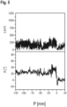
Fig. 5 undFig. 6 zeigen den Verlauf des Kristallwinkels und der Länge von Kanten-Facetten von einem Einkristall, der erfindungsgemäß hergestellt wurde. -
- 1
- Anfangskonus
- 2
- Kanten-Facette
- 3
- Oberflächen-Facette
- 4
- Meniskus
- 5
- Phasengrenze
- Ein Anfangskonus 1 mit einem Kristallwinkel κ, wie er in
Fig.1 schematisch dargestellt ist, weist typischerweise Kanten-Facetten 2 und gegebenenfalls Oberflächen-Facetten 3 auf. Die Kanten-Facetten 2 erstrecken sich vom Rand des Anfangskonus 1 entlang von {111}-Ebenen ins Innere. Der Schnittwinkel µ zwischen einer {111}-Ebene und einer Ebene senkrecht zur Wachstumsrichtung eines Einkristalls mit <100>-Orientierung hat den festen Wert von 54,7°. -
Fig.2 zeigt einen Anfangskonus 1 eines <100>-orientierten Einkristalls aus Silizium, der an einer Phasengrenze 5 zu einer Schmelze wächst. Die Phasengrenze 5 erstreckt sich zum Rand des Einkristalls bis zu einer Dreiphasengrenze TPB, wo am oberen Ende eines Meniskus 4 der Schmelze die flüssige Phase I, gebildet von der Schmelze, die feste Phase s, gebildet vom Einkristall, und die Gasphase g, gebildet von einer umgebenden Atmosphäre, aufeinandertreffen. Der Verlauf der Phasengrenze 5 repräsentiert näherungsweise auch den Verlauf einer Isotherme. Kanten-Facetten erstrecken sich entlang einer Richtung, die mit der Richtung der Ziehachse pd einen Winkel α von 35,3° bildet. Der Temperaturgradient Gf in Ausdehnungsrichtung einer Kanten-Facette sollte möglichst groß sein, damit die Länge der Kanten-Facette möglichst klein wird. Dementsprechend sollte der Krümmungswinkel θ zwischen der Richtung der Ziehachse und der Richtung des Temperaturgradienten Gs am Rand des Einkristalls 0° oder kleiner als 0° sein, besonders bevorzugt -35,3°. Der Temperaturgradient Gs erstreckt sich von der Phasengrenze 5 im rechten Winkel in den Einkristall und hat damit die Richtung entgegen der Wachstumsrichtung des Einkristalls. Die Temperaturgradienten Gf und Gs sowie der Krümmungswinkel θ stehen über die folgende Gleichung miteinander in Beziehung:
- Die Phasengrenze 5 hat, abweichend von der Darstellung gemäß
Fig.2 , möglichst eine Form, die, entgegen der Richtung der Ziehachse betrachtet, konkav gekrümmt, w-förmig, nahezu eben oder eben ist. Der Kristallwinkel κ beträgt in einem mittleren Abschnitt des Anfangskonus, dessen Länge nicht weniger als 50 % einer Länge des Anfangskonus beträgt, nicht weniger als 20° und nicht mehr als 30°. - In
Fig.3 ist der Temperaturgradient Gf über den Krümmungswinkel θ aufgetragen. Die Temperaturgradienten Gf und GS erreichen bei θ = -35,3° ein Maximum. - Eine Aufnahme gemäß
Fig.4 kann zur Bestimmung der Länge von Kanten-Facetten verwendet werden. Sie zeigt einen Teil des mittleren Abschnitts eines Anfangskonus. Zusätzlich eingezeichnet sind der Kristallwinkel κ und die Länge lf einer Kanten-Facette. -
Fig. 5 undFig.6 zeigen von einem Einkristall, der erfindungsgemäß hergestellt wurde, den Verlauf des Kristallwinkels κ und der Länge lf von Kanten-Facetten vom Beginn des Ziehens des mittleren Abschnitts des Anfangskonus bei Position P = -125 mm bis zum Ziehen der ersten 25 mm des zylindrischen Abschnitts des Einkristalls (Fig.5 ) und den entsprechenden Verlauf vom Beginn des Ziehens des zylindrischen Abschnitts (P = 0 mm) bis zum Ziehen der ersten 125 mm des zylindrischen Abschnitts des Einkristalls (Fig.6 ).
Claims (4)
- Verfahren zur Herstellung eines Einkristalls aus Silizium mit <100>-Orientierung, umfassenddas Dotieren einer Schmelze mit Dotierstoff vom n-Typ;das Ziehen eines Anfangskonus (1) mit einem Kristallwinkel κ, dem Winkel zwischen der <100>-Richtung, in die der Einkristall wächst, und einer Tangente, die am Rand des Einkristalls anliegt, eines zylindrischen Abschnitts und eines Endkonus des Einkristalls nach der CZ-Methode;das Ziehen des Anfangskonus mit dem Kristallwinkel κ von nicht weniger als 20° und nicht mehr als 30° in einem mittleren Abschnitt des Anfangskonus (1), dessen Länge nicht weniger als 50 % einer Länge des Anfangskonus (1) beträgt, wobei Schwankungen des Kristallwinkels κ mittels Winkelregelung auf nicht mehr als 0,01 °/s begrenzt werden; das Ziehen des zylindrischen Abschnitts des Einkristalls mit einer Ziehgeschwindigkeit, die nicht mehr als 75 % einer Grenzziehgeschwindigkeit beträgt, bei deren Überschreitung ein Verformen des Einkristalls eine Fortsetzung des Ziehens verhindert; unddas aktive Kühlen des Einkristalls im Bereich in der Nähe der Phasengrenze (5) zwischen dem wachsenden Einkristall und der Schmelze.
- Verfahren nach Anspruch 1, des Weiteren umfassend das Ziehen des Einkristalls in einem Übergangsbereich zwischen dem Anfangskonus (1) und dem zylindrischen Abschnitt mit einer Ziehgeschwindigkeit von nicht mehr als 1,5 mm/min.
- Verfahren nach Anspruch 1 oder Anspruch 2, wobei das Kühlen des Einkristalls mittels eines wassergekühlten Kühlers erfolgt.
- Verfahren nach einem der Ansprüche 1 bis 3, des Weiteren umfassend das Abtrennen der Halbleiterscheiben vom zylindrischen Abschnitt des Einkristalls.
Applications Claiming Priority (2)
| Application Number | Priority Date | Filing Date | Title |
|---|---|---|---|
| DE102017215332.6A DE102017215332A1 (de) | 2017-09-01 | 2017-09-01 | Einkristall aus Silizium mit <100>-Orientierung, der mit Dotierstoff vom n-Typ dotiert ist, und Verfahren zur Herstellung eines solchen Einkristalls |
| PCT/EP2018/073101 WO2019042979A1 (de) | 2017-09-01 | 2018-08-28 | Einkristall aus silizium mit <100>-orientierung, der mit dotierstoff vom n-typ dotiert ist, und verfahren zur herstellung eines solchen einkristalls |
Publications (2)
| Publication Number | Publication Date |
|---|---|
| EP3676425A1 EP3676425A1 (de) | 2020-07-08 |
| EP3676425B1 true EP3676425B1 (de) | 2023-10-04 |
Family
ID=63407219
Family Applications (1)
| Application Number | Title | Priority Date | Filing Date |
|---|---|---|---|
| EP18762067.9A Active EP3676425B1 (de) | 2017-09-01 | 2018-08-28 | Verfahren zur herstellung eines einkristalls aus silizium mit <100>-orientierung, der mit dotierstoff vom n-typ dotiert ist |
Country Status (10)
| Country | Link |
|---|---|
| US (1) | US11390962B2 (de) |
| EP (1) | EP3676425B1 (de) |
| JP (1) | JP6995980B2 (de) |
| KR (1) | KR102381014B1 (de) |
| CN (1) | CN111051578A (de) |
| DE (1) | DE102017215332A1 (de) |
| FI (1) | FI3676425T3 (de) |
| SG (1) | SG11202001640SA (de) |
| TW (1) | TWI668340B (de) |
| WO (1) | WO2019042979A1 (de) |
Family Cites Families (21)
| Publication number | Priority date | Publication date | Assignee | Title |
|---|---|---|---|---|
| JPS59102896A (ja) * | 1982-11-30 | 1984-06-14 | Toshiba Corp | 単結晶の形状制御方法 |
| JPH0644369B2 (ja) | 1982-12-28 | 1994-06-08 | オリンパス光学工業株式会社 | 磁気記録再生装置 |
| JPH05319988A (ja) * | 1992-05-25 | 1993-12-03 | Nippon Steel Corp | シリコン単結晶の製造方法 |
| US5769941A (en) * | 1996-05-01 | 1998-06-23 | Motorola, Inc. | Method of forming semiconductor material |
| JP3992800B2 (ja) * | 1997-09-22 | 2007-10-17 | Sumco Techxiv株式会社 | 単結晶製造装置および単結晶の製造方法 |
| JP3612974B2 (ja) * | 1997-12-26 | 2005-01-26 | 三菱住友シリコン株式会社 | 結晶育成方法 |
| US6241818B1 (en) | 1999-04-07 | 2001-06-05 | Memc Electronic Materials, Inc. | Method and system of controlling taper growth in a semiconductor crystal growth process |
| JP4357068B2 (ja) * | 1999-05-11 | 2009-11-04 | Sumco Techxiv株式会社 | 単結晶インゴット製造装置及び方法 |
| DE10025870A1 (de) | 2000-05-25 | 2001-12-06 | Wacker Siltronic Halbleitermat | Einkristallstab und Verfahren zur Herstellung desselben |
| JP3909675B2 (ja) * | 2001-04-20 | 2007-04-25 | 信越半導体株式会社 | シリコン単結晶の製造装置及びそれを用いたシリコン単結晶の製造方法 |
| WO2003091483A1 (fr) * | 2002-04-24 | 2003-11-06 | Shin-Etsu Handotai Co., Ltd. | Procede de production de silicium monocristallin, silicium monocristallin et plaquette de silicium |
| JP4089354B2 (ja) * | 2002-08-30 | 2008-05-28 | 株式会社Sumco | エピタキシャルウェーハとその製造方法 |
| JP4760729B2 (ja) * | 2006-02-21 | 2011-08-31 | 株式会社Sumco | Igbt用のシリコン単結晶ウェーハ及びigbt用のシリコン単結晶ウェーハの製造方法 |
| JP5463693B2 (ja) * | 2009-03-03 | 2014-04-09 | 信越半導体株式会社 | シリコンエピタキシャルウェーハの製造方法 |
| DE102009024473B4 (de) * | 2009-06-10 | 2015-11-26 | Siltronic Ag | Verfahren zum Ziehen eines Einkristalls aus Silizium und danach hergestellter Einkristall |
| KR101275382B1 (ko) * | 2010-03-02 | 2013-06-14 | 주식회사 엘지실트론 | 단결정 냉각장치 및 단결정 냉각장치를 포함하는 단결정 성장장치 |
| JP5831436B2 (ja) | 2012-12-11 | 2015-12-09 | 信越半導体株式会社 | シリコン単結晶の製造方法 |
| CN103343385A (zh) * | 2013-06-28 | 2013-10-09 | 浙江长兴众成电子有限公司 | 一种异形尺寸的直拉单晶硅及其生长方法 |
| FR3028266B1 (fr) * | 2014-11-10 | 2016-12-23 | Commissariat Energie Atomique | Procede de fabrication d'un lingot de silicium monocristallin de type n a concentration en donneurs thermiques a base d'oxygene controlee |
| JP6471492B2 (ja) * | 2014-12-24 | 2019-02-20 | 株式会社Sumco | 単結晶の製造方法 |
| JP6826536B2 (ja) * | 2015-10-23 | 2021-02-03 | 株式会社トクヤマ | シリコン単結晶インゴットの引上げ装置およびシリコン単結晶インゴットの製造方法 |
-
2017
- 2017-09-01 DE DE102017215332.6A patent/DE102017215332A1/de not_active Withdrawn
-
2018
- 2018-08-28 US US16/643,673 patent/US11390962B2/en active Active
- 2018-08-28 FI FIEP18762067.9T patent/FI3676425T3/fi active
- 2018-08-28 JP JP2020512371A patent/JP6995980B2/ja active Active
- 2018-08-28 CN CN201880055731.2A patent/CN111051578A/zh active Pending
- 2018-08-28 EP EP18762067.9A patent/EP3676425B1/de active Active
- 2018-08-28 KR KR1020207008044A patent/KR102381014B1/ko active Active
- 2018-08-28 WO PCT/EP2018/073101 patent/WO2019042979A1/de not_active Ceased
- 2018-08-28 SG SG11202001640SA patent/SG11202001640SA/en unknown
- 2018-08-29 TW TW107130081A patent/TWI668340B/zh active
Also Published As
| Publication number | Publication date |
|---|---|
| EP3676425A1 (de) | 2020-07-08 |
| SG11202001640SA (en) | 2020-03-30 |
| TWI668340B (zh) | 2019-08-11 |
| US20200270764A1 (en) | 2020-08-27 |
| KR20200042516A (ko) | 2020-04-23 |
| JP6995980B2 (ja) | 2022-02-03 |
| TW201912850A (zh) | 2019-04-01 |
| KR102381014B1 (ko) | 2022-04-01 |
| US11390962B2 (en) | 2022-07-19 |
| CN111051578A (zh) | 2020-04-21 |
| JP2020531401A (ja) | 2020-11-05 |
| FI3676425T3 (fi) | 2023-12-14 |
| WO2019042979A1 (de) | 2019-03-07 |
| DE102017215332A1 (de) | 2019-03-07 |
Similar Documents
| Publication | Publication Date | Title |
|---|---|---|
| DE69604235T2 (de) | Verfahren zur herstellung eines siliziumeinkristalles mit niediger fehlerdichte | |
| DE112018002156B4 (de) | Verfahren zur Herstellung eines Silicium-Einkristalls vom n-Typ, Silicium-Einkristall-Ingot vom n-Typ, Siliciumwafer und epitaktischer Siliciumwafer | |
| DE69913731T2 (de) | Im wesentlichen defektfreie epitaktische siliziumscheiben | |
| DE112014007334B3 (de) | Sauerstoffpräzipitation in stark dotierten Siliciumwafern, geschnitten aus nach dem Czochralski-Verfahren gezüchteten Ingots | |
| DE112014006413B4 (de) | Herstellungsverfahren für epitaktischen Siliciumwafer | |
| DE69902911T2 (de) | Widerstandsheizung fur eine kristallzüchtungsvorrichtung und verfahren zu ihrer verwendung | |
| DE112016001962T5 (de) | Verfahren zur Herstellung von Siliziumepitaxialwafern | |
| DE102010029741A1 (de) | Verfahren zum Herstellen von Silizium-Wafern und Silizium-Solarzelle | |
| DE112013001054T5 (de) | Verfahren zum Herstellen eines Silizium-Einkristall-Wafers | |
| DE112014002133T5 (de) | Herstellungsverfahren für einen Einkristall und Verfahren zur Herstellung von Siliciumwafer | |
| DE112014004719B4 (de) | Verfahren zum Herstellen eines Silizium-Einkristalls | |
| AT398582B (de) | Verfahren zur kristallzüchtung | |
| DE112015004143T5 (de) | Verfahren zum Herstellen eines Einkristalls und Verfahren zum Herstellen eines Siliziumwafers | |
| DE69802864T2 (de) | Silizium-Impfkristall, Verfahren zu seiner Herstellung und Verfahren zur Herstellung eines Silizium-Einkristalls unter Verwendung des Silizium-Impfkristalls | |
| DE102017217540A1 (de) | Herstellungsverfahren für einkristallines Silicium und einkristallines Silicium | |
| DE102009033667B4 (de) | Verfahren zum Züchten eines Halbleitereinkristalls und Vorrichtung zur Durchführung des Verfahrens | |
| DE60036359T2 (de) | Verbesserter silizium werkstoff vom typ-n für epitaxie-substrat und verfahren zu seiner herstellung | |
| DE112018001044T5 (de) | Verfahren zum Herstellen von Silizium-Einkristallbarren, und Silizium-Einkristall-Barren | |
| DE2654945A1 (de) | Verfahren zur herstellung von im wesentlichen einkristallinen baendern zur verwendung bei der herstellung elektronischer festkoerperanordnungen, insbesondere bei der herstellung von solarzellen | |
| DE112018006080T5 (de) | Silicium-Einkristall, Verfahren zur Herstellung desselben, sowie Siliciumwafer | |
| DE69719527T2 (de) | VERFAHREN ZUM DOTIEREN EINES BEREICHES MIT BOR IN EINER SiC-SCHICHT | |
| DE112018003320T5 (de) | Verfahren zur Herstellung von Silizium-Einkristall | |
| DE112017003016T5 (de) | Verfahren zur Herstellung von Silicium-Einkristall | |
| DE102004039197A1 (de) | Verfahren zur Herstellung von dotierten Halbleiterscheiben aus Silizium und derartige Halbleiterscheiben | |
| DE10392918T5 (de) | Verfahren zur Herstellung eines Einkristallhalbleiters und Vorrichtung zur Herstellung eines Einkristallhalbleiters |
Legal Events
| Date | Code | Title | Description |
|---|---|---|---|
| STAA | Information on the status of an ep patent application or granted ep patent |
Free format text: STATUS: UNKNOWN |
|
| STAA | Information on the status of an ep patent application or granted ep patent |
Free format text: STATUS: THE INTERNATIONAL PUBLICATION HAS BEEN MADE |
|
| PUAI | Public reference made under article 153(3) epc to a published international application that has entered the european phase |
Free format text: ORIGINAL CODE: 0009012 |
|
| STAA | Information on the status of an ep patent application or granted ep patent |
Free format text: STATUS: REQUEST FOR EXAMINATION WAS MADE |
|
| 17P | Request for examination filed |
Effective date: 20200226 |
|
| AK | Designated contracting states |
Kind code of ref document: A1 Designated state(s): AL AT BE BG CH CY CZ DE DK EE ES FI FR GB GR HR HU IE IS IT LI LT LU LV MC MK MT NL NO PL PT RO RS SE SI SK SM TR |
|
| AX | Request for extension of the european patent |
Extension state: BA ME |
|
| RIN1 | Information on inventor provided before grant (corrected) |
Inventor name: STOCKMEIER, LUDWIG Inventor name: FRIEDRICH, JOCHEN Inventor name: MILLER, ALFRED Inventor name: DANIEL, MATTHIAS Inventor name: RAMING, GEORG |
|
| DAV | Request for validation of the european patent (deleted) | ||
| DAX | Request for extension of the european patent (deleted) | ||
| RAP1 | Party data changed (applicant data changed or rights of an application transferred) |
Owner name: SILTRONIC AG |
|
| STAA | Information on the status of an ep patent application or granted ep patent |
Free format text: STATUS: EXAMINATION IS IN PROGRESS |
|
| 17Q | First examination report despatched |
Effective date: 20210430 |
|
| GRAP | Despatch of communication of intention to grant a patent |
Free format text: ORIGINAL CODE: EPIDOSNIGR1 |
|
| STAA | Information on the status of an ep patent application or granted ep patent |
Free format text: STATUS: GRANT OF PATENT IS INTENDED |
|
| INTG | Intention to grant announced |
Effective date: 20230418 |
|
| GRAS | Grant fee paid |
Free format text: ORIGINAL CODE: EPIDOSNIGR3 |
|
| GRAA | (expected) grant |
Free format text: ORIGINAL CODE: 0009210 |
|
| STAA | Information on the status of an ep patent application or granted ep patent |
Free format text: STATUS: THE PATENT HAS BEEN GRANTED |
|
| AK | Designated contracting states |
Kind code of ref document: B1 Designated state(s): AL AT BE BG CH CY CZ DE DK EE ES FI FR GB GR HR HU IE IS IT LI LT LU LV MC MK MT NL NO PL PT RO RS SE SI SK SM TR |
|
| REG | Reference to a national code |
Ref country code: GB Ref legal event code: FG4D Free format text: NOT ENGLISH |
|
| REG | Reference to a national code |
Ref country code: CH Ref legal event code: EP |
|
| REG | Reference to a national code |
Ref country code: IE Ref legal event code: FG4D Free format text: LANGUAGE OF EP DOCUMENT: GERMAN |
|
| REG | Reference to a national code |
Ref country code: DE Ref legal event code: R096 Ref document number: 502018013394 Country of ref document: DE |
|
| REG | Reference to a national code |
Ref country code: FI Ref legal event code: FGE |
|
| REG | Reference to a national code |
Ref country code: LT Ref legal event code: MG9D |
|
| REG | Reference to a national code |
Ref country code: NL Ref legal event code: MP Effective date: 20231004 |
|
| PG25 | Lapsed in a contracting state [announced via postgrant information from national office to epo] |
Ref country code: NL Free format text: LAPSE BECAUSE OF FAILURE TO SUBMIT A TRANSLATION OF THE DESCRIPTION OR TO PAY THE FEE WITHIN THE PRESCRIBED TIME-LIMIT Effective date: 20231004 |
|
| PG25 | Lapsed in a contracting state [announced via postgrant information from national office to epo] |
Ref country code: GR Free format text: LAPSE BECAUSE OF FAILURE TO SUBMIT A TRANSLATION OF THE DESCRIPTION OR TO PAY THE FEE WITHIN THE PRESCRIBED TIME-LIMIT Effective date: 20240105 |
|
| PG25 | Lapsed in a contracting state [announced via postgrant information from national office to epo] |
Ref country code: IS Free format text: LAPSE BECAUSE OF FAILURE TO SUBMIT A TRANSLATION OF THE DESCRIPTION OR TO PAY THE FEE WITHIN THE PRESCRIBED TIME-LIMIT Effective date: 20240204 |
|
| PG25 | Lapsed in a contracting state [announced via postgrant information from national office to epo] |
Ref country code: LT Free format text: LAPSE BECAUSE OF FAILURE TO SUBMIT A TRANSLATION OF THE DESCRIPTION OR TO PAY THE FEE WITHIN THE PRESCRIBED TIME-LIMIT Effective date: 20231004 |
|
| PG25 | Lapsed in a contracting state [announced via postgrant information from national office to epo] |
Ref country code: ES Free format text: LAPSE BECAUSE OF FAILURE TO SUBMIT A TRANSLATION OF THE DESCRIPTION OR TO PAY THE FEE WITHIN THE PRESCRIBED TIME-LIMIT Effective date: 20231004 |
|
| PG25 | Lapsed in a contracting state [announced via postgrant information from national office to epo] |
Ref country code: LT Free format text: LAPSE BECAUSE OF FAILURE TO SUBMIT A TRANSLATION OF THE DESCRIPTION OR TO PAY THE FEE WITHIN THE PRESCRIBED TIME-LIMIT Effective date: 20231004 Ref country code: IS Free format text: LAPSE BECAUSE OF FAILURE TO SUBMIT A TRANSLATION OF THE DESCRIPTION OR TO PAY THE FEE WITHIN THE PRESCRIBED TIME-LIMIT Effective date: 20240204 Ref country code: GR Free format text: LAPSE BECAUSE OF FAILURE TO SUBMIT A TRANSLATION OF THE DESCRIPTION OR TO PAY THE FEE WITHIN THE PRESCRIBED TIME-LIMIT Effective date: 20240105 Ref country code: ES Free format text: LAPSE BECAUSE OF FAILURE TO SUBMIT A TRANSLATION OF THE DESCRIPTION OR TO PAY THE FEE WITHIN THE PRESCRIBED TIME-LIMIT Effective date: 20231004 Ref country code: BG Free format text: LAPSE BECAUSE OF FAILURE TO SUBMIT A TRANSLATION OF THE DESCRIPTION OR TO PAY THE FEE WITHIN THE PRESCRIBED TIME-LIMIT Effective date: 20240104 Ref country code: PT Free format text: LAPSE BECAUSE OF FAILURE TO SUBMIT A TRANSLATION OF THE DESCRIPTION OR TO PAY THE FEE WITHIN THE PRESCRIBED TIME-LIMIT Effective date: 20240205 |
|
| PG25 | Lapsed in a contracting state [announced via postgrant information from national office to epo] |
Ref country code: SE Free format text: LAPSE BECAUSE OF FAILURE TO SUBMIT A TRANSLATION OF THE DESCRIPTION OR TO PAY THE FEE WITHIN THE PRESCRIBED TIME-LIMIT Effective date: 20231004 Ref country code: RS Free format text: LAPSE BECAUSE OF FAILURE TO SUBMIT A TRANSLATION OF THE DESCRIPTION OR TO PAY THE FEE WITHIN THE PRESCRIBED TIME-LIMIT Effective date: 20231004 Ref country code: PL Free format text: LAPSE BECAUSE OF FAILURE TO SUBMIT A TRANSLATION OF THE DESCRIPTION OR TO PAY THE FEE WITHIN THE PRESCRIBED TIME-LIMIT Effective date: 20231004 Ref country code: NO Free format text: LAPSE BECAUSE OF FAILURE TO SUBMIT A TRANSLATION OF THE DESCRIPTION OR TO PAY THE FEE WITHIN THE PRESCRIBED TIME-LIMIT Effective date: 20240104 Ref country code: LV Free format text: LAPSE BECAUSE OF FAILURE TO SUBMIT A TRANSLATION OF THE DESCRIPTION OR TO PAY THE FEE WITHIN THE PRESCRIBED TIME-LIMIT Effective date: 20231004 Ref country code: HR Free format text: LAPSE BECAUSE OF FAILURE TO SUBMIT A TRANSLATION OF THE DESCRIPTION OR TO PAY THE FEE WITHIN THE PRESCRIBED TIME-LIMIT Effective date: 20231004 |
|
| REG | Reference to a national code |
Ref country code: DE Ref legal event code: R097 Ref document number: 502018013394 Country of ref document: DE |
|
| PG25 | Lapsed in a contracting state [announced via postgrant information from national office to epo] |
Ref country code: DK Free format text: LAPSE BECAUSE OF FAILURE TO SUBMIT A TRANSLATION OF THE DESCRIPTION OR TO PAY THE FEE WITHIN THE PRESCRIBED TIME-LIMIT Effective date: 20231004 |
|
| PG25 | Lapsed in a contracting state [announced via postgrant information from national office to epo] |
Ref country code: CZ Free format text: LAPSE BECAUSE OF FAILURE TO SUBMIT A TRANSLATION OF THE DESCRIPTION OR TO PAY THE FEE WITHIN THE PRESCRIBED TIME-LIMIT Effective date: 20231004 |
|
| PG25 | Lapsed in a contracting state [announced via postgrant information from national office to epo] |
Ref country code: SK Free format text: LAPSE BECAUSE OF FAILURE TO SUBMIT A TRANSLATION OF THE DESCRIPTION OR TO PAY THE FEE WITHIN THE PRESCRIBED TIME-LIMIT Effective date: 20231004 |
|
| PG25 | Lapsed in a contracting state [announced via postgrant information from national office to epo] |
Ref country code: SM Free format text: LAPSE BECAUSE OF FAILURE TO SUBMIT A TRANSLATION OF THE DESCRIPTION OR TO PAY THE FEE WITHIN THE PRESCRIBED TIME-LIMIT Effective date: 20231004 Ref country code: SK Free format text: LAPSE BECAUSE OF FAILURE TO SUBMIT A TRANSLATION OF THE DESCRIPTION OR TO PAY THE FEE WITHIN THE PRESCRIBED TIME-LIMIT Effective date: 20231004 Ref country code: RO Free format text: LAPSE BECAUSE OF FAILURE TO SUBMIT A TRANSLATION OF THE DESCRIPTION OR TO PAY THE FEE WITHIN THE PRESCRIBED TIME-LIMIT Effective date: 20231004 Ref country code: EE Free format text: LAPSE BECAUSE OF FAILURE TO SUBMIT A TRANSLATION OF THE DESCRIPTION OR TO PAY THE FEE WITHIN THE PRESCRIBED TIME-LIMIT Effective date: 20231004 Ref country code: DK Free format text: LAPSE BECAUSE OF FAILURE TO SUBMIT A TRANSLATION OF THE DESCRIPTION OR TO PAY THE FEE WITHIN THE PRESCRIBED TIME-LIMIT Effective date: 20231004 Ref country code: CZ Free format text: LAPSE BECAUSE OF FAILURE TO SUBMIT A TRANSLATION OF THE DESCRIPTION OR TO PAY THE FEE WITHIN THE PRESCRIBED TIME-LIMIT Effective date: 20231004 |
|
| PLBE | No opposition filed within time limit |
Free format text: ORIGINAL CODE: 0009261 |
|
| STAA | Information on the status of an ep patent application or granted ep patent |
Free format text: STATUS: NO OPPOSITION FILED WITHIN TIME LIMIT |
|
| 26N | No opposition filed |
Effective date: 20240705 |
|
| PG25 | Lapsed in a contracting state [announced via postgrant information from national office to epo] |
Ref country code: SI Free format text: LAPSE BECAUSE OF FAILURE TO SUBMIT A TRANSLATION OF THE DESCRIPTION OR TO PAY THE FEE WITHIN THE PRESCRIBED TIME-LIMIT Effective date: 20231004 |
|
| PG25 | Lapsed in a contracting state [announced via postgrant information from national office to epo] |
Ref country code: SI Free format text: LAPSE BECAUSE OF FAILURE TO SUBMIT A TRANSLATION OF THE DESCRIPTION OR TO PAY THE FEE WITHIN THE PRESCRIBED TIME-LIMIT Effective date: 20231004 |
|
| REG | Reference to a national code |
Ref country code: CH Ref legal event code: PL |
|
| PG25 | Lapsed in a contracting state [announced via postgrant information from national office to epo] |
Ref country code: LU Free format text: LAPSE BECAUSE OF NON-PAYMENT OF DUE FEES Effective date: 20240828 |
|
| GBPC | Gb: european patent ceased through non-payment of renewal fee |
Effective date: 20240828 |
|
| PG25 | Lapsed in a contracting state [announced via postgrant information from national office to epo] |
Ref country code: CH Free format text: LAPSE BECAUSE OF NON-PAYMENT OF DUE FEES Effective date: 20240831 Ref country code: MC Free format text: LAPSE BECAUSE OF FAILURE TO SUBMIT A TRANSLATION OF THE DESCRIPTION OR TO PAY THE FEE WITHIN THE PRESCRIBED TIME-LIMIT Effective date: 20231004 |
|
| REG | Reference to a national code |
Ref country code: BE Ref legal event code: MM Effective date: 20240831 |
|
| PG25 | Lapsed in a contracting state [announced via postgrant information from national office to epo] |
Ref country code: GB Free format text: LAPSE BECAUSE OF NON-PAYMENT OF DUE FEES Effective date: 20240828 |
|
| PG25 | Lapsed in a contracting state [announced via postgrant information from national office to epo] |
Ref country code: BE Free format text: LAPSE BECAUSE OF NON-PAYMENT OF DUE FEES Effective date: 20240831 |
|
| PG25 | Lapsed in a contracting state [announced via postgrant information from national office to epo] |
Ref country code: FR Free format text: LAPSE BECAUSE OF NON-PAYMENT OF DUE FEES Effective date: 20240831 |
|
| PG25 | Lapsed in a contracting state [announced via postgrant information from national office to epo] |
Ref country code: IE Free format text: LAPSE BECAUSE OF NON-PAYMENT OF DUE FEES Effective date: 20240828 |
|
| PGFP | Annual fee paid to national office [announced via postgrant information from national office to epo] |
Ref country code: FI Payment date: 20250822 Year of fee payment: 8 |
|
| PGFP | Annual fee paid to national office [announced via postgrant information from national office to epo] |
Ref country code: DE Payment date: 20250820 Year of fee payment: 8 |
|
| PGFP | Annual fee paid to national office [announced via postgrant information from national office to epo] |
Ref country code: IT Payment date: 20250825 Year of fee payment: 8 |
|
| REG | Reference to a national code |
Ref country code: AT Ref legal event code: MM01 Ref document number: 1617851 Country of ref document: AT Kind code of ref document: T Effective date: 20240828 |
|
| PG25 | Lapsed in a contracting state [announced via postgrant information from national office to epo] |
Ref country code: AT Free format text: LAPSE BECAUSE OF NON-PAYMENT OF DUE FEES Effective date: 20240828 |
|
| PG25 | Lapsed in a contracting state [announced via postgrant information from national office to epo] |
Ref country code: CY Free format text: LAPSE BECAUSE OF FAILURE TO SUBMIT A TRANSLATION OF THE DESCRIPTION OR TO PAY THE FEE WITHIN THE PRESCRIBED TIME-LIMIT; INVALID AB INITIO Effective date: 20180828 |
|
| PG25 | Lapsed in a contracting state [announced via postgrant information from national office to epo] |
Ref country code: HU Free format text: LAPSE BECAUSE OF FAILURE TO SUBMIT A TRANSLATION OF THE DESCRIPTION OR TO PAY THE FEE WITHIN THE PRESCRIBED TIME-LIMIT; INVALID AB INITIO Effective date: 20180828 |