EP3675618B1 - Steuerungssystem für bandzuführvorrichtung - Google Patents
Steuerungssystem für bandzuführvorrichtung Download PDFInfo
- Publication number
- EP3675618B1 EP3675618B1 EP17922756.6A EP17922756A EP3675618B1 EP 3675618 B1 EP3675618 B1 EP 3675618B1 EP 17922756 A EP17922756 A EP 17922756A EP 3675618 B1 EP3675618 B1 EP 3675618B1
- Authority
- EP
- European Patent Office
- Prior art keywords
- tape
- remaining amount
- amount information
- component
- reel
- Prior art date
- Legal status (The legal status is an assumption and is not a legal conclusion. Google has not performed a legal analysis and makes no representation as to the accuracy of the status listed.)
- Active
Links
Images


Classifications
-
- H—ELECTRICITY
- H05—ELECTRIC TECHNIQUES NOT OTHERWISE PROVIDED FOR
- H05K—PRINTED CIRCUITS; CASINGS OR CONSTRUCTIONAL DETAILS OF ELECTRIC APPARATUS; MANUFACTURE OF ASSEMBLAGES OF ELECTRICAL COMPONENTS
- H05K13/00—Apparatus or processes specially adapted for manufacturing or adjusting assemblages of electric components
- H05K13/08—Monitoring manufacture of assemblages
- H05K13/086—Supply management, e.g. supply of components or of substrates
-
- H—ELECTRICITY
- H05—ELECTRIC TECHNIQUES NOT OTHERWISE PROVIDED FOR
- H05K—PRINTED CIRCUITS; CASINGS OR CONSTRUCTIONAL DETAILS OF ELECTRIC APPARATUS; MANUFACTURE OF ASSEMBLAGES OF ELECTRICAL COMPONENTS
- H05K13/00—Apparatus or processes specially adapted for manufacturing or adjusting assemblages of electric components
- H05K13/08—Monitoring manufacture of assemblages
- H05K13/0882—Control systems for mounting machines or assembly lines, e.g. centralized control, remote links, programming of apparatus and processes as such
-
- G—PHYSICS
- G05—CONTROLLING; REGULATING
- G05B—CONTROL OR REGULATING SYSTEMS IN GENERAL; FUNCTIONAL ELEMENTS OF SUCH SYSTEMS; MONITORING OR TESTING ARRANGEMENTS FOR SUCH SYSTEMS OR ELEMENTS
- G05B13/00—Adaptive control systems, i.e. systems automatically adjusting themselves to have a performance which is optimum according to some preassigned criterion
- G05B13/02—Adaptive control systems, i.e. systems automatically adjusting themselves to have a performance which is optimum according to some preassigned criterion electric
- G05B13/0205—Adaptive control systems, i.e. systems automatically adjusting themselves to have a performance which is optimum according to some preassigned criterion electric not using a model or a simulator of the controlled system
- G05B13/024—Adaptive control systems, i.e. systems automatically adjusting themselves to have a performance which is optimum according to some preassigned criterion electric not using a model or a simulator of the controlled system in which a parameter or coefficient is automatically adjusted to optimise the performance
-
- H—ELECTRICITY
- H05—ELECTRIC TECHNIQUES NOT OTHERWISE PROVIDED FOR
- H05K—PRINTED CIRCUITS; CASINGS OR CONSTRUCTIONAL DETAILS OF ELECTRIC APPARATUS; MANUFACTURE OF ASSEMBLAGES OF ELECTRICAL COMPONENTS
- H05K13/00—Apparatus or processes specially adapted for manufacturing or adjusting assemblages of electric components
- H05K13/02—Feeding of components
-
- H—ELECTRICITY
- H05—ELECTRIC TECHNIQUES NOT OTHERWISE PROVIDED FOR
- H05K—PRINTED CIRCUITS; CASINGS OR CONSTRUCTIONAL DETAILS OF ELECTRIC APPARATUS; MANUFACTURE OF ASSEMBLAGES OF ELECTRICAL COMPONENTS
- H05K13/00—Apparatus or processes specially adapted for manufacturing or adjusting assemblages of electric components
- H05K13/04—Mounting of components, e.g. of leadless components
- H05K13/0417—Feeding with belts or tapes
- H05K13/0419—Feeding with belts or tapes tape feeders
Definitions
- the present specification discloses technology relating to a control system of a tape feeder for drawing a component supply tape from a reel on which a component supply tape is wound and pitch feeding the component supply tape to a component pickup position.
- a tape feeder includes a reel on which a component supply tape, in which components are packaged by being arranged at a predetermined pitch, is wound, and a tape feeding device that draws out the component supply tape from the reel and feeds the leading component of the component supply tape to a component pickup position where the leading component is picked up by a suction nozzle of the component mounter.
- the rotation speed and the rotation amount of the motor serving as the drive source of the tape supply device are changed in accordance with the type of the component supply tape used (the type of the component), and the tape feeding speed and the pitch feeding amount are changed in accordance with the type of the component supply tape.
- Patent Literature 2 provides a further control system of a tape feeder according to the prior art.
- the force (load of motor) required for a tape feeding device to draw the component supply tape from the reel decreases as the remaining quantity of tape on the reel (component remaining quantity) decreases. Therefore, as the motor of the tape feeding device, a motor is used that generates the torque required to stably pitch feed the component supply tape even when the tape remaining quantity of the reel is large and the load is large.
- the tape feeding rate may become slow due to insufficient torque of the motor when the remaining tape level of the reel is large, or the motor may become out of step such that the component supply tape cannot be stably fed.
- a control system of a tape feeder that includes a reel on which is wound component supply tape in which components are packaged by being arranged in a line, and a tape feeding device configured to draw out the component supply tape from the reel and pitch feed the component supply tape such that a leading component in the component supply tape is moved to a component pickup position to be picked up by a suction nozzle of a component mounter
- the control system including: a tape remaining amount information acquiring section configured to acquire tape remaining amount information that is information relating to a remaining amount of the tape on the reel; an auxiliary actuator configured to reinforce drive power to pitch feeding operation of the component supply tape by the tape feeding device and a control section configured to change an operation parameter of the auxiliary actuator and a motor that is a drive source of the tape feeding device based on the tape remaining amount information acquired by the tape remaining amount information acquiring section.
- the tape remaining amount acquiring section for example, it is possible to perform control to change, as an operation parameter of the motor or the auxiliary actuator (for example, a speed profile or a drive current of a pitch feeding operation), a torque of the motor or the auxiliary actuator so as to decrease continuously or in steps in accordance with a decrease in the load on the motor as the tape remaining amount on the reel decreases, enabling a reduction in the power consumption of the motor without losing stability in tape feeding operation, thus achieving both goals of motor energy saving and stable tape feeding operation.
- an operation parameter of the motor or the auxiliary actuator for example, a speed profile or a drive current of a pitch feeding operation
- the auxiliary actuator for reinforcing the drive power to pitch feeding operation of the component supply tape by the tape feeding device is provided, it is sufficient to use a motor whose torque is smaller by an amount corresponding to the output of the auxiliary actuator as the motor of the tape feeding device.
- a first embodiment will be described with reference to figs. 1 to 4 .
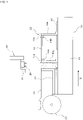
- component mounter 10 will be described with reference to fig. 1 .
- At least one component mounter 10 is installed in a component mounting line for producing a component-mounted board.
- Conveyor 13 that conveys circuit board 12 is provided on base 11 of component mounter 10 (below, the conveyance direction of circuit board 12 by conveyor 13 is referred to as the X direction, and the direction perpendicular to that is referred to as the Y direction).
- support member 15a that support the two conveyor rails 13a and 13b and conveyor belts 14a and 14b that configure conveyor 13
- support member 15a is fixed at a specified position, with the support member 15b on the opposite side being adjusted in the Y direction along guide rail 16 by a screw mechanism (not shown) or the like such that the width of conveyor 13 (the gap between conveyor rails 13a and 13b) is adjustable to the width of circuit board 12.
- feeder setting table 22 is provided to the side of conveyor 13 on base 11, with multiple tape feeders 23 being removably set on feeder setting table 22 in the Y direction.
- Set on each tape feeder 23 is component supply tape 24 (see fig. 2 ) on which is wound component supply tape housing many components at a fixed pitch, with the component supply tape 24 being set such that the leading component of the component supply tape pulled from the component supply tape 24 is positioned at a component pickup position (position at which the component is picked up by suction nozzle 26).
- Component mounter 10 is provided with head moving device 28 for moving mounting head 27 that holds suction nozzle 26 in the following order: component pickup position --> component imaging position --> component mounting position, and during component pickup operation and component mounting operation, suction nozzle 26 is raised and lowered.
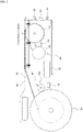
- tape feeder 23 is provided with tape feeding device 31 that draws out component supply tape 24 from reel 25 and pitch feeds it.
- Tape feeding device 31 is configured including: sprocket 32 that rotates to pitch feed with teeth engaged with feeding holes formed at equal pitches on one edge of tape feeder 23; motor 33 that serves as a drive source; and gear mechanism 34 that transmits the rotational force of motor 33 to sprocket 32 so as to rotate sprocket 32.
- motor 33 for motor 33, a motor, for example, a stepping motor, a servo motor, or the like, capable of controlling the rotation angle (rotation position) is used to perform the pitch feeding operation of component supply tape 24.
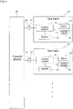
- tape feeder 23 Provided on the back end surface of tape feeder 23 are two positioning pins 35 for determining the mounting position with respect to component mounter 10, and connector 37 for both communication and power supply, which is connected to connector 36 (see fig. 3 ) on the component mounter 10 side.
- Power is supplied from component mounter 10 to tape feeder 23 by connecting connectors 36 and 37, and control section 41 (motor control section) of tape feeder 23 and control device 40 of component mounter 10 are connected so as to be able to communicate with each other.
- Control section 41 of tape feeder 23 controls the operation of motor 33 of tape feeding device 31 based on a pitch feed command transmitted from control device 40 of component mounter 10 to control the pitch feeding operation of component supply tape 24.
- tape feeder 23 is provided with sensor 42 (tape remaining amount data acquiring section) for detecting the tape remaining amount of reel 25.
- Sensor 42 is configured using, for example, an ultrasonic sensor, an optical sensor, or the like, and detects the winding diameter of component supply tape 24 of reel 25 as the tape remaining amount information, and outputs the detected information to control section 41 of tape feeder 23.
- Control section 41 of tape feeder 23 functions as a motor control section for changing an operation parameter of motor 33 of tape feeder 31 based on the tape remaining amount information detected by sensor 42.
- control section 41 of tape feeder 23 changes the operation parameter of tape feeder 33 so as to continuously or in steps decrease the torque of motor 33 as the tape remaining amount of reel 25 decreases and the load of motor 33 decreases, based on the tape remaining amount information detected by sensor 42.
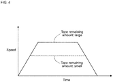
- the operation parameter of motor 33 to be changed based on the tape remaining amount information is, for example, the speed profile of the pitch feeding operation (see fig. 4 ), and the maximum speed of the speed profile is continuously or in steps decreased as the tape remaining amount of reel 25 decreases.
- the torque of motor 33 and thus the power consumption can be controlled to be continuously or in steps reduced, and the power consumption of motor 33 can be reduced without impairing the stability of the tape feeding operation, thus achieving both goals of motor 33 energy saving and stable tape feeding operation.
- operation parameter of motor 33 to be changed based on the tape remaining amount information is not limited to the speed profile of the pitch feeding operation, and for example, considering that the drive current of motor 33 and the torque are proportional to each other, control section 41 of tape feeder 23 may be configured to control the drive current of motor 33 to be continuously or in steps reduced as the tape remaining amount of reel 25 decreases. In this case too, as the tape remaining amount of reel 25 decreases, the torque of motor 33, and thus the consumed power, can be controlled so as to be continuously or in steps reduced, thus achieving both goals of motor 33 energy saving and stable tape feeding operation.
- Tape feeder 23 of the second embodiment is provided with auxiliary actuator 50 for reinforcing the drive power of the pitch feeding operation of component supply tape 24 by tape feeding device 31.
- Auxiliary actuator 50 is provided to transmit a rotational force in the pitch feeding direction to reel 25 in synchronization with the pitch feeding operation of component supply tape 24 by tape feeding device 31.
- auxiliary actuator 50 is configured from, for example, an outer rotor type motor, and the outer peripheral surface of the auxiliary actuator 50a contacts the outer peripheral edge of reel 25 so as to apply a rotational force in the pitch feeding direction to reel 25.
- a high friction elastic member such as rubber having a relatively large friction coefficient may be provided on the outer peripheral surface of rotor 50a, and the high friction elastic member may contact the outer peripheral edge of reel 25 to prevent slippage between rotor 50a and reel 25.
- control section 41 of tape feeder 23 functions as a motor control section for controlling the operation of motor 33 of tape feeding device 31, and also functions as an auxiliary actuator control section for changing the operation parameter of auxiliary actuator 50 based on the tape remaining amount information detected by sensor 42.
- control section 41 of tape feeder 23 changes the operation parameter of the auxiliary actuator 50 so as to continuously or in steps decrease the output of auxiliary actuator 50 as the tape remaining amount of reel 25 decreases and the load of motor 33 decreases, based on the tape remaining amount information detected by sensor 42.
- the operation parameter of auxiliary actuator 50 to be changed based on the tape remaining amount information is, for example, a speed profile, a drive current, or the like.
- tape feeder 23 of the second embodiment is provided with auxiliary actuator 50 for reinforcing the drive power to pitch feeding operation of the component supply tape by tape feeding device 31, it is sufficient to use a motor whose torque is smaller by an amount corresponding to the output the auxiliary actuator 50 as motor 33 of tape feeding device 31.
- a motor whose torque is smaller by an amount corresponding to the output the auxiliary actuator 50 as motor 33 of tape feeding device 31.
- auxiliary actuator 50 the configuration to rotate reel 25 by auxiliary actuator 50 may be changed as appropriate, and for example, the rotational force of the auxiliary actuator may be transmitted to reel 25 via a rotational transmission mechanism such as a gear mechanism or a belt transmission mechanism.
- a device for applying a tensile force to component supply tape 24 drawn out from reel 25 may be driven by an auxiliary actuator, in other words, an auxiliary actuator for reinforcing the drive power of the pitch feeding operation of component supply tape 24 by tape feeding device 31 may be provided.
- the configuration is such that sensor 42 for detecting the tape remaining amount of reel 25 is provided as the tape remaining amount information acquiring section, but sensor 42 may be omitted, and control section 41 of tape feeder 23 may function as the tape remaining amount information acquiring section, and may calculate the rotation amount of motor 33 or the feeding amount of component supply tape 24 from the first pitch feeding operation of component supply tape 24, and function as the tape feeding information acquiring section that uses the calculated value as the tape feeding information, with control section 41 of tape feeder 23 calculating the tape remaining amount information based on the tape feeding information.
- control device 40 of component mounter 10 may manage a component remaining quantity of tape feeder 23 by counting components picked up by suction nozzle 26 from tape feeder 23, and control device 41 (tape remaining amount information acquiring section) of tape feeder 23 may acquire the component remaining quantity of tape feeder 23 from control device 40 of component mounter 10 as the tape remaining amount information.
Landscapes
- Engineering & Computer Science (AREA)
- Microelectronics & Electronic Packaging (AREA)
- Manufacturing & Machinery (AREA)
- Automation & Control Theory (AREA)
- Operations Research (AREA)
- Computer Vision & Pattern Recognition (AREA)
- Software Systems (AREA)
- Physics & Mathematics (AREA)
- General Physics & Mathematics (AREA)
- Medical Informatics (AREA)
- Evolutionary Computation (AREA)
- Health & Medical Sciences (AREA)
- Artificial Intelligence (AREA)
- Supply And Installment Of Electrical Components (AREA)
Claims (9)
- Ein Steuerungssystem für eine Bandzuführvorrichtung (23) umfassend, eine Spule (25), auf der ein Bauteilzuführband (24) aufgewickelt ist, in dem Bauteile verpackt sind, indem sie in einer Reihe angeordnet sind, und eine Bandzuführvorrichtung (31), die konfiguriert ist, dass sie das Bauteilzuführband (24) von der Spule (25) abzieht und das Bauteilzuführband (24) mit einer solchen Teilung zuführt, dass ein führendes Bauteil in dem Bauteilzuführband (24) zu einer Bauteilaufnahmeposition bewegt wird, um von einer Saugdüse (26) einer Bauteilmontagevorrichtung aufgenommen zu werden, wobei das Steuersystem umfasst:
einen Bandrestmengeninformationserfassungsabschnitt (41), der konfiguriert ist, um Bandrestmengeninformationen zu erfassen, die sich auf eine Restmenge des Bandes auf der Spule (25) beziehen; gekennzeichnet durch:ein Hilfsstellglied (50), das konfiguriert ist, dass es die Antriebsleistung für den Vorschub des Bauteilzuführbands (24) durch die Bandzuführvorrichtung (31) verstärkt;einen Steuerabschnitt (41), der konfiguriert ist, einen Betriebsparameter des Hilfsstellglieds (50) und eines Motors (33), der eine Antriebsquelle der Bandzuführvorrichtung (31) ist, auf der Grundlage der Bandrestmengeninformation, die durch den Bandrestmengeninformationserfassungsabschnitt (41) erfasst wird, zu ändern. - Das Steuerungssystem für eine Bandzuführvorrichtung (23) gemäß Anspruch 1, wobei
der Steuerabschnitt (41) konfiguriert ist als Betriebsparameter des Motors (33) ein Drehmoment des Motors (33) zu ändern, das in Übereinstimmung mit der Bandrestmenge der Spule (25), die abnimmt, niedriger ist, basierend auf der Bandrestmengeninformation, die durch den Bandrestmengeninformationserfassungsabschnitt (41) erfasst wird. - Das Steuerungssystem für eine Bandzuführvorrichtung (23) gemäß Anspruch 1 oder 2, wobei
der Steuerabschnitt (41) konfiguriert ist als Betriebsparameter des Motors (33) ein Geschwindigkeitsprofil des Teilungsvorschubvorgangs auf der Grundlage der durch den Bandrestmengeninformationserfassungsabschnitt (41) erfassten Bandrestmengeninformationen zu ändern. - Das Steuerungssystem für eine Bandzuführvorrichtung (23) gemäß Anspruch 1 oder 2, wobei
der Steuerabschnitt (41) konfiguriert ist als Betriebsparameter des Motors (33) einen Antriebsstrom auf der Grundlage der von dem Bandrestmengeninformationserfassungsabschnitt (41) erfassten Bandrestmengeninformation ändert. - Das Steuerungssystem für eine Bandzuführvorrichtung (23) gemäß Anspruch 1, wobei
der Hilfsaktuator (50) konfiguriert ist, eine Drehkraft in einer Teilungsvorschubrichtung auf die Spule (25) synchron mit dem Teilungsvorschubvorgang des Bauteilzuführbandes (24) durch die Bandzuführvorrichtung (31) zu übertragen. - Das Steuerungssystem für eine Bandzuführvorrichtung (23) gemäß Anspruch 1, wobei
der Steuerabschnitt (41) konfiguriert ist als einen Betriebsparameter des Hilfsaktuators (50) einen Ausgang des Hilfsaktuators (50) so zu ändern, dass dieser in Übereinstimmung mit der Bandrestmenge auf der Spule (25), die auf der Grundlage der von dem Bandrestmengeninformationserfassungsabschnitt (41) erfassten Bandrestmengeninformation abnimmt, niedriger ist. - Das Steuerungssystem für eine Bandzuführvorrichtung (23) gemäß einem der Ansprüche 1 bis 6, wobei
die Bandzuführvorrichtung (23) mit einem Sensor (42) als Bandrestmengeninformationserfassungsabschnitt (41) ausgestattet ist, der konfiguriert ist, die Bandrestmenge der Spule (25) zu erfassen. - Das Steuerungssystem für eine Bandzuführvorrichtung (23) gemäß einem der Ansprüche 1 bis 6, des Weiteren umfassend:einen Bandvorschubinformationserfassungsabschnitt (41), der konfiguriert ist einen Rotationsbetrag des Motors (33) oder einen Vorschubbetrag des Bauteilzuführbandes (24) aus einem ersten Teilungsvorschubvorgang des Bauteilzuführbandes (24) zu berechnen und den berechneten Wert als Bandvorschubinformation zu verwenden, wobeider Bandrestmengeninformationserfassungsabschnitt (41) konfiguriert ist die Bandrestmengeninformationen auf der Grundlage der von dem Bandvorschubinformationserfassungsabschnitt (41) erfassten Bandvorschubinformationen zu berechnen.
- Das Steuerungssystem für eine Bandzuführvorrichtung (23) gemäß einem der Ansprüche 1 bis 6, wobei
eine Steuervorrichtung des Bauteilmontagegeräts (40) konfiguriert ist eine Bauteil-Restmenge der Bandzuführvorrichtung (23) auf der Grundlage einer Menge von Bauteilen zu verwalten, die von der Saugdüse (26) von der Bandzuführvorrichtung (23) aufgenommen werden, und die Bauteil Restmenge der Bandzuführung (23) von der Steuervorrichtung des Bauteilmontagegeräts (40) als die Bandrestmengeninformation zu erfassen.
Applications Claiming Priority (1)
| Application Number | Priority Date | Filing Date | Title |
|---|---|---|---|
| PCT/JP2017/030454 WO2019038899A1 (ja) | 2017-08-25 | 2017-08-25 | テープフィーダの制御システム |
Publications (3)
| Publication Number | Publication Date |
|---|---|
| EP3675618A1 EP3675618A1 (de) | 2020-07-01 |
| EP3675618A4 EP3675618A4 (de) | 2020-08-05 |
| EP3675618B1 true EP3675618B1 (de) | 2022-07-27 |
Family
ID=65439819
Family Applications (1)
| Application Number | Title | Priority Date | Filing Date |
|---|---|---|---|
| EP17922756.6A Active EP3675618B1 (de) | 2017-08-25 | 2017-08-25 | Steuerungssystem für bandzuführvorrichtung |
Country Status (5)
| Country | Link |
|---|---|
| US (1) | US11516953B2 (de) |
| EP (1) | EP3675618B1 (de) |
| JP (1) | JP6974477B2 (de) |
| CN (1) | CN111034386B (de) |
| WO (1) | WO2019038899A1 (de) |
Families Citing this family (3)
| Publication number | Priority date | Publication date | Assignee | Title |
|---|---|---|---|---|
| JP7638113B2 (ja) * | 2021-03-09 | 2025-03-03 | 株式会社Fuji | テープフィーダ装置 |
| JP7774240B2 (ja) * | 2022-01-19 | 2025-11-21 | パナソニックIpマネジメント株式会社 | 部品実装装置及び状態判定方法 |
| JP2023105640A (ja) * | 2022-01-19 | 2023-07-31 | パナソニックIpマネジメント株式会社 | 部品実装装置及び状態判定方法 |
Family Cites Families (24)
| Publication number | Priority date | Publication date | Assignee | Title |
|---|---|---|---|---|
| JPS63177592A (ja) * | 1987-01-19 | 1988-07-21 | 三洋電機株式会社 | 部品供給装置 |
| JPH03205252A (ja) * | 1989-12-29 | 1991-09-06 | Canon Inc | テープ式物品搬送装置 |
| JPH08171755A (ja) * | 1994-12-19 | 1996-07-02 | Hitachi Ltd | テープ走行制御装置 |
| JP3702071B2 (ja) * | 1997-06-16 | 2005-10-05 | 三洋電機株式会社 | 飲料抽出装置におけるペーパーフィルタ送出装置 |
| US6652706B1 (en) * | 2000-12-01 | 2003-11-25 | Delaware Capital Formation, Inc. | Tape feeder with improved cover tape disposition path and drive |
| JP2003124688A (ja) | 2001-10-16 | 2003-04-25 | Matsushita Electric Ind Co Ltd | テープフィーダおよびテープ送り方法 |
| JP4450772B2 (ja) * | 2005-06-30 | 2010-04-14 | 株式会社日立ハイテクインスツルメンツ | 電子部品装着装置 |
| JP4829031B2 (ja) * | 2006-08-08 | 2011-11-30 | ヤマハ発動機株式会社 | テープフィーダの送り量データ設定装置 |
| FI120432B (fi) * | 2007-02-05 | 2009-10-15 | Abb Oy | Menetelmä sähkökäytön ohjaamiseksi |
| KR101575283B1 (ko) * | 2009-04-01 | 2015-12-10 | 한화테크윈 주식회사 | 가변식 테이프 피더 |
| JP5412226B2 (ja) * | 2009-10-01 | 2014-02-12 | 日東電工株式会社 | 粘着テープ貼付け装置 |
| JP5223881B2 (ja) * | 2010-04-19 | 2013-06-26 | パナソニック株式会社 | 部品実装装置における部品供給方法 |
| JP5529679B2 (ja) * | 2010-08-27 | 2014-06-25 | 株式会社日立ハイテクインスツルメンツ | 電子部品装着装置の管理方法及び管理システム |
| JP5528316B2 (ja) * | 2010-12-20 | 2014-06-25 | 富士機械製造株式会社 | 部品供給装置、電子部品実装機、部品供給方法 |
| JP5748284B2 (ja) * | 2011-11-01 | 2015-07-15 | 富士機械製造株式会社 | テープフィーダ |
| CN104206047B (zh) * | 2012-03-22 | 2016-08-24 | 富士机械制造株式会社 | 带式供料器 |
| US9549493B2 (en) * | 2013-03-15 | 2017-01-17 | John S. Youngquist | Passive feeder cartridge driven by pickup head |
| JP5903669B2 (ja) * | 2013-05-09 | 2016-04-13 | パナソニックIpマネジメント株式会社 | 電子部品実装装置および電子部品実装装置における電子部品実装方法 |
| CN105474773B (zh) * | 2013-08-26 | 2019-07-12 | 株式会社富士 | 元件安装装置 |
| US9743569B2 (en) * | 2015-01-06 | 2017-08-22 | Panasonic Intellectual Property Management Co., Ltd. | Electronic component supply apparatus |
| JP6550589B2 (ja) * | 2015-02-24 | 2019-07-31 | パナソニックIpマネジメント株式会社 | 部品実装方法 |
| WO2016170644A1 (ja) * | 2015-04-23 | 2016-10-27 | 富士機械製造株式会社 | フィーダ装置、およびフィーダ装置のキャリアテープ繰り出し方法 |
| DE102015120016B4 (de) * | 2015-11-18 | 2018-01-04 | Asm Assembly Systems Gmbh & Co. Kg | Detektion von Position und Bewegung eines Bauelement-Gurtes in einer Bauelement-Zuführvorrichtung |
| CN205491654U (zh) * | 2015-12-31 | 2016-08-17 | 东莞市善易机械科技有限公司 | 自动插件机 |
-
2017
- 2017-08-25 WO PCT/JP2017/030454 patent/WO2019038899A1/ja not_active Ceased
- 2017-08-25 CN CN201780094205.2A patent/CN111034386B/zh active Active
- 2017-08-25 EP EP17922756.6A patent/EP3675618B1/de active Active
- 2017-08-25 JP JP2019537515A patent/JP6974477B2/ja active Active
- 2017-08-25 US US16/637,921 patent/US11516953B2/en active Active
Also Published As
| Publication number | Publication date |
|---|---|
| EP3675618A4 (de) | 2020-08-05 |
| CN111034386B (zh) | 2021-05-11 |
| EP3675618A1 (de) | 2020-07-01 |
| US20200221619A1 (en) | 2020-07-09 |
| WO2019038899A1 (ja) | 2019-02-28 |
| CN111034386A (zh) | 2020-04-17 |
| JP6974477B2 (ja) | 2021-12-01 |
| JPWO2019038899A1 (ja) | 2020-07-02 |
| US11516953B2 (en) | 2022-11-29 |
Similar Documents
| Publication | Publication Date | Title |
|---|---|---|
| EP3675618B1 (de) | Steuerungssystem für bandzuführvorrichtung | |
| AU2007354690B2 (en) | Automatic welding wire feed adjuster | |
| JP7019861B2 (ja) | テープフィーダおよびキャリアテープの装填方法 | |
| JP2005154061A (ja) | テープ類送り装置 | |
| JP4731579B2 (ja) | 表面実装機 | |
| CN104144603B (zh) | 电子元件安装装置及电子元件安装方法 | |
| JP5283982B2 (ja) | テープフィーダ監視装置、テープフィーダ、表面実装機、およびテープフィーダ監視装置の制御方法 | |
| JP6491324B2 (ja) | フィーダ装置、およびフィーダ装置のキャリアテープ繰り出し方法 | |
| JPWO2017094070A1 (ja) | 部品供給装置の電源制御装置および電源制御方法 | |
| CN102272028A (zh) | 卷轴装置和利用其的薄膜装载装置 | |
| JP2005187121A (ja) | 帯状材搬送装置 | |
| JP2008091709A (ja) | 部品供給装置、並びに表面実装機 | |
| JP2010157578A (ja) | 部品供給装置及びそれを備えた表面実装機 | |
| JPWO2016207952A1 (ja) | 状態判定装置および状態判定方法 | |
| JP2006206277A (ja) | 帯状材搬送装置 | |
| JP7074942B2 (ja) | キャリアテープの調整方法 | |
| KR101609869B1 (ko) | Acf 텐션 조절장치 | |
| JP2023036229A (ja) | 部品供給フィーダ、それを備える部品実装機、及び基板の製造方法。 | |
| JP3303316B2 (ja) | 電子部品供給装置 | |
| JP2988251B2 (ja) | 電子部品の供給装置 | |
| JP4884125B2 (ja) | ステッピングモータ制御装置、タイムレコーダ及びコンピュータプログラム | |
| JP2024124188A (ja) | 記録装置及び記録装置の制御方法 | |
| CN120440678A (zh) | 一种石膏板高速生产线取纸系统及其控制方法 | |
| JP2003174283A (ja) | 電気部品供給装置、電気部品供給方法および電気部品装着システム | |
| KR20090090934A (ko) | 전동 피더의 모터위상 보정방법 |
Legal Events
| Date | Code | Title | Description |
|---|---|---|---|
| STAA | Information on the status of an ep patent application or granted ep patent |
Free format text: STATUS: THE INTERNATIONAL PUBLICATION HAS BEEN MADE |
|
| PUAI | Public reference made under article 153(3) epc to a published international application that has entered the european phase |
Free format text: ORIGINAL CODE: 0009012 |
|
| STAA | Information on the status of an ep patent application or granted ep patent |
Free format text: STATUS: REQUEST FOR EXAMINATION WAS MADE |
|
| 17P | Request for examination filed |
Effective date: 20200217 |
|
| AK | Designated contracting states |
Kind code of ref document: A1 Designated state(s): AL AT BE BG CH CY CZ DE DK EE ES FI FR GB GR HR HU IE IS IT LI LT LU LV MC MK MT NL NO PL PT RO RS SE SI SK SM TR |
|
| AX | Request for extension of the european patent |
Extension state: BA ME |
|
| A4 | Supplementary search report drawn up and despatched |
Effective date: 20200706 |
|
| RIC1 | Information provided on ipc code assigned before grant |
Ipc: H05K 13/02 20060101AFI20200630BHEP Ipc: H05K 13/08 20060101ALI20200630BHEP |
|
| DAV | Request for validation of the european patent (deleted) | ||
| DAX | Request for extension of the european patent (deleted) | ||
| GRAP | Despatch of communication of intention to grant a patent |
Free format text: ORIGINAL CODE: EPIDOSNIGR1 |
|
| STAA | Information on the status of an ep patent application or granted ep patent |
Free format text: STATUS: GRANT OF PATENT IS INTENDED |
|
| INTG | Intention to grant announced |
Effective date: 20220405 |
|
| GRAS | Grant fee paid |
Free format text: ORIGINAL CODE: EPIDOSNIGR3 |
|
| GRAA | (expected) grant |
Free format text: ORIGINAL CODE: 0009210 |
|
| STAA | Information on the status of an ep patent application or granted ep patent |
Free format text: STATUS: THE PATENT HAS BEEN GRANTED |
|
| AK | Designated contracting states |
Kind code of ref document: B1 Designated state(s): AL AT BE BG CH CY CZ DE DK EE ES FI FR GB GR HR HU IE IS IT LI LT LU LV MC MK MT NL NO PL PT RO RS SE SI SK SM TR |
|
| REG | Reference to a national code |
Ref country code: CH Ref legal event code: EP |
|
| REG | Reference to a national code |
Ref country code: DE Ref legal event code: R096 Ref document number: 602017060056 Country of ref document: DE |
|
| REG | Reference to a national code |
Ref country code: AT Ref legal event code: REF Ref document number: 1507991 Country of ref document: AT Kind code of ref document: T Effective date: 20220815 |
|
| REG | Reference to a national code |
Ref country code: IE Ref legal event code: FG4D |
|
| REG | Reference to a national code |
Ref country code: LT Ref legal event code: MG9D |
|
| REG | Reference to a national code |
Ref country code: NL Ref legal event code: MP Effective date: 20220727 |
|
| PG25 | Lapsed in a contracting state [announced via postgrant information from national office to epo] |
Ref country code: SE Free format text: LAPSE BECAUSE OF FAILURE TO SUBMIT A TRANSLATION OF THE DESCRIPTION OR TO PAY THE FEE WITHIN THE PRESCRIBED TIME-LIMIT Effective date: 20220727 Ref country code: RS Free format text: LAPSE BECAUSE OF FAILURE TO SUBMIT A TRANSLATION OF THE DESCRIPTION OR TO PAY THE FEE WITHIN THE PRESCRIBED TIME-LIMIT Effective date: 20220727 Ref country code: PT Free format text: LAPSE BECAUSE OF FAILURE TO SUBMIT A TRANSLATION OF THE DESCRIPTION OR TO PAY THE FEE WITHIN THE PRESCRIBED TIME-LIMIT Effective date: 20221128 Ref country code: NO Free format text: LAPSE BECAUSE OF FAILURE TO SUBMIT A TRANSLATION OF THE DESCRIPTION OR TO PAY THE FEE WITHIN THE PRESCRIBED TIME-LIMIT Effective date: 20221027 Ref country code: NL Free format text: LAPSE BECAUSE OF FAILURE TO SUBMIT A TRANSLATION OF THE DESCRIPTION OR TO PAY THE FEE WITHIN THE PRESCRIBED TIME-LIMIT Effective date: 20220727 Ref country code: LV Free format text: LAPSE BECAUSE OF FAILURE TO SUBMIT A TRANSLATION OF THE DESCRIPTION OR TO PAY THE FEE WITHIN THE PRESCRIBED TIME-LIMIT Effective date: 20220727 Ref country code: LT Free format text: LAPSE BECAUSE OF FAILURE TO SUBMIT A TRANSLATION OF THE DESCRIPTION OR TO PAY THE FEE WITHIN THE PRESCRIBED TIME-LIMIT Effective date: 20220727 Ref country code: FI Free format text: LAPSE BECAUSE OF FAILURE TO SUBMIT A TRANSLATION OF THE DESCRIPTION OR TO PAY THE FEE WITHIN THE PRESCRIBED TIME-LIMIT Effective date: 20220727 Ref country code: ES Free format text: LAPSE BECAUSE OF FAILURE TO SUBMIT A TRANSLATION OF THE DESCRIPTION OR TO PAY THE FEE WITHIN THE PRESCRIBED TIME-LIMIT Effective date: 20220727 |
|
| REG | Reference to a national code |
Ref country code: AT Ref legal event code: MK05 Ref document number: 1507991 Country of ref document: AT Kind code of ref document: T Effective date: 20220727 |
|
| PG25 | Lapsed in a contracting state [announced via postgrant information from national office to epo] |
Ref country code: PL Free format text: LAPSE BECAUSE OF FAILURE TO SUBMIT A TRANSLATION OF THE DESCRIPTION OR TO PAY THE FEE WITHIN THE PRESCRIBED TIME-LIMIT Effective date: 20220727 Ref country code: IS Free format text: LAPSE BECAUSE OF FAILURE TO SUBMIT A TRANSLATION OF THE DESCRIPTION OR TO PAY THE FEE WITHIN THE PRESCRIBED TIME-LIMIT Effective date: 20221127 Ref country code: HR Free format text: LAPSE BECAUSE OF FAILURE TO SUBMIT A TRANSLATION OF THE DESCRIPTION OR TO PAY THE FEE WITHIN THE PRESCRIBED TIME-LIMIT Effective date: 20220727 Ref country code: GR Free format text: LAPSE BECAUSE OF FAILURE TO SUBMIT A TRANSLATION OF THE DESCRIPTION OR TO PAY THE FEE WITHIN THE PRESCRIBED TIME-LIMIT Effective date: 20221028 |
|
| REG | Reference to a national code |
Ref country code: CH Ref legal event code: PL |
|
| PG25 | Lapsed in a contracting state [announced via postgrant information from national office to epo] |
Ref country code: SM Free format text: LAPSE BECAUSE OF FAILURE TO SUBMIT A TRANSLATION OF THE DESCRIPTION OR TO PAY THE FEE WITHIN THE PRESCRIBED TIME-LIMIT Effective date: 20220727 Ref country code: RO Free format text: LAPSE BECAUSE OF FAILURE TO SUBMIT A TRANSLATION OF THE DESCRIPTION OR TO PAY THE FEE WITHIN THE PRESCRIBED TIME-LIMIT Effective date: 20220727 Ref country code: MC Free format text: LAPSE BECAUSE OF FAILURE TO SUBMIT A TRANSLATION OF THE DESCRIPTION OR TO PAY THE FEE WITHIN THE PRESCRIBED TIME-LIMIT Effective date: 20220727 Ref country code: LU Free format text: LAPSE BECAUSE OF NON-PAYMENT OF DUE FEES Effective date: 20220825 Ref country code: LI Free format text: LAPSE BECAUSE OF NON-PAYMENT OF DUE FEES Effective date: 20220831 Ref country code: DK Free format text: LAPSE BECAUSE OF FAILURE TO SUBMIT A TRANSLATION OF THE DESCRIPTION OR TO PAY THE FEE WITHIN THE PRESCRIBED TIME-LIMIT Effective date: 20220727 Ref country code: CZ Free format text: LAPSE BECAUSE OF FAILURE TO SUBMIT A TRANSLATION OF THE DESCRIPTION OR TO PAY THE FEE WITHIN THE PRESCRIBED TIME-LIMIT Effective date: 20220727 Ref country code: CH Free format text: LAPSE BECAUSE OF NON-PAYMENT OF DUE FEES Effective date: 20220831 Ref country code: AT Free format text: LAPSE BECAUSE OF FAILURE TO SUBMIT A TRANSLATION OF THE DESCRIPTION OR TO PAY THE FEE WITHIN THE PRESCRIBED TIME-LIMIT Effective date: 20220727 |
|
| REG | Reference to a national code |
Ref country code: DE Ref legal event code: R097 Ref document number: 602017060056 Country of ref document: DE Ref country code: BE Ref legal event code: MM Effective date: 20220831 |
|
| PG25 | Lapsed in a contracting state [announced via postgrant information from national office to epo] |
Ref country code: SK Free format text: LAPSE BECAUSE OF FAILURE TO SUBMIT A TRANSLATION OF THE DESCRIPTION OR TO PAY THE FEE WITHIN THE PRESCRIBED TIME-LIMIT Effective date: 20220727 Ref country code: EE Free format text: LAPSE BECAUSE OF FAILURE TO SUBMIT A TRANSLATION OF THE DESCRIPTION OR TO PAY THE FEE WITHIN THE PRESCRIBED TIME-LIMIT Effective date: 20220727 |
|
| PLBE | No opposition filed within time limit |
Free format text: ORIGINAL CODE: 0009261 |
|
| STAA | Information on the status of an ep patent application or granted ep patent |
Free format text: STATUS: NO OPPOSITION FILED WITHIN TIME LIMIT |
|
| P01 | Opt-out of the competence of the unified patent court (upc) registered |
Effective date: 20230328 |
|
| GBPC | Gb: european patent ceased through non-payment of renewal fee |
Effective date: 20221027 |
|
| PG25 | Lapsed in a contracting state [announced via postgrant information from national office to epo] |
Ref country code: AL Free format text: LAPSE BECAUSE OF FAILURE TO SUBMIT A TRANSLATION OF THE DESCRIPTION OR TO PAY THE FEE WITHIN THE PRESCRIBED TIME-LIMIT Effective date: 20220727 |
|
| 26N | No opposition filed |
Effective date: 20230502 |
|
| PG25 | Lapsed in a contracting state [announced via postgrant information from national office to epo] |
Ref country code: IE Free format text: LAPSE BECAUSE OF NON-PAYMENT OF DUE FEES Effective date: 20220825 Ref country code: FR Free format text: LAPSE BECAUSE OF NON-PAYMENT OF DUE FEES Effective date: 20220927 |
|
| PG25 | Lapsed in a contracting state [announced via postgrant information from national office to epo] |
Ref country code: SI Free format text: LAPSE BECAUSE OF FAILURE TO SUBMIT A TRANSLATION OF THE DESCRIPTION OR TO PAY THE FEE WITHIN THE PRESCRIBED TIME-LIMIT Effective date: 20220727 |
|
| PG25 | Lapsed in a contracting state [announced via postgrant information from national office to epo] |
Ref country code: BE Free format text: LAPSE BECAUSE OF NON-PAYMENT OF DUE FEES Effective date: 20220831 |
|
| PG25 | Lapsed in a contracting state [announced via postgrant information from national office to epo] |
Ref country code: GB Free format text: LAPSE BECAUSE OF NON-PAYMENT OF DUE FEES Effective date: 20221027 |
|
| PG25 | Lapsed in a contracting state [announced via postgrant information from national office to epo] |
Ref country code: CY Free format text: LAPSE BECAUSE OF FAILURE TO SUBMIT A TRANSLATION OF THE DESCRIPTION OR TO PAY THE FEE WITHIN THE PRESCRIBED TIME-LIMIT Effective date: 20220727 |
|
| PG25 | Lapsed in a contracting state [announced via postgrant information from national office to epo] |
Ref country code: MK Free format text: LAPSE BECAUSE OF FAILURE TO SUBMIT A TRANSLATION OF THE DESCRIPTION OR TO PAY THE FEE WITHIN THE PRESCRIBED TIME-LIMIT Effective date: 20220727 Ref country code: IT Free format text: LAPSE BECAUSE OF FAILURE TO SUBMIT A TRANSLATION OF THE DESCRIPTION OR TO PAY THE FEE WITHIN THE PRESCRIBED TIME-LIMIT Effective date: 20220727 Ref country code: HU Free format text: LAPSE BECAUSE OF FAILURE TO SUBMIT A TRANSLATION OF THE DESCRIPTION OR TO PAY THE FEE WITHIN THE PRESCRIBED TIME-LIMIT; INVALID AB INITIO Effective date: 20170825 |
|
| PG25 | Lapsed in a contracting state [announced via postgrant information from national office to epo] |
Ref country code: TR Free format text: LAPSE BECAUSE OF FAILURE TO SUBMIT A TRANSLATION OF THE DESCRIPTION OR TO PAY THE FEE WITHIN THE PRESCRIBED TIME-LIMIT Effective date: 20220727 |
|
| PG25 | Lapsed in a contracting state [announced via postgrant information from national office to epo] |
Ref country code: BG Free format text: LAPSE BECAUSE OF FAILURE TO SUBMIT A TRANSLATION OF THE DESCRIPTION OR TO PAY THE FEE WITHIN THE PRESCRIBED TIME-LIMIT Effective date: 20220727 |
|
| PG25 | Lapsed in a contracting state [announced via postgrant information from national office to epo] |
Ref country code: MT Free format text: LAPSE BECAUSE OF FAILURE TO SUBMIT A TRANSLATION OF THE DESCRIPTION OR TO PAY THE FEE WITHIN THE PRESCRIBED TIME-LIMIT Effective date: 20220727 |
|
| PGFP | Annual fee paid to national office [announced via postgrant information from national office to epo] |
Ref country code: DE Payment date: 20250702 Year of fee payment: 9 |