EP3675618B1 - Control system of tape feeder - Google Patents
Control system of tape feeder Download PDFInfo
- Publication number
- EP3675618B1 EP3675618B1 EP17922756.6A EP17922756A EP3675618B1 EP 3675618 B1 EP3675618 B1 EP 3675618B1 EP 17922756 A EP17922756 A EP 17922756A EP 3675618 B1 EP3675618 B1 EP 3675618B1
- Authority
- EP
- European Patent Office
- Prior art keywords
- tape
- remaining amount
- amount information
- component
- reel
- Prior art date
- Legal status (The legal status is an assumption and is not a legal conclusion. Google has not performed a legal analysis and makes no representation as to the accuracy of the status listed.)
- Active
Links
- 238000012840 feeding operation Methods 0.000 claims description 26
- 230000008859 change Effects 0.000 claims description 9
- 230000003247 decreasing effect Effects 0.000 claims description 4
- 239000011295 pitch Substances 0.000 description 27
- 230000007423 decrease Effects 0.000 description 20
- 230000003014 reinforcing effect Effects 0.000 description 6
- 230000007246 mechanism Effects 0.000 description 5
- 230000002093 peripheral effect Effects 0.000 description 4
- 230000005540 biological transmission Effects 0.000 description 2
- 238000010586 diagram Methods 0.000 description 2
- 238000004891 communication Methods 0.000 description 1
- 230000001419 dependent effect Effects 0.000 description 1
- 238000005516 engineering process Methods 0.000 description 1
- 238000003384 imaging method Methods 0.000 description 1
- 230000004048 modification Effects 0.000 description 1
- 238000012986 modification Methods 0.000 description 1
- 230000003287 optical effect Effects 0.000 description 1
- 230000009467 reduction Effects 0.000 description 1
- 238000004804 winding Methods 0.000 description 1
Images


Classifications
-
- H—ELECTRICITY
- H05—ELECTRIC TECHNIQUES NOT OTHERWISE PROVIDED FOR
- H05K—PRINTED CIRCUITS; CASINGS OR CONSTRUCTIONAL DETAILS OF ELECTRIC APPARATUS; MANUFACTURE OF ASSEMBLAGES OF ELECTRICAL COMPONENTS
- H05K13/00—Apparatus or processes specially adapted for manufacturing or adjusting assemblages of electric components
- H05K13/08—Monitoring manufacture of assemblages
- H05K13/086—Supply management, e.g. supply of components or of substrates
-
- H—ELECTRICITY
- H05—ELECTRIC TECHNIQUES NOT OTHERWISE PROVIDED FOR
- H05K—PRINTED CIRCUITS; CASINGS OR CONSTRUCTIONAL DETAILS OF ELECTRIC APPARATUS; MANUFACTURE OF ASSEMBLAGES OF ELECTRICAL COMPONENTS
- H05K13/00—Apparatus or processes specially adapted for manufacturing or adjusting assemblages of electric components
- H05K13/08—Monitoring manufacture of assemblages
- H05K13/0882—Control systems for mounting machines or assembly lines, e.g. centralized control, remote links, programming of apparatus and processes as such
-
- G—PHYSICS
- G05—CONTROLLING; REGULATING
- G05B—CONTROL OR REGULATING SYSTEMS IN GENERAL; FUNCTIONAL ELEMENTS OF SUCH SYSTEMS; MONITORING OR TESTING ARRANGEMENTS FOR SUCH SYSTEMS OR ELEMENTS
- G05B13/00—Adaptive control systems, i.e. systems automatically adjusting themselves to have a performance which is optimum according to some preassigned criterion
- G05B13/02—Adaptive control systems, i.e. systems automatically adjusting themselves to have a performance which is optimum according to some preassigned criterion electric
- G05B13/0205—Adaptive control systems, i.e. systems automatically adjusting themselves to have a performance which is optimum according to some preassigned criterion electric not using a model or a simulator of the controlled system
- G05B13/024—Adaptive control systems, i.e. systems automatically adjusting themselves to have a performance which is optimum according to some preassigned criterion electric not using a model or a simulator of the controlled system in which a parameter or coefficient is automatically adjusted to optimise the performance
-
- H—ELECTRICITY
- H05—ELECTRIC TECHNIQUES NOT OTHERWISE PROVIDED FOR
- H05K—PRINTED CIRCUITS; CASINGS OR CONSTRUCTIONAL DETAILS OF ELECTRIC APPARATUS; MANUFACTURE OF ASSEMBLAGES OF ELECTRICAL COMPONENTS
- H05K13/00—Apparatus or processes specially adapted for manufacturing or adjusting assemblages of electric components
- H05K13/02—Feeding of components
-
- H—ELECTRICITY
- H05—ELECTRIC TECHNIQUES NOT OTHERWISE PROVIDED FOR
- H05K—PRINTED CIRCUITS; CASINGS OR CONSTRUCTIONAL DETAILS OF ELECTRIC APPARATUS; MANUFACTURE OF ASSEMBLAGES OF ELECTRICAL COMPONENTS
- H05K13/00—Apparatus or processes specially adapted for manufacturing or adjusting assemblages of electric components
- H05K13/04—Mounting of components, e.g. of leadless components
- H05K13/0417—Feeding with belts or tapes
- H05K13/0419—Feeding with belts or tapes tape feeders
Definitions
- the present specification discloses technology relating to a control system of a tape feeder for drawing a component supply tape from a reel on which a component supply tape is wound and pitch feeding the component supply tape to a component pickup position.
- a tape feeder includes a reel on which a component supply tape, in which components are packaged by being arranged at a predetermined pitch, is wound, and a tape feeding device that draws out the component supply tape from the reel and feeds the leading component of the component supply tape to a component pickup position where the leading component is picked up by a suction nozzle of the component mounter.
- the rotation speed and the rotation amount of the motor serving as the drive source of the tape supply device are changed in accordance with the type of the component supply tape used (the type of the component), and the tape feeding speed and the pitch feeding amount are changed in accordance with the type of the component supply tape.
- Patent Literature 2 provides a further control system of a tape feeder according to the prior art.
- the force (load of motor) required for a tape feeding device to draw the component supply tape from the reel decreases as the remaining quantity of tape on the reel (component remaining quantity) decreases. Therefore, as the motor of the tape feeding device, a motor is used that generates the torque required to stably pitch feed the component supply tape even when the tape remaining quantity of the reel is large and the load is large.
- the tape feeding rate may become slow due to insufficient torque of the motor when the remaining tape level of the reel is large, or the motor may become out of step such that the component supply tape cannot be stably fed.
- a control system of a tape feeder that includes a reel on which is wound component supply tape in which components are packaged by being arranged in a line, and a tape feeding device configured to draw out the component supply tape from the reel and pitch feed the component supply tape such that a leading component in the component supply tape is moved to a component pickup position to be picked up by a suction nozzle of a component mounter
- the control system including: a tape remaining amount information acquiring section configured to acquire tape remaining amount information that is information relating to a remaining amount of the tape on the reel; an auxiliary actuator configured to reinforce drive power to pitch feeding operation of the component supply tape by the tape feeding device and a control section configured to change an operation parameter of the auxiliary actuator and a motor that is a drive source of the tape feeding device based on the tape remaining amount information acquired by the tape remaining amount information acquiring section.
- the tape remaining amount acquiring section for example, it is possible to perform control to change, as an operation parameter of the motor or the auxiliary actuator (for example, a speed profile or a drive current of a pitch feeding operation), a torque of the motor or the auxiliary actuator so as to decrease continuously or in steps in accordance with a decrease in the load on the motor as the tape remaining amount on the reel decreases, enabling a reduction in the power consumption of the motor without losing stability in tape feeding operation, thus achieving both goals of motor energy saving and stable tape feeding operation.
- an operation parameter of the motor or the auxiliary actuator for example, a speed profile or a drive current of a pitch feeding operation
- the auxiliary actuator for reinforcing the drive power to pitch feeding operation of the component supply tape by the tape feeding device is provided, it is sufficient to use a motor whose torque is smaller by an amount corresponding to the output of the auxiliary actuator as the motor of the tape feeding device.
- a first embodiment will be described with reference to figs. 1 to 4 .
- component mounter 10 will be described with reference to fig. 1 .
- At least one component mounter 10 is installed in a component mounting line for producing a component-mounted board.
- Conveyor 13 that conveys circuit board 12 is provided on base 11 of component mounter 10 (below, the conveyance direction of circuit board 12 by conveyor 13 is referred to as the X direction, and the direction perpendicular to that is referred to as the Y direction).
- support member 15a that support the two conveyor rails 13a and 13b and conveyor belts 14a and 14b that configure conveyor 13
- support member 15a is fixed at a specified position, with the support member 15b on the opposite side being adjusted in the Y direction along guide rail 16 by a screw mechanism (not shown) or the like such that the width of conveyor 13 (the gap between conveyor rails 13a and 13b) is adjustable to the width of circuit board 12.
- feeder setting table 22 is provided to the side of conveyor 13 on base 11, with multiple tape feeders 23 being removably set on feeder setting table 22 in the Y direction.
- Set on each tape feeder 23 is component supply tape 24 (see fig. 2 ) on which is wound component supply tape housing many components at a fixed pitch, with the component supply tape 24 being set such that the leading component of the component supply tape pulled from the component supply tape 24 is positioned at a component pickup position (position at which the component is picked up by suction nozzle 26).
- Component mounter 10 is provided with head moving device 28 for moving mounting head 27 that holds suction nozzle 26 in the following order: component pickup position --> component imaging position --> component mounting position, and during component pickup operation and component mounting operation, suction nozzle 26 is raised and lowered.
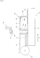
- tape feeder 23 is provided with tape feeding device 31 that draws out component supply tape 24 from reel 25 and pitch feeds it.
- Tape feeding device 31 is configured including: sprocket 32 that rotates to pitch feed with teeth engaged with feeding holes formed at equal pitches on one edge of tape feeder 23; motor 33 that serves as a drive source; and gear mechanism 34 that transmits the rotational force of motor 33 to sprocket 32 so as to rotate sprocket 32.
- motor 33 for motor 33, a motor, for example, a stepping motor, a servo motor, or the like, capable of controlling the rotation angle (rotation position) is used to perform the pitch feeding operation of component supply tape 24.
- tape feeder 23 Provided on the back end surface of tape feeder 23 are two positioning pins 35 for determining the mounting position with respect to component mounter 10, and connector 37 for both communication and power supply, which is connected to connector 36 (see fig. 3 ) on the component mounter 10 side.
- Power is supplied from component mounter 10 to tape feeder 23 by connecting connectors 36 and 37, and control section 41 (motor control section) of tape feeder 23 and control device 40 of component mounter 10 are connected so as to be able to communicate with each other.
- Control section 41 of tape feeder 23 controls the operation of motor 33 of tape feeding device 31 based on a pitch feed command transmitted from control device 40 of component mounter 10 to control the pitch feeding operation of component supply tape 24.
- tape feeder 23 is provided with sensor 42 (tape remaining amount data acquiring section) for detecting the tape remaining amount of reel 25.
- Sensor 42 is configured using, for example, an ultrasonic sensor, an optical sensor, or the like, and detects the winding diameter of component supply tape 24 of reel 25 as the tape remaining amount information, and outputs the detected information to control section 41 of tape feeder 23.
- Control section 41 of tape feeder 23 functions as a motor control section for changing an operation parameter of motor 33 of tape feeder 31 based on the tape remaining amount information detected by sensor 42.
- control section 41 of tape feeder 23 changes the operation parameter of tape feeder 33 so as to continuously or in steps decrease the torque of motor 33 as the tape remaining amount of reel 25 decreases and the load of motor 33 decreases, based on the tape remaining amount information detected by sensor 42.
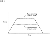
- the operation parameter of motor 33 to be changed based on the tape remaining amount information is, for example, the speed profile of the pitch feeding operation (see fig. 4 ), and the maximum speed of the speed profile is continuously or in steps decreased as the tape remaining amount of reel 25 decreases.
- the torque of motor 33 and thus the power consumption can be controlled to be continuously or in steps reduced, and the power consumption of motor 33 can be reduced without impairing the stability of the tape feeding operation, thus achieving both goals of motor 33 energy saving and stable tape feeding operation.
- operation parameter of motor 33 to be changed based on the tape remaining amount information is not limited to the speed profile of the pitch feeding operation, and for example, considering that the drive current of motor 33 and the torque are proportional to each other, control section 41 of tape feeder 23 may be configured to control the drive current of motor 33 to be continuously or in steps reduced as the tape remaining amount of reel 25 decreases. In this case too, as the tape remaining amount of reel 25 decreases, the torque of motor 33, and thus the consumed power, can be controlled so as to be continuously or in steps reduced, thus achieving both goals of motor 33 energy saving and stable tape feeding operation.
- Tape feeder 23 of the second embodiment is provided with auxiliary actuator 50 for reinforcing the drive power of the pitch feeding operation of component supply tape 24 by tape feeding device 31.
- Auxiliary actuator 50 is provided to transmit a rotational force in the pitch feeding direction to reel 25 in synchronization with the pitch feeding operation of component supply tape 24 by tape feeding device 31.
- auxiliary actuator 50 is configured from, for example, an outer rotor type motor, and the outer peripheral surface of the auxiliary actuator 50a contacts the outer peripheral edge of reel 25 so as to apply a rotational force in the pitch feeding direction to reel 25.
- a high friction elastic member such as rubber having a relatively large friction coefficient may be provided on the outer peripheral surface of rotor 50a, and the high friction elastic member may contact the outer peripheral edge of reel 25 to prevent slippage between rotor 50a and reel 25.
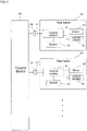
- control section 41 of tape feeder 23 functions as a motor control section for controlling the operation of motor 33 of tape feeding device 31, and also functions as an auxiliary actuator control section for changing the operation parameter of auxiliary actuator 50 based on the tape remaining amount information detected by sensor 42.
- control section 41 of tape feeder 23 changes the operation parameter of the auxiliary actuator 50 so as to continuously or in steps decrease the output of auxiliary actuator 50 as the tape remaining amount of reel 25 decreases and the load of motor 33 decreases, based on the tape remaining amount information detected by sensor 42.
- the operation parameter of auxiliary actuator 50 to be changed based on the tape remaining amount information is, for example, a speed profile, a drive current, or the like.
- tape feeder 23 of the second embodiment is provided with auxiliary actuator 50 for reinforcing the drive power to pitch feeding operation of the component supply tape by tape feeding device 31, it is sufficient to use a motor whose torque is smaller by an amount corresponding to the output the auxiliary actuator 50 as motor 33 of tape feeding device 31.
- a motor whose torque is smaller by an amount corresponding to the output the auxiliary actuator 50 as motor 33 of tape feeding device 31.
- auxiliary actuator 50 the configuration to rotate reel 25 by auxiliary actuator 50 may be changed as appropriate, and for example, the rotational force of the auxiliary actuator may be transmitted to reel 25 via a rotational transmission mechanism such as a gear mechanism or a belt transmission mechanism.
- a device for applying a tensile force to component supply tape 24 drawn out from reel 25 may be driven by an auxiliary actuator, in other words, an auxiliary actuator for reinforcing the drive power of the pitch feeding operation of component supply tape 24 by tape feeding device 31 may be provided.
- the configuration is such that sensor 42 for detecting the tape remaining amount of reel 25 is provided as the tape remaining amount information acquiring section, but sensor 42 may be omitted, and control section 41 of tape feeder 23 may function as the tape remaining amount information acquiring section, and may calculate the rotation amount of motor 33 or the feeding amount of component supply tape 24 from the first pitch feeding operation of component supply tape 24, and function as the tape feeding information acquiring section that uses the calculated value as the tape feeding information, with control section 41 of tape feeder 23 calculating the tape remaining amount information based on the tape feeding information.
- control device 40 of component mounter 10 may manage a component remaining quantity of tape feeder 23 by counting components picked up by suction nozzle 26 from tape feeder 23, and control device 41 (tape remaining amount information acquiring section) of tape feeder 23 may acquire the component remaining quantity of tape feeder 23 from control device 40 of component mounter 10 as the tape remaining amount information.
Description
- The present specification discloses technology relating to a control system of a tape feeder for drawing a component supply tape from a reel on which a component supply tape is wound and pitch feeding the component supply tape to a component pickup position.
- Generally, a tape feeder includes a reel on which a component supply tape, in which components are packaged by being arranged at a predetermined pitch, is wound, and a tape feeding device that draws out the component supply tape from the reel and feeds the leading component of the component supply tape to a component pickup position where the leading component is picked up by a suction nozzle of the component mounter.
- Further, in a tape feeder described in patent literature 1 (
JP-A-2003-124688 - Patent Literature 2 provides a further control system of a tape feeder according to the prior art.
-
- Patent Literature 1:
JP-A-2003-124688 - Patent Literature 2:
WO 2016170644 A1 - The force (load of motor) required for a tape feeding device to draw the component supply tape from the reel decreases as the remaining quantity of tape on the reel (component remaining quantity) decreases. Therefore, as the motor of the tape feeding device, a motor is used that generates the torque required to stably pitch feed the component supply tape even when the tape remaining quantity of the reel is large and the load is large.
- However, with this configuration, even when the remaining amount of tape of the reel is small and the load of the motor is decreased, the motor is operated under the same conditions as when the remaining amount of tape of the reel was large, meaning that the reel is operated with a torque larger than required, as the remaining amount of tape of the reel is small, thereby wastefully consuming power.
- Regarding this point, if a motor with a small torque margin above what is required is used to reduce power consumption, depending on the type of component supply tape used, the tape feeding rate may become slow due to insufficient torque of the motor when the remaining tape level of the reel is large, or the motor may become out of step such that the component supply tape cannot be stably fed.
- With the above-mentioned patent literature 1, there is a function for changing the rotation velocity and the rotation amount (pitch-feed amount) of the motor in accordance with the type (type of component) of the component supply tape to be used, but there is no function of optimizing the control of the motor in accordance with the remaining amount of tape on the reel.
- The invention is defined by the features of claim 1. To solve the above problems, disclosed herein is a control system of a tape feeder that includes a reel on which is wound component supply tape in which components are packaged by being arranged in a line, and a tape feeding device configured to draw out the component supply tape from the reel and pitch feed the component supply tape such that a leading component in the component supply tape is moved to a component pickup position to be picked up by a suction nozzle of a component mounter, the control system including: a tape remaining amount information acquiring section configured to acquire tape remaining amount information that is information relating to a remaining amount of the tape on the reel; an auxiliary actuator configured to reinforce drive power to pitch feeding operation of the component supply tape by the tape feeding device and a control section configured to change an operation parameter of the auxiliary actuator and a motor that is a drive source of the tape feeding device based on the tape remaining amount information acquired by the tape remaining amount information acquiring section.
- With this configuration, based on tape remaining amount information acquired by the tape remaining amount acquiring section, for example, it is possible to perform control to change, as an operation parameter of the motor or the auxiliary actuator (for example, a speed profile or a drive current of a pitch feeding operation), a torque of the motor or the auxiliary actuator so as to decrease continuously or in steps in accordance with a decrease in the load on the motor as the tape remaining amount on the reel decreases, enabling a reduction in the power consumption of the motor without losing stability in tape feeding operation, thus achieving both goals of motor energy saving and stable tape feeding operation.
- Furthermore, with this configuration, since the auxiliary actuator for reinforcing the drive power to pitch feeding operation of the component supply tape by the tape feeding device is provided, it is sufficient to use a motor whose torque is smaller by an amount corresponding to the output of the auxiliary actuator as the motor of the tape feeding device. As a result, as well as reinforcing the insufficient drive power required for the pitch feeding operation of the component supply tape by the output of the auxiliary actuator, based on the tape remaining amount information acquired by the tape remaining amount information acquiring section, for example, it is possible to perform control to change, as an operation parameter of the motor, an output of the auxiliary actuator so as to decrease continuously or in steps in accordance with a decrease in the tape remaining amount on the reel, thus achieving both goals of motor energy saving and stable tape feeding operation.
- Further embodiments are defined in the dependent claims.
-
-
Fig. 1 is a side view showing the configuration of a component mounter according to a first embodiment. -
Fig. 2 is a side view showing the configuration of the tape feeder of the first embodiment. -
Fig. 3 is a block diagram showing a configuration of a control system of the tape feeder according to the first embodiment. -
Fig. 4 shows an example of changing a speed profile of the pitch feeding operation in accordance with the tape remaining amount of the reel. -
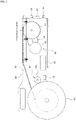
Fig. 5 is a side view showing the configuration of a tape feeder according to a second embodiment. -
Fig. 6 is a block diagram showing the configuration of the control system of the tape feeder according to the second embodiment. - A first and a second embodiment are described below.
- A first embodiment will be described with reference to
figs. 1 to 4 . - First, the configuration of
component mounter 10 will be described with reference tofig. 1 . - At least one
component mounter 10 is installed in a component mounting line for producing a component-mounted board.Conveyor 13 that conveyscircuit board 12 is provided onbase 11 of component mounter 10 (below, the conveyance direction ofcircuit board 12 byconveyor 13 is referred to as the X direction, and the direction perpendicular to that is referred to as the Y direction). Ofsupport members conveyor rails conveyor belts conveyor 13,support member 15a is fixed at a specified position, with thesupport member 15b on the opposite side being adjusted in the Y direction alongguide rail 16 by a screw mechanism (not shown) or the like such that the width of conveyor 13 (the gap betweenconveyor rails circuit board 12. - Also, feeder setting table 22 is provided to the side of
conveyor 13 onbase 11, withmultiple tape feeders 23 being removably set on feeder setting table 22 in the Y direction. Set on eachtape feeder 23 is component supply tape 24 (seefig. 2 ) on which is wound component supply tape housing many components at a fixed pitch, with thecomponent supply tape 24 being set such that the leading component of the component supply tape pulled from thecomponent supply tape 24 is positioned at a component pickup position (position at which the component is picked up by suction nozzle 26).Component mounter 10 is provided withhead moving device 28 for movingmounting head 27 that holdssuction nozzle 26 in the following order: component pickup position --> component imaging position --> component mounting position, and during component pickup operation and component mounting operation,suction nozzle 26 is raised and lowered. - As shown in
fig. 2 ,tape feeder 23 is provided withtape feeding device 31 that draws outcomponent supply tape 24 fromreel 25 and pitch feeds it.Tape feeding device 31 is configured including:sprocket 32 that rotates to pitch feed with teeth engaged with feeding holes formed at equal pitches on one edge oftape feeder 23;motor 33 that serves as a drive source; andgear mechanism 34 that transmits the rotational force ofmotor 33 to sprocket 32 so as to rotatesprocket 32. Formotor 33, a motor, for example, a stepping motor, a servo motor, or the like, capable of controlling the rotation angle (rotation position) is used to perform the pitch feeding operation ofcomponent supply tape 24. - Provided on the back end surface of
tape feeder 23 are twopositioning pins 35 for determining the mounting position with respect tocomponent mounter 10, andconnector 37 for both communication and power supply, which is connected to connector 36 (seefig. 3 ) on thecomponent mounter 10 side. Power is supplied fromcomponent mounter 10 totape feeder 23 by connectingconnectors tape feeder 23 andcontrol device 40 ofcomponent mounter 10 are connected so as to be able to communicate with each other.Control section 41 oftape feeder 23 controls the operation ofmotor 33 oftape feeding device 31 based on a pitch feed command transmitted fromcontrol device 40 ofcomponent mounter 10 to control the pitch feeding operation ofcomponent supply tape 24. - Further,
tape feeder 23 is provided with sensor 42 (tape remaining amount data acquiring section) for detecting the tape remaining amount ofreel 25.Sensor 42 is configured using, for example, an ultrasonic sensor, an optical sensor, or the like, and detects the winding diameter ofcomponent supply tape 24 ofreel 25 as the tape remaining amount information, and outputs the detected information tocontrol section 41 oftape feeder 23. -
Control section 41 oftape feeder 23 functions as a motor control section for changing an operation parameter ofmotor 33 oftape feeder 31 based on the tape remaining amount information detected bysensor 42. In the first embodiment,control section 41 oftape feeder 23 changes the operation parameter oftape feeder 33 so as to continuously or in steps decrease the torque ofmotor 33 as the tape remaining amount ofreel 25 decreases and the load ofmotor 33 decreases, based on the tape remaining amount information detected bysensor 42. Here, the operation parameter ofmotor 33 to be changed based on the tape remaining amount information is, for example, the speed profile of the pitch feeding operation (seefig. 4 ), and the maximum speed of the speed profile is continuously or in steps decreased as the tape remaining amount ofreel 25 decreases. - Accordingly, as the tape remaining amount of
reel 25 decreases and the load ofmotor 33 decreases, the torque ofmotor 33 and thus the power consumption can be controlled to be continuously or in steps reduced, and the power consumption ofmotor 33 can be reduced without impairing the stability of the tape feeding operation, thus achieving both goals ofmotor 33 energy saving and stable tape feeding operation. - Note that, operation parameter of
motor 33 to be changed based on the tape remaining amount information is not limited to the speed profile of the pitch feeding operation, and for example, considering that the drive current ofmotor 33 and the torque are proportional to each other,control section 41 oftape feeder 23 may be configured to control the drive current ofmotor 33 to be continuously or in steps reduced as the tape remaining amount ofreel 25 decreases. In this case too, as the tape remaining amount ofreel 25 decreases, the torque ofmotor 33, and thus the consumed power, can be controlled so as to be continuously or in steps reduced, thus achieving both goals ofmotor 33 energy saving and stable tape feeding operation. - Next, a second embodiment will be described with reference to
figs. 5 and6 . However, for sections which are practically the same as the first embodiment, explanations are omitted or abbreviated, with descriptions largely given for sections which are different. -
Tape feeder 23 of the second embodiment is provided withauxiliary actuator 50 for reinforcing the drive power of the pitch feeding operation ofcomponent supply tape 24 bytape feeding device 31.Auxiliary actuator 50 is provided to transmit a rotational force in the pitch feeding direction to reel 25 in synchronization with the pitch feeding operation ofcomponent supply tape 24 bytape feeding device 31. - In the second embodiment,
auxiliary actuator 50 is configured from, for example, an outer rotor type motor, and the outer peripheral surface of theauxiliary actuator 50a contacts the outer peripheral edge ofreel 25 so as to apply a rotational force in the pitch feeding direction to reel 25. Note that, a high friction elastic member such as rubber having a relatively large friction coefficient may be provided on the outer peripheral surface ofrotor 50a, and the high friction elastic member may contact the outer peripheral edge ofreel 25 to prevent slippage betweenrotor 50a andreel 25. - In this case,
control section 41 oftape feeder 23 functions as a motor control section for controlling the operation ofmotor 33 oftape feeding device 31, and also functions as an auxiliary actuator control section for changing the operation parameter ofauxiliary actuator 50 based on the tape remaining amount information detected bysensor 42. - In the second embodiment,
control section 41 oftape feeder 23 changes the operation parameter of theauxiliary actuator 50 so as to continuously or in steps decrease the output ofauxiliary actuator 50 as the tape remaining amount ofreel 25 decreases and the load ofmotor 33 decreases, based on the tape remaining amount information detected bysensor 42. In this case, the operation parameter ofauxiliary actuator 50 to be changed based on the tape remaining amount information is, for example, a speed profile, a drive current, or the like. - Since
tape feeder 23 of the second embodiment is provided withauxiliary actuator 50 for reinforcing the drive power to pitch feeding operation of the component supply tape bytape feeding device 31, it is sufficient to use a motor whose torque is smaller by an amount corresponding to the output theauxiliary actuator 50 asmotor 33 oftape feeding device 31. As a result, as well as reinforcing the insufficient drive power required for the pitch feeding operation ofcomponent supply tape 24 by the output of theauxiliary actuator 50, based on the tape remaining amount information acquired bysensor 42, for example, it is possible to perform control to change, as an operation parameter ofauxiliary actuator 50, an output ofauxiliary actuator 50 so as to decrease continuously or in steps in accordance with a decrease in the tape remaining amount onreel 25. This makes it possible to achieve both power saving and stable tape feeding operation. - Note that, the configuration to rotate
reel 25 byauxiliary actuator 50 may be changed as appropriate, and for example, the rotational force of the auxiliary actuator may be transmitted to reel 25 via a rotational transmission mechanism such as a gear mechanism or a belt transmission mechanism. Alternatively, a device (a roller, a sprocket, or the like) for applying a tensile force tocomponent supply tape 24 drawn out fromreel 25 may be driven by an auxiliary actuator, in other words, an auxiliary actuator for reinforcing the drive power of the pitch feeding operation ofcomponent supply tape 24 bytape feeding device 31 may be provided. - In the first and second embodiments above, the configuration is such that
sensor 42 for detecting the tape remaining amount ofreel 25 is provided as the tape remaining amount information acquiring section, butsensor 42 may be omitted, andcontrol section 41 oftape feeder 23 may function as the tape remaining amount information acquiring section, and may calculate the rotation amount ofmotor 33 or the feeding amount ofcomponent supply tape 24 from the first pitch feeding operation ofcomponent supply tape 24, and function as the tape feeding information acquiring section that uses the calculated value as the tape feeding information, withcontrol section 41 oftape feeder 23 calculating the tape remaining amount information based on the tape feeding information. - Alternatively,
control device 40 ofcomponent mounter 10 may manage a component remaining quantity oftape feeder 23 by counting components picked up bysuction nozzle 26 fromtape feeder 23, and control device 41 (tape remaining amount information acquiring section) oftape feeder 23 may acquire the component remaining quantity oftape feeder 23 fromcontrol device 40 ofcomponent mounter 10 as the tape remaining amount information. - In addition, the present invention is not limited to these embodiments, and it goes without saying that the present disclosure can be implemented by various modifications within a range of the claims.
-
- 10: component mounting machine;
- 22: feeder setting table;
- 23: tape feeder;
- 24: component supply tape;
- 25: reel;
- 26: suction nozzle;
- 27: mounting head;
- 28: head moving device;
- 31: tape feeding device;
- 32: sprocket;
- 33: motor;
- 40: control device of component mounter;
- 41: control section of tape feeder (motor control section, auxiliary actuator control section);
- 42: sensor (tape remaining amount data acquiring section);
- 50: auxiliary actuator
Claims (9)
- A control system of a tape feeder (23) that includes a reel (25) on which is wound component supply tape (24) in which components are packaged by being arranged in a line, and a tape feeding device (31) configured to draw out the component supply tape (24) from the reel (25) and pitch feed the component supply tape (24) such that a leading component in the component supply tape (24) is moved to a component pickup position to be picked up by a suction nozzle (26) of a component mounter, the control system comprising:
a tape remaining amount information acquiring section (41) configured to acquire tape remaining amount information that is information relating to a remaining amount of the tape on the reel (25); characterized by:an auxiliary actuator (50) configured to reinforce drive power to pitch feeding operation of the component supply tape (24) by the tape feeding device (31);a control section (41) configured to change an operation parameter of the auxiliary actuator (50) and a motor (33) that is a drive source of the tape feeding device (31) based on the tape remaining amount information acquired by the tape remaining amount information acquiring section (41). - The control system of the tape feeder (23) according to claim 1, wherein
the control section (41) is configured to change, as the operation parameter of the motor (33), a torque of the motor (33) to be lower in accordance with the tape remaining amount of the reel (25) decreasing, based on the tape remaining amount information acquired by the tape remaining amount information acquiring section (41). - The control system of the tape feeder (23) according to claim 1 or 2, wherein
the control section (41) is configured to change, as the operation parameter of the motor (33), a speed profile of pitch feeding operation, based on the tape remaining amount information acquired by the tape remaining amount information acquiring section (41). - The tape feeder (23) control system according to claim 1 or claim 2, wherein
the control section (41) is configured to change, as the operation parameter of the motor (33), a drive current, based on the tape remaining amount information acquired by the tape remaining amount information acquiring section (41). - The control system of the tape feeder (23) according to claim 1, wherein
the auxiliary actuator (50) is configured to transmit rotation force in a pitch feeding direction to the reel (25) in synchronization with pitch feeding operation of the component supply tape (24) by the tape feeding device (31). - The control system of the tape feeder (23) according to claim 1, wherein
the control section (41) is configured to change, as an operation parameter of the auxiliary actuator (50), an output of the auxiliary actuator (50) to be lower in accordance with the tape remaining amount on the reel (25) decreasing based on the tape remaining amount information acquired by the tape remaining amount information acquiring section (41). - The control system of the tape feeder (23) according to any one of the claims 1 to 6, wherein
the tape feeder (23) is provided with, as the tape remaining amount information acquiring section (41), a sensor (42) configured to detect the tape remaining amount of the reel (25). - The control system of the tape feeder (23) according to any one of the claims 1 to 6, further comprising:a tape feeding information acquiring section (41) configured to calculate a rotation amount of the motor (33) or a feeding amount of the component supply tape (24) from a first pitch feeding operation of the component supply tape (24) and take the calculated value as tape feeding information, whereinthe tape remaining amount information acquiring section (41) is configured to calculate the tape remaining amount information based on the tape feeding information acquired by the tape feeding information acquiring section (41).
- The control system of the tape feeder (23) according to any one of the claims 1 to 6, wherein
a control device of the component mounter (40) is configured to manage a component remaining quantity of the tape feeder (23) based on a quantity of components picked up by the suction nozzle (26) from the tape feeder (23), and acquire the component remaining quantity of the tape feeder (23) from the control device of the component mounter (40) as the tape remaining amount information.
Applications Claiming Priority (1)
| Application Number | Priority Date | Filing Date | Title |
|---|---|---|---|
| PCT/JP2017/030454 WO2019038899A1 (en) | 2017-08-25 | 2017-08-25 | Control system of tape feeder |
Publications (3)
| Publication Number | Publication Date |
|---|---|
| EP3675618A1 EP3675618A1 (en) | 2020-07-01 |
| EP3675618A4 EP3675618A4 (en) | 2020-08-05 |
| EP3675618B1 true EP3675618B1 (en) | 2022-07-27 |
Family
ID=65439819
Family Applications (1)
| Application Number | Title | Priority Date | Filing Date |
|---|---|---|---|
| EP17922756.6A Active EP3675618B1 (en) | 2017-08-25 | 2017-08-25 | Control system of tape feeder |
Country Status (5)
| Country | Link |
|---|---|
| US (1) | US11516953B2 (en) |
| EP (1) | EP3675618B1 (en) |
| JP (1) | JP6974477B2 (en) |
| CN (1) | CN111034386B (en) |
| WO (1) | WO2019038899A1 (en) |
Family Cites Families (24)
| Publication number | Priority date | Publication date | Assignee | Title |
|---|---|---|---|---|
| JPS63177592A (en) * | 1987-01-19 | 1988-07-21 | 三洋電機株式会社 | Parts feeder |
| JPH03205252A (en) * | 1989-12-29 | 1991-09-06 | Canon Inc | Tape-shaped article transporting device |
| JPH08171755A (en) * | 1994-12-19 | 1996-07-02 | Hitachi Ltd | Tape running controller |
| JPH117578A (en) * | 1997-06-16 | 1999-01-12 | Sanyo Electric Co Ltd | Paper filter supply device in beverage extraction device |
| US6652706B1 (en) * | 2000-12-01 | 2003-11-25 | Delaware Capital Formation, Inc. | Tape feeder with improved cover tape disposition path and drive |
| JP2003124688A (en) | 2001-10-16 | 2003-04-25 | Matsushita Electric Ind Co Ltd | Tape feeder and feeding method |
| JP4450772B2 (en) * | 2005-06-30 | 2010-04-14 | 株式会社日立ハイテクインスツルメンツ | Electronic component mounting device |
| JP4829031B2 (en) * | 2006-08-08 | 2011-11-30 | ヤマハ発動機株式会社 | Feeder data setting device for tape feeder |
| FI120432B (en) * | 2007-02-05 | 2009-10-15 | Abb Oy | Procedure for controlling electricity consumption |
| KR101575283B1 (en) * | 2009-04-01 | 2015-12-10 | 한화테크윈 주식회사 | Variable type tape feeder |
| JP5412226B2 (en) * | 2009-10-01 | 2014-02-12 | 日東電工株式会社 | Adhesive tape pasting device |
| JP5223881B2 (en) * | 2010-04-19 | 2013-06-26 | パナソニック株式会社 | Component supply method in component mounting apparatus |
| JP5529679B2 (en) * | 2010-08-27 | 2014-06-25 | 株式会社日立ハイテクインスツルメンツ | Management method and management system for electronic component mounting apparatus |
| JP5528316B2 (en) * | 2010-12-20 | 2014-06-25 | 富士機械製造株式会社 | Component supply device, electronic component mounting machine, component supply method |
| JP5748284B2 (en) * | 2011-11-01 | 2015-07-15 | 富士機械製造株式会社 | Tape feeder |
| CN104206047B (en) * | 2012-03-22 | 2016-08-24 | 富士机械制造株式会社 | Tape feeder |
| US9547284B2 (en) * | 2013-03-15 | 2017-01-17 | John S. Youngquist | Auto-setup control process |
| JP5903669B2 (en) * | 2013-05-09 | 2016-04-13 | パナソニックIpマネジメント株式会社 | Electronic component mounting apparatus and electronic component mounting method in electronic component mounting apparatus |
| CN105474773B (en) * | 2013-08-26 | 2019-07-12 | 株式会社富士 | Element fixing apparatus |
| US9743569B2 (en) * | 2015-01-06 | 2017-08-22 | Panasonic Intellectual Property Management Co., Ltd. | Electronic component supply apparatus |
| JP6550589B2 (en) * | 2015-02-24 | 2019-07-31 | パナソニックIpマネジメント株式会社 | Component mounting method |
| WO2016170644A1 (en) * | 2015-04-23 | 2016-10-27 | 富士機械製造株式会社 | Feeder device and carrier tape feeding method for feeder device |
| DE102015120016B4 (en) * | 2015-11-18 | 2018-01-04 | Asm Assembly Systems Gmbh & Co. Kg | Detection of position and movement of a component belt in a component feeder |
| CN205491654U (en) * | 2015-12-31 | 2016-08-17 | 东莞市善易机械科技有限公司 | Automatic component inserter |
-
2017
- 2017-08-25 US US16/637,921 patent/US11516953B2/en active Active
- 2017-08-25 JP JP2019537515A patent/JP6974477B2/en active Active
- 2017-08-25 EP EP17922756.6A patent/EP3675618B1/en active Active
- 2017-08-25 CN CN201780094205.2A patent/CN111034386B/en active Active
- 2017-08-25 WO PCT/JP2017/030454 patent/WO2019038899A1/en unknown
Also Published As
| Publication number | Publication date |
|---|---|
| EP3675618A1 (en) | 2020-07-01 |
| JP6974477B2 (en) | 2021-12-01 |
| EP3675618A4 (en) | 2020-08-05 |
| CN111034386A (en) | 2020-04-17 |
| US11516953B2 (en) | 2022-11-29 |
| US20200221619A1 (en) | 2020-07-09 |
| JPWO2019038899A1 (en) | 2020-07-02 |
| CN111034386B (en) | 2021-05-11 |
| WO2019038899A1 (en) | 2019-02-28 |
Similar Documents
| Publication | Publication Date | Title |
|---|---|---|
| AU2007354690B2 (en) | Automatic welding wire feed adjuster | |
| EP1894657A2 (en) | Wire electrode supply device for wire-cut electric discharge machine | |
| EP3675618B1 (en) | Control system of tape feeder | |
| CN109561647B (en) | Component supply management system and component supply management method | |
| JP2005154061A (en) | Tape feeding device | |
| JP4731579B2 (en) | Surface mount machine | |
| JP2009302329A (en) | Tape feeder monitoring device, tape feeder, surface mounting machine, and control method of tape feeder monitoring device | |
| JP2007221940A (en) | Motor controller, and electronic apparatus provided with the motor controller | |
| JP6491324B2 (en) | Feeder device and feeder tape carrier feeding method | |
| WO2017094070A1 (en) | Power supply control device and power supply control method for component supply device | |
| JP7019861B2 (en) | How to load the tape feeder and carrier tape | |
| JP2006206277A (en) | Band transporting device | |
| JP4772108B2 (en) | Component supply apparatus and surface mounting machine including the same | |
| WO2016207952A1 (en) | Condition assessing device and condition assessing method | |
| KR101609869B1 (en) | Adjust apparatus for acf tension | |
| JP2018120920A (en) | Component loading machine | |
| JP7074942B2 (en) | How to adjust the carrier tape | |
| JP3303316B2 (en) | Electronic component supply device | |
| JP2988251B2 (en) | Electronic component supply device | |
| JP2016167566A (en) | Tape feeder | |
| JP2004217406A (en) | Paper feeder of rotary press | |
| JP4884125B2 (en) | Stepping motor control device, time recorder and computer program | |
| KR20090090934A (en) | Method for compensating motor phase of electric feeder | |
| JPH04226838A (en) | Wire electric discharge machining device |
Legal Events
| Date | Code | Title | Description |
|---|---|---|---|
| STAA | Information on the status of an ep patent application or granted ep patent |
Free format text: STATUS: THE INTERNATIONAL PUBLICATION HAS BEEN MADE |
|
| PUAI | Public reference made under article 153(3) epc to a published international application that has entered the european phase |
Free format text: ORIGINAL CODE: 0009012 |
|
| STAA | Information on the status of an ep patent application or granted ep patent |
Free format text: STATUS: REQUEST FOR EXAMINATION WAS MADE |
|
| 17P | Request for examination filed |
Effective date: 20200217 |
|
| AK | Designated contracting states |
Kind code of ref document: A1 Designated state(s): AL AT BE BG CH CY CZ DE DK EE ES FI FR GB GR HR HU IE IS IT LI LT LU LV MC MK MT NL NO PL PT RO RS SE SI SK SM TR |
|
| AX | Request for extension of the european patent |
Extension state: BA ME |
|
| A4 | Supplementary search report drawn up and despatched |
Effective date: 20200706 |
|
| RIC1 | Information provided on ipc code assigned before grant |
Ipc: H05K 13/02 20060101AFI20200630BHEP Ipc: H05K 13/08 20060101ALI20200630BHEP |
|
| DAV | Request for validation of the european patent (deleted) | ||
| DAX | Request for extension of the european patent (deleted) | ||
| GRAP | Despatch of communication of intention to grant a patent |
Free format text: ORIGINAL CODE: EPIDOSNIGR1 |
|
| STAA | Information on the status of an ep patent application or granted ep patent |
Free format text: STATUS: GRANT OF PATENT IS INTENDED |
|
| INTG | Intention to grant announced |
Effective date: 20220405 |
|
| GRAS | Grant fee paid |
Free format text: ORIGINAL CODE: EPIDOSNIGR3 |
|
| GRAA | (expected) grant |
Free format text: ORIGINAL CODE: 0009210 |
|
| STAA | Information on the status of an ep patent application or granted ep patent |
Free format text: STATUS: THE PATENT HAS BEEN GRANTED |
|
| AK | Designated contracting states |
Kind code of ref document: B1 Designated state(s): AL AT BE BG CH CY CZ DE DK EE ES FI FR GB GR HR HU IE IS IT LI LT LU LV MC MK MT NL NO PL PT RO RS SE SI SK SM TR |
|
| REG | Reference to a national code |
Ref country code: CH Ref legal event code: EP |
|
| REG | Reference to a national code |
Ref country code: DE Ref legal event code: R096 Ref document number: 602017060056 Country of ref document: DE |
|
| REG | Reference to a national code |
Ref country code: AT Ref legal event code: REF Ref document number: 1507991 Country of ref document: AT Kind code of ref document: T Effective date: 20220815 |
|
| REG | Reference to a national code |
Ref country code: IE Ref legal event code: FG4D |
|
| REG | Reference to a national code |
Ref country code: LT Ref legal event code: MG9D |
|
| REG | Reference to a national code |
Ref country code: NL Ref legal event code: MP Effective date: 20220727 |
|
| PG25 | Lapsed in a contracting state [announced via postgrant information from national office to epo] |
Ref country code: SE Free format text: LAPSE BECAUSE OF FAILURE TO SUBMIT A TRANSLATION OF THE DESCRIPTION OR TO PAY THE FEE WITHIN THE PRESCRIBED TIME-LIMIT Effective date: 20220727 Ref country code: RS Free format text: LAPSE BECAUSE OF FAILURE TO SUBMIT A TRANSLATION OF THE DESCRIPTION OR TO PAY THE FEE WITHIN THE PRESCRIBED TIME-LIMIT Effective date: 20220727 Ref country code: PT Free format text: LAPSE BECAUSE OF FAILURE TO SUBMIT A TRANSLATION OF THE DESCRIPTION OR TO PAY THE FEE WITHIN THE PRESCRIBED TIME-LIMIT Effective date: 20221128 Ref country code: NO Free format text: LAPSE BECAUSE OF FAILURE TO SUBMIT A TRANSLATION OF THE DESCRIPTION OR TO PAY THE FEE WITHIN THE PRESCRIBED TIME-LIMIT Effective date: 20221027 Ref country code: NL Free format text: LAPSE BECAUSE OF FAILURE TO SUBMIT A TRANSLATION OF THE DESCRIPTION OR TO PAY THE FEE WITHIN THE PRESCRIBED TIME-LIMIT Effective date: 20220727 Ref country code: LV Free format text: LAPSE BECAUSE OF FAILURE TO SUBMIT A TRANSLATION OF THE DESCRIPTION OR TO PAY THE FEE WITHIN THE PRESCRIBED TIME-LIMIT Effective date: 20220727 Ref country code: LT Free format text: LAPSE BECAUSE OF FAILURE TO SUBMIT A TRANSLATION OF THE DESCRIPTION OR TO PAY THE FEE WITHIN THE PRESCRIBED TIME-LIMIT Effective date: 20220727 Ref country code: FI Free format text: LAPSE BECAUSE OF FAILURE TO SUBMIT A TRANSLATION OF THE DESCRIPTION OR TO PAY THE FEE WITHIN THE PRESCRIBED TIME-LIMIT Effective date: 20220727 Ref country code: ES Free format text: LAPSE BECAUSE OF FAILURE TO SUBMIT A TRANSLATION OF THE DESCRIPTION OR TO PAY THE FEE WITHIN THE PRESCRIBED TIME-LIMIT Effective date: 20220727 |
|
| REG | Reference to a national code |
Ref country code: AT Ref legal event code: MK05 Ref document number: 1507991 Country of ref document: AT Kind code of ref document: T Effective date: 20220727 |
|
| PG25 | Lapsed in a contracting state [announced via postgrant information from national office to epo] |
Ref country code: PL Free format text: LAPSE BECAUSE OF FAILURE TO SUBMIT A TRANSLATION OF THE DESCRIPTION OR TO PAY THE FEE WITHIN THE PRESCRIBED TIME-LIMIT Effective date: 20220727 Ref country code: IS Free format text: LAPSE BECAUSE OF FAILURE TO SUBMIT A TRANSLATION OF THE DESCRIPTION OR TO PAY THE FEE WITHIN THE PRESCRIBED TIME-LIMIT Effective date: 20221127 Ref country code: HR Free format text: LAPSE BECAUSE OF FAILURE TO SUBMIT A TRANSLATION OF THE DESCRIPTION OR TO PAY THE FEE WITHIN THE PRESCRIBED TIME-LIMIT Effective date: 20220727 Ref country code: GR Free format text: LAPSE BECAUSE OF FAILURE TO SUBMIT A TRANSLATION OF THE DESCRIPTION OR TO PAY THE FEE WITHIN THE PRESCRIBED TIME-LIMIT Effective date: 20221028 |
|
| REG | Reference to a national code |
Ref country code: CH Ref legal event code: PL |
|
| PG25 | Lapsed in a contracting state [announced via postgrant information from national office to epo] |
Ref country code: SM Free format text: LAPSE BECAUSE OF FAILURE TO SUBMIT A TRANSLATION OF THE DESCRIPTION OR TO PAY THE FEE WITHIN THE PRESCRIBED TIME-LIMIT Effective date: 20220727 Ref country code: RO Free format text: LAPSE BECAUSE OF FAILURE TO SUBMIT A TRANSLATION OF THE DESCRIPTION OR TO PAY THE FEE WITHIN THE PRESCRIBED TIME-LIMIT Effective date: 20220727 Ref country code: MC Free format text: LAPSE BECAUSE OF FAILURE TO SUBMIT A TRANSLATION OF THE DESCRIPTION OR TO PAY THE FEE WITHIN THE PRESCRIBED TIME-LIMIT Effective date: 20220727 Ref country code: LU Free format text: LAPSE BECAUSE OF NON-PAYMENT OF DUE FEES Effective date: 20220825 Ref country code: LI Free format text: LAPSE BECAUSE OF NON-PAYMENT OF DUE FEES Effective date: 20220831 Ref country code: DK Free format text: LAPSE BECAUSE OF FAILURE TO SUBMIT A TRANSLATION OF THE DESCRIPTION OR TO PAY THE FEE WITHIN THE PRESCRIBED TIME-LIMIT Effective date: 20220727 Ref country code: CZ Free format text: LAPSE BECAUSE OF FAILURE TO SUBMIT A TRANSLATION OF THE DESCRIPTION OR TO PAY THE FEE WITHIN THE PRESCRIBED TIME-LIMIT Effective date: 20220727 Ref country code: CH Free format text: LAPSE BECAUSE OF NON-PAYMENT OF DUE FEES Effective date: 20220831 Ref country code: AT Free format text: LAPSE BECAUSE OF FAILURE TO SUBMIT A TRANSLATION OF THE DESCRIPTION OR TO PAY THE FEE WITHIN THE PRESCRIBED TIME-LIMIT Effective date: 20220727 |
|
| REG | Reference to a national code |
Ref country code: DE Ref legal event code: R097 Ref document number: 602017060056 Country of ref document: DE Ref country code: BE Ref legal event code: MM Effective date: 20220831 |
|
| PG25 | Lapsed in a contracting state [announced via postgrant information from national office to epo] |
Ref country code: SK Free format text: LAPSE BECAUSE OF FAILURE TO SUBMIT A TRANSLATION OF THE DESCRIPTION OR TO PAY THE FEE WITHIN THE PRESCRIBED TIME-LIMIT Effective date: 20220727 Ref country code: EE Free format text: LAPSE BECAUSE OF FAILURE TO SUBMIT A TRANSLATION OF THE DESCRIPTION OR TO PAY THE FEE WITHIN THE PRESCRIBED TIME-LIMIT Effective date: 20220727 |
|
| PLBE | No opposition filed within time limit |
Free format text: ORIGINAL CODE: 0009261 |
|
| STAA | Information on the status of an ep patent application or granted ep patent |
Free format text: STATUS: NO OPPOSITION FILED WITHIN TIME LIMIT |
|
| P01 | Opt-out of the competence of the unified patent court (upc) registered |
Effective date: 20230328 |
|
| GBPC | Gb: european patent ceased through non-payment of renewal fee |
Effective date: 20221027 |
|
| PG25 | Lapsed in a contracting state [announced via postgrant information from national office to epo] |
Ref country code: AL Free format text: LAPSE BECAUSE OF FAILURE TO SUBMIT A TRANSLATION OF THE DESCRIPTION OR TO PAY THE FEE WITHIN THE PRESCRIBED TIME-LIMIT Effective date: 20220727 |
|
| 26N | No opposition filed |
Effective date: 20230502 |
|
| PG25 | Lapsed in a contracting state [announced via postgrant information from national office to epo] |
Ref country code: IE Free format text: LAPSE BECAUSE OF NON-PAYMENT OF DUE FEES Effective date: 20220825 Ref country code: FR Free format text: LAPSE BECAUSE OF NON-PAYMENT OF DUE FEES Effective date: 20220927 |
|
| PG25 | Lapsed in a contracting state [announced via postgrant information from national office to epo] |
Ref country code: SI Free format text: LAPSE BECAUSE OF FAILURE TO SUBMIT A TRANSLATION OF THE DESCRIPTION OR TO PAY THE FEE WITHIN THE PRESCRIBED TIME-LIMIT Effective date: 20220727 |
|
| PG25 | Lapsed in a contracting state [announced via postgrant information from national office to epo] |
Ref country code: BE Free format text: LAPSE BECAUSE OF NON-PAYMENT OF DUE FEES Effective date: 20220831 |
|
| PG25 | Lapsed in a contracting state [announced via postgrant information from national office to epo] |
Ref country code: GB Free format text: LAPSE BECAUSE OF NON-PAYMENT OF DUE FEES Effective date: 20221027 |
|
| PGFP | Annual fee paid to national office [announced via postgrant information from national office to epo] |
Ref country code: DE Payment date: 20230627 Year of fee payment: 7 |