EP3674623A1 - In eine raumdecke eingebettete klimaanlage - Google Patents
In eine raumdecke eingebettete klimaanlage Download PDFInfo
- Publication number
- EP3674623A1 EP3674623A1 EP17922383.9A EP17922383A EP3674623A1 EP 3674623 A1 EP3674623 A1 EP 3674623A1 EP 17922383 A EP17922383 A EP 17922383A EP 3674623 A1 EP3674623 A1 EP 3674623A1
- Authority
- EP
- European Patent Office
- Prior art keywords
- locking element
- suction grille
- decorative panel
- plate spring
- spring
- Prior art date
- Legal status (The legal status is an assumption and is not a legal conclusion. Google has not performed a legal analysis and makes no representation as to the accuracy of the status listed.)
- Granted
Links
Images


Classifications
-
- F—MECHANICAL ENGINEERING; LIGHTING; HEATING; WEAPONS; BLASTING
- F24—HEATING; RANGES; VENTILATING
- F24F—AIR-CONDITIONING; AIR-HUMIDIFICATION; VENTILATION; USE OF AIR CURRENTS FOR SCREENING
- F24F1/00—Room units for air-conditioning, e.g. separate or self-contained units or units receiving primary air from a central station
- F24F1/0007—Indoor units, e.g. fan coil units
- F24F1/0043—Indoor units, e.g. fan coil units characterised by mounting arrangements
- F24F1/0047—Indoor units, e.g. fan coil units characterised by mounting arrangements mounted in the ceiling or at the ceiling
-
- F—MECHANICAL ENGINEERING; LIGHTING; HEATING; WEAPONS; BLASTING
- F24—HEATING; RANGES; VENTILATING
- F24F—AIR-CONDITIONING; AIR-HUMIDIFICATION; VENTILATION; USE OF AIR CURRENTS FOR SCREENING
- F24F13/00—Details common to, or for air-conditioning, air-humidification, ventilation or use of air currents for screening
- F24F13/08—Air-flow control members, e.g. louvres, grilles, flaps or guide plates
- F24F13/082—Grilles, registers or guards
- F24F13/084—Grilles, registers or guards with mounting arrangements, e.g. snap fasteners for mounting to the wall or duct
-
- F—MECHANICAL ENGINEERING; LIGHTING; HEATING; WEAPONS; BLASTING
- F24—HEATING; RANGES; VENTILATING
- F24F—AIR-CONDITIONING; AIR-HUMIDIFICATION; VENTILATION; USE OF AIR CURRENTS FOR SCREENING
- F24F13/00—Details common to, or for air-conditioning, air-humidification, ventilation or use of air currents for screening
- F24F13/20—Casings or covers
-
- F—MECHANICAL ENGINEERING; LIGHTING; HEATING; WEAPONS; BLASTING
- F24—HEATING; RANGES; VENTILATING
- F24F—AIR-CONDITIONING; AIR-HUMIDIFICATION; VENTILATION; USE OF AIR CURRENTS FOR SCREENING
- F24F13/00—Details common to, or for air-conditioning, air-humidification, ventilation or use of air currents for screening
- F24F13/30—Arrangement or mounting of heat-exchangers
-
- F—MECHANICAL ENGINEERING; LIGHTING; HEATING; WEAPONS; BLASTING
- F24—HEATING; RANGES; VENTILATING
- F24F—AIR-CONDITIONING; AIR-HUMIDIFICATION; VENTILATION; USE OF AIR CURRENTS FOR SCREENING
- F24F13/00—Details common to, or for air-conditioning, air-humidification, ventilation or use of air currents for screening
- F24F13/20—Casings or covers
- F24F2013/205—Mounting a ventilator fan therein
Definitions
- the present invention relates to a ceiling concealed air-conditioning apparatus attached to a ceiling, and more particularly to a decorative panel that opens and closes a suction grille from a bottom side.
- a known conventional ceiling concealed air-conditioning apparatus includes a suction grille attached to a decorative panel so that it can be opened and detached. To avoid deterioration in design of the decorative panel, typically, a slide part is provided at an end of the suction grille and the slide part is manually moved to allow the suction grille to be engaged with the decorative panel.
- Another known example of the ceiling concealed air-conditioning apparatus incorporates a spring mechanism into a slide mechanism to save labor in opening and closing or detaching and attaching the suction grille and also integrates a locking element and a plate spring to reduce the number of components (e.g., see Patent Literature 1).
- Patent Literature 1 Japanese Unexamined Patent Application Publication No. 2009-299999
- the decorative panel is typically made of resin. Accordingly, the component integrating a slide part and a spring part is also typically made of resin. Use of such resin components may cause backlash between the components during assembly of the decorative panel due to variations in molded resin components, which are in turn due to variations in factors such as thermal stress and liquidity during molding. Also, there is a concern for durability as a stress is applied on a spring fulcrum when the spring function takes place.
- the present invention has been made in view of the above problems and aims to provide a ceiling concealed air-conditioning apparatus that can reduce backlash during assembly due to molding variations, reduce deterioration in operability due to such backlash, and improve durability by increasing the number of fulcrums for exertion of the spring function and thereby dispersing stress on the fulcrums.
- a ceiling concealed air-conditioning apparatus including: a body containing a heat exchanger and a fan and including an opening port at the bottom; a decorative panel disposed below the body, the decorative panel being configured to cover a periphery of the opening port of the body; and a suction grille including, on one edge thereof, a rotary shaft that can be attached to the decorative panel, the suction grille being configured to cover the opening port of the body so as to allow the opening port to be opened, wherein the suction grille includes: a locking element mounted on the suction grille so that it can slide and configured to be locked with the decorative panel; plate springs on respective sides of the locking element perpendicular to a sliding direction of the locking element, the plate springs extending vertically in opposite directions to each other; and spring supports provided to the suction grille and configured to support both end faces of the respective plate springs at different positions, the plate springs of the locking element include a long plate spring and a short plate spring having different length
- the ceiling concealed air-conditioning apparatus of an embodiment of the present invention includes: a body containing a heat exchanger and a fan and including an opening port at the bottom; a decorative panel disposed below the body, the decorative panel being configured to cover a periphery of the opening port of the body; and a suction grille including, on one edge thereof, a rotary shaft that can be attached to the decorative panel, the suction grille being configured to cover the opening port of the body so as to allow the opening port to be opened, wherein the suction grille includes: a locking element mounted on the suction grille and configured to be locked with the decorative panel; plate springs on respective sides of the locking element perpendicular to a sliding direction of the locking element, the plate springs extending vertically in opposite directions to each other; and spring supports provided to the suction grille and configured to support both end faces of the respective plate springs at different positions, the plate springs of the locking element include a long plate spring and a short plate spring having different lengths, and the long plate spring and the short
- Fig. 1 is a perspective view of a ceiling concealed air-conditioning apparatus according to an embodiment of the present invention when it is installed in a ceiling surface and viewed from below.
- Fig. 2 is a schematic sectional view of the inside of the body shown in Fig. 1 .
- Fig. 3 is a perspective view of the suction grille shown in Fig. 1 when it is opened.
- the body 10 of the ceiling concealed air-conditioning apparatus contains a heat exchanger 11 and a fan 12 and includes a decorative panel 13 covering a periphery of an opening port at the bottom and a suction grille 14 covering the opening port of the body 10 defined by the decorative panel 13 such that the opening port can be opened.
- the decorative panel 13 and the suction grille 14 of the ceiling concealed air-conditioning apparatus are exposed from a ceiling plate 200, and the body 10 is installed inside the ceiling plate 200.
- the body 10 of the ceiling concealed air-conditioning apparatus is connected to an outdoor unit (not shown) with refrigerant pipes.
- the heat exchanger 11 of the body 10 of the ceiling concealed air-conditioning apparatus exchanges heat between air, which is to be air-conditioned, and refrigerant.
- the heat exchanger 11 is an indoor heat exchanger forming a part of a refrigerant circuit comprised of a compressor, a four-way valve, an outdoor heat exchanger, an expansion valve, and the indoor heat exchanger successively connected to each other by pipes.
- the heat exchanger 11 serves as a condenser during a heating operation to condense and liquefy the refrigerant, and serves as an evaporator during a cooling operation to evaporate and gasify the refrigerant.
- the body 10 is formed of a cuboid metal plate with an opening port at the bottom.
- the suction grille 14 has a rectangular shape along a longitudinal direction of the body 10.
- the suction grille 14 includes, at its respective ends in a transverse direction, air inlets 16 each composed of multiple grilles and formed lengthwise.
- the suction grille 14 is formed by resin molding.
- the decorative panel 13 is fixed to the body 10.
- the decorative panel 13 is formed with an air outlet 17 on one side of the air inlets 16.
- a pivotable wind vane for changing air blow directions is attached to the air outlet 17.
- the suction grille 14 is, at its edge on one of the air inlets 16, supported by a rotary shaft 20 attached to the body 10 so as to be able to rotate.
- the suction grille 14 is capable of opening and closing the opening port of the body 10 by rotating about the rotary shaft 20.
- a pair of locking elements 30 are attached to respective edges of the suction grille 14 extending at right angles from the edge of the suction grille 14 supported by the rotary shaft 20. The locking elements 30 hold the suction grille 14 closed when the opening port of the body 10 is closed by the suction grille 14.
- the suction grille 14 is configured to open and close to enable replacement of an air filter 18 (described later) and cleaning inside the body 10.
- the air filter 18 is attached so that it can be removed, to a side of each air inlet 16 facing the inside of the body 10, which is the rear side of the air inlet 16.
- the air filter 18 collects dust contained in air entering the body 10 through each air inlet 16.
- the fan 12 includes, for example, a cross-flow fan placed on a wind path 19 communicating with the air outlet 17, and a motor (not shown) placed on one side of the cross-flow fan in the axial direction thereof.
- the heat exchanger 11 is placed in a V-shape between the fan 12 and the air inlets 16.
- driving the fan 12 causes indoor air to be suctioned from the air inlets 16 of the suction grille 14 and enter the body 10 through the air filter 18.
- the air having entered the body 10 is further suctioned by the fan 12 toward the heat exchanger 11, where the air exchanges heat with refrigerant flowing in the heat exchanger 11.
- the air having undergone the heat exchange is sent to the wind path 19 and then blown into the room from the air outlet 17.
- Fig. 4 is an enlarged view of one of the locking elements shown in Fig. 3 .
- Fig. 5 is a plan view showing the locking element of Fig. 4 when it is mounted on the suction grille.
- Fig. 6 is a plan view showing the locking element of Fig. 5 when it is supported by the suction grille so as to be able to slide.
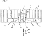
- Fig. 7 is a plan view showing the locking element of Fig. 6 when it is retracted.
- a long plate spring 31a and a short plate spring 31b each formed in a plate shape by resin molding are attached to the locking element 30.
- the long plate spring 31a and the short plate spring 31b extend at right angles in an advancing and retracting direction and are opposite to each other.
- the locking element 30 includes a locking part 32, a guide part 33, an operation part 35, a pair of slide parts in between the guide part 33, and a long hole defined by the pair of slide parts.
- the locking part 32 is a protrusion protruding upward further than a distal end of the guide part 33 of the locking element 30.
- the guide part 33 protrudes upward from the top face at each end of the locking element 30.
- the guide part 33 has an inclined surface.
- the long plate spring 31a and the short plate spring 31b extend opposite to each other and at right angles from respective ends of the locking element 30 perpendicular to its sliding direction.
- the operation part 35 extends downward from a rear part of the locking element 30.
- the slide parts receive a screw 40.
- the long hole extends lengthwise in the front-back direction of the locking element 30 and allows for insertion of the screw 40.
- the locking element 30 resides on the air inlet 15 side of the suction grille 14 and rests on a support frame extending to the inside of the air inlet 15 from the grille located at the end of the air inlet 15.
- the support frame is formed with a screw hole to receive the above-described screw 40 and supports the locking element 30 so that the locking element 30 can slide in the longitudinal direction of the long hole.
- Each of the long plate spring 31a and the short plate spring 31b extending from the respective sides of the locking element 30 is sandwiched between a main rib 15a and an auxiliary rib 15b provided on two respective grilles on the end side of the plural grilles forming the air inlet 16.
- Each of the long plate spring 31a and the short plate spring 31b is held at two points by these ribs 15a, 15b. This can correct any deformation or variation of the long and short plate springs 31a, 31b in an advancing direction 50 or a retracting direction 60 that may occur during molding of the long and short plate springs 31a, 31b.
- the main rib 15a and the auxiliary rib 15b are spring supports integrally molded with the suction grille 14 and hold both sides of each of the long plate spring 31a and the short plate spring 31b at different positions.
- the main rib 15a and the auxiliary rib 15b are positioned such that those holding the long plate spring 31a are farther from the locking part 32 than those holding the short plate spring 31b are.
- each of the long and short plate springs 31a, 31b bends in the retracting direction 60 around the main rib 15a and the auxiliary rib 15b as fulcrums against the elastic force.
- the locking element 30 is energized by the elastic force of the long and short plate springs 31a, 31b in a direction (advancing direction 50) indicated by the dashed arrow, returning to the state shown in Fig. 6 .
- the long and short plate springs 31a, 31b extending at right angles bend and thereby generate spring reaction force in the advancing direction 50 around the main rib 15a and the auxiliary rib 15b as fulcrums.
- Using the main rib 15a and the auxiliary rib 15b as fulcrums can disperse reaction force on the fulcrum parts generated by the spring reaction force.
- the spring reaction force generated in the advancing direction 50 can be adjusted by changing the distance from the locking part 32 to the main rib 15a and the auxiliary rib 15b, and enlarging this distance leads to reduced reaction force. Accordingly, the locking element 30 is mounted on the suction grille 14 such that the long plate spring 31a engages the decorative panel 13 first when the suction grille 14 is attached to the decorative panel 13. Since the spring force of the long plate spring 31a is weak, the locking part 32 does not move toward the disengaging side or slant when the engagement takes place. Thus, placing the locking element 30 such that its long plate spring 31a resides closer to the rotary shaft 20 for opening and closing of the suction grille 14 allows for stable engagement and fixing of the locking element 30 to the decorative panel 13 and smooth attachment of the suction grille 14.
- Fig. 8 is a sectional view showing a positional relationship between the locking element and the decorative panel when the suction grille of Fig. 3 is lifted close to the decorative panel.
- Fig. 9 is a sectional view showing a positional relationship between the locking element and the decorative panel when the suction grille of Fig. 8 is about to be closed into the decorative panel.
- Fig. 10 is a sectional view showing a positional relationship between the locking element and the decorative panel when the suction grille of Fig. 9 has been closed into the decorative panel.
- Fig. 11 is a sectional view showing a positional relationship between the locking element and the decorative panel when the locking element of Fig. 10 is retracted.
- the decorative panel 13 includes, on its side wall facing the locking element 30, a protrusion piece protruding horizontally toward the opening port of the body 10.
- the protrusion piece has the length equal to the width of the locking element 30 and includes at its distal end a decorative panel-side guide part 13a.
- the guide part 13a has an inclined surface parallel to the inclined surface of the suction grille-side guide part 33 of the locking element 30.
- the protrusion piece is provided inside of the design surface of the decorative panel 13. Thus, no protrusion is required to be provided on the suction grille 14, which is operated to open and close by the user, and this ensures safety.
- each of the long and short plate springs 31a, 31b on the respective sides of the locking element 30 bends in the retracting direction 60 around the main rib 15a and the auxiliary rib 15b as fulcrums against the elastic force.
- the locking element 30 advances in the direction (advancing direction 50) indicated by the dashed arrow by the elastic force of the long and short plate springs 31a, 31b, as shown in Fig. 10 , resulting in the suction grille-side locking part 32 of the locking element 30 being locked into a decorative panel-side fixed locking part 13b.
- the suction panel 14 closes the opening port of the body 10.
- the long and short plate springs 31a, 31b extending from the respective sides of the locking element 30 have different spring lengths and are also held by the main rib 15a and the auxiliary rib 15b at different distances from the locking part 32. This can, by leveraging the property that the bending spring force against the elastic force varies depending on the length of the spring, absorb any engagement displacement of the locking element 30 on the suction grille 14 in the transverse direction, improving operability.
- main rib 15a and the auxiliary rib 15b formed on the suction panel 14 as fulcrums can disperse the load applied when the plate spring exerts its spring function. This can increase the durability of the plate spring molded from a resin material. Further, arranging the main rib 15a and the auxiliary rib 15b face-to-face allows for mounting the plate spring while correcting variations in its shape, and this can absorb the backlash of the plate spring.
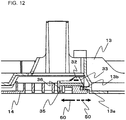
- a lower end of the operation part 35 may be protruded toward the locking part 32 to form an operation groove 36, as shown in Fig. 12.
- Fig. 12 is a sectional view showing a modification of the locking element in the present embodiment.
- the operation groove 36 can serve as a finger hook, and thus forming the operation groove 36 allows for easy hooking of fingers to move the operation part 35 in the retracting direction 60, which ensures operability.
Landscapes
- Engineering & Computer Science (AREA)
- Chemical & Material Sciences (AREA)
- Combustion & Propulsion (AREA)
- Mechanical Engineering (AREA)
- General Engineering & Computer Science (AREA)
- Air Filters, Heat-Exchange Apparatuses, And Housings Of Air-Conditioning Units (AREA)
Applications Claiming Priority (1)
| Application Number | Priority Date | Filing Date | Title |
|---|---|---|---|
| PCT/JP2017/029738 WO2019038798A1 (ja) | 2017-08-21 | 2017-08-21 | 天井埋込型空気調和機 |
Publications (3)
| Publication Number | Publication Date |
|---|---|
| EP3674623A1 true EP3674623A1 (de) | 2020-07-01 |
| EP3674623A4 EP3674623A4 (de) | 2020-08-19 |
| EP3674623B1 EP3674623B1 (de) | 2025-04-16 |
Family
ID=65439975
Family Applications (1)
| Application Number | Title | Priority Date | Filing Date |
|---|---|---|---|
| EP17922383.9A Active EP3674623B1 (de) | 2017-08-21 | 2017-08-21 | In eine raumdecke eingebettete klimaanlage |
Country Status (5)
| Country | Link |
|---|---|
| US (1) | US11614240B2 (de) |
| EP (1) | EP3674623B1 (de) |
| JP (1) | JP6758511B2 (de) |
| CN (1) | CN209326052U (de) |
| WO (1) | WO2019038798A1 (de) |
Families Citing this family (6)
| Publication number | Priority date | Publication date | Assignee | Title |
|---|---|---|---|---|
| US12442544B2 (en) * | 2019-09-27 | 2025-10-14 | Air Innovations, Llc | Ceiling mounted evaporator blower |
| US11536467B2 (en) * | 2019-09-27 | 2022-12-27 | Air Innovations, Inc. | Ceiling mounted evaporator blower with swing up hinged installation |
| KR102467323B1 (ko) * | 2020-08-07 | 2022-11-14 | 엘지전자 주식회사 | 공기청정기 |
| CN112623229B (zh) * | 2020-12-29 | 2023-03-14 | 中国航空工业集团公司西安飞机设计研究所 | 一种飞机可调节式空调供气口装置 |
| CN112944654A (zh) * | 2021-03-22 | 2021-06-11 | 珠海格力电器股份有限公司 | 一种滑动锁紧组件、面板装置及空调器 |
| JP1709599S (ja) * | 2021-03-31 | 2022-03-11 | エアーコンディショナー |
Family Cites Families (15)
| Publication number | Priority date | Publication date | Assignee | Title |
|---|---|---|---|---|
| US3724889A (en) * | 1971-10-12 | 1973-04-03 | Gen Electric | Latching device |
| US3907347A (en) * | 1974-11-21 | 1975-09-23 | Gen Motors Corp | Latch mechanism for a closure member |
| JPH04244529A (ja) * | 1991-01-10 | 1992-09-01 | Matsushita Electric Ind Co Ltd | 天井埋込形空気調和機 |
| JPH0626711U (ja) * | 1992-09-08 | 1994-04-12 | 釜屋化学工業株式会社 | コンパクト容器 |
| JPH06336871A (ja) * | 1993-05-27 | 1994-12-06 | Takigen Seizo Kk | 平面ハンドル装置 |
| US6327151B1 (en) * | 1999-10-20 | 2001-12-04 | Compal Electronics, Inc. | Locking device for locking a disk drive module inside a computer housing |
| JP2003122056A (ja) * | 2001-10-18 | 2003-04-25 | Fuji Xerox Co Ltd | 表示体 |
| JP2003262353A (ja) * | 2002-03-05 | 2003-09-19 | Mitsubishi Heavy Ind Ltd | 空気調和装置の室内ユニット及び空気調和装置の運転制御方法 |
| JP4226864B2 (ja) * | 2002-08-30 | 2009-02-18 | 東芝キヤリア株式会社 | スライド式ロック装置および空気調和装置 |
| JP4911118B2 (ja) * | 2008-05-30 | 2012-04-04 | ダイキン工業株式会社 | 空調室内機 |
| JP5216427B2 (ja) | 2008-06-13 | 2013-06-19 | 三洋電機株式会社 | 天井埋込型空気調和装置 |
| TWM366705U (en) * | 2009-04-15 | 2009-10-11 | Wistron Corp | Opening mechanism with an easy assembly structure and related electronic device |
| JP5691787B2 (ja) * | 2011-04-20 | 2015-04-01 | ダイキン工業株式会社 | 空気調和機 |
| JP6135739B2 (ja) * | 2015-10-27 | 2017-05-31 | ダイキン工業株式会社 | 空気調和機の室内ユニット |
| CN208750980U (zh) | 2016-11-30 | 2019-04-16 | 三菱电机株式会社 | 空调机的室内机 |
-
2017
- 2017-08-21 WO PCT/JP2017/029738 patent/WO2019038798A1/ja not_active Ceased
- 2017-08-21 US US16/623,901 patent/US11614240B2/en active Active
- 2017-08-21 JP JP2019537429A patent/JP6758511B2/ja active Active
- 2017-08-21 EP EP17922383.9A patent/EP3674623B1/de active Active
- 2017-08-21 CN CN201790000882.9U patent/CN209326052U/zh not_active Expired - Fee Related
Also Published As
| Publication number | Publication date |
|---|---|
| EP3674623A4 (de) | 2020-08-19 |
| US11614240B2 (en) | 2023-03-28 |
| CN209326052U (zh) | 2019-08-30 |
| EP3674623B1 (de) | 2025-04-16 |
| US20210003291A1 (en) | 2021-01-07 |
| WO2019038798A1 (ja) | 2019-02-28 |
| JP6758511B2 (ja) | 2020-09-23 |
| JPWO2019038798A1 (ja) | 2020-07-27 |
Similar Documents
| Publication | Publication Date | Title |
|---|---|---|
| EP3674623B1 (de) | In eine raumdecke eingebettete klimaanlage | |
| EP3550218B1 (de) | Klimaanlageninnenraumeinheit | |
| US8272229B2 (en) | Air conditioner and control box assembly | |
| JP5489956B2 (ja) | 空気調和機 | |
| JP4899888B2 (ja) | パネル構造 | |
| EP3346207B1 (de) | Innenraumeinheit einer klimaanlage und klimaanlage | |
| CN103946639A (zh) | 风向变更装置及具备该风向变更装置的空气调节装置 | |
| CN101629737B (zh) | 空调器室内机 | |
| CN113423996B (zh) | 室内机以及空气调节装置 | |
| CN213040644U (zh) | 空调室内机 | |
| CN206001606U (zh) | 空调机的室内机组 | |
| CN1140734C (zh) | 空调器控制盒的安装 | |
| KR101090479B1 (ko) | 공기조화기의 실내기 | |
| CN218993618U (zh) | 空调器 | |
| CN214746091U (zh) | 空调室内机 | |
| CN113167503B (zh) | 装饰面板以及室内机 | |
| CN219572240U (zh) | 一种通风面罩及整体式空调 | |
| US20230243551A1 (en) | Indoor unit for an air conditioner | |
| CN220061902U (zh) | 空调 | |
| KR20020096416A (ko) | 공기조화기의 콘트롤박스 장착구조 | |
| CN110319503A (zh) | 一种整体式机柜空调 | |
| CN203928198U (zh) | 空调机室外机 | |
| CN211261038U (zh) | 空调室内机 | |
| CN205079417U (zh) | 空调机 | |
| JP2000055453A (ja) | 空気調和機の室内ユニット据付装置 |
Legal Events
| Date | Code | Title | Description |
|---|---|---|---|
| STAA | Information on the status of an ep patent application or granted ep patent |
Free format text: STATUS: THE INTERNATIONAL PUBLICATION HAS BEEN MADE |
|
| PUAI | Public reference made under article 153(3) epc to a published international application that has entered the european phase |
Free format text: ORIGINAL CODE: 0009012 |
|
| STAA | Information on the status of an ep patent application or granted ep patent |
Free format text: STATUS: REQUEST FOR EXAMINATION WAS MADE |
|
| 17P | Request for examination filed |
Effective date: 20200224 |
|
| AK | Designated contracting states |
Kind code of ref document: A1 Designated state(s): AL AT BE BG CH CY CZ DE DK EE ES FI FR GB GR HR HU IE IS IT LI LT LU LV MC MK MT NL NO PL PT RO RS SE SI SK SM TR |
|
| AX | Request for extension of the european patent |
Extension state: BA ME |
|
| A4 | Supplementary search report drawn up and despatched |
Effective date: 20200722 |
|
| RIC1 | Information provided on ipc code assigned before grant |
Ipc: F24F 13/20 20060101AFI20200716BHEP Ipc: F24F 1/0007 20190101ALI20200716BHEP Ipc: F24F 1/0047 20190101ALI20200716BHEP Ipc: F24F 13/08 20060101ALI20200716BHEP Ipc: F24F 1/00 20190101ALI20200716BHEP Ipc: F24F 13/30 20060101ALI20200716BHEP |
|
| DAV | Request for validation of the european patent (deleted) | ||
| DAX | Request for extension of the european patent (deleted) | ||
| STAA | Information on the status of an ep patent application or granted ep patent |
Free format text: STATUS: EXAMINATION IS IN PROGRESS |
|
| 17Q | First examination report despatched |
Effective date: 20220728 |
|
| GRAP | Despatch of communication of intention to grant a patent |
Free format text: ORIGINAL CODE: EPIDOSNIGR1 |
|
| STAA | Information on the status of an ep patent application or granted ep patent |
Free format text: STATUS: GRANT OF PATENT IS INTENDED |
|
| INTG | Intention to grant announced |
Effective date: 20241213 |
|
| GRAS | Grant fee paid |
Free format text: ORIGINAL CODE: EPIDOSNIGR3 |
|
| GRAA | (expected) grant |
Free format text: ORIGINAL CODE: 0009210 |
|
| STAA | Information on the status of an ep patent application or granted ep patent |
Free format text: STATUS: THE PATENT HAS BEEN GRANTED |
|
| AK | Designated contracting states |
Kind code of ref document: B1 Designated state(s): AL AT BE BG CH CY CZ DE DK EE ES FI FR GB GR HR HU IE IS IT LI LT LU LV MC MK MT NL NO PL PT RO RS SE SI SK SM TR |
|
| REG | Reference to a national code |
Ref country code: GB Ref legal event code: FG4D |
|
| REG | Reference to a national code |
Ref country code: CH Ref legal event code: EP Ref country code: DE Ref legal event code: R096 Ref document number: 602017089002 Country of ref document: DE |
|
| REG | Reference to a national code |
Ref country code: IE Ref legal event code: FG4D |
|
| REG | Reference to a national code |
Ref country code: NL Ref legal event code: MP Effective date: 20250416 |
|
| PG25 | Lapsed in a contracting state [announced via postgrant information from national office to epo] |
Ref country code: NL Free format text: LAPSE BECAUSE OF FAILURE TO SUBMIT A TRANSLATION OF THE DESCRIPTION OR TO PAY THE FEE WITHIN THE PRESCRIBED TIME-LIMIT Effective date: 20250416 |
|
| REG | Reference to a national code |
Ref country code: AT Ref legal event code: MK05 Ref document number: 1785919 Country of ref document: AT Kind code of ref document: T Effective date: 20250416 |
|
| PG25 | Lapsed in a contracting state [announced via postgrant information from national office to epo] |
Ref country code: ES Free format text: LAPSE BECAUSE OF FAILURE TO SUBMIT A TRANSLATION OF THE DESCRIPTION OR TO PAY THE FEE WITHIN THE PRESCRIBED TIME-LIMIT Effective date: 20250416 Ref country code: FI Free format text: LAPSE BECAUSE OF FAILURE TO SUBMIT A TRANSLATION OF THE DESCRIPTION OR TO PAY THE FEE WITHIN THE PRESCRIBED TIME-LIMIT Effective date: 20250416 Ref country code: PT Free format text: LAPSE BECAUSE OF FAILURE TO SUBMIT A TRANSLATION OF THE DESCRIPTION OR TO PAY THE FEE WITHIN THE PRESCRIBED TIME-LIMIT Effective date: 20250818 |
|
| PGFP | Annual fee paid to national office [announced via postgrant information from national office to epo] |
Ref country code: DE Payment date: 20250702 Year of fee payment: 9 |
|
| REG | Reference to a national code |
Ref country code: LT Ref legal event code: MG9D |
|
| PG25 | Lapsed in a contracting state [announced via postgrant information from national office to epo] |
Ref country code: GR Free format text: LAPSE BECAUSE OF FAILURE TO SUBMIT A TRANSLATION OF THE DESCRIPTION OR TO PAY THE FEE WITHIN THE PRESCRIBED TIME-LIMIT Effective date: 20250717 Ref country code: NO Free format text: LAPSE BECAUSE OF FAILURE TO SUBMIT A TRANSLATION OF THE DESCRIPTION OR TO PAY THE FEE WITHIN THE PRESCRIBED TIME-LIMIT Effective date: 20250716 |
|
| PG25 | Lapsed in a contracting state [announced via postgrant information from national office to epo] |
Ref country code: PL Free format text: LAPSE BECAUSE OF FAILURE TO SUBMIT A TRANSLATION OF THE DESCRIPTION OR TO PAY THE FEE WITHIN THE PRESCRIBED TIME-LIMIT Effective date: 20250416 |
|
| PG25 | Lapsed in a contracting state [announced via postgrant information from national office to epo] |
Ref country code: BG Free format text: LAPSE BECAUSE OF FAILURE TO SUBMIT A TRANSLATION OF THE DESCRIPTION OR TO PAY THE FEE WITHIN THE PRESCRIBED TIME-LIMIT Effective date: 20250416 |
|
| PG25 | Lapsed in a contracting state [announced via postgrant information from national office to epo] |
Ref country code: HR Free format text: LAPSE BECAUSE OF FAILURE TO SUBMIT A TRANSLATION OF THE DESCRIPTION OR TO PAY THE FEE WITHIN THE PRESCRIBED TIME-LIMIT Effective date: 20250416 |
|
| PG25 | Lapsed in a contracting state [announced via postgrant information from national office to epo] |
Ref country code: AT Free format text: LAPSE BECAUSE OF FAILURE TO SUBMIT A TRANSLATION OF THE DESCRIPTION OR TO PAY THE FEE WITHIN THE PRESCRIBED TIME-LIMIT Effective date: 20250416 |
|
| PG25 | Lapsed in a contracting state [announced via postgrant information from national office to epo] |
Ref country code: RS Free format text: LAPSE BECAUSE OF FAILURE TO SUBMIT A TRANSLATION OF THE DESCRIPTION OR TO PAY THE FEE WITHIN THE PRESCRIBED TIME-LIMIT Effective date: 20250716 |
|
| PG25 | Lapsed in a contracting state [announced via postgrant information from national office to epo] |
Ref country code: IS Free format text: LAPSE BECAUSE OF FAILURE TO SUBMIT A TRANSLATION OF THE DESCRIPTION OR TO PAY THE FEE WITHIN THE PRESCRIBED TIME-LIMIT Effective date: 20250816 |
|
| PG25 | Lapsed in a contracting state [announced via postgrant information from national office to epo] |
Ref country code: LV Free format text: LAPSE BECAUSE OF FAILURE TO SUBMIT A TRANSLATION OF THE DESCRIPTION OR TO PAY THE FEE WITHIN THE PRESCRIBED TIME-LIMIT Effective date: 20250416 |
|
| PG25 | Lapsed in a contracting state [announced via postgrant information from national office to epo] |
Ref country code: SM Free format text: LAPSE BECAUSE OF FAILURE TO SUBMIT A TRANSLATION OF THE DESCRIPTION OR TO PAY THE FEE WITHIN THE PRESCRIBED TIME-LIMIT Effective date: 20250416 Ref country code: DK Free format text: LAPSE BECAUSE OF FAILURE TO SUBMIT A TRANSLATION OF THE DESCRIPTION OR TO PAY THE FEE WITHIN THE PRESCRIBED TIME-LIMIT Effective date: 20250416 |
|
| REG | Reference to a national code |
Ref country code: DE Ref legal event code: R097 Ref document number: 602017089002 Country of ref document: DE |
|
| PG25 | Lapsed in a contracting state [announced via postgrant information from national office to epo] |
Ref country code: CZ Free format text: LAPSE BECAUSE OF FAILURE TO SUBMIT A TRANSLATION OF THE DESCRIPTION OR TO PAY THE FEE WITHIN THE PRESCRIBED TIME-LIMIT Effective date: 20250416 |
|
| PG25 | Lapsed in a contracting state [announced via postgrant information from national office to epo] |
Ref country code: EE Free format text: LAPSE BECAUSE OF FAILURE TO SUBMIT A TRANSLATION OF THE DESCRIPTION OR TO PAY THE FEE WITHIN THE PRESCRIBED TIME-LIMIT Effective date: 20250416 |
|
| PG25 | Lapsed in a contracting state [announced via postgrant information from national office to epo] |
Ref country code: SK Free format text: LAPSE BECAUSE OF FAILURE TO SUBMIT A TRANSLATION OF THE DESCRIPTION OR TO PAY THE FEE WITHIN THE PRESCRIBED TIME-LIMIT Effective date: 20250416 Ref country code: RO Free format text: LAPSE BECAUSE OF FAILURE TO SUBMIT A TRANSLATION OF THE DESCRIPTION OR TO PAY THE FEE WITHIN THE PRESCRIBED TIME-LIMIT Effective date: 20250416 |
|
| PG25 | Lapsed in a contracting state [announced via postgrant information from national office to epo] |
Ref country code: IT Free format text: LAPSE BECAUSE OF FAILURE TO SUBMIT A TRANSLATION OF THE DESCRIPTION OR TO PAY THE FEE WITHIN THE PRESCRIBED TIME-LIMIT Effective date: 20250416 |
|
| PLBE | No opposition filed within time limit |
Free format text: ORIGINAL CODE: 0009261 |
|
| STAA | Information on the status of an ep patent application or granted ep patent |
Free format text: STATUS: NO OPPOSITION FILED WITHIN TIME LIMIT |
|
| REG | Reference to a national code |
Ref country code: CH Ref legal event code: L10 Free format text: ST27 STATUS EVENT CODE: U-0-0-L10-L00 (AS PROVIDED BY THE NATIONAL OFFICE) Effective date: 20260225 |
|
| REG | Reference to a national code |
Ref country code: CH Ref legal event code: H13 Free format text: ST27 STATUS EVENT CODE: U-0-0-H10-H13 (AS PROVIDED BY THE NATIONAL OFFICE) Effective date: 20260324 |
|
| 26N | No opposition filed |
Effective date: 20260119 |