EP3674592A1 - Anzeigevorrichtung - Google Patents
Anzeigevorrichtung Download PDFInfo
- Publication number
- EP3674592A1 EP3674592A1 EP19200527.0A EP19200527A EP3674592A1 EP 3674592 A1 EP3674592 A1 EP 3674592A1 EP 19200527 A EP19200527 A EP 19200527A EP 3674592 A1 EP3674592 A1 EP 3674592A1
- Authority
- EP
- European Patent Office
- Prior art keywords
- display
- stand
- display apparatus
- connecting member
- guide
- Prior art date
- Legal status (The legal status is an assumption and is not a legal conclusion. Google has not performed a legal analysis and makes no representation as to the accuracy of the status listed.)
- Granted
Links
- 238000010168 coupling process Methods 0.000 claims description 61
- 238000005859 coupling reaction Methods 0.000 claims description 59
- 230000008878 coupling Effects 0.000 claims description 57
- 238000003780 insertion Methods 0.000 claims description 15
- 230000037431 insertion Effects 0.000 claims description 15
- 230000007704 transition Effects 0.000 abstract 1
- 238000000034 method Methods 0.000 description 5
- 230000014509 gene expression Effects 0.000 description 4
- 238000012986 modification Methods 0.000 description 3
- 230000004048 modification Effects 0.000 description 3
- 239000000853 adhesive Substances 0.000 description 2
- 230000001070 adhesive effect Effects 0.000 description 2
- 230000000295 complement effect Effects 0.000 description 2
- 238000010586 diagram Methods 0.000 description 2
- 238000003466 welding Methods 0.000 description 2
- 238000004891 communication Methods 0.000 description 1
- 238000013461 design Methods 0.000 description 1
- 238000011161 development Methods 0.000 description 1
- 230000000694 effects Effects 0.000 description 1
- 238000005516 engineering process Methods 0.000 description 1
- 230000001788 irregular Effects 0.000 description 1
- 239000004973 liquid crystal related substance Substances 0.000 description 1
- 238000012545 processing Methods 0.000 description 1
- 230000005236 sound signal Effects 0.000 description 1
- 239000000126 substance Substances 0.000 description 1
Images


Classifications
-
- G—PHYSICS
- G09—EDUCATION; CRYPTOGRAPHY; DISPLAY; ADVERTISING; SEALS
- G09F—DISPLAYING; ADVERTISING; SIGNS; LABELS OR NAME-PLATES; SEALS
- G09F9/00—Indicating arrangements for variable information in which the information is built-up on a support by selection or combination of individual elements
-
- G—PHYSICS
- G06—COMPUTING; CALCULATING OR COUNTING
- G06F—ELECTRIC DIGITAL DATA PROCESSING
- G06F1/00—Details not covered by groups G06F3/00 - G06F13/00 and G06F21/00
- G06F1/16—Constructional details or arrangements
- G06F1/1601—Constructional details related to the housing of computer displays, e.g. of CRT monitors, of flat displays
-
- F—MECHANICAL ENGINEERING; LIGHTING; HEATING; WEAPONS; BLASTING
- F16—ENGINEERING ELEMENTS AND UNITS; GENERAL MEASURES FOR PRODUCING AND MAINTAINING EFFECTIVE FUNCTIONING OF MACHINES OR INSTALLATIONS; THERMAL INSULATION IN GENERAL
- F16M—FRAMES, CASINGS OR BEDS OF ENGINES, MACHINES OR APPARATUS, NOT SPECIFIC TO ENGINES, MACHINES OR APPARATUS PROVIDED FOR ELSEWHERE; STANDS; SUPPORTS
- F16M11/00—Stands or trestles as supports for apparatus or articles placed thereon ; Stands for scientific apparatus such as gravitational force meters
- F16M11/02—Heads
- F16M11/04—Means for attachment of apparatus; Means allowing adjustment of the apparatus relatively to the stand
- F16M11/041—Allowing quick release of the apparatus
-
- F—MECHANICAL ENGINEERING; LIGHTING; HEATING; WEAPONS; BLASTING
- F16—ENGINEERING ELEMENTS AND UNITS; GENERAL MEASURES FOR PRODUCING AND MAINTAINING EFFECTIVE FUNCTIONING OF MACHINES OR INSTALLATIONS; THERMAL INSULATION IN GENERAL
- F16M—FRAMES, CASINGS OR BEDS OF ENGINES, MACHINES OR APPARATUS, NOT SPECIFIC TO ENGINES, MACHINES OR APPARATUS PROVIDED FOR ELSEWHERE; STANDS; SUPPORTS
- F16M11/00—Stands or trestles as supports for apparatus or articles placed thereon ; Stands for scientific apparatus such as gravitational force meters
- F16M11/02—Heads
- F16M11/04—Means for attachment of apparatus; Means allowing adjustment of the apparatus relatively to the stand
- F16M11/043—Allowing translations
- F16M11/046—Allowing translations adapted to upward-downward translation movement
-
- F—MECHANICAL ENGINEERING; LIGHTING; HEATING; WEAPONS; BLASTING
- F16—ENGINEERING ELEMENTS AND UNITS; GENERAL MEASURES FOR PRODUCING AND MAINTAINING EFFECTIVE FUNCTIONING OF MACHINES OR INSTALLATIONS; THERMAL INSULATION IN GENERAL
- F16M—FRAMES, CASINGS OR BEDS OF ENGINES, MACHINES OR APPARATUS, NOT SPECIFIC TO ENGINES, MACHINES OR APPARATUS PROVIDED FOR ELSEWHERE; STANDS; SUPPORTS
- F16M11/00—Stands or trestles as supports for apparatus or articles placed thereon ; Stands for scientific apparatus such as gravitational force meters
- F16M11/02—Heads
- F16M11/04—Means for attachment of apparatus; Means allowing adjustment of the apparatus relatively to the stand
- F16M11/06—Means for attachment of apparatus; Means allowing adjustment of the apparatus relatively to the stand allowing pivoting
- F16M11/10—Means for attachment of apparatus; Means allowing adjustment of the apparatus relatively to the stand allowing pivoting around a horizontal axis
- F16M11/105—Means for attachment of apparatus; Means allowing adjustment of the apparatus relatively to the stand allowing pivoting around a horizontal axis the horizontal axis being the roll axis, e.g. for creating a landscape-portrait rotation
-
- F—MECHANICAL ENGINEERING; LIGHTING; HEATING; WEAPONS; BLASTING
- F16—ENGINEERING ELEMENTS AND UNITS; GENERAL MEASURES FOR PRODUCING AND MAINTAINING EFFECTIVE FUNCTIONING OF MACHINES OR INSTALLATIONS; THERMAL INSULATION IN GENERAL
- F16M—FRAMES, CASINGS OR BEDS OF ENGINES, MACHINES OR APPARATUS, NOT SPECIFIC TO ENGINES, MACHINES OR APPARATUS PROVIDED FOR ELSEWHERE; STANDS; SUPPORTS
- F16M11/00—Stands or trestles as supports for apparatus or articles placed thereon ; Stands for scientific apparatus such as gravitational force meters
- F16M11/02—Heads
- F16M11/18—Heads with mechanism for moving the apparatus relatively to the stand
-
- F—MECHANICAL ENGINEERING; LIGHTING; HEATING; WEAPONS; BLASTING
- F16—ENGINEERING ELEMENTS AND UNITS; GENERAL MEASURES FOR PRODUCING AND MAINTAINING EFFECTIVE FUNCTIONING OF MACHINES OR INSTALLATIONS; THERMAL INSULATION IN GENERAL
- F16M—FRAMES, CASINGS OR BEDS OF ENGINES, MACHINES OR APPARATUS, NOT SPECIFIC TO ENGINES, MACHINES OR APPARATUS PROVIDED FOR ELSEWHERE; STANDS; SUPPORTS
- F16M13/00—Other supports for positioning apparatus or articles; Means for steadying hand-held apparatus or articles
- F16M13/02—Other supports for positioning apparatus or articles; Means for steadying hand-held apparatus or articles for supporting on, or attaching to, an object, e.g. tree, gate, window-frame, cycle
- F16M13/022—Other supports for positioning apparatus or articles; Means for steadying hand-held apparatus or articles for supporting on, or attaching to, an object, e.g. tree, gate, window-frame, cycle repositionable
-
- G—PHYSICS
- G09—EDUCATION; CRYPTOGRAPHY; DISPLAY; ADVERTISING; SEALS
- G09F—DISPLAYING; ADVERTISING; SIGNS; LABELS OR NAME-PLATES; SEALS
- G09F9/00—Indicating arrangements for variable information in which the information is built-up on a support by selection or combination of individual elements
- G09F9/30—Indicating arrangements for variable information in which the information is built-up on a support by selection or combination of individual elements in which the desired character or characters are formed by combining individual elements
- G09F9/35—Indicating arrangements for variable information in which the information is built-up on a support by selection or combination of individual elements in which the desired character or characters are formed by combining individual elements being liquid crystals
-
- H—ELECTRICITY
- H04—ELECTRIC COMMUNICATION TECHNIQUE
- H04M—TELEPHONIC COMMUNICATION
- H04M1/00—Substation equipment, e.g. for use by subscribers
- H04M1/02—Constructional features of telephone sets
- H04M1/0202—Portable telephone sets, e.g. cordless phones, mobile phones or bar type handsets
- H04M1/0206—Portable telephones comprising a plurality of mechanically joined movable body parts, e.g. hinged housings
- H04M1/0208—Portable telephones comprising a plurality of mechanically joined movable body parts, e.g. hinged housings characterized by the relative motions of the body parts
- H04M1/0225—Rotatable telephones, i.e. the body parts pivoting to an open position around an axis perpendicular to the plane they define in closed position
- H04M1/0227—Rotatable in one plane, i.e. using a one degree of freedom hinge
-
- H—ELECTRICITY
- H04—ELECTRIC COMMUNICATION TECHNIQUE
- H04M—TELEPHONIC COMMUNICATION
- H04M1/00—Substation equipment, e.g. for use by subscribers
- H04M1/02—Constructional features of telephone sets
- H04M1/04—Supports for telephone transmitters or receivers
-
- H—ELECTRICITY
- H05—ELECTRIC TECHNIQUES NOT OTHERWISE PROVIDED FOR
- H05K—PRINTED CIRCUITS; CASINGS OR CONSTRUCTIONAL DETAILS OF ELECTRIC APPARATUS; MANUFACTURE OF ASSEMBLAGES OF ELECTRICAL COMPONENTS
- H05K5/00—Casings, cabinets or drawers for electric apparatus
- H05K5/0017—Casings, cabinets or drawers for electric apparatus with operator interface units
-
- H—ELECTRICITY
- H05—ELECTRIC TECHNIQUES NOT OTHERWISE PROVIDED FOR
- H05K—PRINTED CIRCUITS; CASINGS OR CONSTRUCTIONAL DETAILS OF ELECTRIC APPARATUS; MANUFACTURE OF ASSEMBLAGES OF ELECTRICAL COMPONENTS
- H05K5/00—Casings, cabinets or drawers for electric apparatus
- H05K5/02—Details
- H05K5/0217—Mechanical details of casings
- H05K5/0234—Feet; Stands; Pedestals, e.g. wheels for moving casing on floor
-
- H—ELECTRICITY
- H05—ELECTRIC TECHNIQUES NOT OTHERWISE PROVIDED FOR
- H05K—PRINTED CIRCUITS; CASINGS OR CONSTRUCTIONAL DETAILS OF ELECTRIC APPARATUS; MANUFACTURE OF ASSEMBLAGES OF ELECTRICAL COMPONENTS
- H05K5/00—Casings, cabinets or drawers for electric apparatus
- H05K5/02—Details
- H05K5/0247—Electrical details of casings, e.g. terminals, passages for cables or wiring
-
- G—PHYSICS
- G06—COMPUTING; CALCULATING OR COUNTING
- G06F—ELECTRIC DIGITAL DATA PROCESSING
- G06F2200/00—Indexing scheme relating to G06F1/04 - G06F1/32
- G06F2200/16—Indexing scheme relating to G06F1/16 - G06F1/18
- G06F2200/161—Indexing scheme relating to constructional details of the monitor
- G06F2200/1614—Image rotation following screen orientation, e.g. switching from landscape to portrait mode
-
- H—ELECTRICITY
- H04—ELECTRIC COMMUNICATION TECHNIQUE
- H04M—TELEPHONIC COMMUNICATION
- H04M1/00—Substation equipment, e.g. for use by subscribers
- H04M1/02—Constructional features of telephone sets
- H04M1/0202—Portable telephone sets, e.g. cordless phones, mobile phones or bar type handsets
- H04M1/0206—Portable telephones comprising a plurality of mechanically joined movable body parts, e.g. hinged housings
- H04M1/0208—Portable telephones comprising a plurality of mechanically joined movable body parts, e.g. hinged housings characterized by the relative motions of the body parts
- H04M1/0235—Slidable or telescopic telephones, i.e. with a relative translation movement of the body parts; Telephones using a combination of translation and other relative motions of the body parts
- H04M1/0237—Sliding mechanism with one degree of freedom
Definitions
- the disclosure relates to a display apparatus providing improved convenience in usage and utilization.
- a display apparatus is an apparatus for reproducing image contents, and may include various apparatuses such as televisions, computer monitors, smartphones, and other mobile apparatuses including tablets, etc.
- Image contents specialized for mobile apparatuses may be formatted, produced, or designed for reproduction on mobile devices typically oriented by a user in a vertical direction.
- videos and self-images selfies
- conventional display apparatuses may be formed to be long in a horizontal direction.
- the screen ratios of image contents specialized for mobile apparatuses may not be most optimally displayed on conventional display apparatuses owing to a screen ratio mismatch between mobile apparatuses and conventional display apparatuses.
- image contents intended to be displayed by conventional display apparatuses may not be most optimally displayed on mobile display apparatuses, owing to the screen ratio mismatch.
- aspects of the disclosure relate to a display apparatus providing improved convenience in usage and utilization.
- a display apparatus including a display, a stand configured to support the display, and a connecting member configured to connect a rear of the display to the stand, wherein the connecting member is configured to guide the display to move relative to the stand between: a first position in which the display obscures the stand from view of a user of the display apparatus, a second position in which the display is moved from the first position in a vertical direction relative to the stand and a lower portion of the stand is exposed to the view of the user of the display apparatus, and a third position in which the display is rotated relative to the stand.
- the display apparatus may further include a speaker arranged in the lower portion of the stand, and in the first position, the display obscures the lower portion of the stand including the speaker from the view of the user of the display apparatus, and in the second position and the third position, the display does not obscure the lower portion of the stand including the speaker is from the view of the user of the display apparatus.
- the connecting member may include a knob coupled with one surface of the connecting member
- the stand may include a guide member in which a guide slot into which the knob is inserted and moves is formed.
- the guide slot may include a first portion formed in the vertical direction to guide the display to move in the vertical direction relative to the stand, and a second portion connected to an upper end of the first portion and configured to guide the display to rotate relative to the stand.
- the knob In the first position, the knob may be located in the lower end of the first portion, and in the second position, the knob may be located between the first portion and the second portion, and in the third position, the knob may be located on a terminating end of the second portion.
- the stand may further include a pair of guide rails that are arranged in a vertical direction.
- the connecting member may include a vertical moving member coupled with the pair of guide rails and configured to move in the vertical direction, and a rotating member that is rotatively coupled with the vertical moving member, wherein, the knob is arranged on a first surface of the rotating member, and the display is coupled on a second surface of the rotating member opposing the first surface.
- the rotating member may include a rotating part inserted into a rotation hole formed on the vertical moving member and configured to rotate, and a coupling part formed integrally with the rotating part and to which the display is coupled.
- the display apparatus may further include a connecting ring arranged between the rotation hole and the rotating part and configured to connect the rotation hole and the rotating part.
- the stand may further include a driving part connected with the connecting member and configured to move the connecting member between the first position, the second position, and the third position.
- the driving part may include a motor and a driving belt connected with the motor, and arranged in parallel with the pair of guide rails.
- the vertical moving member may further include a belt insertion part arranged on one side thereof, and the driving belt may be inserted into the belt insertion part and move in a vertical direction.
- the display apparatus may further include a belt coupling part that is coupled with the belt insertion part, and wherein a coupling gear is formed.
- the driving belt may be coupled with the coupling gear, and the belt coupling part and the driving belt may move integrally.
- the stand may further include a frame member arranged along an edge of the stand and a supporting member connected with the frame member, and configured to support the connecting member in the first position.
- the second portion may be in the form of an arc equal to or smaller than 180 degrees.
- the pair of guide rails may be arranged to constitute symmetry with the guide member at the center.
- rotating part and the vertical moving member may be located on the same plane.
- the display apparatus may include a cable connecting the display and the driving board, and the rotating part may include a wiring hole formed in the center portion of the rotating part, and the cable may pass through the wiring hole.
- a component described as “on top of” or “contacts” another component should be understood to impart that a component may directly contact or be connected with the top portion of another component, but still another component may exist between the components.
- a component described as “just on top of” or “directly contacts” another component should be understood to impart that still another component does not exist between the components.
- Other expressions describing relations between components for instance, expressions such as “between ⁇ ” and “directly between ⁇ ” may be interpreted in the same manner.
- first the first
- second the second
- first component a first component
- first component a second component
- first component in a similar manner, without departing from the scope of the disclosure.
- FIGS. 1A to 2B the configuration of the display apparatus 1 according to an embodiment of the disclosure will be described with reference to FIGS. 1A to 2B .
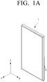
- FIG. 1A is a combined front perspective view illustrating the display apparatus 1 according to an embodiment of the disclosure.
- FIG. 1B is a combined rear perspective view illustrating the display apparatus 1 according to an embodiment of the disclosure.
- FIG. 2A is an exploded perspective view of the display apparatus 1 illustrated in FIG. 1A .
- FIG. 2B is an exploded perspective view of the display apparatus 1 illustrated in FIG. 1B .
- FIG. 2C is an exploded perspective view illustrating arrangement of a cover member 260 on a stand 200 in FIG. 1B .
- FIG. 2D is a block diagram illustrating a display 10 and a driving board 30.
- the display apparatus 1 is an apparatus that implements an image content on the display 10.
- a stand type having a support 20 supporting the display apparatus 1 is illustrated, but the display apparatus 1 may be a wall-hanging type in which the support 20 is omitted.
- the display apparatus 1 that will be explained below is an apparatus that is capable of processing an image signal received from an image source, and visually displaying the processed image.
- the display apparatus 1 may be implemented in various forms such as a television, a monitor, a portable multimedia apparatus, a portable communication apparatus, a tablet, and a smartphone, and the form of the display apparatus 1 is not limited so as long the display apparatus 1 is an apparatus that visually reproduces an image for display thereon.
- the display apparatus 1 may include a display 10, a stand 200 that that has a length L corresponding to the horizontal direction of the display 10, supports the display 10, and includes a driving board 30 that provides images to the display 10, and a connecting member 100 that is arranged between the display 10 and the stand 200 and connects the display 10 and the stand 200.
- the display 10 may process, decode, or otherwise reproduce an image signal as an image that a user can visually recognize.
- the display 10 may consist of various components including a liquid crystal display (LCD) including a backlight, or organic light emitting diodes (OLEDs) which are organic self-luminous elements, or micro light emitting diodes (LEDs) which are inorganic self-luminous elements.
- LCD liquid crystal display
- OLEDs organic light emitting diodes
- LEDs micro light emitting diodes
- a first length L of the display 10 may be formed to be longer than a second length W.
- the first length may be generally referred to as a length L of the display
- the second length W may be generally referred to as a width of the display 10.
- the first length L may be the vertical length of the display 10
- the second length may be the horizontal length of the display 10. That is, the vertical length of the display 10 illustrated in FIG. 2A may be formed to be longer than the horizontal length.
- the first length L when the display 10 is rotated to a rotated position, the first length L may be the horizontal length of the display 10, and the second length W may be the vertical length of the display 10 in the orientation of the rotated position.
- the stand 200 may be arranged on the rear side of the display 10, and support the display 10. Also, the stand 200 may have a length corresponding to the horizontal length of the display 10. Similarly, the stand 200 may have a vertical length corresponding to the vertical length of the display 10. Accordingly, the horizontal length of the stand 200 and the horizontal length of the display 10 may correspond to each other in the first position and the second position, and thus a user may have an aesthetic sense that the appearance of the display apparatus 1 is neat.
- the display 10 may cover the lower area of one surface 200a of the stand 200.
- the display 10 may cover the lower surface 200-1 of the stand 200.
- the stand 200 may have the same horizontal length and vertical length as those of the display 10.
- the stand 200 may have the same first length L and second length W as those of the display 10.
- the first length L is the vertical length
- the second length W is the horizontal length.
- the display 10 may be matched with one surface 200a of the stand 200. Accordingly, a user may have an aesthetic sense that the appearance of the display apparatus 1 is neat, through a structure in which the display 10 and the stand 200 supporting the display 10 are matched in the first position.
- the stand 200 may include a cover member 260 covering one surface 200a of the stand 200.
- the cover member 260 may be coupled with a frame member 230 and a housing 240, and protect several mechanical components and the driving board 30 arranged inside the stand 200.
- the stand 200 may include the driving board 30 providing an image to the display 10.
- the driving board 30 may receive an image signal from an image source, convert the image signal into information of an image to be displayed on the display 10, and transmit the information to the display 10 for display thereon.
- the display 10 may implement a display screen through an electronic signal transmitted from the driving board 30.
- the display 10 may be connected with the driving board 30 through a cable 40.
- the cable 40 may pass through a wiring hole S2 of a rotating part 110-1 and electrically connect the display 10 and the driving board 30.
- the display 10 may be controlled through several electronic components arranged inside the stand 200, without being limited to the driving board 30.
- the weight of the display 10 may be reduced, and thus structural stability of the display apparatus 1 may be improved.
- FIGS. 3A to 4B a detailed configuration of a connecting member 100 according to an embodiment of the disclosure will be described with reference to FIGS. 3A to 4B .
- FIG. 3A is a combined front perspective view illustrating a connecting member 100 according to an embodiment of the disclosure.
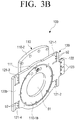
- FIG. 3B is a combined rear perspective view illustrating a connecting member 100 according to an embodiment of the disclosure.
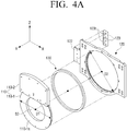
- FIG. 4A is an exploded perspective view of the connecting member 100 illustrated in FIG. 3A .
- FIG. 4B is an exploded perspective view of the connecting member 100 illustrated in FIG. 3B .
- the connecting member 100 may be coupled with each of the rear surface 10b of the display 10 and the guide rails 220 (refer to FIG. 5B ) of the stand 200, and move and rotate the display 10 with respect to the stand 200.
- the connecting member 100 may guide the display 10 to move to a first position in which the display 10 covers one surface 200a of the stand 200, as illustrated in FIG. 8A , a second position in which the display 10 moves in a vertical direction P1 to the stand 200 from the first position and the lower surface 200-1 of the stand 200 is exposed, as illustrated in FIG. 9A , and a third position in which the display 10 is rotated in a predetermined direction Q1 from the second position, as illustrated in FIG. 10A .
- the connecting member 100 may connect the display 10 and the stand 200, and at the same time, move and rotate the display 10 with respect to the stand 200.
- the connecting member 100 may include a vertical moving member 120 that is coupled with the stand 200 and move in a vertical direction to the stand 200, and a rotating member 110 that is rotatively or pivotably coupled with the vertical moving member 120 on the vertical moving member 120.
- the vertical direction may mean an up-down direction in the direction of the Z axis in FIG. 1A .
- the rotating member 110 may rotate the display 10 with respect to the stand 200, and the vertical moving member 120 may move the display 10 in a vertical direction with respect to the stand 200.
- a knob 111 may be arranged, and the other surface opposing the one surface may be coupled with the display 10.
- the knob 111 may be arranged, and the front surface 110-2a of the coupling part 110-2 of the rotating member 110 may be coupled with the display 10.
- one surface of the rotating member 110 may mean the rear surface 110-1b of the rotating part 110-1 of the rotating member 110, and the other surface of the rotating member 110 may mean the front surface 110-2a of the coupling part 110-2 of the rotating member 110.
- the rotating member 110 may include the rotating part 110-1 that is inserted into a rotation hole S1 formed on the vertical moving member 120 and rotates, and the coupling part 110-2 that is integrally formed with the rotating part 110-1 and to which the display 10 is coupled.
- the rotating part 110-1 may be formed in a circular shape, and the external diameter D1 of the rotating part 110-1 may be smaller than the diameter D2 of the rotation hole S1. Accordingly, the rotating part 110-1 may rotate along the inner circumferential surface of the rotation hole S1 formed in the center portion of the vertical moving member 120.
- the rotating part 110-1 may be inserted into the rotation hole S1 formed on the vertical moving member 120 and rotate.
- a wiring hole S2 may be formed in the center portion of the rotating part 110-1. Through the wiring hole S2, a cable 40 that connects the display 10 and the driving board 30 that is electronically connected with the display 10 and is arranged inside the stand 200 may pass.
- the display 10 may receive signals consistently and stably from the driving board 30.
- the wiring hole S2 may reduce the weight that the rotating part 110-1 occupies. Meanwhile, the wiring hole S2 may be formed such that the rotating part 110-1 has rigidity for stably rotating.
- the coupling part 110-2 may be formed integrally with the rotating part 110-1 and coupled with the display 10. Specifically, the coupling part 110-2 may be formed on one side of the rotating part 110-1. For example, the coupling part 110-2 may be formed in the upper part (the Z-axis direction) of the rotating part 110-1.
- the front surface 110-2a of the coupling part 110-2 may be coupled with the rear surface 10b of the display 10.
- the coupling part 110-2 may be screw-coupled with the display 10 through a first coupling hole b1 formed on the front surface 110-2a of the coupling part 110-2.
- the coupling method is not limited to screw-coupling, and there may be various methods of coupling the coupling part 110-2 to the display 10, such as coupling by using an adhesive, a welding method, etc.
- the front surface 110-2a of the coupling part 110-2 may be in the form corresponding to the rear surface 10b of the display 10.
- the front surface 110-2a of the coupling part 110-2 may also be formed as a flat surface.
- the front surface 110-2a of the coupling part 110-2 may also have specific curve.
- the form of the front surface 110-2a of the coupling part 110-2 may be a complementary form with the form of the rear surface 10b of the display 10.
- the coupling part 110-2 may be securely coupled with the display 10, and as the rotating member 110 rotates, the display 10 may also be rotated integrally.
- the vertical moving member 120 may be coupled with a pair of guide rails 220 (refer to FIG. 5B ) arranged on the stand 200, and slide along the pair of guide rails 220.
- the pair of guide rails 220 are arranged in a vertical direction to the stand 200, and thus the vertical moving member 120 may move in a vertical direction with respect to the stand 200.
- a plurality of guide rail coupling parts 121-1, 121-2, 121-3, 121-4 may be formed in symmetry with the rotation hole S1 formed in the center portion of the vertical moving member 120.
- the plurality of guide rail coupling parts 121-1, 121-2, 121-3, 121-4 may be formed on the rear surface 120b of the vertical moving member 120.
- each of the plurality of guide rail coupling parts 121-1, 121-2, 121-3, 121-4 may be arranged in parallel with each other.
- the first and second guide rail coupling parts 121-1, 121-2 arranged on the right side with respect to the rotation hole S1 may be arranged to be in a vertically aligned direction with each other.
- the third and fourth guide rail coupling parts 121-3, 121-4 arranged on the left side with respect to the rotation hole S1 may be arranged to be in a vertically aligned direction with each other.
- first and second guide rail coupling parts 121-1, 121-2 and the third and fourth guide rail coupling parts 121-3, 121-4 may be arranged to horizontally align with one another.
- the first guide rail coupling part 121-1 may be coupled with a first rail moving member 221-1 arranged on the first guide rail 220-1
- the second guide rail coupling part 121-2 may be coupled with a second rail moving member 221-2 arranged on the first guide rail 220-1.
- the third guide rail coupling part 121-3 may be coupled with a third rail moving member 221-3 arranged on the second guide rail 220-2, and the fourth guide rail coupling part 121-4 may be coupled with a fourth rail moving member 221-4 arranged on the second guide rail 220-2. Accordingly, the vertical moving member 120 may be coupled with a pair of guide rails 220.
- each of the plurality of guide rail coupling parts 121-1, 121-2, 121-3, 121-4 may be coupled with each of the plurality of rail moving members 221 through a second coupling hole b2 formed on each of the plurality of guide rail coupling parts 121.
- the coupling method is not limited to screw-coupling, and there may be various methods of coupling the vertical moving member 120 to the guide rails 220, such as by using an adhesive, a welding method, etc.
- the vertical moving member 120 may move in a vertical direction along a pair of guide rails 220.
- the vertical moving member 120 has a structure of being connected to the rotating member 110 connected to the display 10, as the vertical moving member 120 moves in a vertical direction along the stand 200, the display 10 may move in a vertical direction relative to the stand 200.
- the vertical moving member 120 may include a belt insertion part 122 that is arranged on one side of the vertical moving member 120 and into which the driving belt 272 is inserted.
- the one side of the vertical moving member 120 for housing the belt insertion part 122 may be the left side portion or the right side portion of the vertical moving member 120.
- the belt insertion part 122 may be formed in the left side portion or the right side portion of the vertical moving member 120 according to the location at which the driving belt 272 of the driving part 270 is arranged.
- the belt insertion part 122 may be arranged in the left side portion of the vertical moving member 120.
- the vertical moving member 120 may include a belt coupling part 123 that is coupled with the belt insertion part 122 and at which a coupling gear123t coupled with the driving belt 272 is formed.
- one surface of the driving belt 272 may be inserted into the belt accommodating groove 122b of the belt insertion part 122, and the other surface of the driving belt 272 may be coupled with the coupling gear 123t of the belt coupling part 123.
- the driving belt 272 may be inserted into a space formed by the belt insertion part 122 and the belt coupling part 123, and may be fixed to the vertical moving member 120 by the coupling gear 123t.
- the vertical moving member 120 may also move in a vertical direction. That is, considering that the vertical moving member 120 is coupled with the rotating member 110 connected to the display 10, as the vertical moving member 120 moves in a vertical direction, the display 10 may move in a vertical direction relative to the stand 200.
- the driving belt 272 may be driven in a first direction R1 (refer to FIG. 7C ) and move in a second direction R2 (refer to FIG. 7C ) opposite to the first direction, and thereby control the movement and rotation of the display 10.
- the driving belt 272 may transmit the power source of the motor 271 to the connecting member 100, and thereby provide for the movement of the display 10.
- the connecting member 100 may include a connecting ring 130 that is arranged between the rotation hole S1 and the rotating part 110-1 and connects the rotation hole S1 and the rotating part 110-1.
- the connecting ring 130 may be formed in a ring shape, and the diameter of the outer circumference thereof may be smaller than the diameter D2 of the rotation hole S1, and the diameter of the inner circumference thereof may be bigger than the external diameter D1 of the rotating part 110-1.
- the outer circumferential surface of the connecting ring 130 may contact the inner circumferential surface of the rotation hole S1 of the vertical moving member 120, and the inner circumferential surface of the connecting ring 130 may contact the outer circumferential surface of the rotating part 110-1.
- the rotating part 110-1 may be located stably inside the rotation hole S1 of the vertical moving member 120. Also, in case the rotating part 110-1 rotates inside the rotation hole S1 of the vertical moving member 120, the connecting ring 130 may adjust friction with the rotating part 110-1, and thereby adjust the rotating speed of the rotating member 110 with respect to the vertical moving member 120. That is, the connecting ring 130 may adjust the rotating speed of the display 10 with respect to the stand 200.
- the connecting ring 130 may arrange the rotating part 110-1 stably inside the rotation hole S1, and thus the rotating part 110-1 and the vertical moving member 120 may be located on the same plane.
- the connecting ring 130 may prevent the rotating member 110 from being spaced apart from the vertical moving member 120, and minimalize the coupled structure of the rotating member 110 and the vertical moving member 120 in terms of space. Accordingly, the space in which the display 10 and the stand 200 are coupled is minimized, and the display apparatus 1 may be implemented to have a slim form factor.
- the connecting ring 130 may be a bearing inserted into the rotation hole S1.
- the connecting member 100 may include a knob 111 that is coupled with one surface of the connecting member 100, and is inserted into a guide slot 211 (refer to FIG. 5B ) of the guide member 210 and moves along the guide slot 211.
- the knob 111 may be arranged on the rear surface 110-1b of the rotating part 110-1.
- the connecting member 100 may move, and as the knob 111 rotates in a specific direction, the rotating member 110 of the connecting member 100 may rotate.
- the vertical moving member 120 and the connecting member 100 including the vertical moving member 120 may move in a vertical direction.
- the rotating member 110 moves vertically together with the vertical moving member 120, but does not rotate.
- the connecting member 100 moves in a vertical direction
- the display 10 connected with the connecting member 100 may move in a vertical direction relative to the stand 200.
- the rotating member 110 may rotate in a predetermined direction.
- the rotating member 110 rotates, and the vertical moving member 120 does not rotate.
- the display 10 connected with the connecting member 100 may rotate in a predetermined direction with respect to the stand 200.
- the diameter of the knob 111 may be formed to be smaller than or the same as the width of the guide slot 211. Also, the knob 111 and the guide slot 211 are slide-coupled, and thus the knob 111 may move naturally along the guide slot 211.
- the knob 111 may adjust the movement and rotation of the connecting member 100 and the display 10 connected with the connecting member 100 in a vertical direction with respect to the stand 200.
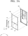
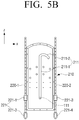
- FIG. 5A is an exploded perspective view of the stand 200 according to an embodiment of the disclosure
- FIG. 5B is a front view illustrating the guide member 210 and a pair of guide rails 220 according to an embodiment of the disclosure.
- the stand 200 may be arranged on the rear side of the display 10, and support the display 10. Also, the stand 200 may include a guide member 210 that is arranged on the stand 200 and guides the movements of the connecting member 100 and the display 10, a pair of guide rails 220 arranged in a vertical direction to the stand 200, a frame member 230 arranged along the edge of the stand 200, a housing 240 forming the exterior of the rear surface of the display apparatus 1, and a speaker 250 arranged in the lower part of the stand 200.
- a guide member 210 that is arranged on the stand 200 and guides the movements of the connecting member 100 and the display 10
- a pair of guide rails 220 arranged in a vertical direction to the stand 200
- a frame member 230 arranged along the edge of the stand 200
- a housing 240 forming the exterior of the rear surface of the display apparatus 1
- a speaker 250 arranged in the lower part of the stand 200.
- a guide slot 211 into which the knob 111 is inserted and moves may be formed.
- the guide slot 211 may be formed in the center portion of the stand 200, but the guide slot 211 may be formed on the left side or the right side of the stand.
- the guide member 210 may guide the movement and rotation of the display 10 with respect to the stand 200.
- the display 10 may move in a vertical direction or in a predetermined direction.
- the knob 111 of the connecting member 100 may be inserted, and move the connecting member 100 and the display 10.
- the guide slot 211 may include a first portion 211-1 formed in a vertical direction and a second portion 211-2 that is consecutively connected to the upper end of the first portion 211-1 and is bent in a predetermined direction that is other than the vertical direction, thereby causing rotation of the display 10.
- a predetermined direction means the direction in which the display 10 rotates with respect to the stand 200, and the direction of rotation may be a clockwise direction or a counter clockwise direction.
- the display 10 may rotate in a clockwise direction with respect to the stand 200.
- the display 10 may rotate in a counter clockwise direction with respect to the stand 200.
- the first portion 211-1 may be formed in a vertical direction. Accordingly, in a configuration in which the knob 111 moves along the first portion 211-1, the display 10 may move in a vertical direction with respect to the stand 200.
- the second portion 211-2 may be consecutively connected to the first portion 211-1, and may be bent or curved in a predetermined direction.
- the second portion 211-2 may be in the form of an arc equal to or smaller than 180 degrees. Accordingly, in case the knob 111 moves by 180 degrees along the second portion 211-2, the display 10 may rotate by 90 degrees with respect to the stand 200.
- the shape of the second portion 211-2 may include any shape that causes rotation of the display 10 when the knob 111 slides along the second portion 211-2.
- the shapes may include angles, arcs, or any combination regular or irregular shapes that induces rotation of the display 10 when the knob 111 slides along the second portion 211-2.
- one end 211-2a (refer to FIG. 10A ) of the second portion 211-2 is arranged to be bent by 90 degrees with respect to the first portion 211-1. Accordingly, in a configuration in which the knob 111 is arranged on one end 211-2a of the second portion 211-2 from the first portion 211-1, the knob 111 is ultimately rotated by 90 degrees. Thus, the display 10 may rotate by 90 degrees with respect to the stand 200.
- the curvature of the second portion 211-2 may vary depending on design, but for the stable rotating operation of the display 10, the arc constituting the second portion 211-2 may be a portion of a semicircle to provide for a smooth rotation throughout the extent of the shape of the second portion 211-2.
- the guide member 210 may rotate the connecting member 100 and the display 10 connected with the connecting member 100 in a vertical direction or a predetermined direction with respect to the stand 200 through the mechanism of the guide slot 211.
- the guide rail 220 may be arranged in a vertical direction with respect to the stand 200, and the guide rail 220 may be connected with the connecting member 100 and guide the connecting member 100 in a vertical direction.
- the guide rail 220 may include a rail moving member 221 that is slide-coupled with the guide rail 220.
- the rail moving member 221 may be coupled with the guide rail coupling part 121-1, 121-2, 121-3, 121-4 of the vertical moving member 120.
- the guide rail 220 may consist of a pair of guide rails 220-1, 220-2 arranged to constitute symmetry with the guide member 210 at the center.
- first guide rail coupling part 121-1 may be coupled with the first rail moving member 221-1 arranged on the first guide rail 220-1
- second guide rail coupling part 121-2 may be coupled with the second rail moving member 221-2 arranged on the first guide rail 220-1.
- the third guide rail coupling part 121-3 may be coupled with the third rail moving member 221-3 arranged on the second guide rail 220-2, and the fourth guide rail coupling part 121-4 may be coupled with the fourth rail moving member 221-4 arranged on the second guide rail 220-2. That is, the vertical moving member 120 may be coupled with a pair of guide rails 220.
- the vertical moving member 120 may move in a vertical direction along a pair of guide rails 220 arranged in a vertical direction.
- the vertical moving member 120 is connected with each of the pair of guide rails 220 symmetrically with the rotation hole S1 in the center.
- the vertical moving member 120 may move in a vertical direction in parallel, without being tilted in a direction of one side.
- the frame member 230 may be arranged inside the housing 240 of the stand 200, and stably support the exterior of the stand 200.
- the display apparatus 1 may not be tilted or fall in one direction.
- the frame member 230 may distribute the weight of the display 10, and thereby prevent deformation of the exterior of the stand 200 due to the weight of the display 10.
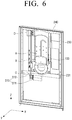
- the stand 200 may include a supporting member 231 that is connected with the frame member 230, and supports the connecting member 100 in the first position.
- the supporting member 231 is arranged to cross over the frame member 230 in a horizontal direction, and as illustrated in FIG. 6 , the supporting member 231 may contact the lower surface of the vertical moving member 120 in the first position.
- the supporting member 231 may distribute the load of the display 10 transmitted to the vertical moving member 120 by supporting the vertical moving member 120.
- the supporting member 231 may include a supporting groove 231a that is complementary with the form of the lower part of the vertical moving member 120.
- the supporting groove 231a may be formed to also have a specific curvature.
- the load of the display 10 transmitted to the vertical moving member 120 may be distributed more stably.
- the housing 240 may form the exterior of the stand 200, and protect several components arranged inside the stand 200 from external foreign substances.
- the guide member 210, a pair of guide rails 220, the driving part 270, the speaker 250, etc. arranged inside the stand 200 may be protected from the outside, and thus durability of the display apparatus 1 can be improved.
- the form of the housing 240 may be diverse, but the housing 240 may be formed such that the size of one surface 200a of the stand 200 is the same as the size of the cross section of the display 10.
- the stand 200 and the housing 240 constituting the exterior of the stand 200 may also be formed to have dimensions of the first length L and the second length W.
- the display 10 and the stand 200 form a matched exterior, and thus a user may perceive a pleasing aesthetic sense of the display apparatus 1.
- the speaker 250 is an apparatus that outputs a sound based on a sound signal included with an image signal according to a wave form that can be audibly recognized by a user. As illustrated in FIG. 2A , the speaker 250 may be arranged in the lower part of the stand 200.
- the lower part of the stand 200 may mean the area of the stand 200 that is exposed when the display 10 moves from the first position in which the display 10 covers one surface 200a of the stand 200 to the second position in which the display 10 is moved in a vertical direction relative to the stand 200.
- the speaker 250 may be arranged in the rear side of the lower surface 200-1 of the stand 200.
- the speaker 250 of the stand 200 is exposed, and thus a user may be provided with a sound of high output along with an image.
- a speaker array may be formed as omni-directional speakers are aligned, without being limited to arrangement of a single speaker.
- FIG. 6 is a combined perspective view of the connecting member 100 and the stand 200 according to an embodiment of the disclosure.
- FIG. 7A is an enlarged view illustrating the area A in FIG. 6 .
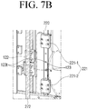
- FIG. 7B is an enlarged view illustrating the area B in FIG. 6 .
- FIG. 7C is an enlarged view illustrating the area C in FIG. 6 .
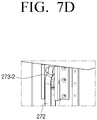
- FIG. 7D is an enlarged view illustrating the area D in FIG. 6 .
- the rotating member 110 is illustrated to be transparent, and in FIG. 7B , the connecting member 100 is illustrated to be translucent.
- the stand 200 may include a driving part 270 that is connected with the connecting member 100 and moves the connecting member 100 between the first position, the second position, and the third position.
- the driving part 270 may include a motor 271 and a driving belt 272 that is connected with the motor 271 and is arranged in parallel with a pair of guide rails 220. That is, the driving belt 272 may be arranged in a vertical relationship to the stand 200.
- a portion of the driving belt 272 may be inserted into the belt insertion part 122, and may be coupled with the coupling gear 123t.
- the vertical moving member 120 coupled with the driving belt 272 and the connecting member 100 including the vertical moving member 120 may move in parallel with the direction in which the driving belt 272 moves. Accordingly, the power provided from the motor 271 may be transmitted to the vertical moving member 120 by the driving belt 272 without dissipation.
- a first axis 273-1 connected with the motor 271 and rotates and a second axis 273-2 that rotates the driving belt 272 may be respectively arranged.
- the driving belt 272 may be connected with the first axis 273-1 and the second axis 273-2 and maintained to have specific tension, and rotate in a first direction R1 and a second direction R2 according to driving of the motor 271.
- the connecting member 100 connected with the driving belt 272 ascends in a vertical direction (the P1 direction, refer to FIG. 9A ), and as the knob 111 of the connecting member 100 moves in the second portion 211-2 of the guide slot 211, the rotating member 110 of the connecting member 100 rotates (the Q1 direction, refer to FIG. 10A ).
- the display 10 sequentially moves from the first position to the third position via the second position.
- the knob 111 of the connecting member 100 rotates in a direction opposite to one end 211-2a of the second portion 211-2 of the guide slot 211 (the Q2 direction, refer to FIG. 10A ), and the connecting member 100 descends in a vertical direction (the P2 direction, refer to FIG. 9A ).
- the display 10 sequentially moves from the third position to the first position via the second position.
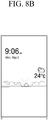
- FIG. 8A is a front view of the display apparatus 1 in which a first position is indicated according to an embodiment of the disclosure.
- FIG. 8B is a front view illustrating the screen of the display 10 in FIG. 8A .
- FIG. 9A is a front view of the display apparatus 1 in which a second position is indicated according to an embodiment of the disclosure.
- FIG. 9B is a front view illustrating the screen of the display 10 in FIG. 9A .
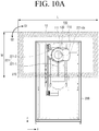
- FIG. 10A is a front view of the display apparatus 1 in which a third position is indicated according to an embodiment of the disclosure.
- FIG. 10B is a front view illustrating the screen of the display 10 in FIG. 10A .
- the display 10 may be located in the first position in which the display 10 covers one surface 200a of the stand 200.
- the display 10 obscures view of a portion of the stand 200 or all of the stand 200a from view of a user who views the display apparatus 1 from a front side of the display apparatus 1.
- the portion of the stand 200 obscured by the display 10 may include the speaker 250.
- the knob 111 may be located in the lower end 211-1a of the first portion 211-1 of the guide slot 211.
- the display 10 may display simple contents.
- the display 10 may display pictures, dates, time, weather, simple contents, etc.
- the speaker 250 may be covered by the display 10. Meanwhile, the speaker 250 may emit simple signal sounds depending on needs.
- the image displayed in the first position and the sound emitted in the first position are not limited to the descriptions above. Any image and any sound may be reproduced by the display apparatus 1 in the first position.
- the display 10 may be located in the second position in which the display 10 moved in a vertical direction relative to the stand 200, from the first position.
- the knob 111 may be located between the first portion 211-1 and the second portion 211-2 of the guide slot 211.
- the driving belt 272 connected with the first axis 273-1 rotates in the first direction R1.
- the connecting member 100 connected with the driving belt 272 ascends in a vertical direction (the P1 direction), and the display 10 is located in the second position in which the display 10 moved in a vertical direction to the stand 200.
- the motor 271 may move the knob 111 until the knob 111 is located between the first portion 211-1 and the second portion 211-2 from the lower end 211-1a of the first portion 211-1.
- the display 10 may display image contents that accompany audio contents.
- the display 10 may reproduce image contents appropriate for a vertically oriented screen in the second position.
- a vertically oriented screen may mean a display screen of which height from top to bottom is longer than the width from left to right.
- the speaker 250 may be exposed as to be unobscured by the display 10.
- exposure of the speaker 250 may mean that the emission portion of the speaker 250 from which the sound of the speaker 250 is emitted is exposed.
- an image content may be reproduced on the display 10, and at the same time, audio content included along with the image content may be emitted through the speaker 250.
- the display apparatus 1 is interlocked with a mobile apparatus of a user, e.g., a smartphone, the screen of the mobile apparatus of the user may be displayed on the display 10. Accordingly, the user may view the image content on the screen of the mobile apparatus and various types of information through the display apparatus 1, which is a screen larger than the screen of the mobile apparatus of the user, while having a similar aspect ratio to that of the screen of the mobile apparatus.
- the display apparatus 1 may automatically move from the first position to the second position.
- the display apparatus 1 may move from the first position to the second position, even if there is no separate instruction from the user.
- the user may instantly recognize that the mobile apparatus of the user and the display apparatus 1 are in an interlocked state.
- the display apparatus 1 may reproduce music contents, without being limited to image contents.
- the album jacket, lyrics, etc. of a music content are displayed, and music of high output may be reproduced through the speaker 250 exposed in the second position.
- the display 10 may be located in the third position in which the display 10 is rotated in a predetermined direction from the second position.
- the knob may be located on one end 211-2a of the second portion 211-2 of the guide slot 211, which may be a terminating end.
- the driving belt 272 connected with the first axis 273-1 rotates in the first direction R1.
- the rotating member 110 connected with the driving belt 272 through the vertical moving member 120 rotates in the Q1 direction, and the display 10 is located in the third position in which the display 10 moved in a predetermined direction Q1 with respect to the stand 200 from the second position.
- the display 10 may display image contents that accompany sounds.
- the display 10 may reproduce image contents appropriate for a horizontally oriented screen in the third position.
- a horizontally oriented screen may mean a display screen of which length from right to left is longer than the height from top to bottom.
- the display 10 may display image contents having a screen ratio of 16:9, such as movies and dramas.
- the speaker 250 may be exposed, without being obscured by the display 10.
- exposure of the speaker 250 may mean that the emission portion of the speaker 250 from which the sound of the speaker 250 is emitted is exposed.
- an image content may be reproduced on the display 10, and at the same time, audio content included with the image content may be emitted through the speaker 250.
- the display apparatus 1 may implement a display 10 in configurations of variable width and length through one structure. Accordingly, video content oriented in a vertical direction or a horizontal direction may be appropriately displayed according to aspect ratios thereof.
- a vertical-type display 10 that suits image contents appropriate for a vertical screen, and a horizontal-type display 10 that suits image contents appropriate for a horizontal screen may be implemented.
- a processor of the display apparatus 1 may detect the orientation or aspect ratio of the content from metadata of the content, and control to drive the motor to position the display in the first position or the second position corresponding to an aspect ratio of the content to be displayed in the vertical orientation and to position the display in the third position corresponding to an aspect ratio of the content to be displayed in the horizontal orientation.
Landscapes
- Engineering & Computer Science (AREA)
- General Engineering & Computer Science (AREA)
- Mechanical Engineering (AREA)
- Theoretical Computer Science (AREA)
- General Physics & Mathematics (AREA)
- Physics & Mathematics (AREA)
- Microelectronics & Electronic Packaging (AREA)
- Computer Hardware Design (AREA)
- Human Computer Interaction (AREA)
- Signal Processing (AREA)
- Chemical & Material Sciences (AREA)
- Crystallography & Structural Chemistry (AREA)
- Devices For Indicating Variable Information By Combining Individual Elements (AREA)
Applications Claiming Priority (1)
| Application Number | Priority Date | Filing Date | Title |
|---|---|---|---|
| KR1020180173872A KR102564304B1 (ko) | 2018-12-31 | 2018-12-31 | 디스플레이 장치 |
Publications (2)
| Publication Number | Publication Date |
|---|---|
| EP3674592A1 true EP3674592A1 (de) | 2020-07-01 |
| EP3674592B1 EP3674592B1 (de) | 2024-05-01 |
Family
ID=68165445
Family Applications (1)
| Application Number | Title | Priority Date | Filing Date |
|---|---|---|---|
| EP19200527.0A Active EP3674592B1 (de) | 2018-12-31 | 2019-09-30 | Anzeigevorrichtung |
Country Status (5)
| Country | Link |
|---|---|
| US (1) | US11262019B2 (de) |
| EP (1) | EP3674592B1 (de) |
| KR (1) | KR102564304B1 (de) |
| CN (1) | CN111383519B (de) |
| WO (1) | WO2020141697A1 (de) |
Families Citing this family (9)
| Publication number | Priority date | Publication date | Assignee | Title |
|---|---|---|---|---|
| EP3750752B1 (de) * | 2018-02-11 | 2024-04-03 | BYD Company Limited | Stellantrieb zur einstellung eines anzeigeendgeräts und fahrzeug |
| USD968399S1 (en) * | 2019-01-02 | 2022-11-01 | Samsung Electronics Co., Ltd. | Audio device with display |
| USD951249S1 (en) * | 2019-01-02 | 2022-05-10 | Samsung Electronics Co., Ltd. | Audio device with display |
| USD971915S1 (en) * | 2019-01-02 | 2022-12-06 | Samsung Electronics Co., Ltd. | Audio device with display |
| TWI698776B (zh) * | 2019-02-01 | 2020-07-11 | 仁寶電腦工業股份有限公司 | 具有升降式顯示器的電子裝置 |
| KR102199121B1 (ko) * | 2020-08-07 | 2021-01-06 | 엘지디스플레이 주식회사 | 디스플레이 장치 |
| KR20220018845A (ko) * | 2020-08-07 | 2022-02-15 | 엘지디스플레이 주식회사 | 디스플레이 장치 |
| KR20220018783A (ko) * | 2020-08-07 | 2022-02-15 | 삼성전자주식회사 | 디스플레이 장치 및 이의 제어 방법 |
| KR102252777B1 (ko) * | 2020-12-09 | 2021-05-14 | 엘지디스플레이 주식회사 | 디스플레이 장치 |
Citations (4)
| Publication number | Priority date | Publication date | Assignee | Title |
|---|---|---|---|---|
| EP1420327A1 (de) * | 2002-11-14 | 2004-05-19 | Hewlett-Packard Company (a Delaware corporation) | Träger |
| US20070195495A1 (en) * | 2006-02-21 | 2007-08-23 | Samsung Electronics Co., Ltd. | Stand and display apparatus having the same |
| US20140029176A1 (en) * | 2012-07-30 | 2014-01-30 | Wistron Corporation | Electronic apparatus and stand thereof |
| US20150076308A1 (en) * | 2013-09-13 | 2015-03-19 | Hon Hai Precision Industry Co., Ltd. | Bracket for supporting electronic device |
Family Cites Families (22)
| Publication number | Priority date | Publication date | Assignee | Title |
|---|---|---|---|---|
| JP3595547B2 (ja) | 2002-08-22 | 2004-12-02 | シャープ株式会社 | 薄型表示装置 |
| KR100534120B1 (ko) | 2003-08-21 | 2005-12-08 | 삼성전자주식회사 | 모니터장치 |
| KR100565686B1 (ko) | 2004-08-12 | 2006-03-30 | 엘지전자 주식회사 | 영상표시장치의 스탠드 어셈블리 |
| JP4741846B2 (ja) * | 2005-01-14 | 2011-08-10 | Necディスプレイソリューションズ株式会社 | 薄型表示装置用スタンド |
| US8139171B2 (en) * | 2005-06-24 | 2012-03-20 | Sony Corporation | Audio/display device |
| KR20070033210A (ko) | 2005-09-21 | 2007-03-26 | 삼성전자주식회사 | 디스플레이장치 |
| KR101164820B1 (ko) * | 2005-09-22 | 2012-07-12 | 삼성전자주식회사 | 디스플레이장치 |
| US8352000B2 (en) * | 2006-08-22 | 2013-01-08 | Samsung Electronics Co., Ltd. | Mobile phone having dual connection member and hinge device thereof |
| KR101300990B1 (ko) | 2007-01-02 | 2013-08-27 | 엘지전자 주식회사 | 디스플레이 기기 |
| US20080236014A1 (en) * | 2007-03-29 | 2008-10-02 | Kinpo Electronics, Inc. | Autorotative digital photo frame |
| TWI369669B (en) * | 2007-06-07 | 2012-08-01 | Lite On Technology Corp | Method for enabling a digital photo frame to automatically adjust a placement direction thereof, and digital photo frame applying the method |
| US20090237420A1 (en) * | 2008-03-22 | 2009-09-24 | Lawrenz Steven D | Automatically conforming the orientation of a display signal to the rotational position of a display device receiving the display signal |
| KR100954935B1 (ko) | 2008-04-25 | 2010-04-27 | 곽수만 | 모니터 리프트 장치 |
| KR20100008659A (ko) * | 2008-07-16 | 2010-01-26 | 김동원 | 전화번호부 전송방법 및 이를 이용하여 전화번호부를구축한 개인이동통신단말기 |
| KR200451338Y1 (ko) * | 2009-02-23 | 2010-12-09 | (주) 프렉코 | 슬라이드 겸용 스윙 방식의 휴대 단말기용 힌지장치 |
| CN202141979U (zh) | 2011-07-28 | 2012-02-08 | 麦栩 | 显示器可自动升降的笔记本电脑 |
| CN104214491B (zh) | 2013-05-29 | 2017-08-04 | 泰州市创新电子有限公司 | 一种可调升降承载力的拉压簧式显示屏恒力升降支撑架 |
| KR101507435B1 (ko) | 2013-08-02 | 2015-03-31 | 국민대학교산학협력단 | 가변안내표지장치 |
| US20150211675A1 (en) * | 2014-01-27 | 2015-07-30 | Top Victory Investments Limited | Device adjustable support |
| KR101600925B1 (ko) | 2015-11-09 | 2016-03-08 | 주식회사 탑시스템 | 체인을 이용한 디스플레이 위치 조절장치 |
| EP3444798A1 (de) * | 2017-08-16 | 2019-02-20 | Vestel Elektronik Sanayi ve Ticaret A.S. | Anzeigesystem, verfahren und computerprogramm zum steuern einer elektronischen anzeige |
| US10627854B2 (en) * | 2018-04-13 | 2020-04-21 | Microsoft Technology Licensing, Llc | Systems and methods of providing a multipositional display |
-
2018
- 2018-12-31 KR KR1020180173872A patent/KR102564304B1/ko active IP Right Grant
-
2019
- 2019-09-27 US US16/585,136 patent/US11262019B2/en active Active
- 2019-09-27 CN CN201910922313.5A patent/CN111383519B/zh active Active
- 2019-09-30 WO PCT/KR2019/012684 patent/WO2020141697A1/en active Application Filing
- 2019-09-30 EP EP19200527.0A patent/EP3674592B1/de active Active
Patent Citations (4)
| Publication number | Priority date | Publication date | Assignee | Title |
|---|---|---|---|---|
| EP1420327A1 (de) * | 2002-11-14 | 2004-05-19 | Hewlett-Packard Company (a Delaware corporation) | Träger |
| US20070195495A1 (en) * | 2006-02-21 | 2007-08-23 | Samsung Electronics Co., Ltd. | Stand and display apparatus having the same |
| US20140029176A1 (en) * | 2012-07-30 | 2014-01-30 | Wistron Corporation | Electronic apparatus and stand thereof |
| US20150076308A1 (en) * | 2013-09-13 | 2015-03-19 | Hon Hai Precision Industry Co., Ltd. | Bracket for supporting electronic device |
Also Published As
| Publication number | Publication date |
|---|---|
| WO2020141697A1 (en) | 2020-07-09 |
| US11262019B2 (en) | 2022-03-01 |
| KR20200082867A (ko) | 2020-07-08 |
| US20200208772A1 (en) | 2020-07-02 |
| KR102564304B1 (ko) | 2023-08-07 |
| EP3674592B1 (de) | 2024-05-01 |
| CN111383519B (zh) | 2022-08-05 |
| CN111383519A (zh) | 2020-07-07 |
Similar Documents
| Publication | Publication Date | Title |
|---|---|---|
| EP3674592B1 (de) | Anzeigevorrichtung | |
| CN105993044B (zh) | 显示设备及其控制方法 | |
| US20180275717A1 (en) | Multiple Monitor Display Apparatus | |
| KR102438108B1 (ko) | 디스플레이 장치 | |
| US20160205391A1 (en) | Display apparatus and operation method thereof | |
| US20090091512A1 (en) | Dual display device and multi display device using the same | |
| JP2004500587A (ja) | 多パネル映像表示装置 | |
| US8390996B2 (en) | Display device | |
| US20150195932A1 (en) | Display apparatus | |
| US20040217992A1 (en) | Tablet accessory for personal electronics devices | |
| US11294430B1 (en) | Media device including display and power-delivery mechanism with integrated stand | |
| JP2019060845A (ja) | 組立式スマートウォッチ | |
| WO2021050242A1 (en) | Media device including display and power-delivery mechanism with integrated stand | |
| US20050047069A1 (en) | Universal entertainment system | |
| KR20210050800A (ko) | 디스플레이장치 및 그 제어방법 | |
| US8477249B2 (en) | Television receiver and electronic device | |
| KR101483605B1 (ko) | 빔프로젝터를 갖는 태블릿컴퓨터 | |
| KR102659988B1 (ko) | 디스플레이 장치 및 디스플레이 장치의 제어 방법 | |
| AU2015101053A4 (en) | Supporting Frame Structure for Mobile Phone | |
| US20230168712A1 (en) | Display apparatus | |
| Image et al. | Video | |
| JP2007272819A (ja) | 情報処理システム | |
| KR20240023829A (ko) | 이동 가능한 tv 및 그 제어 방법 | |
| KR20230105129A (ko) | 거치장치 및 이를 포함하는 디스플레이 장치 |
Legal Events
| Date | Code | Title | Description |
|---|---|---|---|
| PUAI | Public reference made under article 153(3) epc to a published international application that has entered the european phase |
Free format text: ORIGINAL CODE: 0009012 |
|
| STAA | Information on the status of an ep patent application or granted ep patent |
Free format text: STATUS: REQUEST FOR EXAMINATION WAS MADE |
|
| 17P | Request for examination filed |
Effective date: 20190930 |
|
| AK | Designated contracting states |
Kind code of ref document: A1 Designated state(s): AL AT BE BG CH CY CZ DE DK EE ES FI FR GB GR HR HU IE IS IT LI LT LU LV MC MK MT NL NO PL PT RO RS SE SI SK SM TR |
|
| AX | Request for extension of the european patent |
Extension state: BA ME |
|
| STAA | Information on the status of an ep patent application or granted ep patent |
Free format text: STATUS: EXAMINATION IS IN PROGRESS |
|
| 17Q | First examination report despatched |
Effective date: 20210903 |
|
| GRAP | Despatch of communication of intention to grant a patent |
Free format text: ORIGINAL CODE: EPIDOSNIGR1 |
|
| STAA | Information on the status of an ep patent application or granted ep patent |
Free format text: STATUS: GRANT OF PATENT IS INTENDED |
|
| INTG | Intention to grant announced |
Effective date: 20231219 |
|
| GRAS | Grant fee paid |
Free format text: ORIGINAL CODE: EPIDOSNIGR3 |
|
| GRAA | (expected) grant |
Free format text: ORIGINAL CODE: 0009210 |
|
| STAA | Information on the status of an ep patent application or granted ep patent |
Free format text: STATUS: THE PATENT HAS BEEN GRANTED |
|
| AK | Designated contracting states |
Kind code of ref document: B1 Designated state(s): AL AT BE BG CH CY CZ DE DK EE ES FI FR GB GR HR HU IE IS IT LI LT LU LV MC MK MT NL NO PL PT RO RS SE SI SK SM TR |
|
| REG | Reference to a national code |
Ref country code: GB Ref legal event code: FG4D |
|
| REG | Reference to a national code |
Ref country code: CH Ref legal event code: EP |
|
| REG | Reference to a national code |
Ref country code: IE Ref legal event code: FG4D |
|
| REG | Reference to a national code |
Ref country code: DE Ref legal event code: R096 Ref document number: 602019051258 Country of ref document: DE |