EP3673133B1 - Antriebsvorrichtung für eine fahrzeugklappe - Google Patents
Antriebsvorrichtung für eine fahrzeugklappe Download PDFInfo
- Publication number
- EP3673133B1 EP3673133B1 EP18765549.3A EP18765549A EP3673133B1 EP 3673133 B1 EP3673133 B1 EP 3673133B1 EP 18765549 A EP18765549 A EP 18765549A EP 3673133 B1 EP3673133 B1 EP 3673133B1
- Authority
- EP
- European Patent Office
- Prior art keywords
- drive device
- control device
- switching element
- switch control
- designed
- Prior art date
- Legal status (The legal status is an assumption and is not a legal conclusion. Google has not performed a legal analysis and makes no representation as to the accuracy of the status listed.)
- Active
Links
Images

Classifications
-
- E—FIXED CONSTRUCTIONS
- E05—LOCKS; KEYS; WINDOW OR DOOR FITTINGS; SAFES
- E05F—DEVICES FOR MOVING WINGS INTO OPEN OR CLOSED POSITION; CHECKS FOR WINGS; WING FITTINGS NOT OTHERWISE PROVIDED FOR, CONCERNED WITH THE FUNCTIONING OF THE WING
- E05F15/00—Power-operated mechanisms for wings
- E05F15/60—Power-operated mechanisms for wings using electrical actuators
- E05F15/603—Power-operated mechanisms for wings using electrical actuators using rotary electromotors
- E05F15/611—Power-operated mechanisms for wings using electrical actuators using rotary electromotors for swinging wings
-
- H—ELECTRICITY
- H02—GENERATION; CONVERSION OR DISTRIBUTION OF ELECTRIC POWER
- H02H—EMERGENCY PROTECTIVE CIRCUIT ARRANGEMENTS
- H02H7/00—Emergency protective circuit arrangements specially adapted for specific types of electric machines or apparatus or for sectionalised protection of cable or line systems, and effecting automatic switching in the event of an undesired change from normal working conditions
- H02H7/08—Emergency protective circuit arrangements specially adapted for specific types of electric machines or apparatus or for sectionalised protection of cable or line systems, and effecting automatic switching in the event of an undesired change from normal working conditions for dynamo-electric motors
- H02H7/085—Emergency protective circuit arrangements specially adapted for specific types of electric machines or apparatus or for sectionalised protection of cable or line systems, and effecting automatic switching in the event of an undesired change from normal working conditions for dynamo-electric motors against excessive load
- H02H7/0851—Emergency protective circuit arrangements specially adapted for specific types of electric machines or apparatus or for sectionalised protection of cable or line systems, and effecting automatic switching in the event of an undesired change from normal working conditions for dynamo-electric motors against excessive load for motors actuating a movable member between two end positions, e.g. detecting an end position or obstruction by overload signal
-
- H—ELECTRICITY
- H02—GENERATION; CONVERSION OR DISTRIBUTION OF ELECTRIC POWER
- H02P—CONTROL OR REGULATION OF ELECTRIC MOTORS, ELECTRIC GENERATORS OR DYNAMO-ELECTRIC CONVERTERS; CONTROLLING TRANSFORMERS, REACTORS OR CHOKE COILS
- H02P3/00—Arrangements for stopping or slowing electric motors, generators, or dynamo-electric converters
- H02P3/06—Arrangements for stopping or slowing electric motors, generators, or dynamo-electric converters for stopping or slowing an individual dynamo-electric motor or dynamo-electric converter
- H02P3/18—Arrangements for stopping or slowing electric motors, generators, or dynamo-electric converters for stopping or slowing an individual dynamo-electric motor or dynamo-electric converter for stopping or slowing an AC motor
-
- E—FIXED CONSTRUCTIONS
- E05—LOCKS; KEYS; WINDOW OR DOOR FITTINGS; SAFES
- E05Y—INDEXING SCHEME ASSOCIATED WITH SUBCLASSES E05D AND E05F, RELATING TO CONSTRUCTION ELEMENTS, ELECTRIC CONTROL, POWER SUPPLY, POWER SIGNAL OR TRANSMISSION, USER INTERFACES, MOUNTING OR COUPLING, DETAILS, ACCESSORIES, AUXILIARY OPERATIONS NOT OTHERWISE PROVIDED FOR, APPLICATION THEREOF
- E05Y2400/00—Electronic control; Electrical power; Power supply; Power or signal transmission; User interfaces
- E05Y2400/10—Electronic control
- E05Y2400/30—Electronic control of motors
- E05Y2400/3013—Electronic control of motors during manual wing operation
-
- E—FIXED CONSTRUCTIONS
- E05—LOCKS; KEYS; WINDOW OR DOOR FITTINGS; SAFES
- E05Y—INDEXING SCHEME ASSOCIATED WITH SUBCLASSES E05D AND E05F, RELATING TO CONSTRUCTION ELEMENTS, ELECTRIC CONTROL, POWER SUPPLY, POWER SIGNAL OR TRANSMISSION, USER INTERFACES, MOUNTING OR COUPLING, DETAILS, ACCESSORIES, AUXILIARY OPERATIONS NOT OTHERWISE PROVIDED FOR, APPLICATION THEREOF
- E05Y2400/00—Electronic control; Electrical power; Power supply; Power or signal transmission; User interfaces
- E05Y2400/10—Electronic control
- E05Y2400/30—Electronic control of motors
- E05Y2400/302—Electronic control of motors during electric motor braking
-
- E—FIXED CONSTRUCTIONS
- E05—LOCKS; KEYS; WINDOW OR DOOR FITTINGS; SAFES
- E05Y—INDEXING SCHEME ASSOCIATED WITH SUBCLASSES E05D AND E05F, RELATING TO CONSTRUCTION ELEMENTS, ELECTRIC CONTROL, POWER SUPPLY, POWER SIGNAL OR TRANSMISSION, USER INTERFACES, MOUNTING OR COUPLING, DETAILS, ACCESSORIES, AUXILIARY OPERATIONS NOT OTHERWISE PROVIDED FOR, APPLICATION THEREOF
- E05Y2400/00—Electronic control; Electrical power; Power supply; Power or signal transmission; User interfaces
- E05Y2400/10—Electronic control
- E05Y2400/40—Control units therefor
-
- E—FIXED CONSTRUCTIONS
- E05—LOCKS; KEYS; WINDOW OR DOOR FITTINGS; SAFES
- E05Y—INDEXING SCHEME ASSOCIATED WITH SUBCLASSES E05D AND E05F, RELATING TO CONSTRUCTION ELEMENTS, ELECTRIC CONTROL, POWER SUPPLY, POWER SIGNAL OR TRANSMISSION, USER INTERFACES, MOUNTING OR COUPLING, DETAILS, ACCESSORIES, AUXILIARY OPERATIONS NOT OTHERWISE PROVIDED FOR, APPLICATION THEREOF
- E05Y2400/00—Electronic control; Electrical power; Power supply; Power or signal transmission; User interfaces
- E05Y2400/10—Electronic control
- E05Y2400/44—Sensors not directly associated with the wing movement
- E05Y2400/445—Switches
-
- E—FIXED CONSTRUCTIONS
- E05—LOCKS; KEYS; WINDOW OR DOOR FITTINGS; SAFES
- E05Y—INDEXING SCHEME ASSOCIATED WITH SUBCLASSES E05D AND E05F, RELATING TO CONSTRUCTION ELEMENTS, ELECTRIC CONTROL, POWER SUPPLY, POWER SIGNAL OR TRANSMISSION, USER INTERFACES, MOUNTING OR COUPLING, DETAILS, ACCESSORIES, AUXILIARY OPERATIONS NOT OTHERWISE PROVIDED FOR, APPLICATION THEREOF
- E05Y2900/00—Application of doors, windows, wings or fittings thereof
- E05Y2900/50—Application of doors, windows, wings or fittings thereof for vehicles
- E05Y2900/53—Type of wing
- E05Y2900/531—Doors
-
- E—FIXED CONSTRUCTIONS
- E05—LOCKS; KEYS; WINDOW OR DOOR FITTINGS; SAFES
- E05Y—INDEXING SCHEME ASSOCIATED WITH SUBCLASSES E05D AND E05F, RELATING TO CONSTRUCTION ELEMENTS, ELECTRIC CONTROL, POWER SUPPLY, POWER SIGNAL OR TRANSMISSION, USER INTERFACES, MOUNTING OR COUPLING, DETAILS, ACCESSORIES, AUXILIARY OPERATIONS NOT OTHERWISE PROVIDED FOR, APPLICATION THEREOF
- E05Y2900/00—Application of doors, windows, wings or fittings thereof
- E05Y2900/50—Application of doors, windows, wings or fittings thereof for vehicles
- E05Y2900/53—Type of wing
- E05Y2900/546—Tailboards, tailgates or sideboards opening upwards
Definitions
- the invention relates to a drive device for a vehicle flap.
- the invention further relates to a vehicle with a drive device for a vehicle flap.
- Drive devices for vehicle flaps are known in practice, which enable the vehicle flap to be opened or closed automatically. Such drive devices are often switched from a standby mode to an operating mode via a remote control or optical sensors. Such drive devices have a motor, which is usually an electric motor. The electric motor is expediently supplied with energy from the vehicle's internal power supply and is coupled to a gear that is connected to one or more mechanical adjustment elements.
- the drive device is usually designed as a linear drive, in particular as a spindle drive. Linear drives have the advantage that they are very simply constructed and easy to control. The motor rotates one of the spindle nut and spindle rod, so that two opposing housing parts of the drive device, which are each connected to the spindle nut or the spindle rod, move relative to one another.
- WO 2015/177295 A1 shows a drive device for a vehicle flap, in particular for a motor-driven door of a towing vehicle, comprising an electric motor for driving the vehicle flap and a supply circuit with a first voltage source for supplying power to the electric motor, a first electrical supply line and a second electrical supply line, the first voltage source being arranged between the first electrical supply line and the second electrical supply line.
- the drive device shown also comprises a control circuit with a switching control device and a switching element and a diode, which are connected between the first electrical supply line and the second electrical supply line.
- the switching element and the diode are connected in series.
- the switching element is formed by a transistor or by a Darlington circuit of transistors.
- the disadvantage is that the supply circuit or the control circuit is relatively complex with a large number of components and additional resistors, which can increase the susceptibility to errors accordingly.
- EP 1 783 309 A1 shows a drive device comprising a DC motor and a supply circuit with a first voltage source for supplying power to the DC motor, a first electrical supply line and a second electrical supply line, wherein the first voltage source is arranged between the first electrical supply line and the second electrical supply line.
- the drive device further comprises a switching control device, wherein two switching elements connected in series and two Zener diodes connected in series, each oriented in opposite forward directions, are connected in parallel to one another between the first electrical supply line and the second electrical supply line.
- a disadvantage of the drive device shown is that the drive device moves essentially only in a dampened manner between two end positions when the power supply is interrupted or the switching element is opened, since the Zener diodes used only switch through up to the corresponding blocking voltage and thus a short circuit with a corresponding braking effect occurs.
- EN 10 2009 042 456 B4 shows a drive device for a pivotable vehicle flap, wherein the drive device is designed as a linear drive.
- the drive device comprises an electric motor which is operated or controlled by a control device.
- the control device comprises a control and safety circuit which is arranged on an electronic circuit board, which in turn is fastened in a housing tube of the drive device.
- the drive device further comprises a first electrical supply line and a second electrical supply line for the electric motor, wherein a switching element designed as a triac is connected in parallel to the motor and the gate of the triac is connected to the first electrical supply line 51 via a high-resistance resistor and a diode.
- a switching element designed as a triac is connected in parallel to the motor and the gate of the triac is connected to the first electrical supply line 51 via a high-resistance resistor and a diode.
- EN 10 2015 112 807 A1 shows a drive device with a direct current motor, which is supplied with power via a first electrical supply line and a second electrical supply line.
- a transistor and several resistors are arranged parallel to the direct current motor between the first electrical supply line and the second electrical supply line.
- a varistor and a resistor are connected in parallel to the transistor, so that when a certain voltage value is exceeded between the first electrical supply line and the second electrical supply line, a short-term short circuit of the motor or the voltage source. This causes the motor to brake.
- the disadvantage of the drive device shown is that it is Overloading of the motor generates braking, but does not provide deceleration in the event of a power failure. Furthermore, deceleration is caused in both pivoting directions of the vehicle flap.
- manual pivoting should be possible at least in one direction even in the event of a voltage drop in the vehicle.
- a drive device for a pivotable vehicle flap comprising an electric motor for driving the vehicle flap and a supply circuit.
- the supply circuit comprises a first voltage source for supplying power to the electric motor, a first electrical supply line and a second electrical supply line, wherein the first voltage source is arranged between the first electrical supply line and the second electrical supply line.
- the drive device further comprises a control circuit, comprising a logic unit, a second voltage source and a switching control device, wherein a switching element and a diode are connected between the first electrical supply line and the second electrical supply line and the switching element and the diode are connected in series.
- the switching element is connected to the Switching control device.
- the switching control device also provides a control voltage for switching the switching element.
- the drive device is characterized in that the logic unit is connected in parallel to the switching control device, with the second voltage source supplying both the logic unit and the switching control device with power.
- the provision of a logic unit advantageously makes it possible to evaluate external parameters over a certain period of time. It is also advantageous to regulate the power supply of the switching control device even for a voltage drop in the voltage source so that the switching element coupled to the switching control device 3 is closed.
- a short circuit of the electric motor can advantageously be implemented particularly reliably and easily. This can be particularly advantageous in an accident situation when the power supply in the vehicle has failed and the occupants want to open the door in the opening direction as easily as possible. It is advantageous to short-circuit the first electrical supply line and the second electrical supply line to the electric motor, with the diode ensuring that the electric motor is braked in one direction of rotation and can largely rotate freely in the opposite direction of rotation.
- the diode is arranged in the forward direction in the direction from the first electrical supply line to the second electrical supply line. In an alternative embodiment, the diode is arranged in the reverse direction in the direction from the first electrical supply line to the second electrical supply line.
- the diode is particularly preferably arranged between the first electrical supply line and the second electrical supply line in such a way that the drive device is braked in the closing direction in the event of a short circuit. This advantageously ensures that a person is protected in the event of a malfunction of the Power supply of the drive device can open the vehicle door without the vehicle door moving back in the closing direction due to its own weight.
- the switching control device is designed as a relay.
- a short circuit of the electric motor can be implemented particularly reliably and easily.
- the switching element coupled to the switching control device is designed as a normally closed contact.
- a normally closed contact is characterized by the fact that the switching element is in a closed position when the control coil is not loaded. In this way, in the event of a power failure in the drive device, braking of the electric motor is implemented in at least one direction.
- the switching element coupled to the switching control device is designed as a changeover contact. This advantageously makes it possible to short-circuit the electric motor even in the event of a voltage drop, without the voltage in the vehicle or in the drive device having to drop completely. It is also possible to use the voltage peaks that occur during a voltage drop to switch the switching element.
- the switching element is designed as a bipolar transistor.
- the base of the transistor is expediently connected to the switching control device.
- the switching control device advantageously provides a control voltage between the base and collector of the transistor.
- the switching control device can thus advantageously be used to specifically control the transistor.
- the provision of a transistor advantageously enables the braking force to be graduated during manual pivoting of the vehicle flap.
- the transistor is designed as an npn transistor.
- the transistor is designed as a pnp transistor.
- both negative and positive control voltages can be used to switch the transistor, depending on the design of the switching control device.
- the switching element is designed as a unipolar transistor.
- the gate of the unipolar transistor is expediently connected to the switching control device.
- the switching control device expediently provides a control voltage to the gate. This advantageously makes it possible for the switching control device to enable more targeted braking depending on external parameters.
- the external parameters can be, for example, the current opening angle of the vehicle flap or the acceleration or speed of the vehicle flap while pivoting.
- the external parameters can also be optical signals, such as the distance of an obstacle to the vehicle flap. This advantageously prevents the obstacle from colliding with the vehicle flap when it is opened and causing damage.
- the optical signals can be detected by an optical element such as a camera and converted by the switching control device into the corresponding control voltage at the gate or the switching element.
- the logic unit is expediently coupled to the switching control device. This allows the switching control device and thus the switching element coupled to the switching control device to be controlled depending on external parameters.
- the external parameters can advantageously be evaluated using evaluation electronics, which can be used to connect the control circuit.
- the diode is particularly preferably designed as a freewheeling diode. Freewheeling diodes are usually used as protection against overvoltage, whereby the threshold voltage at which a current flows through the diode in the forward direction is typically between 0.3 V and 0.7 V, depending on the semiconductor element.
- the electric motor is designed as a direct current motor.
- the electric motor is advantageously braked by self-induction if the electrical supply lines are short-circuited.
- the electric motor is designed as a brushless direct current motor.
- the direct current motor is expediently designed in such a way that a mechanical inverter is included.
- the direct current motor particularly preferably comprises a permanent magnet, between the two poles of which a rotor, which comprises a coil, is arranged. In this case, a speed-dependent alternating current is generated in the rotor of the direct current motor.
- a short circuit in the voltage supply of the direct current motor can convert it into a direct current generator, which, in the event of an external mechanical movement of the rotor, generates a braking force based on Lenz's law against the externally mechanically forced movement of the rotor.
- a diode is also connected in parallel in the supply circuit of the direct current motor ensures that the braking effect of the direct current motor effectively only occurs in one direction of rotation.
- a vehicle comprising a vehicle flap, wherein the vehicle flap is pivotably arranged on a vehicle body part.
- the vehicle further comprises a drive device, wherein the drive device is pivotably coupled with a first end to one of the vehicle flap and the vehicle body part and with a second end to the other of the vehicle flap and the vehicle body part.
- the vehicle is characterized in that the drive device is as described above is trained.
- Fig.1 shows schematically a first embodiment of a drive device 1, wherein the drive device 1 comprises a motor 2.
- the motor 2 is designed as a direct current motor, which is supplied with power via a supply circuit 3.
- the supply circuit 3 comprises a first electrical supply line 4 and a second electrical supply line 5, which are connected to a commutator 6 of the electric motor 2.
- the commutator 6 is in turn connected to a coil 7, which is rotatably mounted.
- the rotatable coil 7 is surrounded by a permanent magnet 8.
- the first electrical supply line 4 and the second electrical supply line 5 are connected to a first voltage source 9, so that the direction of current in the coil 7 depends on the currently existing angle of rotation of the coil 7 relative to the stationary commutator 6.
- the diode 11 is arranged in the forward direction in the direction from the first electrical supply line 4 to the second electrical supply line 5. This makes it possible to short-circuit the motor 2 or the two electrical supply lines 4, 5, so that the direct current motor 2 becomes a direct current generator and thus develops a braking effect against an externally forced mechanical movement in at least one direction of rotation.
- the switching element 10 is switched externally via a switching control circuit 12.
- the switching control circuit 12 comprises a switching control device 13 designed as a relay, which leaves the switching element 10 designed as a normally closed contact in an open state during normal operation of the drive device 1 and brings it into a closed position in the event of a fault or a voltage drop in the drive device 1.
- the switching control circuit 12 further comprises a second voltage source 14 and a logic unit 15, wherein the voltage source 14 supplies both the logic unit 15 and the switching control device 13 with power.
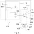
- Fig.2 shows schematically a second embodiment of a drive device 101.
- the reference numerals of similar or identical components compared to the Fig.1 shown embodiment are incremented by 100.
- the supply circuit 103 comprises a switching element 110 which is connected between the first electrical supply line 104 and the second electrical supply line 105 in parallel to the motor 102 and is designed as a bipolar transistor.
- a diode 111 is connected in series with the bipolar transistor 110, as in the first embodiment of Fig.1 .
- the bipolar transistor 110 is designed as an npn transistor, wherein the base B is connected to a switching control device 113.
- the switching control device 113 is part of a switching control circuit 112, wherein a logic unit 115 is connected in parallel to the switching control device 113.
- the switching control circuit 113 further comprises a voltage supply 114, which supplies both the logic unit 115 and the switching control device 113 with power.
- the switching control device 113 provides a control voltage at the base B of the bipolar transistor 110, so that the electrical resistance between the first electrical supply line 104 and the second electrical supply line 105 can be regulated via the switching control device 113.
- the first supply line 104 is connected to the collector C and the diode 110 to the emitter E of the bipolar transistor 110. This creates the possibility of short-circuiting the first supply line 104 and the second electrical supply line 105 by means of the control voltage provided by the switching control device 113, which is applied to the base B.
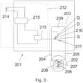
- Fig.3 shows a third embodiment of a drive device 201.
- the drive device 201 is essentially similar to the one shown in Fig.2 shown second embodiment, wherein the switching element 210 designed as a transistor is now designed as a unipolar transistor or MOSFET.
- the gate G of the transistor 210 is coupled to the switching control device 213, wherein the switching control device 213 provides a control voltage to the gate G and thus controls the electrical resistance.
- the source connection S is connected to the diode 211 and the drain connection D is connected to the first electrical supply line 204.
- Fig.1 shows the drive device 1 during normal operation.
- the switching element 10 is in an open position so that the motor 2 can be supplied with power via the supply circuit 3.
- the switching element 10 designed as a normally closed contact is brought into the closed position shown in dashed lines via the switching control device 13 designed as a relay, so that the first electrical supply line 4 and the second electrical supply line 5 are short-circuited at least in the direction from the first electrical supply line 4 to the second electrical supply line 5 via the diode 11.
- This state corresponds to a fail-safe mode, as is provided in the event of a power failure in the vehicle or even damage to the drive device 1.
- the diode 11 designed as a freewheeling diode, is connected in the forward direction in the direction from the first electrical supply line 4 to the second electrical supply line 5, so that the drive device 1 or the motor 2 is braked or locked in the closing direction of the vehicle flap and at the same time can be moved manually in the opening direction of the vehicle flap without great resistance.
- This makes it possible for the user to open a vehicle flap designed as a side door, for example, when the vehicle is on a hill and the side door must be prevented from falling back into the lock due to the large gravitational moment.
Landscapes
- Engineering & Computer Science (AREA)
- Power Engineering (AREA)
- Power-Operated Mechanisms For Wings (AREA)
- Control Of Direct Current Motors (AREA)
Applications Claiming Priority (2)
| Application Number | Priority Date | Filing Date | Title |
|---|---|---|---|
| DE202017105031.9U DE202017105031U1 (de) | 2017-08-22 | 2017-08-22 | Antriebsvorrichtung für eine Fahrzeugklappe |
| PCT/DE2018/100714 WO2019037817A1 (de) | 2017-08-22 | 2018-08-15 | Antriebsvorrichtung für eine fahrzeugklappe |
Publications (2)
| Publication Number | Publication Date |
|---|---|
| EP3673133A1 EP3673133A1 (de) | 2020-07-01 |
| EP3673133B1 true EP3673133B1 (de) | 2024-04-24 |
Family
ID=59885602
Family Applications (1)
| Application Number | Title | Priority Date | Filing Date |
|---|---|---|---|
| EP18765549.3A Active EP3673133B1 (de) | 2017-08-22 | 2018-08-15 | Antriebsvorrichtung für eine fahrzeugklappe |
Country Status (6)
Families Citing this family (3)
| Publication number | Priority date | Publication date | Assignee | Title |
|---|---|---|---|---|
| DE102018112978A1 (de) | 2018-05-30 | 2019-12-05 | Brose Fahrzeugteile Gmbh & Co. Kommanditgesellschaft, Bamberg | Verfahren zur Ansteuerung einer Klappenanordnung eines Kraftfahrzeugs |
| DE102019218172A1 (de) * | 2019-11-25 | 2021-05-27 | Vitesco Technologies GmbH | Aktuator für eine Seitentür eines Kraftfahrzeuges mit Haltefunktion |
| DE102022121749B4 (de) * | 2022-08-29 | 2024-05-29 | Audi Aktiengesellschaft | Kraftfahrzeug und Verfahren zum Betreiben eines Kraftfahrzeugs |
Citations (1)
| Publication number | Priority date | Publication date | Assignee | Title |
|---|---|---|---|---|
| DE102009042456A1 (de) * | 2009-09-23 | 2011-09-08 | Stabilus Gmbh | Antriebseinrichtung |
Family Cites Families (19)
| Publication number | Priority date | Publication date | Assignee | Title |
|---|---|---|---|---|
| JPH1199057A (ja) * | 1997-09-26 | 1999-04-13 | Toyota Auto Body Co Ltd | リニアモータ式カーテン開閉装置 |
| US6175204B1 (en) * | 1998-11-25 | 2001-01-16 | Westinghouse Air Brake Company | Dynamic brake for power door |
| US6198241B1 (en) * | 1999-07-07 | 2001-03-06 | Westinghouse Air Brake Company | Motor protection for a powered door system |
| EP1282222A3 (de) * | 2001-08-04 | 2005-01-12 | NexPress Solutions LLC | Vorrichtung zur Erzeugung oder Steuerung eines Wechselstromes in wenigstens einer induktiven Last |
| US7075257B2 (en) * | 2002-10-18 | 2006-07-11 | Black & Decker Inc. | Method and device for braking a motor |
| DE10261225B4 (de) * | 2002-12-20 | 2006-11-16 | Dorma Gmbh + Co. Kg | Elektrohydraulischer Servotürantrieb zum Antrieb einer Tür, eines Fensters oder dergleichen |
| US6839242B2 (en) * | 2003-02-13 | 2005-01-04 | Rincon Research Corporation | Reconfigurable circuit modules |
| EP1783309A2 (de) * | 2005-11-07 | 2007-05-09 | Pierburg GmbH | Verfahren zur Anschlagdämpfung einer Stellvorrichtung sowie Stellvorrichtung für eine Verbrennungskraftmaschine |
| ITRM20060085U1 (it) * | 2006-05-17 | 2007-11-18 | Findisa S R L | Sistema oleodinamico a bassa tensione a controllo elettronico di movimentazione di chiusure automatiche |
| JP5275755B2 (ja) * | 2008-11-04 | 2013-08-28 | 文化シヤッター株式会社 | 開閉装置 |
| US8704468B2 (en) * | 2009-03-03 | 2014-04-22 | Robert Bosch Gmbh | Electrodynamic braking device for a universal motor |
| US8484892B2 (en) * | 2011-05-19 | 2013-07-16 | Wabtec Holding Corp. | Electric door operator |
| CN102923158A (zh) * | 2011-08-12 | 2013-02-13 | 陈耕田 | 轨道列车紧急制动安全系统 |
| JP6303212B2 (ja) * | 2013-10-08 | 2018-04-04 | 三井金属アクト株式会社 | 車両用ドアの開閉制御装置 |
| JP2015122610A (ja) * | 2013-12-24 | 2015-07-02 | ボッシュ株式会社 | フライバック回路 |
| JP6248799B2 (ja) * | 2014-05-16 | 2017-12-20 | 株式会社オートネットワーク技術研究所 | 蓄電装置 |
| AT515888A3 (de) * | 2014-05-22 | 2019-01-15 | Knorr Bremse Gmbh | Elektronische Schaltung zur sicheren Schließung einer motorisch angetriebenen Tür eines Schienenfahrzeugs |
| JP6218189B2 (ja) * | 2015-07-08 | 2017-10-25 | オムロンオートモーティブエレクトロニクス株式会社 | 操作補助制御装置 |
| DE102015112807A1 (de) | 2015-08-04 | 2017-02-09 | Stabilus Gmbh | Elektromechanischer Antieb |
-
2017
- 2017-08-22 DE DE202017105031.9U patent/DE202017105031U1/de active Active
-
2018
- 2018-08-15 JP JP2020511355A patent/JP7223747B2/ja active Active
- 2018-08-15 DE DE112018004707.5T patent/DE112018004707A5/de not_active Withdrawn
- 2018-08-15 WO PCT/DE2018/100714 patent/WO2019037817A1/de unknown
- 2018-08-15 US US16/640,591 patent/US11199039B2/en active Active
- 2018-08-15 EP EP18765549.3A patent/EP3673133B1/de active Active
- 2018-08-15 CN CN201880053984.6A patent/CN111183266B/zh active Active
Patent Citations (1)
| Publication number | Priority date | Publication date | Assignee | Title |
|---|---|---|---|---|
| DE102009042456A1 (de) * | 2009-09-23 | 2011-09-08 | Stabilus Gmbh | Antriebseinrichtung |
Also Published As
| Publication number | Publication date |
|---|---|
| CN111183266A (zh) | 2020-05-19 |
| US11199039B2 (en) | 2021-12-14 |
| US20200173220A1 (en) | 2020-06-04 |
| CN111183266B (zh) | 2021-09-24 |
| JP2020531719A (ja) | 2020-11-05 |
| WO2019037817A1 (de) | 2019-02-28 |
| DE112018004707A5 (de) | 2020-09-10 |
| DE202017105031U1 (de) | 2017-08-29 |
| JP7223747B2 (ja) | 2023-02-16 |
| EP3673133A1 (de) | 2020-07-01 |
Similar Documents
| Publication | Publication Date | Title |
|---|---|---|
| DE102008057014B4 (de) | Antriebsanordnung zur motorischen Verstellung eines Verschlusselements in einem Kraftfahrzeug | |
| EP2267881B1 (de) | Bremsschaltung für einen Türbetätiger mit einem generatorisch betreibbaren Elektromotor | |
| EP2389491B1 (de) | Antriebsanordnung zur motorischen verstellung eines verstellelements eines kraftfahrzeugs | |
| EP3673133B1 (de) | Antriebsvorrichtung für eine fahrzeugklappe | |
| DE202017007582U1 (de) | Stellvorrichtung | |
| DE102016209915A1 (de) | Verstellantrieb eines Kraftfahrzeugs | |
| DE102011112273A1 (de) | Antriebsanordnung zur motorischen Verstellung eines Verstellelements eines Kraftfahrzeugs | |
| DE102007059492A1 (de) | Industrieroboter | |
| DE102011087120B4 (de) | Stellantrieb einer Luftdurchlassvorrichtung | |
| DE102013108258A1 (de) | Antriebssystem für einen Fahrzeuganhängerrangierantrieb | |
| EP2220317A1 (de) | Antriebsvorrichtung fuer ein- und ausstiegseinrichtungen | |
| EP3231976A1 (de) | Sicherheitsschaltung für einen drehantrieb | |
| CH685221A5 (de) | Antrieb für Türen, Tore oder Klappen. | |
| EP0468361B1 (de) | Begrenzung der Schliesskraft an der Schliesskante eines beweglichen Elementes | |
| EP1985522A1 (de) | Schutzeinrichtung für eine Hilfskraftlenkung | |
| DE102018112978A1 (de) | Verfahren zur Ansteuerung einer Klappenanordnung eines Kraftfahrzeugs | |
| DE102016119959A1 (de) | Antriebsanordnung | |
| DE102021114184A1 (de) | Antriebseinheit für ein Verschlusselement eines Kraftfahrzeugs | |
| DE69116226T2 (de) | Schaltkreis für elektromechanische Betätigungsvorrichtung und Betätigungsvorrichtung unter Verwendung dieses Schaltkreises | |
| DE1530992A1 (de) | Vorrichtung zum OEffnen und Schliessen von Tueren,Schiebedaechern od.dgl.,insbesondere von Kraftfahrzeugen | |
| EP1244564A1 (de) | Elektrische schaltungsanordnung zur steuerung eines elektromotors in einem kraftfahrzeug | |
| EP2009312B1 (de) | Elektrisch betriebener Kupplungsaktor | |
| EP3426868B1 (de) | Kraftfahrzeugschloss mit schliesshilfe | |
| EP4557601A1 (de) | Antriebsmotor für dreh- und schiebetürantriebe mit integrierter elektronik und sicherheitsfunktionen | |
| DE102016115773B3 (de) | Torantriebsvorrichtung mit Zuluftfunktion für ein Tor, insbesondere für ein Rauch- oder Wärmeabzugssystem, damit angetriebenes Tor sowie Nachrüstsatz |
Legal Events
| Date | Code | Title | Description |
|---|---|---|---|
| STAA | Information on the status of an ep patent application or granted ep patent |
Free format text: STATUS: UNKNOWN |
|
| STAA | Information on the status of an ep patent application or granted ep patent |
Free format text: STATUS: THE INTERNATIONAL PUBLICATION HAS BEEN MADE |
|
| PUAI | Public reference made under article 153(3) epc to a published international application that has entered the european phase |
Free format text: ORIGINAL CODE: 0009012 |
|
| STAA | Information on the status of an ep patent application or granted ep patent |
Free format text: STATUS: REQUEST FOR EXAMINATION WAS MADE |
|
| 17P | Request for examination filed |
Effective date: 20200303 |
|
| AK | Designated contracting states |
Kind code of ref document: A1 Designated state(s): AL AT BE BG CH CY CZ DE DK EE ES FI FR GB GR HR HU IE IS IT LI LT LU LV MC MK MT NL NO PL PT RO RS SE SI SK SM TR |
|
| AX | Request for extension of the european patent |
Extension state: BA ME |
|
| STAA | Information on the status of an ep patent application or granted ep patent |
Free format text: STATUS: EXAMINATION IS IN PROGRESS |
|
| STAA | Information on the status of an ep patent application or granted ep patent |
Free format text: STATUS: EXAMINATION IS IN PROGRESS |
|
| DAV | Request for validation of the european patent (deleted) | ||
| DAX | Request for extension of the european patent (deleted) | ||
| 17Q | First examination report despatched |
Effective date: 20201117 |
|
| RIC1 | Information provided on ipc code assigned before grant |
Ipc: H02H 7/085 20060101ALI20231006BHEP Ipc: E05F 15/611 20150101AFI20231006BHEP |
|
| GRAP | Despatch of communication of intention to grant a patent |
Free format text: ORIGINAL CODE: EPIDOSNIGR1 |
|
| STAA | Information on the status of an ep patent application or granted ep patent |
Free format text: STATUS: GRANT OF PATENT IS INTENDED |
|
| INTG | Intention to grant announced |
Effective date: 20231122 |
|
| GRAS | Grant fee paid |
Free format text: ORIGINAL CODE: EPIDOSNIGR3 |
|
| GRAA | (expected) grant |
Free format text: ORIGINAL CODE: 0009210 |
|
| STAA | Information on the status of an ep patent application or granted ep patent |
Free format text: STATUS: THE PATENT HAS BEEN GRANTED |
|
| P01 | Opt-out of the competence of the unified patent court (upc) registered |
Effective date: 20240311 |
|
| AK | Designated contracting states |
Kind code of ref document: B1 Designated state(s): AL AT BE BG CH CY CZ DE DK EE ES FI FR GB GR HR HU IE IS IT LI LT LU LV MC MK MT NL NO PL PT RO RS SE SI SK SM TR |
|
| REG | Reference to a national code |
Ref country code: GB Ref legal event code: FG4D Free format text: NOT ENGLISH |
|
| REG | Reference to a national code |
Ref country code: CH Ref legal event code: EP |
|
| REG | Reference to a national code |
Ref country code: DE Ref legal event code: R096 Ref document number: 502018014491 Country of ref document: DE |
|
| REG | Reference to a national code |
Ref country code: IE Ref legal event code: FG4D Free format text: LANGUAGE OF EP DOCUMENT: GERMAN |
|
| REG | Reference to a national code |
Ref country code: LT Ref legal event code: MG9D |
|
| REG | Reference to a national code |
Ref country code: NL Ref legal event code: MP Effective date: 20240424 |
|
| PG25 | Lapsed in a contracting state [announced via postgrant information from national office to epo] |
Ref country code: NL Free format text: LAPSE BECAUSE OF FAILURE TO SUBMIT A TRANSLATION OF THE DESCRIPTION OR TO PAY THE FEE WITHIN THE PRESCRIBED TIME-LIMIT Effective date: 20240424 |
|
| PG25 | Lapsed in a contracting state [announced via postgrant information from national office to epo] |
Ref country code: NL Free format text: LAPSE BECAUSE OF FAILURE TO SUBMIT A TRANSLATION OF THE DESCRIPTION OR TO PAY THE FEE WITHIN THE PRESCRIBED TIME-LIMIT Effective date: 20240424 |
|
| PG25 | Lapsed in a contracting state [announced via postgrant information from national office to epo] |
Ref country code: IS Free format text: LAPSE BECAUSE OF FAILURE TO SUBMIT A TRANSLATION OF THE DESCRIPTION OR TO PAY THE FEE WITHIN THE PRESCRIBED TIME-LIMIT Effective date: 20240824 |
|
| PG25 | Lapsed in a contracting state [announced via postgrant information from national office to epo] |
Ref country code: BG Free format text: LAPSE BECAUSE OF FAILURE TO SUBMIT A TRANSLATION OF THE DESCRIPTION OR TO PAY THE FEE WITHIN THE PRESCRIBED TIME-LIMIT Effective date: 20240424 |
|
| PG25 | Lapsed in a contracting state [announced via postgrant information from national office to epo] |
Ref country code: FI Free format text: LAPSE BECAUSE OF FAILURE TO SUBMIT A TRANSLATION OF THE DESCRIPTION OR TO PAY THE FEE WITHIN THE PRESCRIBED TIME-LIMIT Effective date: 20240424 Ref country code: HR Free format text: LAPSE BECAUSE OF FAILURE TO SUBMIT A TRANSLATION OF THE DESCRIPTION OR TO PAY THE FEE WITHIN THE PRESCRIBED TIME-LIMIT Effective date: 20240424 |
|
| PGFP | Annual fee paid to national office [announced via postgrant information from national office to epo] |
Ref country code: DE Payment date: 20240821 Year of fee payment: 7 |
|
| PG25 | Lapsed in a contracting state [announced via postgrant information from national office to epo] |
Ref country code: GR Free format text: LAPSE BECAUSE OF FAILURE TO SUBMIT A TRANSLATION OF THE DESCRIPTION OR TO PAY THE FEE WITHIN THE PRESCRIBED TIME-LIMIT Effective date: 20240725 |
|
| PG25 | Lapsed in a contracting state [announced via postgrant information from national office to epo] |
Ref country code: PT Free format text: LAPSE BECAUSE OF FAILURE TO SUBMIT A TRANSLATION OF THE DESCRIPTION OR TO PAY THE FEE WITHIN THE PRESCRIBED TIME-LIMIT Effective date: 20240826 |
|
| PG25 | Lapsed in a contracting state [announced via postgrant information from national office to epo] |
Ref country code: ES Free format text: LAPSE BECAUSE OF FAILURE TO SUBMIT A TRANSLATION OF THE DESCRIPTION OR TO PAY THE FEE WITHIN THE PRESCRIBED TIME-LIMIT Effective date: 20240424 |
|
| PG25 | Lapsed in a contracting state [announced via postgrant information from national office to epo] |
Ref country code: PL Free format text: LAPSE BECAUSE OF FAILURE TO SUBMIT A TRANSLATION OF THE DESCRIPTION OR TO PAY THE FEE WITHIN THE PRESCRIBED TIME-LIMIT Effective date: 20240424 |
|
| PG25 | Lapsed in a contracting state [announced via postgrant information from national office to epo] |
Ref country code: LV Free format text: LAPSE BECAUSE OF FAILURE TO SUBMIT A TRANSLATION OF THE DESCRIPTION OR TO PAY THE FEE WITHIN THE PRESCRIBED TIME-LIMIT Effective date: 20240424 |
|
| PG25 | Lapsed in a contracting state [announced via postgrant information from national office to epo] |
Ref country code: PT Free format text: LAPSE BECAUSE OF FAILURE TO SUBMIT A TRANSLATION OF THE DESCRIPTION OR TO PAY THE FEE WITHIN THE PRESCRIBED TIME-LIMIT Effective date: 20240826 Ref country code: PL Free format text: LAPSE BECAUSE OF FAILURE TO SUBMIT A TRANSLATION OF THE DESCRIPTION OR TO PAY THE FEE WITHIN THE PRESCRIBED TIME-LIMIT Effective date: 20240424 Ref country code: NO Free format text: LAPSE BECAUSE OF FAILURE TO SUBMIT A TRANSLATION OF THE DESCRIPTION OR TO PAY THE FEE WITHIN THE PRESCRIBED TIME-LIMIT Effective date: 20240724 Ref country code: LV Free format text: LAPSE BECAUSE OF FAILURE TO SUBMIT A TRANSLATION OF THE DESCRIPTION OR TO PAY THE FEE WITHIN THE PRESCRIBED TIME-LIMIT Effective date: 20240424 Ref country code: IS Free format text: LAPSE BECAUSE OF FAILURE TO SUBMIT A TRANSLATION OF THE DESCRIPTION OR TO PAY THE FEE WITHIN THE PRESCRIBED TIME-LIMIT Effective date: 20240824 Ref country code: HR Free format text: LAPSE BECAUSE OF FAILURE TO SUBMIT A TRANSLATION OF THE DESCRIPTION OR TO PAY THE FEE WITHIN THE PRESCRIBED TIME-LIMIT Effective date: 20240424 Ref country code: GR Free format text: LAPSE BECAUSE OF FAILURE TO SUBMIT A TRANSLATION OF THE DESCRIPTION OR TO PAY THE FEE WITHIN THE PRESCRIBED TIME-LIMIT Effective date: 20240725 Ref country code: FI Free format text: LAPSE BECAUSE OF FAILURE TO SUBMIT A TRANSLATION OF THE DESCRIPTION OR TO PAY THE FEE WITHIN THE PRESCRIBED TIME-LIMIT Effective date: 20240424 Ref country code: ES Free format text: LAPSE BECAUSE OF FAILURE TO SUBMIT A TRANSLATION OF THE DESCRIPTION OR TO PAY THE FEE WITHIN THE PRESCRIBED TIME-LIMIT Effective date: 20240424 Ref country code: BG Free format text: LAPSE BECAUSE OF FAILURE TO SUBMIT A TRANSLATION OF THE DESCRIPTION OR TO PAY THE FEE WITHIN THE PRESCRIBED TIME-LIMIT Effective date: 20240424 Ref country code: RS Free format text: LAPSE BECAUSE OF FAILURE TO SUBMIT A TRANSLATION OF THE DESCRIPTION OR TO PAY THE FEE WITHIN THE PRESCRIBED TIME-LIMIT Effective date: 20240724 |
|
| PG25 | Lapsed in a contracting state [announced via postgrant information from national office to epo] |
Ref country code: DK Free format text: LAPSE BECAUSE OF FAILURE TO SUBMIT A TRANSLATION OF THE DESCRIPTION OR TO PAY THE FEE WITHIN THE PRESCRIBED TIME-LIMIT Effective date: 20240424 |
|
| PG25 | Lapsed in a contracting state [announced via postgrant information from national office to epo] |
Ref country code: EE Free format text: LAPSE BECAUSE OF FAILURE TO SUBMIT A TRANSLATION OF THE DESCRIPTION OR TO PAY THE FEE WITHIN THE PRESCRIBED TIME-LIMIT Effective date: 20240424 |
|
| PG25 | Lapsed in a contracting state [announced via postgrant information from national office to epo] |
Ref country code: CZ Free format text: LAPSE BECAUSE OF FAILURE TO SUBMIT A TRANSLATION OF THE DESCRIPTION OR TO PAY THE FEE WITHIN THE PRESCRIBED TIME-LIMIT Effective date: 20240424 |
|
| PG25 | Lapsed in a contracting state [announced via postgrant information from national office to epo] |
Ref country code: SK Free format text: LAPSE BECAUSE OF FAILURE TO SUBMIT A TRANSLATION OF THE DESCRIPTION OR TO PAY THE FEE WITHIN THE PRESCRIBED TIME-LIMIT Effective date: 20240424 Ref country code: RO Free format text: LAPSE BECAUSE OF FAILURE TO SUBMIT A TRANSLATION OF THE DESCRIPTION OR TO PAY THE FEE WITHIN THE PRESCRIBED TIME-LIMIT Effective date: 20240424 |
|
| REG | Reference to a national code |
Ref country code: DE Ref legal event code: R097 Ref document number: 502018014491 Country of ref document: DE |
|
| PG25 | Lapsed in a contracting state [announced via postgrant information from national office to epo] |
Ref country code: SM Free format text: LAPSE BECAUSE OF FAILURE TO SUBMIT A TRANSLATION OF THE DESCRIPTION OR TO PAY THE FEE WITHIN THE PRESCRIBED TIME-LIMIT Effective date: 20240424 |
|
| PG25 | Lapsed in a contracting state [announced via postgrant information from national office to epo] |
Ref country code: SM Free format text: LAPSE BECAUSE OF FAILURE TO SUBMIT A TRANSLATION OF THE DESCRIPTION OR TO PAY THE FEE WITHIN THE PRESCRIBED TIME-LIMIT Effective date: 20240424 Ref country code: SK Free format text: LAPSE BECAUSE OF FAILURE TO SUBMIT A TRANSLATION OF THE DESCRIPTION OR TO PAY THE FEE WITHIN THE PRESCRIBED TIME-LIMIT Effective date: 20240424 Ref country code: RO Free format text: LAPSE BECAUSE OF FAILURE TO SUBMIT A TRANSLATION OF THE DESCRIPTION OR TO PAY THE FEE WITHIN THE PRESCRIBED TIME-LIMIT Effective date: 20240424 Ref country code: EE Free format text: LAPSE BECAUSE OF FAILURE TO SUBMIT A TRANSLATION OF THE DESCRIPTION OR TO PAY THE FEE WITHIN THE PRESCRIBED TIME-LIMIT Effective date: 20240424 Ref country code: DK Free format text: LAPSE BECAUSE OF FAILURE TO SUBMIT A TRANSLATION OF THE DESCRIPTION OR TO PAY THE FEE WITHIN THE PRESCRIBED TIME-LIMIT Effective date: 20240424 Ref country code: CZ Free format text: LAPSE BECAUSE OF FAILURE TO SUBMIT A TRANSLATION OF THE DESCRIPTION OR TO PAY THE FEE WITHIN THE PRESCRIBED TIME-LIMIT Effective date: 20240424 |
|
| PLBE | No opposition filed within time limit |
Free format text: ORIGINAL CODE: 0009261 |
|
| STAA | Information on the status of an ep patent application or granted ep patent |
Free format text: STATUS: NO OPPOSITION FILED WITHIN TIME LIMIT |
|
| REG | Reference to a national code |
Ref country code: CH Ref legal event code: PL |
|
| 26N | No opposition filed |
Effective date: 20250127 |
|
| PG25 | Lapsed in a contracting state [announced via postgrant information from national office to epo] |
Ref country code: LU Free format text: LAPSE BECAUSE OF NON-PAYMENT OF DUE FEES Effective date: 20240815 |
|
| GBPC | Gb: european patent ceased through non-payment of renewal fee |
Effective date: 20240815 |
|
| PG25 | Lapsed in a contracting state [announced via postgrant information from national office to epo] |
Ref country code: SI Free format text: LAPSE BECAUSE OF FAILURE TO SUBMIT A TRANSLATION OF THE DESCRIPTION OR TO PAY THE FEE WITHIN THE PRESCRIBED TIME-LIMIT Effective date: 20240424 Ref country code: MC Free format text: LAPSE BECAUSE OF FAILURE TO SUBMIT A TRANSLATION OF THE DESCRIPTION OR TO PAY THE FEE WITHIN THE PRESCRIBED TIME-LIMIT Effective date: 20240424 Ref country code: CH Free format text: LAPSE BECAUSE OF NON-PAYMENT OF DUE FEES Effective date: 20240831 |
|
| REG | Reference to a national code |
Ref country code: BE Ref legal event code: MM Effective date: 20240831 |
|
| PG25 | Lapsed in a contracting state [announced via postgrant information from national office to epo] |
Ref country code: GB Free format text: LAPSE BECAUSE OF NON-PAYMENT OF DUE FEES Effective date: 20240815 |
|
| PG25 | Lapsed in a contracting state [announced via postgrant information from national office to epo] |
Ref country code: BE Free format text: LAPSE BECAUSE OF NON-PAYMENT OF DUE FEES Effective date: 20240831 |
|
| PG25 | Lapsed in a contracting state [announced via postgrant information from national office to epo] |
Ref country code: FR Free format text: LAPSE BECAUSE OF NON-PAYMENT OF DUE FEES Effective date: 20240831 |
|
| PG25 | Lapsed in a contracting state [announced via postgrant information from national office to epo] |
Ref country code: IE Free format text: LAPSE BECAUSE OF NON-PAYMENT OF DUE FEES Effective date: 20240815 |