EP3671896A1 - Vorrichtung und verfahren zur montage von batteriezellen - Google Patents
Vorrichtung und verfahren zur montage von batteriezellen Download PDFInfo
- Publication number
- EP3671896A1 EP3671896A1 EP19810028.1A EP19810028A EP3671896A1 EP 3671896 A1 EP3671896 A1 EP 3671896A1 EP 19810028 A EP19810028 A EP 19810028A EP 3671896 A1 EP3671896 A1 EP 3671896A1
- Authority
- EP
- European Patent Office
- Prior art keywords
- film
- battery cell
- frame
- cell stack
- mounting
- Prior art date
- Legal status (The legal status is an assumption and is not a legal conclusion. Google has not performed a legal analysis and makes no representation as to the accuracy of the status listed.)
- Granted
Links
Images


Classifications
-
- H—ELECTRICITY
- H01—ELECTRIC ELEMENTS
- H01M—PROCESSES OR MEANS, e.g. BATTERIES, FOR THE DIRECT CONVERSION OF CHEMICAL ENERGY INTO ELECTRICAL ENERGY
- H01M10/00—Secondary cells; Manufacture thereof
- H01M10/04—Construction or manufacture in general
- H01M10/0486—Frames for plates or membranes
-
- H—ELECTRICITY
- H01—ELECTRIC ELEMENTS
- H01M—PROCESSES OR MEANS, e.g. BATTERIES, FOR THE DIRECT CONVERSION OF CHEMICAL ENERGY INTO ELECTRICAL ENERGY
- H01M50/00—Constructional details or processes of manufacture of the non-active parts of electrochemical cells other than fuel cells, e.g. hybrid cells
- H01M50/20—Mountings; Secondary casings or frames; Racks, modules or packs; Suspension devices; Shock absorbers; Transport or carrying devices; Holders
-
- B—PERFORMING OPERATIONS; TRANSPORTING
- B29—WORKING OF PLASTICS; WORKING OF SUBSTANCES IN A PLASTIC STATE IN GENERAL
- B29C—SHAPING OR JOINING OF PLASTICS; SHAPING OF MATERIAL IN A PLASTIC STATE, NOT OTHERWISE PROVIDED FOR; AFTER-TREATMENT OF THE SHAPED PRODUCTS, e.g. REPAIRING
- B29C66/00—General aspects of processes or apparatus for joining preformed parts
- B29C66/80—General aspects of machine operations or constructions and parts thereof
- B29C66/83—General aspects of machine operations or constructions and parts thereof characterised by the movement of the joining or pressing tools
- B29C66/834—General aspects of machine operations or constructions and parts thereof characterised by the movement of the joining or pressing tools moving with the parts to be joined
- B29C66/8341—Roller, cylinder or drum types; Band or belt types; Ball types
- B29C66/83431—Roller, cylinder or drum types; Band or belt types; Ball types rollers, cylinders or drums cooperating with bands or belts
-
- H—ELECTRICITY
- H01—ELECTRIC ELEMENTS
- H01M—PROCESSES OR MEANS, e.g. BATTERIES, FOR THE DIRECT CONVERSION OF CHEMICAL ENERGY INTO ELECTRICAL ENERGY
- H01M50/00—Constructional details or processes of manufacture of the non-active parts of electrochemical cells other than fuel cells, e.g. hybrid cells
- H01M50/20—Mountings; Secondary casings or frames; Racks, modules or packs; Suspension devices; Shock absorbers; Transport or carrying devices; Holders
- H01M50/204—Racks, modules or packs for multiple batteries or multiple cells
- H01M50/207—Racks, modules or packs for multiple batteries or multiple cells characterised by their shape
- H01M50/209—Racks, modules or packs for multiple batteries or multiple cells characterised by their shape adapted for prismatic or rectangular cells
-
- H—ELECTRICITY
- H01—ELECTRIC ELEMENTS
- H01M—PROCESSES OR MEANS, e.g. BATTERIES, FOR THE DIRECT CONVERSION OF CHEMICAL ENERGY INTO ELECTRICAL ENERGY
- H01M50/00—Constructional details or processes of manufacture of the non-active parts of electrochemical cells other than fuel cells, e.g. hybrid cells
- H01M50/20—Mountings; Secondary casings or frames; Racks, modules or packs; Suspension devices; Shock absorbers; Transport or carrying devices; Holders
- H01M50/244—Secondary casings; Racks; Suspension devices; Carrying devices; Holders characterised by their mounting method
-
- B—PERFORMING OPERATIONS; TRANSPORTING
- B29—WORKING OF PLASTICS; WORKING OF SUBSTANCES IN A PLASTIC STATE IN GENERAL
- B29L—INDEXING SCHEME ASSOCIATED WITH SUBCLASS B29C, RELATING TO PARTICULAR ARTICLES
- B29L2031/00—Other particular articles
- B29L2031/34—Electrical apparatus, e.g. sparking plugs or parts thereof
- B29L2031/3468—Batteries, accumulators or fuel cells
-
- Y—GENERAL TAGGING OF NEW TECHNOLOGICAL DEVELOPMENTS; GENERAL TAGGING OF CROSS-SECTIONAL TECHNOLOGIES SPANNING OVER SEVERAL SECTIONS OF THE IPC; TECHNICAL SUBJECTS COVERED BY FORMER USPC CROSS-REFERENCE ART COLLECTIONS [XRACs] AND DIGESTS
- Y02—TECHNOLOGIES OR APPLICATIONS FOR MITIGATION OR ADAPTATION AGAINST CLIMATE CHANGE
- Y02E—REDUCTION OF GREENHOUSE GAS [GHG] EMISSIONS, RELATED TO ENERGY GENERATION, TRANSMISSION OR DISTRIBUTION
- Y02E60/00—Enabling technologies; Technologies with a potential or indirect contribution to GHG emissions mitigation
- Y02E60/10—Energy storage using batteries
-
- Y—GENERAL TAGGING OF NEW TECHNOLOGICAL DEVELOPMENTS; GENERAL TAGGING OF CROSS-SECTIONAL TECHNOLOGIES SPANNING OVER SEVERAL SECTIONS OF THE IPC; TECHNICAL SUBJECTS COVERED BY FORMER USPC CROSS-REFERENCE ART COLLECTIONS [XRACs] AND DIGESTS
- Y02—TECHNOLOGIES OR APPLICATIONS FOR MITIGATION OR ADAPTATION AGAINST CLIMATE CHANGE
- Y02P—CLIMATE CHANGE MITIGATION TECHNOLOGIES IN THE PRODUCTION OR PROCESSING OF GOODS
- Y02P70/00—Climate change mitigation technologies in the production process for final industrial or consumer products
- Y02P70/50—Manufacturing or production processes characterised by the final manufactured product
Definitions
- the present disclosure relates to an apparatus and method for mounting a battery cell, and more particularly, to an apparatus and method for mounting a battery cell, which allows a battery cell stack to be mounted to a frame without deforming the frame.
- a nickel-cadmium battery or a hydrogen ion battery has been used as the secondary battery.
- a lithium secondary battery is recently widely used because charging and discharging is free due to rare memory effect in comparison with a nickel-based secondary battery, a self-discharge rate is very low, and an energy density is high.
- the lithium secondary battery mainly uses a lithium oxide and a carbonaceous material as a positive electrode active material and a negative electrode active material, respectively.
- the lithium secondary battery includes an electrode assembly in which a positive electrode plate and a negative electrode plate, respectively coated with the positive electrode active material and the negative electrode active material, are arranged with a separator therebetween, and an outer member, that is a battery case, which seals and receives the electrode assembly together with an electrolyte solution.
- the lithium secondary battery includes a positive electrode, a negative electrode, and a separator interposed therebetween and an electrolyte.
- the lithium secondary battery is classified into a lithium ion battery (LIB) and a polymer lithium ion battery (PLIB).
- LIB lithium ion battery
- PKIB polymer lithium ion battery
- an electrode of the lithium secondary battery is prepared by applying the positive or negative electrode active material to a current collector made of aluminum or copper sheet, mesh, film, foil, or the like and then drying the same.
- a battery cell stack may be mounted to a frames of various shapes.
- the frame has a U shape, it is not easy to mount the battery cell stack to the frame.
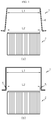
- FIGS. 1(a) and 1(b) are diagrams for illustrating a method of inserting a battery cell stack into a U-shaped frame.
- an inner length L1 of the U-shaped frame 1 is identical or extremely similar to an entire length L2 of a battery cell stack 2, and namely, there is substantially no clearance.
- the battery cell stack 2 is inserted into the U-shaped frame 1 in a state where a side cover 4 of the frame 1 is deformed to spread outward by applying an external force to the side cover 4 of the U-shaped frame 1 outward.
- the U-shaped frame 1 may be permanently deformed, and the U-shaped frame 1 may be distorted.
- the battery cell stack 2 may be easily mounted to the U-shaped frame 1.
- the space 5 between the U-shaped frame 1 and the battery cell stack 2 it is not easy to fix the battery cell stack 2 to the U-shaped frame 1, and the space utilization of the battery module is low since the total volume of the battery module increases.
- the present disclosure is designed to solve the problems of the related art, and therefore the present disclosure is directed to providing an apparatus and method for mounting a battery cell, which may allow a battery cell stack to be mounted to a frame without deforming or distorting the frame.
- the present disclosure is directed to providing an apparatus and method for mounting a battery cell, which may prevent the space utilization of the battery from deteriorating.
- the present disclosure is directed to providing an apparatus and method for mounting a battery cell, which may allow the battery cell stack to be mounted to the frame without damaging the battery cell stack.
- an apparatus for mounting a battery cell which mounts a battery cell stack to a frame that includes a base cover and a pair of side covers respectively extending from both ends of the base cover, the apparatus comprising: a support member to which the battery cell stack is supported; a roller member around which a film fixed to the support member is wound; and a film guide member configured to move the film wound around the roller member into the frame, wherein the film guide member moves the film into the frame, the support member and the frame move close to each other, and the battery cell stack moves along the film to be mounted to the frame.
- the support member may include: a first support portion on which the battery cell stack is placed; and a second support portion formed longer than the first support portion and coupled to both ends of the first support portion, the film being fixed to the second support portion.
- the film guide member may be disposed so that the film is located between the frame and the film guide member, and the film guide member may contact the film and move the film into the frame.
- the apparatus may further comprise a pressing member configured to move toward the support member at a position spaced apart from the support member to press a side surface of the battery cell stack.
- the pressing member may include: a movable rod configured to be movable and having a height corresponding to the height of the battery cell stack based on a direction in which the battery cell stack is supported by the support member; at least one rotating roller coupled to the movable rod and configured to contact the film at the side surface of the battery cell stack; and a driving force transmission source coupled to the movable rod to transmit a driving force to the movable rod.
- the apparatus may further comprise a film damage prevention member disposed to be movable between the frame and the roller member and configured to move toward the film and contact the film.
- a round portion may be formed at an edge of the film damage prevention member at which the film damage prevention member contacts the film.
- the apparatus may further comprise a heat conduction member coupled to the battery cell stack.
- a method for mounting a battery cell which mounts a battery cell stack to a frame that includes a base cover and a pair of side covers respectively extending from both ends of the base cover, the method comprising: providing a battery cell stack to be supported by a support member; by a film guide member, moving a film fixed to the support member and wound around a roller member into the frame; moving the support member and the frame close to each other; moving the battery cell stack along the film to be inserted into the frame; removing the film guide member from the film; and drawing the film from the inside of the frame by a rotation of the roller member.
- the method may further comprise moving a pressing member toward the support member at a position spaced apart from the support member to press a side surface of the battery cell stack.
- the method may further comprise moving a film damage prevention member toward the film to contact the film.
- the battery cell stack since the battery cell stack is mounted to the frame along a film, the battery cell stack may be mounted to the frame without deforming or distorting the frame.
- the battery cell stack since the battery cell stack is inserted into the frame while sliding along the film, the battery cell stack may be mounted to the frame without being damaged.
- 'combine' or 'connect' may refer not only to a case where one member and another member are directly combined or directly connected but also a case where one member is indirectly combined with another member via a connecting member or is indirectly connected.
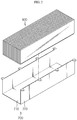
- FIG. 2 is a schematic perspective view showing that a battery cell stack is separated from a frame
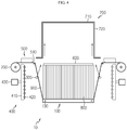
- FIG. 3 is a schematic perspective view showing a support member in an apparatus for mounting a battery cell according to an embodiment of the present disclosure
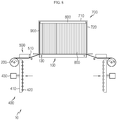
- FIG. 4 is a schematic side view showing the apparatus for mounting a battery cell according to an embodiment of the present disclosure
- FIG. 10 is a schematic side view showing an apparatus for mounting a battery cell according to another embodiment of the present disclosure.
- a battery cell stack 800 may be mounted to a frame 700 to form a battery module.
- the frame 700 may have various shapes, and for convenience of explanation, as shown in FIG. 2 , the frame 700 will be described as including a base cover 710 and a pair of side covers 720 extending from both ends of the base cover 710.
- the frame 700 may be formed to have an approximate "U” shape.
- the approximate "U” shape does not necessarily have to be the same as the "U” shape but includes all shapes similar to the "U” shape.
- an apparatus 10 for mounting a battery cell includes a support member 100, a roller member 200 and a film guide member 300.
- the support member 100 supports the battery cell stack 800. That is, referring to FIG. 4 , the battery cell stack 800 may be placed on and supported by an upper side of the support member 100. In addition, one side of a film 900, explained later, may be fixed to the support member 100.
- the support member 100 may move close to the frame 700. That is, the support member 100 may move toward the frame 700 in a state where the battery cell stack 800 is placed thereon, or the frame 700 may move toward the support member 100.
- a predetermined power source may be coupled to the support member 100 to move the support member 100 toward the frame 700.
- the support member 100 may be fixed and the frame 700 may be moved to the support member 100. However, for convenience of explanation, the following description will be based on the case where the support member 100 moves toward the frame 700.
- the support member 100 may include a first support portion 110 and a second support portion 120.
- the battery cell stack 800 is placed on the first support portion 110.
- the battery cell stack 800 may be prepared by coupling a plurality of battery cells in various ways. For example, a plurality of battery cells may be attached to each other by a double-sided tape to form the battery cell stack 800, and the battery cell stack 800 configured as above is placed on an upper side of the first support portion 110 based on FIG. 4 .
- the second support portion 120 is formed longer than the first support portion 110 and is coupled to both ends of the first support portion 110.
- the second support portion 120 may be integrally formed with the first support portion 110, or may be manufactured separately and then coupled to an end portion of the first support portion 110 in various ways.
- a fixed bar 130 may be respectively coupled to two second support portions 120 as shown in FIGS. 3 and 4 , and the film 900 may be fixed to the fixed bar 130.
- both ends of some of the battery cells of the battery cell stack 800 may be placed on and supported by the second support portion 120.
- the roller member 200 is wound with the film 900 fixed to the support member 100.
- one side of the film 900 may be fixed to the fixed bar 130 coupled to the second support portion 120 of the support member 100, and the other side of the film 900 may be wound on the roller member 200 so as to be wound or unwound.
- one side of the film 900 may be fixed to a fixing member 140 disposed apart from the support member 100, and the other side of the film 900 may be wound on the roller member 200 so as to be wound or unwound.
- the roller member 200 is provided to be rotatable, and the film 900 may be wound on the roller member 200 or unwound from the roller member 200 in accordance with the counterclockwise or clockwise rotation of the roller member 200.
- the film guide member 300 moves in contact with the film 900 wound on the roller member 200 and moves the film 900 into the frame 700.
- the film guide member 300 is disposed so that the film 900 is positioned between the frame 700 and the film guide member 300. That is, based on FIG. 4 , the film guide member 300 is disposed at a lower side of the film 900, and the film guide member 300 moves upward to contact the film 900 and moves toward the frame 700 together with the film 900.
- the film guide member 300 moves the film 900 into the frame 700. At this time, the film 900 may be unwound from the roller member 200 and move into the frame 700 together with the film guide member 300.
- the support member 100 moves toward the frame 700 in a state where the battery cell stack 800 is placed on the support member 100.
- the battery cell stack 800 placed on the support member 100 may move along the film 900 toward the frame 700 and be mounted to the frame 700.
- the pressing member 400 moves toward the support member 100 at a position spaced apart from the support member 100 to press a side surface of the battery cell stack 800. That is, the pressing member 400 presses the side surface of the battery cell stack 800 so that the battery cell stack 800 is smoothly inserted into the frame 700.
- the pressing member 400 may include a movable rod 410, a rotating roller 420 and a driving force transmission source 430.
- the movable rod 410 contacts the side surface of the battery cell stack 800 and presses the battery cell stack 800 (see FIG. 5 ).
- the movable rod 410 may have a height corresponding to the height of the battery cell stack 800 based on the direction in which the battery cell stack 800 is supported by the support member 100. That is, the movable rod 410 may be provided to have a length equal to the height of the battery cell stack 800, without being limited thereto.
- the movable rod 410 is provided to be movable toward the battery cell stack 800 at a position spaced apart from the battery cell stack 800.
- At least one rotating roller 420 is provided to be coupled to the movable rod 410.
- the rotating roller 420 contacts the film 900 at the side surface of the battery cell stack 800.
- the rotating roller 420 rotates in association with the movement of the film 900. By doing so, the frictional force between the pressing member 400 and the film 900 may be relaxed.
- the driving force transmission source 430 is coupled to the movable rod 410 to transmit a driving force to the movable rod 410.
- the movable rod 410 may be moved toward the battery cell stack 800 or away from the battery cell stack 800 by the driving force transmitted from the driving force transmission source 430.
- the driving force transmission source 430 may be provided in various ways and may include various motors or cylinders, for example.
- a film damage prevention member 500 is movably disposed between the frame 700 and the roller member 200 and may be provided to move toward the film 900 and contact the film 900.
- the film damage prevention member 500 is provided to be movable toward the film 900. Since the film damage prevention member 500 moves in the same way as the movable rod 410 of the pressing member 400 described above, the moving mechanism of the film damage prevention member 500 will not be described again. That is, the film damage prevention member 500 may also be provided to move with a power received from a motor, a cylinder, or the like. However, the moving mechanism of the film damage prevention member 500 does not have to be identical to the moving mechanism of the movable rod 410 of the pressing member 400, and the film damage prevention member 500 may be moved by in another driving method.
- the film damage prevention member 500 may have a round portion 510 formed at an edge thereof. If the film damage prevention member 500 is not provided, the film 900 may be torn due to sharp edges of the frame 700. To prevent this, the film damage prevention member 500 has the rounded portion 510 formed at the edge thereof. Since the film 900 contacts the rounded portion 510 at the edge of the film damage prevention member 500, the film 900 is prevented from being torn even though the film 900 is inserted into the frame 700.
- the film damage prevention member 500 may have elasticity and, for example, may be made of various composite resin materials, without being limited thereto.
- a heat conduction member 600 may be coupled to the battery cell stack 800.
- the heat conduction member 600 may be coupled to the upper side of the battery cell stack 800 based on FIG. 4 . If heat conduction member 600 is mounted to the battery cell stack 800, and the heat conduction member 600 may be interposed between the frame 700 and the battery cell stack 800. That is, since there is no need to separately mount the heat conduction member 600, the assembling work becomes easy and the assembling process is simplified.
- the heat conduction member 600 may include various members capable of discharging the heat generated at the battery cell stack 800, and includes various heat dissipating members.
- FIGS. 5 to 9 are diagrams for illustrating a process of mounting the battery cell stack to the frame by the apparatus for mounting a battery cell according to an embodiment of the present disclosure.
- the frame 700 to which the battery cell stack 800 is mounted will be described as including a base cover 710 and a pair of side covers 720 respectively extending from both ends of the base cover 710.
- the battery cell stack 800 is placed on and supported by the upper side of the first support portion 110 of the support member 100.
- the second support portion 120 is coupled to the first support portion 110, and the film 900 is fixed to the fixed bar 130 coupled to the second support portion 120.
- the film guide member 300 contacts the film 900 to move the film 900 into the frame 700.
- one side of the film 900 is fixed to the fixed bar 130 coupled to the second support portion 120 of the support member 100, and the other side of the film 900 is wound on the roller member 200 to be wound or unwound.
- the film guide member 300 if the film guide member 300 moves upward from the lower side of the film 900 based on FIG. 4 , the film guide member 300 contacts the film 900 so that the film guide member 300 moves together with the film 900 toward the frame 700, and the roller member 200 rotates in a direction along which the film 900 is unwound.
- the movable rod 410 coupled to the driving force transmission source 430 of the pressing member 400 moves toward the support member 100 at a position spaced apart from the support member 100, so that the rotating roller 420 of the pressing member 400 presses the side surface of the battery cell stack 800 together with the film 900, and the film damage prevention member 500 moves toward the film 900 so that the film 900 contacts the round portion 510 formed at the edge of the film damage prevention member 500.
- the pressing member 400 presses the side surface of the battery cell stack 800 the battery cell stack 800 may be smoothly inserted into the frame 700, and the rounded portion 510 formed at the edge of the film damage prevention member 500 may prevent the film 900 from being torn when the film 900 is inserted.
- the film guide member 300 continuously moves the film 900 inside the frame 700 until it reaches a predetermined position.
- the support member 100 and the frame 700 come close to each other. That is, the support member 100 moves toward the frame 700.
- the battery cell stack 800 placed on the support member 100 moves along the film 900 to be inserted into the frame 700.
- the battery cell stack 800 since the battery cell stack 800 is smoothly inserted into the frame 700 while sliding along the film 900 having a low coefficient of friction, the battery cell stack 800 may be mounted on the frame 700 without being damaged.
- the frame 700 includes the base cover 710 and the side cover 720, but the front and rear sides of the base cover 710 are open, so that the film guide member 300 may be removed from the film 900 through the front or rear side of the frame 700.
- the battery cell stack 800 slides along the film 900 and is completely inserted into the frame 700.
- the roller member 200 rotates in a direction along which the film 900 is wound on the roller member 200, and thus the film 900 is drawn out from the inside of the frame 700.
- the battery cell stack 800 may be mounted to the frame 700 without any deformation or distortion of the frame 700. Also, since no space is formed between the frame 700 and the battery cell stack 800, it is possible to prevent the space utilization of the battery from deteriorating. In addition, since the battery cell stack 800 is inserted into the frame 700 while sliding along the film 900, the battery cell stack 800 may be mounted to the frame 700 without damaging the battery cell stack 800.
- the present disclosure relates to apparatus and method for mounting a battery cell and is particularly applicable to an industry related to a secondary battery.
Landscapes
- Chemical & Material Sciences (AREA)
- Chemical Kinetics & Catalysis (AREA)
- Electrochemistry (AREA)
- General Chemical & Material Sciences (AREA)
- Engineering & Computer Science (AREA)
- Mechanical Engineering (AREA)
- Manufacturing & Machinery (AREA)
- Battery Mounting, Suspending (AREA)
- Secondary Cells (AREA)
Applications Claiming Priority (2)
| Application Number | Priority Date | Filing Date | Title |
|---|---|---|---|
| KR1020180061625A KR102195947B1 (ko) | 2018-05-30 | 2018-05-30 | 배터리 셀 장착 장치 및 그 방법 |
| PCT/KR2019/002245 WO2019231078A1 (ko) | 2018-05-30 | 2019-02-22 | 배터리 셀 장착 장치 및 그 방법 |
Publications (3)
| Publication Number | Publication Date |
|---|---|
| EP3671896A1 true EP3671896A1 (de) | 2020-06-24 |
| EP3671896A4 EP3671896A4 (de) | 2021-04-07 |
| EP3671896B1 EP3671896B1 (de) | 2023-07-19 |
Family
ID=68698357
Family Applications (1)
| Application Number | Title | Priority Date | Filing Date |
|---|---|---|---|
| EP19810028.1A Active EP3671896B1 (de) | 2018-05-30 | 2019-02-22 | Vorrichtung und verfahren zur montage von batteriezellen |
Country Status (6)
| Country | Link |
|---|---|
| US (3) | US11374251B2 (de) |
| EP (1) | EP3671896B1 (de) |
| JP (1) | JP7034421B2 (de) |
| KR (1) | KR102195947B1 (de) |
| CN (1) | CN111183531B (de) |
| WO (1) | WO2019231078A1 (de) |
Cited By (2)
| Publication number | Priority date | Publication date | Assignee | Title |
|---|---|---|---|---|
| EP4044342A4 (de) * | 2020-08-20 | 2024-05-08 | LG Energy Solution, Ltd. | Vorrichtung und verfahren zur herstellung eines batteriemoduls |
| EP4456293A4 (de) * | 2022-12-02 | 2026-01-28 | Lg Energy Solution Ltd | Übertragungsvorrichtung und verfahren zur bereitstellung eines batteriepacks damit |
Families Citing this family (12)
| Publication number | Priority date | Publication date | Assignee | Title |
|---|---|---|---|---|
| KR102330869B1 (ko) * | 2018-01-17 | 2021-11-23 | 주식회사 엘지에너지솔루션 | 배터리 모듈 제조장치 및 배터리 모듈 제조방법 |
| KR102256103B1 (ko) * | 2018-09-12 | 2021-05-25 | 주식회사 엘지에너지솔루션 | 배터리 모듈 및 이를 포함하는 배터리 팩 |
| JP7350419B2 (ja) * | 2020-08-05 | 2023-09-26 | エルジー エナジー ソリューション リミテッド | 電池モジュール、それを含む電池パックおよび電池モジュールの運搬方法 |
| KR102953580B1 (ko) * | 2020-08-26 | 2026-04-15 | 주식회사 엘지에너지솔루션 | 대형 배터리 모듈 및 이를 포함하는 배터리 팩 |
| KR102747613B1 (ko) * | 2020-09-28 | 2024-12-31 | 주식회사 엘지에너지솔루션 | 위치 이동 가능한 아이들 롤러를 포함하는 전극 시트 리와인딩 장치 |
| KR102549034B1 (ko) * | 2021-04-12 | 2023-06-29 | 엘지전자 주식회사 | 이차전지 제조장비 |
| KR102434263B1 (ko) * | 2021-09-24 | 2022-08-22 | 주식회사 신룡 | 버스바 프레임 정렬장치 |
| KR102912664B1 (ko) * | 2022-03-16 | 2026-01-14 | 주식회사 엘지에너지솔루션 | 전지 모듈 조립 장치 및 방법 |
| KR20240001808A (ko) * | 2022-06-28 | 2024-01-04 | 에스케이온 주식회사 | 배터리 셀의 제조방법, 이에 의해 제조된 배터리 셀 및 이를 포함하는 배터리 모듈 |
| DE102022211930B3 (de) | 2022-11-10 | 2024-03-14 | Volkswagen Aktiengesellschaft | Batteriezelle für ein Kraftfahrzeug, Montagevorrichtung sowie Verfahren zur Herstellung einer Batteriezelle |
| KR102920008B1 (ko) * | 2022-12-23 | 2026-01-29 | 주식회사 엘지에너지솔루션 | 연결부재를 이송시키는 이송시스템 |
| DE102023136431B3 (de) | 2023-12-22 | 2025-02-27 | Lisa Dräxlmaier GmbH | Prozessanordnung sowie verfahren zur fertigung eines batteriemoduls |
Family Cites Families (32)
| Publication number | Priority date | Publication date | Assignee | Title |
|---|---|---|---|---|
| KR100257015B1 (ko) | 1996-12-23 | 2000-06-01 | 정몽규 | 배터리 장착장치 |
| KR100911684B1 (ko) | 2005-11-03 | 2009-08-10 | 주식회사 엘지화학 | 삽입방식의 배터리 착탈장치 및 그것을 포함하는 휴대폰 |
| US20080294283A1 (en) * | 2007-05-25 | 2008-11-27 | Ronald Ligrano | Battery exchange station and a method of changing therein |
| KR100796621B1 (ko) | 2007-08-01 | 2008-01-22 | 장동수 | 세라믹 히터용 로드의 접합구조 |
| KR100932233B1 (ko) | 2007-11-06 | 2009-12-16 | 주식회사 메카로닉스 | 히터 제조방법 |
| JP5331490B2 (ja) | 2008-01-08 | 2013-10-30 | 日本碍子株式会社 | 接合構造及び半導体製造装置 |
| KR101048569B1 (ko) * | 2010-03-04 | 2011-07-11 | 현대중공업 주식회사 | 롤형 금속극판 공급장치를 갖는 금속-공기전지 |
| JP5542558B2 (ja) | 2010-07-15 | 2014-07-09 | 株式会社東芝 | 二次電池装置 |
| KR20120106088A (ko) * | 2011-03-17 | 2012-09-26 | 르노삼성자동차 주식회사 | 배터리 교환용 지그 |
| JP5623342B2 (ja) * | 2011-05-30 | 2014-11-12 | トヨタ自動車株式会社 | 電池パックの組付け装置 |
| JP2013012441A (ja) | 2011-06-30 | 2013-01-17 | Sanyo Electric Co Ltd | 電源装置及び電源装置を備える車両 |
| JP5650094B2 (ja) * | 2011-11-04 | 2015-01-07 | トヨタ自動車株式会社 | 電池パックの組立治具 |
| KR101345693B1 (ko) | 2011-11-29 | 2013-12-30 | (주)티티에스 | 기판 지지 모듈 |
| JP5737162B2 (ja) * | 2011-12-06 | 2015-06-17 | 株式会社豊田自動織機 | 電気自動車のバッテリユニット装着装置及び電気自動車のバッテリユニット移載装置 |
| KR102037209B1 (ko) * | 2012-12-31 | 2019-11-26 | 에스케이이노베이션 주식회사 | 이차 전지용 배터리 팩 조립 지그 및 이를 이용한 배터리 팩 조립 방법 |
| US9129859B2 (en) | 2013-03-06 | 2015-09-08 | Intel Corporation | Three dimensional memory structure |
| KR101488806B1 (ko) | 2013-06-04 | 2015-02-04 | (주)티티에스 | 기판 지지 유닛 |
| KR101772115B1 (ko) | 2013-09-03 | 2017-08-28 | 삼성에스디아이 주식회사 | 유동 방지부를 포함하는 배터리 팩 |
| KR102117848B1 (ko) | 2013-11-13 | 2020-06-02 | 에스케이이노베이션 주식회사 | 배터리 모듈 및 이를 제작하는 방법 |
| JP2016096106A (ja) | 2014-11-17 | 2016-05-26 | 株式会社豊田自動織機 | 組付け治具、及び、組付け方法 |
| KR20160087584A (ko) | 2015-01-14 | 2016-07-22 | 주식회사 엘지화학 | 하부 절연 테이프가 제거된 전지셀 |
| KR101704496B1 (ko) | 2015-06-04 | 2017-02-10 | 한국생산기술연구원 | 전기차량의 배터리교환장치 및 이를 이용한 배터리 탈장착 방법 |
| US9868421B2 (en) * | 2015-06-17 | 2018-01-16 | Ample, Inc. | Robot assisted modular battery interchanging system |
| DE102016206848A1 (de) * | 2016-04-22 | 2017-10-26 | Audi Ag | Montagevorrichtung zum Anordnen eines Batteriezellmoduls, Montageanordnung sowie Verfahren zur Montage eines Batteriezellmoduls |
| KR200492666Y1 (ko) | 2016-05-19 | 2020-11-19 | 주식회사 디에프코리아모터스 | 전기트럭용 배터리 팩 장착 구조 |
| CN106299491B (zh) * | 2016-08-26 | 2019-01-29 | 风帆有限责任公司 | 一种蓄电池自动入槽装置 |
| CN106229539B (zh) * | 2016-09-27 | 2018-10-23 | 东莞阿李自动化股份有限公司 | 一种电芯装配装置 |
| KR101869223B1 (ko) | 2016-11-30 | 2018-06-19 | 성균관대학교산학협력단 | AltBOC(15,10) 신호를 추적하는 방법 및 AltBOC(15,10) 신호 추적 장치 |
| CN206650145U (zh) * | 2017-03-24 | 2017-11-17 | 珠海银隆新能源有限公司 | 一种用于电池隔膜的卷绕装置 |
| KR102330869B1 (ko) * | 2018-01-17 | 2021-11-23 | 주식회사 엘지에너지솔루션 | 배터리 모듈 제조장치 및 배터리 모듈 제조방법 |
| JP6770542B2 (ja) * | 2018-02-22 | 2020-10-14 | 本田技研工業株式会社 | 電源装置 |
| KR102200552B1 (ko) * | 2018-05-30 | 2021-01-07 | 주식회사 엘지화학 | 배터리 셀 장착 장치 및 그 방법 |
-
2018
- 2018-05-30 KR KR1020180061625A patent/KR102195947B1/ko active Active
-
2019
- 2019-02-22 JP JP2020512461A patent/JP7034421B2/ja active Active
- 2019-02-22 CN CN201980004818.1A patent/CN111183531B/zh active Active
- 2019-02-22 WO PCT/KR2019/002245 patent/WO2019231078A1/ko not_active Ceased
- 2019-02-22 US US16/766,572 patent/US11374251B2/en active Active
- 2019-02-22 EP EP19810028.1A patent/EP3671896B1/de active Active
-
2022
- 2022-06-07 US US17/834,460 patent/US11626612B2/en active Active
-
2023
- 2023-03-03 US US18/178,224 patent/US11881551B2/en active Active
Cited By (3)
| Publication number | Priority date | Publication date | Assignee | Title |
|---|---|---|---|---|
| EP4044342A4 (de) * | 2020-08-20 | 2024-05-08 | LG Energy Solution, Ltd. | Vorrichtung und verfahren zur herstellung eines batteriemoduls |
| EP4723269A1 (de) * | 2020-08-20 | 2026-04-08 | LG Energy Solution, Ltd. | Vorrichtung und verfahren zur herstellung eines batteriemoduls |
| EP4456293A4 (de) * | 2022-12-02 | 2026-01-28 | Lg Energy Solution Ltd | Übertragungsvorrichtung und verfahren zur bereitstellung eines batteriepacks damit |
Also Published As
| Publication number | Publication date |
|---|---|
| JP2020532079A (ja) | 2020-11-05 |
| CN111183531A (zh) | 2020-05-19 |
| US20220320569A1 (en) | 2022-10-06 |
| US11374251B2 (en) | 2022-06-28 |
| US11881551B2 (en) | 2024-01-23 |
| CN111183531B (zh) | 2022-03-08 |
| US11626612B2 (en) | 2023-04-11 |
| KR102195947B1 (ko) | 2020-12-28 |
| EP3671896A4 (de) | 2021-04-07 |
| US20200373608A1 (en) | 2020-11-26 |
| WO2019231078A1 (ko) | 2019-12-05 |
| EP3671896B1 (de) | 2023-07-19 |
| US20230207862A1 (en) | 2023-06-29 |
| JP7034421B2 (ja) | 2022-03-14 |
| KR20190136227A (ko) | 2019-12-10 |
Similar Documents
| Publication | Publication Date | Title |
|---|---|---|
| US11881551B2 (en) | Device and method for mounting battery cell | |
| EP3675224B1 (de) | Batteriezellenmontagevorrichtung und verfahren dafür | |
| EP3133669B1 (de) | Batteriemodul mit verbesserter sicherheit und betriebslebensdauer | |
| EP3467903B1 (de) | Batteriepack | |
| EP4087034A1 (de) | Vorrichtung und verfahren zum produzieren einer zylindrischen sekundärbatteriezelle | |
| EP2806492A1 (de) | Herstellungsverfahren für eine sekundärbatterie mit wasserfreiem elektrolyt | |
| EP3291336A1 (de) | Elektrodentrocknungsvorrichtung und batteriezelle mit nach diesem verfahren hergestellter elektrode | |
| EP3930086A1 (de) | Batteriemodul, batteriepack und vorrichtung, die eine batteriezelle als stromversorgung verwendet | |
| KR101726792B1 (ko) | 전지셀의 실링부를 절곡하기 위한 장치 | |
| CN220753505U (zh) | 包膜贴胶装置 | |
| EP4726874A1 (de) | Crimpvorrichtung für zylindrische batterie | |
| EP4517971A1 (de) | Batteriemodul und herstellungsverfahren dafür | |
| TW202539056A (zh) | 電池製造裝置及電池製造方法 | |
| KR20250146792A (ko) | 전극 조립체 테이핑 장치 및 전극 조립체 테이핑 방법 | |
| KR20260013816A (ko) | 전극탭 절곡 장치 및 전극탭 절곡 방법 |
Legal Events
| Date | Code | Title | Description |
|---|---|---|---|
| STAA | Information on the status of an ep patent application or granted ep patent |
Free format text: STATUS: THE INTERNATIONAL PUBLICATION HAS BEEN MADE |
|
| PUAI | Public reference made under article 153(3) epc to a published international application that has entered the european phase |
Free format text: ORIGINAL CODE: 0009012 |
|
| STAA | Information on the status of an ep patent application or granted ep patent |
Free format text: STATUS: REQUEST FOR EXAMINATION WAS MADE |
|
| 17P | Request for examination filed |
Effective date: 20200320 |
|
| AK | Designated contracting states |
Kind code of ref document: A1 Designated state(s): AL AT BE BG CH CY CZ DE DK EE ES FI FR GB GR HR HU IE IS IT LI LT LU LV MC MK MT NL NO PL PT RO RS SE SI SK SM TR |
|
| AX | Request for extension of the european patent |
Extension state: BA ME |
|
| REG | Reference to a national code |
Ref legal event code: R079 Ipc: H01M0050209000 Ref country code: DE Ref legal event code: R079 Ref document number: 602019033192 Country of ref document: DE Free format text: PREVIOUS MAIN CLASS: H01M0002100000 Ipc: H01M0050209000 |
|
| A4 | Supplementary search report drawn up and despatched |
Effective date: 20210310 |
|
| RIC1 | Information provided on ipc code assigned before grant |
Ipc: H01M 50/209 20210101AFI20210303BHEP Ipc: H01M 50/204 20210101ALI20210303BHEP |
|
| DAV | Request for validation of the european patent (deleted) | ||
| DAX | Request for extension of the european patent (deleted) | ||
| RAP1 | Party data changed (applicant data changed or rights of an application transferred) |
Owner name: LG ENERGY SOLUTION LTD. |
|
| STAA | Information on the status of an ep patent application or granted ep patent |
Free format text: STATUS: EXAMINATION IS IN PROGRESS |
|
| 17Q | First examination report despatched |
Effective date: 20220120 |
|
| RAP3 | Party data changed (applicant data changed or rights of an application transferred) |
Owner name: LG ENERGY SOLUTION, LTD. |
|
| GRAP | Despatch of communication of intention to grant a patent |
Free format text: ORIGINAL CODE: EPIDOSNIGR1 |
|
| STAA | Information on the status of an ep patent application or granted ep patent |
Free format text: STATUS: GRANT OF PATENT IS INTENDED |
|
| INTG | Intention to grant announced |
Effective date: 20230404 |
|
| GRAS | Grant fee paid |
Free format text: ORIGINAL CODE: EPIDOSNIGR3 |
|
| GRAA | (expected) grant |
Free format text: ORIGINAL CODE: 0009210 |
|
| STAA | Information on the status of an ep patent application or granted ep patent |
Free format text: STATUS: THE PATENT HAS BEEN GRANTED |
|
| P01 | Opt-out of the competence of the unified patent court (upc) registered |
Effective date: 20230516 |
|
| AK | Designated contracting states |
Kind code of ref document: B1 Designated state(s): AL AT BE BG CH CY CZ DE DK EE ES FI FR GB GR HR HU IE IS IT LI LT LU LV MC MK MT NL NO PL PT RO RS SE SI SK SM TR |
|
| REG | Reference to a national code |
Ref country code: GB Ref legal event code: FG4D |
|
| REG | Reference to a national code |
Ref country code: CH Ref legal event code: EP |
|
| REG | Reference to a national code |
Ref country code: DE Ref legal event code: R096 Ref document number: 602019033192 Country of ref document: DE |
|
| REG | Reference to a national code |
Ref country code: IE Ref legal event code: FG4D |
|
| REG | Reference to a national code |
Ref country code: LT Ref legal event code: MG9D |
|
| REG | Reference to a national code |
Ref country code: NL Ref legal event code: MP Effective date: 20230719 |
|
| REG | Reference to a national code |
Ref country code: AT Ref legal event code: MK05 Ref document number: 1590402 Country of ref document: AT Kind code of ref document: T Effective date: 20230719 |
|
| PG25 | Lapsed in a contracting state [announced via postgrant information from national office to epo] |
Ref country code: NL Free format text: LAPSE BECAUSE OF FAILURE TO SUBMIT A TRANSLATION OF THE DESCRIPTION OR TO PAY THE FEE WITHIN THE PRESCRIBED TIME-LIMIT Effective date: 20230719 |
|
| PG25 | Lapsed in a contracting state [announced via postgrant information from national office to epo] |
Ref country code: GR Free format text: LAPSE BECAUSE OF FAILURE TO SUBMIT A TRANSLATION OF THE DESCRIPTION OR TO PAY THE FEE WITHIN THE PRESCRIBED TIME-LIMIT Effective date: 20231020 |
|
| PG25 | Lapsed in a contracting state [announced via postgrant information from national office to epo] |
Ref country code: IS Free format text: LAPSE BECAUSE OF FAILURE TO SUBMIT A TRANSLATION OF THE DESCRIPTION OR TO PAY THE FEE WITHIN THE PRESCRIBED TIME-LIMIT Effective date: 20231119 |
|
| PG25 | Lapsed in a contracting state [announced via postgrant information from national office to epo] |
Ref country code: SE Free format text: LAPSE BECAUSE OF FAILURE TO SUBMIT A TRANSLATION OF THE DESCRIPTION OR TO PAY THE FEE WITHIN THE PRESCRIBED TIME-LIMIT Effective date: 20230719 Ref country code: RS Free format text: LAPSE BECAUSE OF FAILURE TO SUBMIT A TRANSLATION OF THE DESCRIPTION OR TO PAY THE FEE WITHIN THE PRESCRIBED TIME-LIMIT Effective date: 20230719 Ref country code: PT Free format text: LAPSE BECAUSE OF FAILURE TO SUBMIT A TRANSLATION OF THE DESCRIPTION OR TO PAY THE FEE WITHIN THE PRESCRIBED TIME-LIMIT Effective date: 20231120 Ref country code: NO Free format text: LAPSE BECAUSE OF FAILURE TO SUBMIT A TRANSLATION OF THE DESCRIPTION OR TO PAY THE FEE WITHIN THE PRESCRIBED TIME-LIMIT Effective date: 20231019 Ref country code: LV Free format text: LAPSE BECAUSE OF FAILURE TO SUBMIT A TRANSLATION OF THE DESCRIPTION OR TO PAY THE FEE WITHIN THE PRESCRIBED TIME-LIMIT Effective date: 20230719 Ref country code: LT Free format text: LAPSE BECAUSE OF FAILURE TO SUBMIT A TRANSLATION OF THE DESCRIPTION OR TO PAY THE FEE WITHIN THE PRESCRIBED TIME-LIMIT Effective date: 20230719 Ref country code: IS Free format text: LAPSE BECAUSE OF FAILURE TO SUBMIT A TRANSLATION OF THE DESCRIPTION OR TO PAY THE FEE WITHIN THE PRESCRIBED TIME-LIMIT Effective date: 20231119 Ref country code: HR Free format text: LAPSE BECAUSE OF FAILURE TO SUBMIT A TRANSLATION OF THE DESCRIPTION OR TO PAY THE FEE WITHIN THE PRESCRIBED TIME-LIMIT Effective date: 20230719 Ref country code: GR Free format text: LAPSE BECAUSE OF FAILURE TO SUBMIT A TRANSLATION OF THE DESCRIPTION OR TO PAY THE FEE WITHIN THE PRESCRIBED TIME-LIMIT Effective date: 20231020 Ref country code: FI Free format text: LAPSE BECAUSE OF FAILURE TO SUBMIT A TRANSLATION OF THE DESCRIPTION OR TO PAY THE FEE WITHIN THE PRESCRIBED TIME-LIMIT Effective date: 20230719 Ref country code: AT Free format text: LAPSE BECAUSE OF FAILURE TO SUBMIT A TRANSLATION OF THE DESCRIPTION OR TO PAY THE FEE WITHIN THE PRESCRIBED TIME-LIMIT Effective date: 20230719 |
|
| PG25 | Lapsed in a contracting state [announced via postgrant information from national office to epo] |
Ref country code: PL Free format text: LAPSE BECAUSE OF FAILURE TO SUBMIT A TRANSLATION OF THE DESCRIPTION OR TO PAY THE FEE WITHIN THE PRESCRIBED TIME-LIMIT Effective date: 20230719 |
|
| REG | Reference to a national code |
Ref country code: DE Ref legal event code: R097 Ref document number: 602019033192 Country of ref document: DE |
|
| PG25 | Lapsed in a contracting state [announced via postgrant information from national office to epo] |
Ref country code: ES Free format text: LAPSE BECAUSE OF FAILURE TO SUBMIT A TRANSLATION OF THE DESCRIPTION OR TO PAY THE FEE WITHIN THE PRESCRIBED TIME-LIMIT Effective date: 20230719 |
|
| PG25 | Lapsed in a contracting state [announced via postgrant information from national office to epo] |
Ref country code: SM Free format text: LAPSE BECAUSE OF FAILURE TO SUBMIT A TRANSLATION OF THE DESCRIPTION OR TO PAY THE FEE WITHIN THE PRESCRIBED TIME-LIMIT Effective date: 20230719 Ref country code: RO Free format text: LAPSE BECAUSE OF FAILURE TO SUBMIT A TRANSLATION OF THE DESCRIPTION OR TO PAY THE FEE WITHIN THE PRESCRIBED TIME-LIMIT Effective date: 20230719 Ref country code: ES Free format text: LAPSE BECAUSE OF FAILURE TO SUBMIT A TRANSLATION OF THE DESCRIPTION OR TO PAY THE FEE WITHIN THE PRESCRIBED TIME-LIMIT Effective date: 20230719 Ref country code: EE Free format text: LAPSE BECAUSE OF FAILURE TO SUBMIT A TRANSLATION OF THE DESCRIPTION OR TO PAY THE FEE WITHIN THE PRESCRIBED TIME-LIMIT Effective date: 20230719 Ref country code: DK Free format text: LAPSE BECAUSE OF FAILURE TO SUBMIT A TRANSLATION OF THE DESCRIPTION OR TO PAY THE FEE WITHIN THE PRESCRIBED TIME-LIMIT Effective date: 20230719 Ref country code: CZ Free format text: LAPSE BECAUSE OF FAILURE TO SUBMIT A TRANSLATION OF THE DESCRIPTION OR TO PAY THE FEE WITHIN THE PRESCRIBED TIME-LIMIT Effective date: 20230719 Ref country code: SK Free format text: LAPSE BECAUSE OF FAILURE TO SUBMIT A TRANSLATION OF THE DESCRIPTION OR TO PAY THE FEE WITHIN THE PRESCRIBED TIME-LIMIT Effective date: 20230719 |
|
| PLBE | No opposition filed within time limit |
Free format text: ORIGINAL CODE: 0009261 |
|
| STAA | Information on the status of an ep patent application or granted ep patent |
Free format text: STATUS: NO OPPOSITION FILED WITHIN TIME LIMIT |
|
| PG25 | Lapsed in a contracting state [announced via postgrant information from national office to epo] |
Ref country code: IT Free format text: LAPSE BECAUSE OF FAILURE TO SUBMIT A TRANSLATION OF THE DESCRIPTION OR TO PAY THE FEE WITHIN THE PRESCRIBED TIME-LIMIT Effective date: 20230719 |
|
| 26N | No opposition filed |
Effective date: 20240422 |
|
| PG25 | Lapsed in a contracting state [announced via postgrant information from national office to epo] |
Ref country code: SI Free format text: LAPSE BECAUSE OF FAILURE TO SUBMIT A TRANSLATION OF THE DESCRIPTION OR TO PAY THE FEE WITHIN THE PRESCRIBED TIME-LIMIT Effective date: 20230719 |
|
| PG25 | Lapsed in a contracting state [announced via postgrant information from national office to epo] |
Ref country code: MC Free format text: LAPSE BECAUSE OF FAILURE TO SUBMIT A TRANSLATION OF THE DESCRIPTION OR TO PAY THE FEE WITHIN THE PRESCRIBED TIME-LIMIT Effective date: 20230719 |
|
| REG | Reference to a national code |
Ref country code: CH Ref legal event code: PL |
|
| PG25 | Lapsed in a contracting state [announced via postgrant information from national office to epo] |
Ref country code: LU Free format text: LAPSE BECAUSE OF NON-PAYMENT OF DUE FEES Effective date: 20240222 |
|
| PG25 | Lapsed in a contracting state [announced via postgrant information from national office to epo] |
Ref country code: CH Free format text: LAPSE BECAUSE OF NON-PAYMENT OF DUE FEES Effective date: 20240229 |
|
| PG25 | Lapsed in a contracting state [announced via postgrant information from national office to epo] |
Ref country code: LU Free format text: LAPSE BECAUSE OF NON-PAYMENT OF DUE FEES Effective date: 20240222 Ref country code: CH Free format text: LAPSE BECAUSE OF NON-PAYMENT OF DUE FEES Effective date: 20240229 |
|
| PG25 | Lapsed in a contracting state [announced via postgrant information from national office to epo] |
Ref country code: BG Free format text: LAPSE BECAUSE OF FAILURE TO SUBMIT A TRANSLATION OF THE DESCRIPTION OR TO PAY THE FEE WITHIN THE PRESCRIBED TIME-LIMIT Effective date: 20230719 |
|
| PG25 | Lapsed in a contracting state [announced via postgrant information from national office to epo] |
Ref country code: BG Free format text: LAPSE BECAUSE OF FAILURE TO SUBMIT A TRANSLATION OF THE DESCRIPTION OR TO PAY THE FEE WITHIN THE PRESCRIBED TIME-LIMIT Effective date: 20230719 |
|
| REG | Reference to a national code |
Ref country code: BE Ref legal event code: MM Effective date: 20240229 |
|
| PG25 | Lapsed in a contracting state [announced via postgrant information from national office to epo] |
Ref country code: BE Free format text: LAPSE BECAUSE OF NON-PAYMENT OF DUE FEES Effective date: 20240229 |
|
| PG25 | Lapsed in a contracting state [announced via postgrant information from national office to epo] |
Ref country code: IE Free format text: LAPSE BECAUSE OF NON-PAYMENT OF DUE FEES Effective date: 20240222 |
|
| PG25 | Lapsed in a contracting state [announced via postgrant information from national office to epo] |
Ref country code: IE Free format text: LAPSE BECAUSE OF NON-PAYMENT OF DUE FEES Effective date: 20240222 Ref country code: BE Free format text: LAPSE BECAUSE OF NON-PAYMENT OF DUE FEES Effective date: 20240229 |
|
| PG25 | Lapsed in a contracting state [announced via postgrant information from national office to epo] |
Ref country code: CY Free format text: LAPSE BECAUSE OF FAILURE TO SUBMIT A TRANSLATION OF THE DESCRIPTION OR TO PAY THE FEE WITHIN THE PRESCRIBED TIME-LIMIT; INVALID AB INITIO Effective date: 20190222 |
|
| PG25 | Lapsed in a contracting state [announced via postgrant information from national office to epo] |
Ref country code: HU Free format text: LAPSE BECAUSE OF FAILURE TO SUBMIT A TRANSLATION OF THE DESCRIPTION OR TO PAY THE FEE WITHIN THE PRESCRIBED TIME-LIMIT; INVALID AB INITIO Effective date: 20190222 |
|
| PG25 | Lapsed in a contracting state [announced via postgrant information from national office to epo] |
Ref country code: TR Free format text: LAPSE BECAUSE OF FAILURE TO SUBMIT A TRANSLATION OF THE DESCRIPTION OR TO PAY THE FEE WITHIN THE PRESCRIBED TIME-LIMIT Effective date: 20230719 |
|
| PGFP | Annual fee paid to national office [announced via postgrant information from national office to epo] |
Ref country code: GB Payment date: 20260122 Year of fee payment: 8 |
|
| PGFP | Annual fee paid to national office [announced via postgrant information from national office to epo] |
Ref country code: DE Payment date: 20260120 Year of fee payment: 8 |
|
| PGFP | Annual fee paid to national office [announced via postgrant information from national office to epo] |
Ref country code: FR Payment date: 20260121 Year of fee payment: 8 |