EP3669500B1 - Procédé de fonctionnement d'un agencement de capteurs dans un véhicule automobile sur la base d'un protocole dsi - Google Patents
Procédé de fonctionnement d'un agencement de capteurs dans un véhicule automobile sur la base d'un protocole dsi Download PDFInfo
- Publication number
- EP3669500B1 EP3669500B1 EP18756170.9A EP18756170A EP3669500B1 EP 3669500 B1 EP3669500 B1 EP 3669500B1 EP 18756170 A EP18756170 A EP 18756170A EP 3669500 B1 EP3669500 B1 EP 3669500B1
- Authority
- EP
- European Patent Office
- Prior art keywords
- sensor units
- voltage
- sensor
- test
- address
- Prior art date
- Legal status (The legal status is an assumption and is not a legal conclusion. Google has not performed a legal analysis and makes no representation as to the accuracy of the status listed.)
- Active
Links
- 238000000034 method Methods 0.000 title claims description 29
- 238000012360 testing method Methods 0.000 claims description 83
- 230000006854 communication Effects 0.000 claims description 27
- 238000004891 communication Methods 0.000 claims description 27
- 230000006870 function Effects 0.000 description 12
- 230000004044 response Effects 0.000 description 6
- 230000005540 biological transmission Effects 0.000 description 5
- 238000011161 development Methods 0.000 description 5
- 230000018109 developmental process Effects 0.000 description 5
- 230000008569 process Effects 0.000 description 4
- 230000009131 signaling function Effects 0.000 description 4
- 241001136792 Alle Species 0.000 description 3
- 238000013480 data collection Methods 0.000 description 2
- 230000000694 effects Effects 0.000 description 2
- 230000000737 periodic effect Effects 0.000 description 2
- 238000002604 ultrasonography Methods 0.000 description 2
- 230000007175 bidirectional communication Effects 0.000 description 1
- 238000001514 detection method Methods 0.000 description 1
- 238000012986 modification Methods 0.000 description 1
- 230000004048 modification Effects 0.000 description 1
- 238000012544 monitoring process Methods 0.000 description 1
- 230000002093 peripheral effect Effects 0.000 description 1
- 238000010248 power generation Methods 0.000 description 1
- 238000000926 separation method Methods 0.000 description 1
- 230000001960 triggered effect Effects 0.000 description 1
Images


Classifications
-
- H—ELECTRICITY
- H02—GENERATION; CONVERSION OR DISTRIBUTION OF ELECTRIC POWER
- H02H—EMERGENCY PROTECTIVE CIRCUIT ARRANGEMENTS
- H02H9/00—Emergency protective circuit arrangements for limiting excess current or voltage without disconnection
- H02H9/001—Emergency protective circuit arrangements for limiting excess current or voltage without disconnection limiting speed of change of electric quantities, e.g. soft switching on or off
- H02H9/004—Emergency protective circuit arrangements for limiting excess current or voltage without disconnection limiting speed of change of electric quantities, e.g. soft switching on or off in connection with live-insertion of plug-in units
-
- H—ELECTRICITY
- H04—ELECTRIC COMMUNICATION TECHNIQUE
- H04L—TRANSMISSION OF DIGITAL INFORMATION, e.g. TELEGRAPHIC COMMUNICATION
- H04L12/00—Data switching networks
- H04L12/28—Data switching networks characterised by path configuration, e.g. LAN [Local Area Networks] or WAN [Wide Area Networks]
- H04L12/40—Bus networks
- H04L12/40169—Flexible bus arrangements
- H04L12/40176—Flexible bus arrangements involving redundancy
- H04L12/40182—Flexible bus arrangements involving redundancy by using a plurality of communication lines
-
- B—PERFORMING OPERATIONS; TRANSPORTING
- B60—VEHICLES IN GENERAL
- B60R—VEHICLES, VEHICLE FITTINGS, OR VEHICLE PARTS, NOT OTHERWISE PROVIDED FOR
- B60R16/00—Electric or fluid circuits specially adapted for vehicles and not otherwise provided for; Arrangement of elements of electric or fluid circuits specially adapted for vehicles and not otherwise provided for
- B60R16/02—Electric or fluid circuits specially adapted for vehicles and not otherwise provided for; Arrangement of elements of electric or fluid circuits specially adapted for vehicles and not otherwise provided for electric constitutive elements
- B60R16/023—Electric or fluid circuits specially adapted for vehicles and not otherwise provided for; Arrangement of elements of electric or fluid circuits specially adapted for vehicles and not otherwise provided for electric constitutive elements for transmission of signals between vehicle parts or subsystems
-
- G—PHYSICS
- G06—COMPUTING; CALCULATING OR COUNTING
- G06F—ELECTRIC DIGITAL DATA PROCESSING
- G06F13/00—Interconnection of, or transfer of information or other signals between, memories, input/output devices or central processing units
- G06F13/38—Information transfer, e.g. on bus
- G06F13/40—Bus structure
-
- H—ELECTRICITY
- H04—ELECTRIC COMMUNICATION TECHNIQUE
- H04L—TRANSMISSION OF DIGITAL INFORMATION, e.g. TELEGRAPHIC COMMUNICATION
- H04L12/00—Data switching networks
- H04L12/28—Data switching networks characterised by path configuration, e.g. LAN [Local Area Networks] or WAN [Wide Area Networks]
- H04L12/40—Bus networks
-
- H—ELECTRICITY
- H04—ELECTRIC COMMUNICATION TECHNIQUE
- H04L—TRANSMISSION OF DIGITAL INFORMATION, e.g. TELEGRAPHIC COMMUNICATION
- H04L61/00—Network arrangements, protocols or services for addressing or naming
- H04L61/50—Address allocation
- H04L61/5038—Address allocation for local use, e.g. in LAN or USB networks, or in a controller area network [CAN]
-
- H—ELECTRICITY
- H04—ELECTRIC COMMUNICATION TECHNIQUE
- H04L—TRANSMISSION OF DIGITAL INFORMATION, e.g. TELEGRAPHIC COMMUNICATION
- H04L12/00—Data switching networks
- H04L12/28—Data switching networks characterised by path configuration, e.g. LAN [Local Area Networks] or WAN [Wide Area Networks]
- H04L12/40—Bus networks
- H04L2012/40267—Bus for use in transportation systems
- H04L2012/40273—Bus for use in transportation systems the transportation system being a vehicle
Definitions
- the invention relates to a method for operating a sensor arrangement in a motor vehicle based on a DSI protocol, the sensor arrangement having a central unit as master and a plurality of sensor units as slaves controlled by the master, the central unit and the sensor units being connected to a two-wire bus line and communication between the central unit and the sensor units takes place via the two-wire bus line.
- the invention also relates to the use of such a method in a motor vehicle, a sensor arrangement and a non-volatile, computer-readable storage medium with commands stored thereon which, when executed on a processor, effect such a method.
- the DSI protocol Distributed System Interface is a protocol that allows, on the basis of a simple Two-wire cabling to set up a sensor network in which a master communicates with one or more slaves via a two-wire bus line.
- the DSI protocol is primarily aimed at use in motor vehicles in order to query and / or control a plurality of slaves, in particular sensors and actuators, by means of the master.
- the above-mentioned signal function class is primarily used to connect slaves with low energy requirements and a comparatively high volume of data to be sent from the slave to the master.
- a phase of communication in CRM mode takes place between the master and the slave, during which the slave is usually configured, for example with regard to the parameters of the above-mentioned PDCM time slot of this slave.
- the sensor arrangement switches to PCDM mode, in which the slaves always send the recorded data in the respectively assigned time slot to the central instance in response to the synchronization signal from the master.
- This phase in the PDCM mode is usually not left until the operation of the sensor arrangement is interrupted.
- an energy supply phase is not provided and, due to the low energy requirement of the slaves, is not necessary either.
- the above-mentioned power function class is primarily used to connect slaves with a comparatively high energy requirement and a comparatively low volume of data to be sent from the master to the slave.
- phases of communication between the master and slave in CRM mode and on the other hand alternate Energy supply phases take place. In terms of time, the energy supply phases usually clearly predominate.
- V HIGH - PWR should be 4 V and may be a maximum of 4.5 V and a minimum of 3.5 V.
- the V LOW-PWR should be 2 V and may be a maximum of 2.25 V and a minimum of 1.75 V.
- open circuit voltage V IDLE may not exceed 25 V and must in any case be 1 V above the voltage used V HIGH - PWR .
- V IDLE would have to be at least 4.5 V.
- open-circuit voltage stems from the fact that the sensor units are idle during the energy supply phase to the extent that they only receive electrical energy and are not triggered to carry out any actions.
- actuators in particular can be operated, this usually taking place on the basis of control commands previously transmitted from the master to the slaves in the CRM phase .
- the PDCM mode is not used because it is not required for the actuators mentioned due to the low volume of data.
- the DSI3 bus standard makes it possible, among other things, to connect the central unit and the sensor units in series, i.e. in a so-called "daisy chain" configuration.
- the sensor units are provided with an address.
- these respective addresses of the sensor units are typically 1 to N, with sensor units that are adjacent to one another having addresses which differ by exactly one.
- the DSI3 bus standard defines a method called "Discovery Mode".
- the sensor units usually have a bus line in series with the two-wire bus line arranged test resistor and a load that can be connected to the two-wire bus line.
- this load is the load that is also connected to the two-wire bus line when communicating with the central unit, i.e. the communication load.
- the communication load In the case of communication loads connected to the two-wire bus line, there is a current flow in all test resistors except in the last sensor unit in the chain, behind which there is no longer any communication load.
- the last sensor unit in the chain can always be determined in Discovery Mode, so that by switching off the communication load of the last sensor unit and successively increasing the addresses in the sensor units, an address can be assigned to the sensor units until finally all sensor units have an address have received.
- the internal resistance of the sensor units must be kept low in order to avoid high voltage drops and thus high power losses in the sensor units. Due to the low internal resistance, measuring the voltage drop during Discovery Mode can lead to incorrect results, as the voltages to be measured can be in the range of the noise. Therefore, the Discovery Mode defined in the DSl3 specification does not always work reliably with a sensor unit in daisy chain configuration in Power Function Class operation.
- WO 2016/054345 A1 is an ultrasound system for monitoring the condition or integrity of a structure such as B. used in the oil, gas or power generation industry, described.
- the system comprises a plurality of ultrasonic sensors and at least one digital sensor interface.
- the DE 10 2013 226 376 A1 describes a method for operating a sensor system with an ultrasonic sensor and a control device, with data from the ultrasonic sensor to the control device being modulated with current and data being transmitted from the control device to the ultrasonic sensor in a voltage-modulated manner.
- the EP 2 263 102 B1 finally describes an ultrasound-based driver assistance system with several sensors.
- the sensors are each assigned an individual identification code that can be read out by a control unit via an interface.
- the interface is a 2-wire bus interface that is designed according to a peripheral sensor interface (PSI).
- PSI peripheral sensor interface
- the object of the invention is to provide a method with which addresses can be distributed to the sensor units of a sensor arrangement provided for a motor vehicle on the basis of a DSI protocol in a robust and reliable manner even in a power function class mode.
- an address allocation voltage is used as the bus voltage which is at least 1 V higher is the upper voltage used to exchange information between the central unit and the sensor units in the communication phases.
- the last sensor unit is recognized and the addresses in the sensor units are successively incremented in several successive cycles.
- the address assignment voltage does not have to be constant and always the same. Rather, it can vary and also briefly fall below the lower limit mentioned. However, the address allocation voltage preferably remains permanently above the lower limit of 1 V above the upper voltage for the communication phase.
- the sensor units are each preferably actuators with a respective actuator load and each have a communication load that can be connected to the two-wire bus line for communication purposes, the respective actuator load being greater than the respective communication load and the actuator loads being used as test loads. In this way, the current flowing through the respective test resistors is increased, which further improves the detectability of the position of the respective sensor unit in the chain.
- step d) Disconnect the electrical test load from the two-wire bus line in all sensor units whose electrical test load has not yet been permanently switched off, and then reconnect the electrical test load to the two-wire bus line in all sensor units whose test load has not yet been permanently disconnected from the two-wire Bus line has been disconnected, so that a test current is drawn from each of these sensor units, and detection of the current flowing through the test resistors of these sensor units.
- the test loads are completely disconnected from the two-wire bus line after the end of a cycle and for the next cycle and then switched on again.
- the electrical test loads of the sensor units are connected to the two-wire bus line in steps c) and d) in stages with at least two stages in such a way that part of the test load is activated in the first stage and then in the next Stage or the test load is gradually increased in the following stages.
- the test load is no longer increased in a subsequent stage in the sensor units if there is a flow through the test resistor of the respective sensor unit in the previous stage Current has been detected which has exceeded a predetermined threshold value. In this way, overloading of the central unit can be avoided, since it has already been reliably determined on the basis of the flow of a lower current that this sensor unit is not the last in the chain.
- the address assignment is free, and any addresses can be assigned that guarantee a clear identification of the respective sensor units.
- the first address is preferably 1, and each increment of addresses is incremented by 1. In this way, addresses 1, 2,... N are obtained when there are N sensor units.
- the address assignment to the sensor units is preferably initiated by the central unit by means of a voltage signal with a predetermined voltage value, such as V LOW-PWR with a value of 2 V, and a predetermined duration, such as 24 microseconds. Then, similarly to the regular Discovery Mode, a delay time is preferably provided before the start of the individual cycles in which the respective last sensor unit in the chain is detected in order to avoid the influence of charging currents that may arise on the address assignment.
- a predetermined voltage value such as V LOW-PWR with a value of 2 V
- a predetermined duration such as 24 microseconds.
- the sensor units are ultrasonic sensor units for sending and / or receiving ultrasonic signals.
- the invention also relates to the use of a method as described above in a motor vehicle and a non-volatile, computer-readable storage medium with commands stored thereon which, when executed on a processor, bring about a method as described above.
- the invention also relates to a sensor arrangement which is set up for operation by means of a method as described above.
- a vehicle 1 with a sensor arrangement 2 is shown schematically.
- the sensor arrangement 2 has a central unit Z and a number N of sensor units S 1 , S 2 ,..., S N.
- the central unit Z and the sensor units S 1 , S 2 ,..., S N are connected to one another by means of a two-wire bus line 4. It also applies here that the sensor units S 1 , S 2 ,..., S N are connected to the central unit Z in series with one another, that is to say in a so-called daisy chain configuration.
- the bus voltage U Bus is an open circuit voltage V IDLE which is at least 1 V greater than the upper voltage V HIGH-PWR .
- an open-circuit voltage is used that is at the maximum permissible voltage of 25 V or only slightly below.
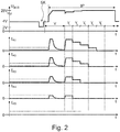
- N 5 sensor units S 1 , S 2 , ..., S N , each with a test resistor R S1 , R S2 , ..., R SN connected in series with the two-wire bus line 4, in each case one test load L 1 that can be connected to the two-wire bus line 4; L 2 , ...., L N and a previously mentioned address counter A 1 , A 2 , ..., A N Fig. 2 shown.
- Fig. 2 shows, depending on the time t, the curve of the bus voltage U Bus at the very top and below that the respective current I R1 , I R2 , I R3 , I R4 , I R5 through the test resistors R S1 , R S2 , ..., R SN .
- the address allocation process ie the address allocation phase IP, is initiated by means of a start command SK, during which the bus voltage is lowered from 4 V to 2 V for a period of 24 microseconds.
- a time delay V before the individual cycles Y 1 , Y 2 , Y 3 , Y 4 , Y 5 , in which the sensor units check their relative position in their chain to determine the influence to avoid any charging currents that may arise on the address assignment.
- the bus voltage U Bus is already increased to the address allocation voltage of 25 V or approximately 25 V; however, the test loads L 1 are not yet connected; L 2 , ...., L N with the two-wire bus line 4.
- the first cycle Y 1 of the address allocation phase IP then follows, in which all sensor units S 1 , S 2 ,..., S N connect their test loads L 1, L 2 ,..., L N to the two-wire bus line 4. Due to the test loads L 1; L 2 , ...., L N , which are located in the chain of sensor units S 1 , S 2 , ..., S N behind a respective sensor unit S 1 , S 2 , ..., S N-1 A current I R1 , I R2 , ..., I RN-1 flows through the test resistors R S1 , R S2 , ..., R SN- 1, which is greater, the more sensor units S 1 , S 2 , ..., S N are still arranged behind a respective sensor unit S 1 , S 2 , ..., S N-1.
- This last sensor unit S N receives the address 1 and no longer takes part in the further address allocation process. All other sensor units S 1 , S 2 , ..., S N-1 increase their address by 1.
- the test load of the sensor unit S N with the address 1 is permanently separated from the two-wire bus line 4 for the following cycles, so that insofar as that sensor unit S N-1 becomes the "last" sensor unit in the chain which is arranged immediately in front of the sensor unit S N with address 1.
- This process is repeated until all sensor units S 1 , S 2 , ..., S N are provided with an address, that is, the current I R1 has also become zero, since then sensor unit S 1 becomes the "last" sensor unit has become in the chain. Then the communication phases and energy supply phases can begin.
- the total test load L 1 , L 2 , ..., L N has always been activated directly; so the total maximum current always immediately flowed due to these test loads L 1 , L 2 , ...., L N.
- this can lead to the central unit Z becoming overloaded.
- FIG Fig. according to another preferred exemplary embodiment of the invention, as in FIG Fig.
Landscapes
- Engineering & Computer Science (AREA)
- Computer Networks & Wireless Communication (AREA)
- Signal Processing (AREA)
- General Engineering & Computer Science (AREA)
- Theoretical Computer Science (AREA)
- Mechanical Engineering (AREA)
- Computer Hardware Design (AREA)
- Physics & Mathematics (AREA)
- General Physics & Mathematics (AREA)
- Arrangements For Transmission Of Measured Signals (AREA)
- Small-Scale Networks (AREA)
Claims (13)
- Procédé permettant de faire fonctionner un agencement de capteurs (2) dans un véhicule automobile (1) sur la base d'un protocole DSI en mode classe de fonction de puissance, dans lequel- l'agencement de capteurs (2) présente une unité centrale (3) comme maître et une pluralité d'unités de détection (S1,S2, ..., SN) comme esclaves commandés par le maître,- l'unité centrale (3) et les unités de détection (S1, S2, ..., SN) sont connectées en série les unes avec les autres au moyen d'une ligne de bus bifilaire (4),- les unités de détection (S1, S2, ..., SN) présentent respectivement une résistance d'essai (RS1, RS2, ..., RSN) connectée en série avec la ligne de bus bifilaire (4), une charge d'essai électrique (L1, L2, ..., LN) pouvant être reliée à la ligne de bus bifilaire et un compteur d'adresses (A1, A2, ..., AN), et- au moins trois phases de fonctionnement différentes sont prévues sous la forme de phases de communication d'une part et de phases d'alimentation en énergie d'autre part qui alternent entre elles, et d'une phase d'attribution d'adresse (IP) précédant les phases de communication et les phases d'alimentation en énergie,comprenant les étapes suivantes consistant à :- transmettre des informations entre l'unité centrale (Z) et les unités de détection (S1, S2, ..., SN) au moyen d'une tension inférieure prédéterminée (VLOW-PWR) et d'une tension supérieure prédéterminée (VHIGH_PWR) comme une tension de bus (UBus) respective dans les phases de communication,
- alimenter les unités de détection (S1, S2, ..., SN) en énergie électrique par l'unité centrale (Z) dans les phases d'alimentation en énergie, dans lesquelles une tension en circuit ouvert (VIDLE), qui est supérieure d'au moins 1 V à la tension supérieure (VHIGH_PWR), est appliquée en tant que tension de bus (UBus)- affecter une adresse respective aux unités de détection (S1, S2, ..., SN) individuelles dans la phase d'attribution d'adresse au moyen des étapes a) à f) suivantes consistant à :a) stocker une première adresse dans les compteurs d'adresses (A1, A2, ..., AN) de toutes les unités de détection (S1, S2, ..., SN), la première adresse étant identique pour toutes les unités de détection (S1, S2, ..., SN),b) appliquer en tant que tension de bus (UBus) une tension d'attribution d'adresse qui est supérieure d'au moins 1 V à la tension supérieure (VHIGH_PWR),c) relier les charges d'essai électriques (S1, S2, ..., SN) de toutes les unités de détection (S1, S2, ..., SN) à la ligne de bus bifilaire (4) de sorte que respectivement un courant d'essai (IL1, IL2, ... ILN) est consommé par les unités de détection (S1, S2, ..., SN),d) détecter le courant (IR1, IR2, ..., IR5) passant respectivement par les résistances d'essai (RS1, RS2, ..., RSN),e) déconnecter définitivement la charge d'essai électrique (L1, L2, ..., LN) de la ligne de bus bifilaire (4) dans l'unité de capteur (S1, S2, ..., SN) dans laquelle aucun courant (IR1, IR2, ..., IR5) passant par la résistance d'essai (RS1, RS2, ..., RSN) n'a été détecté, et incrémenter l'adresse respective d'une valeur identique prédéterminée pour toutes les unités de détection (S1, S2, ..., SN) dans les compteurs d'adresses (A1, A2, ..., AN-1) de toutes les autres unités de détection (S1, S2, ..., SN-1) dont la charge d'essai électrique (L1, L2, ..., LN-1) n'a pas encore été déconnectée définitivement de la ligne de bus bifilaire (4),f) répéter les étapes d) et e) pour toutes les unités de détection (S1, S2, ..., SN-1) dont la charge d'essai électrique (L1, L2, ..., LN-1) n'a pas encore été déconnectée définitivement de la ligne de bus bifilaire (4) jusqu'à ce que dans toutes les unités de détection (S1, S2, ..., SN) la charge d'essai électrique (L1, L2, ..., LN) ait été déconnectée définitivement de la ligne de bus bifilaire (4). - Procédé selon la revendication 1, dans lequel les unités de détection (S1, S2, ..., SN) sont respectivement des actionneurs ayant une charge d'actionneur respective et présentent respectivement une charge de communication pouvant être commutée sur la ligne de bus bifilaire (4) à des fins de communication, la charge d'actionneur respective étant supérieure à la charge de communication respective et les charges d'actionneur étant utilisées en tant que charges d'essai (L1, L2, ..., LN) .
- Procédé selon la revendication 1 ou 2, comprenant l'étape consistant à :- appliquer une tension d'attribution d'adresse en tant que tension de bus qui est supérieure d'au moins 1 V à la tension supérieure et est égale à au moins 50 % de la tension en circuit ouvert.
- Procédé selon la revendication 3, comprenant l'étape consistant à :- appliquer une tension d'attribution d'adresse en tant que tension de bus (UBus) qui correspond au moins temporairement à la tension en circuit ouvert (VIDLE).
- Procédé selon la revendication 3, comprenant l'étape consistant à :- appliquer une tension d'attribution d'adresse en tant que tension de bus (UBus) qui est au moins temporairement égale à 25 V.
- Procédé selon l'une quelconque des revendications précédentes, dans lequel pour l'étape d), à partir de la première itération de cette étape, il s'applique ce qui suit :
d) déconnecter la charge d'essai électrique (L1, L2, ..., LN) de la ligne de bus bifilaire (4) dans toutes les unités de détection (S1, S2, ..., SN-1) dont la charge d'essai électrique (L1, L2, ..., LN-1) n'a pas encore été coupée définitivement, et par la suite, reconnecter la charge d'essai électrique (L1, L2, ..., LN-1) à la ligne de bus bifilaire (4) dans toute les unités de détection (S1, S2, ..., SN-1) dont la charge d'essai (L1, L2, ..., LN-1) n'a pas encore été déconnectée définitivement de la ligne de bus bifilaire (4) de sorte que respectivement un courant d'essai (IL1, IL2, ..., ILN-1) est consommé par ces unités de détection (S1, S2, ..., SN-1), et détecter le courant passant respectivement par les résistances d'essai (RS1, RS2, ..., RSN-1) de ces unités de détection (S1, S2, ..., SN-1). - Procédé selon la revendication 5, dans lequel la connexion des charges d'essai électriques (L1, L2, ..., LN) des unités de détection (S1, S2, ..., SN) à la ligne de bus bifilaire (4) dans les étapes c) et d) est effectuée par phases en au moins deux phases de telle sorte que dans la première phase, d'abord une partie de la charge d'essai (S1, S2, ..., SN) est activée, et ensuite, dans la ou les phases suivantes, la charge d'essai (L1, L2, ..., LN) est respectivement augmentée progressivement davantage.
- Procédé selon la revendication 6, dans lequel, dans les unités de détection (S1, S2, ..., SN), respectivement dans une phase suivante, aucune augmentation de la charge d'essai (L1, L2, ..., LN) n'est plus effectuée si dans la phase précédente un courant (IR1, IR2, ..., IR5) passant par la résistance d'essai (RS1, RS2, ..., RSN) de l'unité de détection (S1, S2, ..., SN) respective a été détecté qui a dépassé une valeur seuil prédéterminée (IT).
- Procédé selon l'une quelconque des revendications précédentes, dans lequel la première adresse est 1 et une incrémentation de 1 est effectuée lors des incrémentations d'adresses.
- Utilisation d'un procédé selon l'une quelconque des revendications précédentes dans un véhicule automobile (1).
- Support de stockage non volatile, lisible par ordinateur, comprenant des instructions stockées sur celui-ci qui provoquent un procédé selon l'une quelconque des revendications 1 à 9 lorsqu'elles sont exécutées dans un processeur.
- Agencement de capteurs, aménagé pour fonctionner au moyen d'un procédé selon l'une quelconque des revendications 1 à 9.
- Agencement de capteurs selon la revendication 12, présentant comme unités de détection (S1, S2, ..., SN) des unités de détection d'ultrasons destinées à émettre et/ou à recevoir des signaux ultrasonores.
Applications Claiming Priority (2)
| Application Number | Priority Date | Filing Date | Title |
|---|---|---|---|
| DE102017118567.4A DE102017118567A1 (de) | 2017-08-15 | 2017-08-15 | Verfahren zum Betreiben einer Sensoranordnung in einem Kraftfahrzeug auf Basis eines DSI-Protokolls |
| PCT/EP2018/071593 WO2019034511A1 (fr) | 2017-08-15 | 2018-08-09 | Procédé de fonctionnement d'un agencement de capteurs dans un véhicule automobile sur la base d'un protocole dsi |
Publications (2)
| Publication Number | Publication Date |
|---|---|
| EP3669500A1 EP3669500A1 (fr) | 2020-06-24 |
| EP3669500B1 true EP3669500B1 (fr) | 2021-05-05 |
Family
ID=63254678
Family Applications (1)
| Application Number | Title | Priority Date | Filing Date |
|---|---|---|---|
| EP18756170.9A Active EP3669500B1 (fr) | 2017-08-15 | 2018-08-09 | Procédé de fonctionnement d'un agencement de capteurs dans un véhicule automobile sur la base d'un protocole dsi |
Country Status (7)
| Country | Link |
|---|---|
| US (1) | US11349301B2 (fr) |
| EP (1) | EP3669500B1 (fr) |
| JP (1) | JP7083888B2 (fr) |
| KR (1) | KR102298187B1 (fr) |
| DE (1) | DE102017118567A1 (fr) |
| ES (1) | ES2877109T3 (fr) |
| WO (1) | WO2019034511A1 (fr) |
Families Citing this family (9)
| Publication number | Priority date | Publication date | Assignee | Title |
|---|---|---|---|---|
| DE102017118565A1 (de) * | 2017-08-15 | 2019-02-21 | Valeo Schalter Und Sensoren Gmbh | Verfahren zum Betreiben einer Sensoranordnung in einem Kraftfahrzeug auf Basis eines DSI-Protokolls |
| DE102018119533A1 (de) | 2018-08-10 | 2020-02-13 | Valeo Schalter Und Sensoren Gmbh | Verfahren und Vorrichtung zum Bereitstellen eines digitalen Sensorsignals eines Ultraschallsensors |
| JP7165882B2 (ja) * | 2019-03-14 | 2022-11-07 | パナソニックIpマネジメント株式会社 | 通信装置および通信システム |
| US11304344B2 (en) * | 2019-07-31 | 2022-04-12 | Hewlett Packard Enterprise Development Lp | Scalable universal sensor data acquisition with predictable timing |
| FI129883B (fi) * | 2020-03-04 | 2022-10-14 | Teknoware Oy | Menetelmiä ja järjestelyjä elektronisten laitteiden välisen tietoliikenteen järjestämiseksi liikennevälineessä |
| US11561601B2 (en) * | 2020-06-05 | 2023-01-24 | Apple Inc. | Method for performing system and power management over a serial data communication interface |
| US12052100B2 (en) * | 2021-02-01 | 2024-07-30 | Semiconductor Components Industries, Llc | DSI3 bus with enhanced robustness |
| DE102022209468A1 (de) | 2022-09-12 | 2024-03-14 | Robert Bosch Gesellschaft mit beschränkter Haftung | Ultraschallsystem für ein Fahrzeug und Fahrzeug |
| CN116155866B (zh) * | 2023-04-20 | 2023-06-20 | 中大智能科技股份有限公司 | 基于电流检测的阵列式位移计的地址自动分配方法和排序方法 |
Family Cites Families (13)
| Publication number | Priority date | Publication date | Assignee | Title |
|---|---|---|---|---|
| JPH0746258A (ja) * | 1993-07-28 | 1995-02-14 | Matsushita Electric Works Ltd | アドレス設定方法 |
| WO2002069518A1 (fr) * | 2001-02-27 | 2002-09-06 | Sekisuijushi Co., Ltd. | Emetteur-recepteur electrique comportant deux conducteurs et procede correspondant |
| DE10147512B4 (de) * | 2001-09-26 | 2004-08-26 | Elmos Semiconductor Ag | Verfahren zur Adressierung der Teilnehmer eines Bussystems |
| US7746114B2 (en) * | 2007-11-14 | 2010-06-29 | Denso Corporation | Bus switch and electronic switch |
| DE102008000570A1 (de) | 2008-03-07 | 2009-09-10 | Robert Bosch Gmbh | Ultraschallbasiertes Fahrerassistenzsystem |
| US8193828B2 (en) * | 2008-07-31 | 2012-06-05 | Freescale Semiconductor, Inc. | Buffer apparatus, integrated circuit and method of reducing a portion of an oscillation of an output signal |
| JP4957813B2 (ja) * | 2010-01-26 | 2012-06-20 | 株式会社デンソー | 通信用スレーブ及び通信ネットワークシステム |
| JP5045797B2 (ja) * | 2010-02-24 | 2012-10-10 | 株式会社デンソー | 通信用スレーブ |
| DE102012103907A1 (de) | 2012-05-04 | 2013-11-07 | Continental Automotive Gmbh | Verfahren zum Betrieb einer Empfangseinheit eines mit zumindest einer Sendeeinheit verbundenen Kraftfahrzeugsteuergeräts |
| JP2014241575A (ja) | 2013-05-14 | 2014-12-25 | 株式会社デンソー | 通信システム |
| DE102013226376A1 (de) | 2013-12-18 | 2015-06-18 | Robert Bosch Gmbh | Verfahren zur Sensoranbindung |
| US10247705B2 (en) | 2014-10-01 | 2019-04-02 | Sensor Networks, Inc. | Asset-condition monitoring system |
| US9588155B2 (en) * | 2014-10-16 | 2017-03-07 | Freescale Semiconductor, Inc. | Current detection circuit with over-current protection |
-
2017
- 2017-08-15 DE DE102017118567.4A patent/DE102017118567A1/de not_active Withdrawn
-
2018
- 2018-08-09 US US16/638,288 patent/US11349301B2/en active Active
- 2018-08-09 KR KR1020207004302A patent/KR102298187B1/ko active IP Right Grant
- 2018-08-09 EP EP18756170.9A patent/EP3669500B1/fr active Active
- 2018-08-09 WO PCT/EP2018/071593 patent/WO2019034511A1/fr unknown
- 2018-08-09 ES ES18756170T patent/ES2877109T3/es active Active
- 2018-08-09 JP JP2020508584A patent/JP7083888B2/ja active Active
Also Published As
| Publication number | Publication date |
|---|---|
| KR20200026996A (ko) | 2020-03-11 |
| JP2020532179A (ja) | 2020-11-05 |
| DE102017118567A1 (de) | 2019-02-21 |
| WO2019034511A1 (fr) | 2019-02-21 |
| ES2877109T3 (es) | 2021-11-16 |
| EP3669500A1 (fr) | 2020-06-24 |
| US11349301B2 (en) | 2022-05-31 |
| US20200176976A1 (en) | 2020-06-04 |
| JP7083888B2 (ja) | 2022-06-13 |
| KR102298187B1 (ko) | 2021-09-07 |
Similar Documents
| Publication | Publication Date | Title |
|---|---|---|
| EP3669500B1 (fr) | Procédé de fonctionnement d'un agencement de capteurs dans un véhicule automobile sur la base d'un protocole dsi | |
| EP2948857B1 (fr) | Noeud de bus et système de bus ainsi que procédé d'identification des noeud de bus du système de bus | |
| EP3493481B1 (fr) | Procédé d'alimentation de flux d'adressage au moyen des n uds de bus d'un système de bus de données série et n uds de bus pour un tel système de bus de données | |
| EP1875674B1 (fr) | Procede et dispositifs pour la transmission de donnees sur une ligne de donnees entre un appareil de commande et au moins un appareil de traitement de donnees decentralise | |
| EP3496341B1 (fr) | Procédé de commande d'un système de base de données série et noeuds de bus pour un tel système de base de données | |
| DE19756564A1 (de) | Nachrichtennetz mit automatischer Knotenkonfiguration bei identischen Knoten | |
| EP0277321A1 (fr) | Circuit pour le contrôle continu de la qualité d'une batterie multicellulaire | |
| DE10030987A1 (de) | Verfahren zur Initialisierung eines Systems zur Steuerung/Regelung der Betriebsabläufe eines Kraftfahrzeugs und ein solches System | |
| DE10147512A1 (de) | Verfahren zur Adressierung der Teilnehmer eines Bussystems | |
| EP2917795B1 (fr) | Procédé d'identification de la position de montage relative des modules utilisés dans un système électronique modulaire | |
| EP3669527B1 (fr) | Procédé de fonctionnement d'un agencement de capteurs dans un véhicule automobile sur la base d'un protocole dsi | |
| EP2007077A1 (fr) | Procédé de détermination de la position d'appareils esclaves dans une commutation en série et appareil esclave pour des commutations en série | |
| EP3298730B1 (fr) | Système de bus et procédé d'attribution d'adresses à des abonnés d'un système de bus | |
| EP1979793B1 (fr) | Procédé et dispositif d'attribution d'adresses dans un système comportant plusieurs unités de générateur disposées de façon parallèle | |
| EP3154220A1 (fr) | Unite de couplage de bus et systeme de bus dote d'une unite de couplage de bus | |
| EP2437228B1 (fr) | Alarme, installation d'alarme et procédé de reconnaissance d'erreurs de lignes de transmission | |
| DE112012000546T5 (de) | Übertragungsleitungs-Adressüberlappungs-Detektionssystem und Unterstation-Endgerät, das in dem System verwendet wird | |
| EP4018603B1 (fr) | Procédé de détection de la position d'au moins un abonné d'un bus | |
| EP3573290B1 (fr) | Procédé de fonctionnement d'un dispositif capteur dans un véhicule automobile à base d'un protocole dsi | |
| EP3882723A1 (fr) | Procédé d'attribution d'adresses à des participants de bus | |
| DE10020142A1 (de) | Bussystem | |
| DE102017117225B3 (de) | Kommunikationssystem mit Bus und Codierleitung | |
| DE102016215717A1 (de) | Zuordnung einer Ladeeinheit zu einer Mehrzahl von Elektrofahrzeugen in einem Netzwerk | |
| EP3808038A1 (fr) | Procédé destiné à faire fonctionner un système de capteurs dans un véhicule automobile sur la base d'un protocole dsi | |
| DE102012009480A1 (de) | Verfahren und Steuereinheit zur automatischen Erkennung einer Baudrate |
Legal Events
| Date | Code | Title | Description |
|---|---|---|---|
| STAA | Information on the status of an ep patent application or granted ep patent |
Free format text: STATUS: UNKNOWN |
|
| STAA | Information on the status of an ep patent application or granted ep patent |
Free format text: STATUS: THE INTERNATIONAL PUBLICATION HAS BEEN MADE |
|
| PUAI | Public reference made under article 153(3) epc to a published international application that has entered the european phase |
Free format text: ORIGINAL CODE: 0009012 |
|
| STAA | Information on the status of an ep patent application or granted ep patent |
Free format text: STATUS: REQUEST FOR EXAMINATION WAS MADE |
|
| 17P | Request for examination filed |
Effective date: 20200130 |
|
| AK | Designated contracting states |
Kind code of ref document: A1 Designated state(s): AL AT BE BG CH CY CZ DE DK EE ES FI FR GB GR HR HU IE IS IT LI LT LU LV MC MK MT NL NO PL PT RO RS SE SI SK SM TR |
|
| AX | Request for extension of the european patent |
Extension state: BA ME |
|
| DAV | Request for validation of the european patent (deleted) | ||
| DAX | Request for extension of the european patent (deleted) | ||
| GRAP | Despatch of communication of intention to grant a patent |
Free format text: ORIGINAL CODE: EPIDOSNIGR1 |
|
| STAA | Information on the status of an ep patent application or granted ep patent |
Free format text: STATUS: GRANT OF PATENT IS INTENDED |
|
| INTG | Intention to grant announced |
Effective date: 20201201 |
|
| GRAS | Grant fee paid |
Free format text: ORIGINAL CODE: EPIDOSNIGR3 |
|
| GRAA | (expected) grant |
Free format text: ORIGINAL CODE: 0009210 |
|
| STAA | Information on the status of an ep patent application or granted ep patent |
Free format text: STATUS: THE PATENT HAS BEEN GRANTED |
|
| AK | Designated contracting states |
Kind code of ref document: B1 Designated state(s): AL AT BE BG CH CY CZ DE DK EE ES FI FR GB GR HR HU IE IS IT LI LT LU LV MC MK MT NL NO PL PT RO RS SE SI SK SM TR |
|
| REG | Reference to a national code |
Ref country code: GB Ref legal event code: FG4D Free format text: NOT ENGLISH |
|
| REG | Reference to a national code |
Ref country code: CH Ref legal event code: EP |
|
| REG | Reference to a national code |
Ref country code: AT Ref legal event code: REF Ref document number: 1391220 Country of ref document: AT Kind code of ref document: T Effective date: 20210515 |
|
| REG | Reference to a national code |
Ref country code: DE Ref legal event code: R096 Ref document number: 502018005181 Country of ref document: DE |
|
| REG | Reference to a national code |
Ref country code: IE Ref legal event code: FG4D Free format text: LANGUAGE OF EP DOCUMENT: GERMAN |
|
| REG | Reference to a national code |
Ref country code: SE Ref legal event code: TRGR |
|
| REG | Reference to a national code |
Ref country code: LT Ref legal event code: MG9D |
|
| PG25 | Lapsed in a contracting state [announced via postgrant information from national office to epo] |
Ref country code: BG Free format text: LAPSE BECAUSE OF FAILURE TO SUBMIT A TRANSLATION OF THE DESCRIPTION OR TO PAY THE FEE WITHIN THE PRESCRIBED TIME-LIMIT Effective date: 20210805 Ref country code: FI Free format text: LAPSE BECAUSE OF FAILURE TO SUBMIT A TRANSLATION OF THE DESCRIPTION OR TO PAY THE FEE WITHIN THE PRESCRIBED TIME-LIMIT Effective date: 20210505 Ref country code: LT Free format text: LAPSE BECAUSE OF FAILURE TO SUBMIT A TRANSLATION OF THE DESCRIPTION OR TO PAY THE FEE WITHIN THE PRESCRIBED TIME-LIMIT Effective date: 20210505 Ref country code: HR Free format text: LAPSE BECAUSE OF FAILURE TO SUBMIT A TRANSLATION OF THE DESCRIPTION OR TO PAY THE FEE WITHIN THE PRESCRIBED TIME-LIMIT Effective date: 20210505 |
|
| REG | Reference to a national code |
Ref country code: ES Ref legal event code: FG2A Ref document number: 2877109 Country of ref document: ES Kind code of ref document: T3 Effective date: 20211116 |
|
| PG25 | Lapsed in a contracting state [announced via postgrant information from national office to epo] |
Ref country code: LV Free format text: LAPSE BECAUSE OF FAILURE TO SUBMIT A TRANSLATION OF THE DESCRIPTION OR TO PAY THE FEE WITHIN THE PRESCRIBED TIME-LIMIT Effective date: 20210505 Ref country code: NO Free format text: LAPSE BECAUSE OF FAILURE TO SUBMIT A TRANSLATION OF THE DESCRIPTION OR TO PAY THE FEE WITHIN THE PRESCRIBED TIME-LIMIT Effective date: 20210805 Ref country code: PL Free format text: LAPSE BECAUSE OF FAILURE TO SUBMIT A TRANSLATION OF THE DESCRIPTION OR TO PAY THE FEE WITHIN THE PRESCRIBED TIME-LIMIT Effective date: 20210505 Ref country code: PT Free format text: LAPSE BECAUSE OF FAILURE TO SUBMIT A TRANSLATION OF THE DESCRIPTION OR TO PAY THE FEE WITHIN THE PRESCRIBED TIME-LIMIT Effective date: 20210906 Ref country code: RS Free format text: LAPSE BECAUSE OF FAILURE TO SUBMIT A TRANSLATION OF THE DESCRIPTION OR TO PAY THE FEE WITHIN THE PRESCRIBED TIME-LIMIT Effective date: 20210505 Ref country code: IS Free format text: LAPSE BECAUSE OF FAILURE TO SUBMIT A TRANSLATION OF THE DESCRIPTION OR TO PAY THE FEE WITHIN THE PRESCRIBED TIME-LIMIT Effective date: 20210905 Ref country code: GR Free format text: LAPSE BECAUSE OF FAILURE TO SUBMIT A TRANSLATION OF THE DESCRIPTION OR TO PAY THE FEE WITHIN THE PRESCRIBED TIME-LIMIT Effective date: 20210806 |
|
| REG | Reference to a national code |
Ref country code: NL Ref legal event code: MP Effective date: 20210505 |
|
| PG25 | Lapsed in a contracting state [announced via postgrant information from national office to epo] |
Ref country code: NL Free format text: LAPSE BECAUSE OF FAILURE TO SUBMIT A TRANSLATION OF THE DESCRIPTION OR TO PAY THE FEE WITHIN THE PRESCRIBED TIME-LIMIT Effective date: 20210505 |
|
| PG25 | Lapsed in a contracting state [announced via postgrant information from national office to epo] |
Ref country code: SM Free format text: LAPSE BECAUSE OF FAILURE TO SUBMIT A TRANSLATION OF THE DESCRIPTION OR TO PAY THE FEE WITHIN THE PRESCRIBED TIME-LIMIT Effective date: 20210505 Ref country code: RO Free format text: LAPSE BECAUSE OF FAILURE TO SUBMIT A TRANSLATION OF THE DESCRIPTION OR TO PAY THE FEE WITHIN THE PRESCRIBED TIME-LIMIT Effective date: 20210505 Ref country code: DK Free format text: LAPSE BECAUSE OF FAILURE TO SUBMIT A TRANSLATION OF THE DESCRIPTION OR TO PAY THE FEE WITHIN THE PRESCRIBED TIME-LIMIT Effective date: 20210505 Ref country code: CZ Free format text: LAPSE BECAUSE OF FAILURE TO SUBMIT A TRANSLATION OF THE DESCRIPTION OR TO PAY THE FEE WITHIN THE PRESCRIBED TIME-LIMIT Effective date: 20210505 Ref country code: EE Free format text: LAPSE BECAUSE OF FAILURE TO SUBMIT A TRANSLATION OF THE DESCRIPTION OR TO PAY THE FEE WITHIN THE PRESCRIBED TIME-LIMIT Effective date: 20210505 Ref country code: SK Free format text: LAPSE BECAUSE OF FAILURE TO SUBMIT A TRANSLATION OF THE DESCRIPTION OR TO PAY THE FEE WITHIN THE PRESCRIBED TIME-LIMIT Effective date: 20210505 |
|
| REG | Reference to a national code |
Ref country code: DE Ref legal event code: R097 Ref document number: 502018005181 Country of ref document: DE |
|
| PLBE | No opposition filed within time limit |
Free format text: ORIGINAL CODE: 0009261 |
|
| STAA | Information on the status of an ep patent application or granted ep patent |
Free format text: STATUS: NO OPPOSITION FILED WITHIN TIME LIMIT |
|
| REG | Reference to a national code |
Ref country code: CH Ref legal event code: PL |
|
| PG25 | Lapsed in a contracting state [announced via postgrant information from national office to epo] |
Ref country code: MC Free format text: LAPSE BECAUSE OF FAILURE TO SUBMIT A TRANSLATION OF THE DESCRIPTION OR TO PAY THE FEE WITHIN THE PRESCRIBED TIME-LIMIT Effective date: 20210505 |
|
| 26N | No opposition filed |
Effective date: 20220208 |
|
| REG | Reference to a national code |
Ref country code: BE Ref legal event code: MM Effective date: 20210831 |
|
| PG25 | Lapsed in a contracting state [announced via postgrant information from national office to epo] |
Ref country code: LI Free format text: LAPSE BECAUSE OF NON-PAYMENT OF DUE FEES Effective date: 20210831 Ref country code: CH Free format text: LAPSE BECAUSE OF NON-PAYMENT OF DUE FEES Effective date: 20210831 |
|
| PG25 | Lapsed in a contracting state [announced via postgrant information from national office to epo] |
Ref country code: IS Free format text: LAPSE BECAUSE OF FAILURE TO SUBMIT A TRANSLATION OF THE DESCRIPTION OR TO PAY THE FEE WITHIN THE PRESCRIBED TIME-LIMIT Effective date: 20210905 Ref country code: LU Free format text: LAPSE BECAUSE OF NON-PAYMENT OF DUE FEES Effective date: 20210809 Ref country code: AL Free format text: LAPSE BECAUSE OF FAILURE TO SUBMIT A TRANSLATION OF THE DESCRIPTION OR TO PAY THE FEE WITHIN THE PRESCRIBED TIME-LIMIT Effective date: 20210505 |
|
| PG25 | Lapsed in a contracting state [announced via postgrant information from national office to epo] |
Ref country code: IT Free format text: LAPSE BECAUSE OF FAILURE TO SUBMIT A TRANSLATION OF THE DESCRIPTION OR TO PAY THE FEE WITHIN THE PRESCRIBED TIME-LIMIT Effective date: 20210505 Ref country code: IE Free format text: LAPSE BECAUSE OF NON-PAYMENT OF DUE FEES Effective date: 20210809 Ref country code: BE Free format text: LAPSE BECAUSE OF NON-PAYMENT OF DUE FEES Effective date: 20210831 |
|
| PG25 | Lapsed in a contracting state [announced via postgrant information from national office to epo] |
Ref country code: CY Free format text: LAPSE BECAUSE OF FAILURE TO SUBMIT A TRANSLATION OF THE DESCRIPTION OR TO PAY THE FEE WITHIN THE PRESCRIBED TIME-LIMIT Effective date: 20210505 |
|
| P01 | Opt-out of the competence of the unified patent court (upc) registered |
Effective date: 20230528 |
|
| PG25 | Lapsed in a contracting state [announced via postgrant information from national office to epo] |
Ref country code: HU Free format text: LAPSE BECAUSE OF FAILURE TO SUBMIT A TRANSLATION OF THE DESCRIPTION OR TO PAY THE FEE WITHIN THE PRESCRIBED TIME-LIMIT; INVALID AB INITIO Effective date: 20180809 |
|
| PG25 | Lapsed in a contracting state [announced via postgrant information from national office to epo] |
Ref country code: MK Free format text: LAPSE BECAUSE OF FAILURE TO SUBMIT A TRANSLATION OF THE DESCRIPTION OR TO PAY THE FEE WITHIN THE PRESCRIBED TIME-LIMIT Effective date: 20210505 |
|
| PG25 | Lapsed in a contracting state [announced via postgrant information from national office to epo] |
Ref country code: TR Free format text: LAPSE BECAUSE OF FAILURE TO SUBMIT A TRANSLATION OF THE DESCRIPTION OR TO PAY THE FEE WITHIN THE PRESCRIBED TIME-LIMIT Effective date: 20210505 |
|
| PG25 | Lapsed in a contracting state [announced via postgrant information from national office to epo] |
Ref country code: MT Free format text: LAPSE BECAUSE OF FAILURE TO SUBMIT A TRANSLATION OF THE DESCRIPTION OR TO PAY THE FEE WITHIN THE PRESCRIBED TIME-LIMIT Effective date: 20210505 |
|
| PGFP | Annual fee paid to national office [announced via postgrant information from national office to epo] |
Ref country code: DE Payment date: 20240806 Year of fee payment: 7 |
|
| PGFP | Annual fee paid to national office [announced via postgrant information from national office to epo] |
Ref country code: GB Payment date: 20240823 Year of fee payment: 7 |
|
| REG | Reference to a national code |
Ref country code: AT Ref legal event code: MM01 Ref document number: 1391220 Country of ref document: AT Kind code of ref document: T Effective date: 20230809 |
|
| PGFP | Annual fee paid to national office [announced via postgrant information from national office to epo] |
Ref country code: FR Payment date: 20240829 Year of fee payment: 7 |
|
| PGFP | Annual fee paid to national office [announced via postgrant information from national office to epo] |
Ref country code: ES Payment date: 20240909 Year of fee payment: 7 |
|
| PG25 | Lapsed in a contracting state [announced via postgrant information from national office to epo] |
Ref country code: AT Free format text: LAPSE BECAUSE OF NON-PAYMENT OF DUE FEES Effective date: 20230809 |
|
| PGFP | Annual fee paid to national office [announced via postgrant information from national office to epo] |
Ref country code: SE Payment date: 20240814 Year of fee payment: 7 |