EP0277321A1 - Circuit pour le contrôle continu de la qualité d'une batterie multicellulaire - Google Patents
Circuit pour le contrôle continu de la qualité d'une batterie multicellulaire Download PDFInfo
- Publication number
- EP0277321A1 EP0277321A1 EP87118442A EP87118442A EP0277321A1 EP 0277321 A1 EP0277321 A1 EP 0277321A1 EP 87118442 A EP87118442 A EP 87118442A EP 87118442 A EP87118442 A EP 87118442A EP 0277321 A1 EP0277321 A1 EP 0277321A1
- Authority
- EP
- European Patent Office
- Prior art keywords
- circuit
- measuring
- line
- common
- measurement
- Prior art date
- Legal status (The legal status is an assumption and is not a legal conclusion. Google has not performed a legal analysis and makes no representation as to the accuracy of the status listed.)
- Withdrawn
Links
Images


Classifications
-
- G—PHYSICS
- G01—MEASURING; TESTING
- G01R—MEASURING ELECTRIC VARIABLES; MEASURING MAGNETIC VARIABLES
- G01R31/00—Arrangements for testing electric properties; Arrangements for locating electric faults; Arrangements for electrical testing characterised by what is being tested not provided for elsewhere
- G01R31/36—Arrangements for testing, measuring or monitoring the electrical condition of accumulators or electric batteries, e.g. capacity or state of charge [SoC]
- G01R31/396—Acquisition or processing of data for testing or for monitoring individual cells or groups of cells within a battery
-
- Y—GENERAL TAGGING OF NEW TECHNOLOGICAL DEVELOPMENTS; GENERAL TAGGING OF CROSS-SECTIONAL TECHNOLOGIES SPANNING OVER SEVERAL SECTIONS OF THE IPC; TECHNICAL SUBJECTS COVERED BY FORMER USPC CROSS-REFERENCE ART COLLECTIONS [XRACs] AND DIGESTS
- Y10—TECHNICAL SUBJECTS COVERED BY FORMER USPC
- Y10S—TECHNICAL SUBJECTS COVERED BY FORMER USPC CROSS-REFERENCE ART COLLECTIONS [XRACs] AND DIGESTS
- Y10S320/00—Electricity: battery or capacitor charging or discharging
- Y10S320/18—Indicator or display
Definitions
- the invention relates to a circuit according to the preamble of claim 1.
- the primary measure for this check is the comparison of the individual cell voltages or the comparison of the voltages of individual cell groups with one another and with stored reference values.
- the cell current can be evaluated instead or in addition for monitoring. A conclusion on the internal resistance of the cells is possible from both information, which allows significant statements about the condition of the cells. Furthermore, e.g. B. the temperature of the individual cells is of great importance for optimizing the charging process.
- Such circuits and methods are of importance, for example, for the development of batteries in order to optimize their service life, or for simple remote monitoring of the quality status of large battery systems of various uses, e.g. B. in emergency units, especially in the case of extremely stressed batteries, the behavior of the weakest cell should determine the treatment of the entire battery.
- the invention has for its object to design a circuit according to the preamble of claim 1 so that a reliable determination of the voltage and / or other continuously changing physical or chemical parameters such as current, temperature of each individual cell or of cell groups of multi-cell batteries and from this a simple and reliable ongoing check of the quality of a multi-cell battery is made possible.
- the laying of electrical lines should be kept to a minimum.
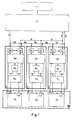
- a measuring circuit is connected to each of the cells 2a, 2b and 2c.
- the cell terminals are connected to a voltage adjustment 7a, 7b or 7c. From this voltage adjustment, two terminals lead to a power supply 6a, 6b and 6c. In parallel, there is a connection to transducers 3a, 3b and 3c.
- the output signals of these voltage adjustments are proportionally reduced values of the terminal voltages applied to these voltage adjustments. These voltage adjustments are only necessary for larger voltages, generally above 12 volts.
- the power supply 6a provides the power supply for the individual transducers 3a, 3b and 3c, or possibly for coupling elements 4a, 4b and 4c, which form the output of the transducers 3a, 3b and 3c, and optionally for Signal separation elements 5a, 5b and 5c, which are connected between the control line 9 coming from an evaluation circuit 10 and the transducers 3a, 3b and 3c.
- a power supply is necessary or not.
- the optocouplers that are preferably used do not require their own power supply as coupling elements.
- Start signals are supplied via a control line from a control, not shown, which is arranged within the evaluation circuit 10 in the exemplary embodiment according to FIG. 1 and is supplied to the signal separating elements 5a, 5b and 5c.
- this control signal is transmitted from one measuring circuit to the next measuring circuit, and from the last measuring circuit, the control line 9c is fed back to the control arranged within the evaluation circuit 10.
- the output signal of the signal separating element 5a of the first measuring circuit 1a triggers the measurement of the currently applied measured values within the transducer 3a, for example the applied battery voltage, the current currently drawn from the battery, the temperature inside the battery etc.
- the transducer 3a converts the measurement signals obtained into corresponding voltage pulses of a time duration which is proportional to the measured variable.
- the coupling element 4a causes the forwarding of this voltage pulse to the common measuring line 8 to the common evaluation circuit 10.
- the end flank of this voltage pulse is forwarded by the coupling element 4a via a partial control line 9a to the signal separating element 5b of the next measuring circuit 1b, where the measuring process is triggered in the same way .
- the end flank of the voltage pulse supplied by the corresponding coupling element 4b in turn controls the signal separating element 5c of the next measuring circuit 1c via a partial control line 9b and so on.
- control line sections 9d, 9e, 9f are also implemented, the measurement control signals are transmitted to the individual measuring circuits 1a, 1b, 1c via an address code assigned to each circuit.
- the evaluation circuit 10 supplies a signal which provides information about the current quality status of a battery. This signal can be passed on to a display device 11 and from there it can also be transmitted further.
- a battery B is shown with three individual cells 2a, 2b and 2c. Instead, any number of cells can be used. For example, 110 2V cells are required for a 220 volt battery.
- Figure 2 shows a schematic representation of an embodiment in which a two-wire measuring line 12 is provided, which is connected to each measuring circuit 14a, 14b, 14c via a measuring signal optocoupler 16a, 16b, 16c.
- the individual measurement signals are fed to the evaluation circuit in the form of a computer 15.
- the controller 15 is provided within the computer 15 and supplies an output trigger control pulse to the first measuring circuit 14a via a first control signal optocoupler 18 and via a first two-wire control line 13a To carry out the measurement of the measured values currently present at the associated first cell 2a and to pass them on to the common measuring line 12 via the first opto-coupler 16a.
- the measurement signal preferably consists of a pulse with a duration that is proportional to the measured value.
- the end edge of the measurement signal is used simultaneously to carry out the measurement of the associated second cell 2b via a first control signal opto-coupler 17a within the first measurement circuit 14a and a second control line 13b which is connected to the second measurement circuit 14b, and so on .
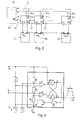
- FIG. 3 shows a circuit which can be used in the exemplary embodiment according to FIGS. 1 and 2 for converting the voltage U B present at the individual cells into a pulse with a duration proportional to U B.
- the voltage across the cell U B is applied via a first resistor R 1 to the positive connection of a first operational amplifier K 1, while the negative connection of this operational amplifier is connected to a constant current source with the same positive pole connected is.
- the plus terminal of a second operational amplifier K2 is connected to a trigger input Tr, while the minus terminal of this second operational amplifier K2 is connected via a second resistor R2 to the plus terminal of the first operational amplifier K1.
- the negative terminal of the second operational amplifier K2 is connected via a third resistor R3 to the emitter terminal of a transistor T.
- the collector terminal of the transistor T is connected to the negative terminal of the first operational amplifier K1.
- Both this connection and the plus connection of the first operational amplifier K 1 is via capacitors C and C 1 with Ground connected.
- the base of transistor T is connected via a resistor R4 to the output of a first inverting AND gate G1.
- a first input of the first inverting AND gate G1 is connected to the positive pole of the cell, a second input B of the first inverting AND gate is connected to the output of the first operational amplifier K1.
- the output of the first inverting AND gate G1 is connected to a first input C of a second inverting AND gate G2, while a second input D of the inverting AND gate G2 is connected to the output of the second operational amplifier K2.
- the output of the second inverting AND gate G2 supplies the desired output signal of the transducer in the form of a rectangular pulse U A , the duration T of which is proportional to the measured value U B applied to the transducer.
- FIG. 4 shows the circuit assignment of the measuring transducer 14 within the measuring circuit 1, the control trigger signal being fed from the control line 13a to the measuring transducer 14, the output signal of the measuring transducer 14 being supplied to the measuring signal optocoupler 16 in the form of the voltage pulse U A proportional to the measured value is, and wherein the end edge of this measurement signal is used to trigger the measurement process in the next cell by a control signal optocoupler 17, the measurement signal is supplied via a series resistor R5.
- the optocoupler 17 is connected via a second control line 13b to the measuring circuit or the measuring transducer of the next cell (not shown).
- the supply of the measurement start signal which is generated by a control within the computer or the transducer of the preceding cell (not shown), to the transducer (14) via a differentiator, consisting of mass resistance R E , capacitor C2, resistor R7 and Diode D1, which converts the end edge of the control pulse arriving via the control line 13a into a trigger pulse T.
- FIG. 5 shows an adaptation circuit according to FIG. 1, which serves to expand the measuring range in the event that several cells are connected to a single measuring circuit, with correspondingly higher measured values, in particular with regard to the battery voltage and the battery current.
- the core point of the matching circuit 7 according to FIG. 5 is an operational amplifier 0, the positive input + of which is connected to the terminal voltage of the battery via a fuse S and a first resistor R9, at the same time the positive connection is connected to ground via a second series resistor R8.
- the negative terminal of the operational amplifier 0 is connected to the output of the same, and thus the operational amplifier 0 represents a loadable voltage source U C which is proportional to the terminal voltage U B.
- the resistor R Z and the diode D Z serve to provide the supply voltage of the operational amplifier.
- the output of the operational amplifier 0 is connected as a voltage signal U C to the transducer 14 and supplies the output signal U A in the form of a rectangular pulse of certain duration which is proportional to the measured value.
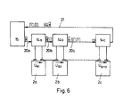
- FIG 6 shows the basic principle of the schematic overall measuring arrangement shown in Figure 2, wherein the same or corresponding parts are provided with the same reference numerals. The essential difference is the switching of the control line and the measuring line.
- the common evaluation circuit 15 in the form of a computer contains the common controller (not shown) and sends a start pulse to the first measuring circuit 14a via a first control line 20a to trigger the measurement on the first cell 2a. Both the measurement signal obtained and the control signal for triggering the measurement in the next cell 2b take place via a common combined second control and measurement line 20b to the second measurement circuit 14b and so on.
- the last measuring circuit 14c is connected via a common measuring line 21 to the evaluation circuit in the form of the Computer 15 connected. In this way, all measurements of a larger system can be carried out with a single line. This is particularly advantageous in the existing aggressive atmosphere.
- FIG. 7 shows an arrangement which corresponds in principle to that in FIG. 1 or, in terms of content, also to the arrangements according to FIG. 2 and FIG Evaluation circuit 10 goes out and leads back to this.
- the individual measuring circuits 1a, 1b and 1c are excited via the associated signal separating elements 5a, 5b, 5c to measure the associated cells.
- the measurement signal obtained is then routed successively to the common line via the opto-coupler 4a, 4b, 4c.
- the respective measurement signal simultaneously triggers the measurement of the next associated cell via the common line with line sections 22d, 22a, 22e, 22b, 22f and the associated signal separating element 5b, 5c.
- This special control signal for each measuring circuit can be generated, for example, directly in the control within the evaluation circuit 10, or as an output signal of the preceding coupling element 4a of the previously operated measuring circuit.
Landscapes
- Physics & Mathematics (AREA)
- General Physics & Mathematics (AREA)
- Measurement Of Current Or Voltage (AREA)
- Charge And Discharge Circuits For Batteries Or The Like (AREA)
- Secondary Cells (AREA)
Applications Claiming Priority (2)
| Application Number | Priority Date | Filing Date | Title |
|---|---|---|---|
| DE19873702591 DE3702591A1 (de) | 1987-01-29 | 1987-01-29 | Schaltung zur laufenden ueberpruefung der qualitaet einer mehrzelligen batterie |
| DE3702591 | 1987-01-29 |
Publications (1)
| Publication Number | Publication Date |
|---|---|
| EP0277321A1 true EP0277321A1 (fr) | 1988-08-10 |
Family
ID=6319762
Family Applications (1)
| Application Number | Title | Priority Date | Filing Date |
|---|---|---|---|
| EP87118442A Withdrawn EP0277321A1 (fr) | 1987-01-29 | 1987-12-12 | Circuit pour le contrôle continu de la qualité d'une batterie multicellulaire |
Country Status (4)
| Country | Link |
|---|---|
| US (1) | US4833459A (fr) |
| EP (1) | EP0277321A1 (fr) |
| DE (1) | DE3702591A1 (fr) |
| PT (1) | PT86618B (fr) |
Cited By (14)
| Publication number | Priority date | Publication date | Assignee | Title |
|---|---|---|---|---|
| FR2654553A1 (fr) * | 1989-11-14 | 1991-05-17 | Atlantique Technologies | Procede de gestion pour l'exploitation de batteries d'accumulateurs fixes ou embarquees et dispositif integre pour sa mise en óoeuvre. |
| WO1991017451A1 (fr) * | 1990-05-02 | 1991-11-14 | Alwyn Peter Ogborn | Controle de batteries |
| DE4132229A1 (de) * | 1991-09-27 | 1993-04-08 | Mentzer Electronic Gmbh | Einrichtung zur analyse und zur optimierung einer mehrzelligen batterie |
| EP0589287A2 (fr) * | 1992-09-22 | 1994-03-30 | MENTZER ELECTRONIC GmbH | Procédé pour le chargement d'une batterie multicellulaire |
| EP0643310A1 (fr) * | 1993-09-09 | 1995-03-15 | Regie Nationale Des Usines Renault S.A. | Dispositif de contrôle de la décharge d'une pluralité de batteries montées en série |
| EP0657745A1 (fr) | 1993-12-09 | 1995-06-14 | Saft | Circuit de mesure pour ensemble modulaire de cellules électriquement montées en série, notamment pour batterie d'accumulateur électrique |
| EP0678753A1 (fr) * | 1994-04-21 | 1995-10-25 | Saft | Circuit de mesure pour cellules électriques montées en série |
| DE19518729A1 (de) * | 1995-05-22 | 1996-11-28 | Mentzer Electronic Gmbh | Einrichtung zum Messen von Batteriezellparametern |
| US5652498A (en) * | 1995-02-07 | 1997-07-29 | Micro Compact Car Gmbh | Charge and discharge monitoring device for serially connected electric storage cells |
| EP0790690A3 (fr) * | 1996-02-14 | 1998-05-06 | Siemens Aktiengesellschaft | Module pour la détermination de l'état d'une batterie |
| FR2801982A1 (fr) * | 1999-12-06 | 2001-06-08 | Alain Leroy | Dispositif de controle d'une batterie d'accumulateurs et son procede associe |
| WO2006117270A2 (fr) * | 2005-05-04 | 2006-11-09 | Robert Bosch Gmbh | Accumulateur de charge et chargeur pour un accumulateur de charge |
| WO2008025478A1 (fr) * | 2006-08-30 | 2008-03-06 | Bayerische Motoren Werke Aktiengesellschaft | Accumulateur d'énergie avec tige de guidage |
| WO2014170360A1 (fr) * | 2013-04-18 | 2014-10-23 | Gerhard Kurz | Système de circuit permettant de mesurer des tensions individuelles d'éléments d'une batterie |
Families Citing this family (36)
| Publication number | Priority date | Publication date | Assignee | Title |
|---|---|---|---|---|
| US5339446A (en) * | 1986-12-26 | 1994-08-16 | Kabushiki Kaisha Toshiba | Power supply and method for use in a computer system to confirm a save operation of the computer system and to stop a supply of power to the computer system after confirmation |
| US5270946A (en) * | 1988-03-30 | 1993-12-14 | Kabushiki Kaisha Toshiba | Method and apparatus for controlling selection of batteries |
| US5132626A (en) * | 1989-05-31 | 1992-07-21 | Amoco Corporation | Electrolytic storage cell monitoring system |
| US5108369A (en) * | 1990-03-15 | 1992-04-28 | Diagnostic Devices Group, Limited | Dual-diameter multifunction catheter |
| NO174446C (no) * | 1991-03-12 | 1994-05-04 | Skand Instr As | Fremgangsmåte og anordning for overvåkning av elektrolytt-nivå i akkumulatorceller |
| US5214385A (en) * | 1991-05-22 | 1993-05-25 | Commonwealth Edison Company | Apparatus and method for utilizing polarization voltage to determine charge state of a battery |
| US5592069A (en) * | 1992-10-07 | 1997-01-07 | Dallas Semiconductor Corporation | Battery charger |
| DE4234231A1 (de) * | 1992-10-10 | 1994-04-14 | Wuerth Adolf Gmbh & Co Kg | Wiederaufladbarer Akku |
| DE4241523A1 (de) * | 1992-12-10 | 1994-06-16 | Edag Eng & Design Ag | Batterie-Überwachungsschaltung |
| AU691507B2 (en) * | 1993-09-17 | 1998-05-21 | Nec Corporation | Charging and discharging circuit for preventing overcharge and overdischarge of rechargable battery pack consisting of a plurality of rechargable batteries |
| DE4442825A1 (de) * | 1993-12-01 | 1995-06-08 | Aabh Patent Holdings | System zum Speichern elektrischer Energie |
| DE4408740C1 (de) * | 1994-03-15 | 1995-07-20 | Sonnenschein Accumulatoren | Schaltungsanordnung zur Überprüfung einer mehrzelligen Batterie |
| US5537042A (en) * | 1994-11-18 | 1996-07-16 | Eldec Corporation | Method and system for unobtrusively measuring physical properties in electrochemical processes |
| US5619417A (en) * | 1994-11-23 | 1997-04-08 | Chrysler Corporation | Battery monitoring system for an electric vehicle |
| US6184656B1 (en) | 1995-06-28 | 2001-02-06 | Aevt, Inc. | Radio frequency energy management system |
| US5703464A (en) * | 1995-06-28 | 1997-12-30 | Amerigon, Inc. | Radio frequency energy management system |
| US5712568A (en) * | 1995-09-05 | 1998-01-27 | Ford Motor Company | Battery voltage measurement system |
| DE19540671C2 (de) * | 1995-10-31 | 1997-08-07 | Oce Printing Systems Gmbh | Ferndiagnosevorrichtung zur Ferndiagnose für Spannungsversorgungseinrichtungen eines elektrografischen Druck- oder Kopiergerätes |
| DE19545833B4 (de) * | 1995-12-08 | 2005-10-13 | Bayerische Motoren Werke Ag | Batterie mit mehreren hintereinander geschalteten Einzelzellen |
| NO971841L (no) * | 1997-04-22 | 1998-10-23 | Einar Gotaas | Metode for driftsovervÕking av batterier |
| US5896024A (en) * | 1998-03-24 | 1999-04-20 | Black & Decker, Inc. | Method and apparatus for manually selecting battery charging process |
| JP3430083B2 (ja) * | 1999-10-21 | 2003-07-28 | 本田技研工業株式会社 | 電池電圧測定装置 |
| JP3656046B2 (ja) * | 2001-09-28 | 2005-06-02 | 長野日本無線株式会社 | 蓄電素子の電圧検出回路 |
| US6685334B2 (en) | 2002-04-30 | 2004-02-03 | G-5 Electronics | System and method of power management for a solar powered device |
| DE112004000227T5 (de) * | 2003-02-04 | 2006-01-19 | Hydrogenics Corp., Mississauga | System und Verfahren zum Messen eines inneren Widerstands elektrochemischer Vorrichtungen |
| JP4179205B2 (ja) * | 2004-03-29 | 2008-11-12 | サンケン電気株式会社 | 電圧測定装置 |
| CA2646925A1 (fr) * | 2007-12-12 | 2009-06-12 | Westward Industries Ltd. | Systeme de gestion de batteries |
| DE102008041518A1 (de) | 2008-08-25 | 2010-03-04 | Robert Bosch Gmbh | Akkumulatorüberwachungssystem |
| DE102008043921A1 (de) * | 2008-11-20 | 2010-05-27 | Robert Bosch Gmbh | Vorrichtung für elektrische Zellenspannungsmessungen |
| DE102010007076A1 (de) | 2010-02-06 | 2011-08-11 | Fraunhofer-Gesellschaft zur Förderung der angewandten Forschung e.V., 80686 | Elektrischer Energiespeicher |
| US8206862B2 (en) * | 2010-03-08 | 2012-06-26 | GM Global Technology Operations LLC | Method to measure and communicate cell voltage in a fuel cell stack by embedding measurement units on the plate |
| DE102010040031B4 (de) * | 2010-08-31 | 2019-01-03 | Continental Automotive Gmbh | Überwachung der Spannung einer Zelle eines Batterie-Energiespeichers auf ein Über- und/oder Unterschreiten einer Referenzspannung |
| JP5926143B2 (ja) * | 2012-07-18 | 2016-05-25 | ラピスセミコンダクタ株式会社 | 電池監視システム及び半導体装置 |
| DE102013225243A1 (de) * | 2013-12-09 | 2015-06-11 | Robert Bosch Gmbh | Verfahren zum Übertragen eines minimalen und/oder eines maximalen Wertes eines Batteriesystemparameters und Batteriesystem zur Ausführung eines solchen Verfahrens |
| DE102015002071A1 (de) | 2015-02-18 | 2016-08-18 | Audi Ag | Batteriezelle mit Überwachungsvorrichtung und zugehöriges Betriebsverfahren |
| US20180181181A1 (en) * | 2016-12-28 | 2018-06-28 | Hamilton Sundstrand Corporation | Differential current monitoring of multiple circuits |
Citations (4)
| Publication number | Priority date | Publication date | Assignee | Title |
|---|---|---|---|---|
| DE2842817B1 (de) * | 1978-09-30 | 1979-05-17 | Siemens Ag | Ermittlung des Ladezustandes einer Batterie |
| US4280097A (en) * | 1980-07-14 | 1981-07-21 | The United States Of America As Represented By The Secretary Of The Navy | Isolated DC voltage monitoring system |
| US4352067A (en) * | 1980-06-02 | 1982-09-28 | Dc Electronic Industries, Inc. | Battery analyzer |
| EP0112242A1 (fr) * | 1982-12-13 | 1984-06-27 | Electricite De France | Dispositif de contrôle de la capacité d'une batterie d'éléments d'accumulateur |
Family Cites Families (12)
| Publication number | Priority date | Publication date | Assignee | Title |
|---|---|---|---|---|
| US3786343A (en) * | 1973-03-19 | 1974-01-15 | Us Navy | Battery monitor system |
| DE2827479A1 (de) * | 1978-06-22 | 1980-01-17 | Reiner Szepan | Schaltung zum ueberwachen einzelner zellen oder zellengruppen einer kolonne von akkumulatorzellen |
| JPS5745757A (en) * | 1980-09-03 | 1982-03-15 | Hitachi Ltd | Ring type communication system of equal level |
| CH664637A5 (de) * | 1982-04-28 | 1988-03-15 | Cerberus Ag | Verfahren zur uebertragung von messwerten in einem ueberwachungssystem. |
| JPS5940739A (ja) * | 1982-08-30 | 1984-03-06 | Fujitsu Ltd | ル−プパツク制御方式 |
| US4495617A (en) * | 1982-09-09 | 1985-01-22 | A.B. Dick Company | Signal generation and synchronizing circuit for a decentralized ring network |
| JPS5963792U (ja) * | 1982-10-22 | 1984-04-26 | ニツタン株式会社 | 光電式煙検出端末機 |
| US4703451A (en) * | 1983-05-02 | 1987-10-27 | Calabrese Frank A | Data relay system |
| DE3337589A1 (de) * | 1983-10-15 | 1985-05-02 | Dornier System Gmbh | Verfahren und schaltung zur potentialfreien differenzmessung |
| US4581770A (en) * | 1983-12-19 | 1986-04-08 | Rca Corporation | Fail safe repeater for fiber optic bus distribution system |
| DE3412541A1 (de) * | 1984-04-04 | 1985-10-31 | Jungheinrich Unternehmensverwaltung Kg, 2000 Hamburg | Batterie-ladeanlage |
| US4725836A (en) * | 1986-01-27 | 1988-02-16 | Snap Systems, Inc. | Series port connection of a plurality of terminals to a master processor |
-
1987
- 1987-01-29 DE DE19873702591 patent/DE3702591A1/de active Granted
- 1987-12-12 EP EP87118442A patent/EP0277321A1/fr not_active Withdrawn
-
1988
- 1988-01-26 PT PT86618A patent/PT86618B/pt not_active IP Right Cessation
- 1988-01-27 US US07/148,890 patent/US4833459A/en not_active Expired - Fee Related
Patent Citations (4)
| Publication number | Priority date | Publication date | Assignee | Title |
|---|---|---|---|---|
| DE2842817B1 (de) * | 1978-09-30 | 1979-05-17 | Siemens Ag | Ermittlung des Ladezustandes einer Batterie |
| US4352067A (en) * | 1980-06-02 | 1982-09-28 | Dc Electronic Industries, Inc. | Battery analyzer |
| US4280097A (en) * | 1980-07-14 | 1981-07-21 | The United States Of America As Represented By The Secretary Of The Navy | Isolated DC voltage monitoring system |
| EP0112242A1 (fr) * | 1982-12-13 | 1984-06-27 | Electricite De France | Dispositif de contrôle de la capacité d'une batterie d'éléments d'accumulateur |
Cited By (25)
| Publication number | Priority date | Publication date | Assignee | Title |
|---|---|---|---|---|
| FR2654553A1 (fr) * | 1989-11-14 | 1991-05-17 | Atlantique Technologies | Procede de gestion pour l'exploitation de batteries d'accumulateurs fixes ou embarquees et dispositif integre pour sa mise en óoeuvre. |
| WO1991017451A1 (fr) * | 1990-05-02 | 1991-11-14 | Alwyn Peter Ogborn | Controle de batteries |
| DE4132229A1 (de) * | 1991-09-27 | 1993-04-08 | Mentzer Electronic Gmbh | Einrichtung zur analyse und zur optimierung einer mehrzelligen batterie |
| EP0589287A2 (fr) * | 1992-09-22 | 1994-03-30 | MENTZER ELECTRONIC GmbH | Procédé pour le chargement d'une batterie multicellulaire |
| EP0589287A3 (fr) * | 1992-09-22 | 1995-02-01 | Mentzer Electronic Gmbh | Procédé pour le chargement d'une batterie multicellulaire. |
| FR2709832A1 (fr) * | 1993-09-09 | 1995-03-17 | Renault | Dispositif de contrôle de la décharge d'une pluralité de batteries montées en série. |
| EP0643310A1 (fr) * | 1993-09-09 | 1995-03-15 | Regie Nationale Des Usines Renault S.A. | Dispositif de contrôle de la décharge d'une pluralité de batteries montées en série |
| EP0657745A1 (fr) | 1993-12-09 | 1995-06-14 | Saft | Circuit de mesure pour ensemble modulaire de cellules électriquement montées en série, notamment pour batterie d'accumulateur électrique |
| FR2713781A1 (fr) * | 1993-12-09 | 1995-06-16 | Accumulateurs Fixes | Circuit de mesure pour ensemble modulaire de cellules électriquement montées en série, notamment pour batterie d'accumulateur électrique. |
| US5578927A (en) * | 1993-12-09 | 1996-11-26 | Saft | Measurement circuit for a modular system of cells electrically connected in series, in particular for electrical accumlator batteries |
| EP0678753A1 (fr) * | 1994-04-21 | 1995-10-25 | Saft | Circuit de mesure pour cellules électriques montées en série |
| FR2719126A1 (fr) * | 1994-04-21 | 1995-10-27 | Accumulateurs Fixes | Circuit de mesure pour ensemble modulaire de cellules électriques raccordées en série, notamment pour ensemble de type batterie d'accumulateur. |
| US5638002A (en) * | 1994-04-21 | 1997-06-10 | Saft | Measurement circuit for a modular system of electrical cells connected in series, in particular for a system of the storage batterytype |
| US5652498A (en) * | 1995-02-07 | 1997-07-29 | Micro Compact Car Gmbh | Charge and discharge monitoring device for serially connected electric storage cells |
| DE19518729A1 (de) * | 1995-05-22 | 1996-11-28 | Mentzer Electronic Gmbh | Einrichtung zum Messen von Batteriezellparametern |
| US5754052A (en) * | 1995-05-22 | 1998-05-19 | Mentzer Electronic Gmbh | Device for measuring storage battery cell parameters |
| EP0790690A3 (fr) * | 1996-02-14 | 1998-05-06 | Siemens Aktiengesellschaft | Module pour la détermination de l'état d'une batterie |
| FR2801982A1 (fr) * | 1999-12-06 | 2001-06-08 | Alain Leroy | Dispositif de controle d'une batterie d'accumulateurs et son procede associe |
| WO2001042804A1 (fr) * | 1999-12-06 | 2001-06-14 | Alain Leroy | Procede de controle d'etat d'une batterie d'accumulateur |
| WO2006117270A2 (fr) * | 2005-05-04 | 2006-11-09 | Robert Bosch Gmbh | Accumulateur de charge et chargeur pour un accumulateur de charge |
| WO2006117270A3 (fr) * | 2005-05-04 | 2007-08-16 | Bosch Gmbh Robert | Accumulateur de charge et chargeur pour un accumulateur de charge |
| WO2008025478A1 (fr) * | 2006-08-30 | 2008-03-06 | Bayerische Motoren Werke Aktiengesellschaft | Accumulateur d'énergie avec tige de guidage |
| US8003246B2 (en) | 2006-08-30 | 2011-08-23 | Bayerische Motoren Werke Aktiengesellschaft | Energy store with guide rod |
| CN101501893B (zh) * | 2006-08-30 | 2012-01-11 | 宝马股份公司 | 具有引导杆的蓄能器 |
| WO2014170360A1 (fr) * | 2013-04-18 | 2014-10-23 | Gerhard Kurz | Système de circuit permettant de mesurer des tensions individuelles d'éléments d'une batterie |
Also Published As
| Publication number | Publication date |
|---|---|
| US4833459A (en) | 1989-05-23 |
| PT86618B (pt) | 1993-09-30 |
| DE3702591A1 (de) | 1988-08-11 |
| DE3702591C2 (fr) | 1991-03-28 |
| PT86618A (pt) | 1989-01-30 |
Similar Documents
| Publication | Publication Date | Title |
|---|---|---|
| EP0277321A1 (fr) | Circuit pour le contrôle continu de la qualité d'une batterie multicellulaire | |
| EP3669500B1 (fr) | Procédé de fonctionnement d'un agencement de capteurs dans un véhicule automobile sur la base d'un protocole dsi | |
| WO2009074193A1 (fr) | Dispositif et procédé pour générer une impulsion de charge donnée en vue de réaliser une mesure de décharge partielle | |
| DE112017000969T5 (de) | Vorrichtung zum Bestimmen der Verschlechterung von Sekundärbatterien | |
| DE19725710A1 (de) | Verfahren und Vorrichtung zur Leistungs- und Datenübermittlung auf gemeinsamen Leitungen | |
| EP2917795B1 (fr) | Procédé d'identification de la position de montage relative des modules utilisés dans un système électronique modulaire | |
| DE102011081147A1 (de) | Sensormodul zur Erfassung eines Betriebsparameters, Verfahren zur Überwachung eines Sensormoduls und Kombinationssignal | |
| WO1988007184A1 (fr) | Dispositif de mesure de forces de traction au moyen d'un dynamometre de traction | |
| CH660926A5 (de) | Ueberwachungsanlage. | |
| DE2545325B2 (de) | Schaltungsanordnung zur Messung des Isolationswiderstandes erdfreier Starkstromschaltungen | |
| EP0525350A2 (fr) | Procédé et dispositif pour tester des appareils de commande | |
| DE3622800A1 (de) | Messanordnung mit einer vielzahl von messeinheiten | |
| EP0204163B1 (fr) | Méthode de mesure pour la détermination de la qualité d'une batterie | |
| DE4328932C2 (de) | Verfahren und Einrichtung für die Fernabfrage von Meßstellen | |
| EP4238190A1 (fr) | Unité de distribution de courant comprenant une unité de détection de charge pour mesurer une tension de détection | |
| DE4231732C2 (de) | Verfahren zum Laden einer mehrzelligen Batterie | |
| EP3480609B1 (fr) | Modification des signaux de mesure d'essai pour dispositif de protection pour réseaux électriques | |
| EP3936875B1 (fr) | Circuit de mesure de la résistance, dispositif de mesure et procédé de mesure de la résistance | |
| DE1162427B (de) | Selbsttaetige Pruefeinrichtung fuer Fernmeldeleitungen, insbesondere in Fernsprechvermittlungsanlagen, zur Erfassung der an einer grossen Zahl von Leitungen auftretendengleichartigen elektrischen Groessen | |
| DE2752560C3 (de) | Verfahren zur Analog-Digital-Umsetzung von Spannungen nach dem Mehrfach-Integrationsprinzip und Schaltungsanordnung zur Durchführung des Verfahrens | |
| EP0122473A1 (fr) | Procédé de surveillance de la charge de batteries | |
| EP3082118A1 (fr) | Procede de transmission de donnees entre des dispositifs de mesure et un dispositif de traitement de donnees dans un systeme d'enregistrement de donnees de mesure | |
| DE102008057573A1 (de) | Kondensatoranordnung | |
| DE2518844C2 (de) | Schaltungsanordnung fuer die datenuebertragung von einer gemeinsamen zu einer mehrzahl ihr zugeordneter individueller einrichtungen in fernmeldeanlagen, insbesondere fernsprechvermittlungsanlagen | |
| DE102022100296A1 (de) | Verfahren und Vorrichtung zur Isolationsüberwachung von ungeerdeten Gleichspannungsnetzen |
Legal Events
| Date | Code | Title | Description |
|---|---|---|---|
| PUAI | Public reference made under article 153(3) epc to a published international application that has entered the european phase |
Free format text: ORIGINAL CODE: 0009012 |
|
| AK | Designated contracting states |
Kind code of ref document: A1 Designated state(s): AT BE ES FR GB |
|
| 17P | Request for examination filed |
Effective date: 19890329 |
|
| 17Q | First examination report despatched |
Effective date: 19911217 |
|
| STAA | Information on the status of an ep patent application or granted ep patent |
Free format text: STATUS: THE APPLICATION IS DEEMED TO BE WITHDRAWN |
|
| 18D | Application deemed to be withdrawn |
Effective date: 19931127 |