EP3668331B1 - Aerosolerzeugender artikel mit einem aerosolkühlelement - Google Patents
Aerosolerzeugender artikel mit einem aerosolkühlelement Download PDFInfo
- Publication number
- EP3668331B1 EP3668331B1 EP19701823.7A EP19701823A EP3668331B1 EP 3668331 B1 EP3668331 B1 EP 3668331B1 EP 19701823 A EP19701823 A EP 19701823A EP 3668331 B1 EP3668331 B1 EP 3668331B1
- Authority
- EP
- European Patent Office
- Prior art keywords
- aerosol
- cooling element
- wrapper material
- interior structure
- wrapper
- Prior art date
- Legal status (The legal status is an assumption and is not a legal conclusion. Google has not performed a legal analysis and makes no representation as to the accuracy of the status listed.)
- Active
Links
Images

Classifications
-
- A—HUMAN NECESSITIES
- A24—TOBACCO; CIGARS; CIGARETTES; SIMULATED SMOKING DEVICES; SMOKERS' REQUISITES
- A24D—CIGARS; CIGARETTES; TOBACCO SMOKE FILTERS; MOUTHPIECES OF CIGARS OR CIGARETTES; MANUFACTURE OF TOBACCO SMOKE FILTERS OR MOUTHPIECES
- A24D1/00—Cigars; Cigarettes
- A24D1/02—Cigars; Cigarettes with special covers
-
- A—HUMAN NECESSITIES
- A24—TOBACCO; CIGARS; CIGARETTES; SIMULATED SMOKING DEVICES; SMOKERS' REQUISITES
- A24D—CIGARS; CIGARETTES; TOBACCO SMOKE FILTERS; MOUTHPIECES OF CIGARS OR CIGARETTES; MANUFACTURE OF TOBACCO SMOKE FILTERS OR MOUTHPIECES
- A24D3/00—Tobacco smoke filters, e.g. filter tips or filtering inserts; Filters specially adapted for simulated smoking devices; Mouthpieces of cigars or cigarettes
- A24D3/02—Manufacture of tobacco smoke filters
-
- A—HUMAN NECESSITIES
- A24—TOBACCO; CIGARS; CIGARETTES; SIMULATED SMOKING DEVICES; SMOKERS' REQUISITES
- A24C—MACHINES FOR MAKING CIGARS OR CIGARETTES
- A24C5/00—Making cigarettes; Making tipping materials for, or attaching filters or mouthpieces to, cigars or cigarettes
- A24C5/005—Treatment of cigarette paper
-
- A—HUMAN NECESSITIES
- A24—TOBACCO; CIGARS; CIGARETTES; SIMULATED SMOKING DEVICES; SMOKERS' REQUISITES
- A24C—MACHINES FOR MAKING CIGARS OR CIGARETTES
- A24C5/00—Making cigarettes; Making tipping materials for, or attaching filters or mouthpieces to, cigars or cigarettes
- A24C5/01—Making cigarettes for simulated smoking devices
-
- A—HUMAN NECESSITIES
- A24—TOBACCO; CIGARS; CIGARETTES; SIMULATED SMOKING DEVICES; SMOKERS' REQUISITES
- A24C—MACHINES FOR MAKING CIGARS OR CIGARETTES
- A24C5/00—Making cigarettes; Making tipping materials for, or attaching filters or mouthpieces to, cigars or cigarettes
- A24C5/14—Machines of the continuous-rod type
- A24C5/18—Forming the rod
- A24C5/1885—Forming the rod for cigarettes with an axial air duct
-
- A—HUMAN NECESSITIES
- A24—TOBACCO; CIGARS; CIGARETTES; SIMULATED SMOKING DEVICES; SMOKERS' REQUISITES
- A24C—MACHINES FOR MAKING CIGARS OR CIGARETTES
- A24C5/00—Making cigarettes; Making tipping materials for, or attaching filters or mouthpieces to, cigars or cigarettes
- A24C5/14—Machines of the continuous-rod type
- A24C5/24—Pasting the seam
-
- A—HUMAN NECESSITIES
- A24—TOBACCO; CIGARS; CIGARETTES; SIMULATED SMOKING DEVICES; SMOKERS' REQUISITES
- A24D—CIGARS; CIGARETTES; TOBACCO SMOKE FILTERS; MOUTHPIECES OF CIGARS OR CIGARETTES; MANUFACTURE OF TOBACCO SMOKE FILTERS OR MOUTHPIECES
- A24D1/00—Cigars; Cigarettes
- A24D1/20—Cigarettes specially adapted for simulated smoking devices
-
- A—HUMAN NECESSITIES
- A24—TOBACCO; CIGARS; CIGARETTES; SIMULATED SMOKING DEVICES; SMOKERS' REQUISITES
- A24D—CIGARS; CIGARETTES; TOBACCO SMOKE FILTERS; MOUTHPIECES OF CIGARS OR CIGARETTES; MANUFACTURE OF TOBACCO SMOKE FILTERS OR MOUTHPIECES
- A24D3/00—Tobacco smoke filters, e.g. filter tips or filtering inserts; Filters specially adapted for simulated smoking devices; Mouthpieces of cigars or cigarettes
- A24D3/04—Tobacco smoke filters characterised by their shape or structure
-
- A—HUMAN NECESSITIES
- A24—TOBACCO; CIGARS; CIGARETTES; SIMULATED SMOKING DEVICES; SMOKERS' REQUISITES
- A24D—CIGARS; CIGARETTES; TOBACCO SMOKE FILTERS; MOUTHPIECES OF CIGARS OR CIGARETTES; MANUFACTURE OF TOBACCO SMOKE FILTERS OR MOUTHPIECES
- A24D3/00—Tobacco smoke filters, e.g. filter tips or filtering inserts; Filters specially adapted for simulated smoking devices; Mouthpieces of cigars or cigarettes
- A24D3/17—Filters specially adapted for simulated smoking devices
-
- B—PERFORMING OPERATIONS; TRANSPORTING
- B29—WORKING OF PLASTICS; WORKING OF SUBSTANCES IN A PLASTIC STATE IN GENERAL
- B29C—SHAPING OR JOINING OF PLASTICS; SHAPING OF MATERIAL IN A PLASTIC STATE, NOT OTHERWISE PROVIDED FOR; AFTER-TREATMENT OF THE SHAPED PRODUCTS, e.g. REPAIRING
- B29C65/00—Joining or sealing of preformed parts, e.g. welding of plastics materials; Apparatus therefor
- B29C65/02—Joining or sealing of preformed parts, e.g. welding of plastics materials; Apparatus therefor by heating, with or without pressure
- B29C65/08—Joining or sealing of preformed parts, e.g. welding of plastics materials; Apparatus therefor by heating, with or without pressure using ultrasonic vibrations
-
- B—PERFORMING OPERATIONS; TRANSPORTING
- B29—WORKING OF PLASTICS; WORKING OF SUBSTANCES IN A PLASTIC STATE IN GENERAL
- B29C—SHAPING OR JOINING OF PLASTICS; SHAPING OF MATERIAL IN A PLASTIC STATE, NOT OTHERWISE PROVIDED FOR; AFTER-TREATMENT OF THE SHAPED PRODUCTS, e.g. REPAIRING
- B29C65/00—Joining or sealing of preformed parts, e.g. welding of plastics materials; Apparatus therefor
- B29C65/02—Joining or sealing of preformed parts, e.g. welding of plastics materials; Apparatus therefor by heating, with or without pressure
- B29C65/34—Joining or sealing of preformed parts, e.g. welding of plastics materials; Apparatus therefor by heating, with or without pressure using heated elements which remain in the joint, e.g. "verlorenes Schweisselement"
- B29C65/36—Joining or sealing of preformed parts, e.g. welding of plastics materials; Apparatus therefor by heating, with or without pressure using heated elements which remain in the joint, e.g. "verlorenes Schweisselement" heated by induction
-
- B—PERFORMING OPERATIONS; TRANSPORTING
- B29—WORKING OF PLASTICS; WORKING OF SUBSTANCES IN A PLASTIC STATE IN GENERAL
- B29K—INDEXING SCHEME ASSOCIATED WITH SUBCLASSES B29B, B29C OR B29D, RELATING TO MOULDING MATERIALS OR TO MATERIALS FOR MOULDS, REINFORCEMENTS, FILLERS OR PREFORMED PARTS, e.g. INSERTS
- B29K2067/00—Use of polyesters or derivatives thereof, as moulding material
- B29K2067/04—Polyesters derived from hydroxycarboxylic acids
- B29K2067/046—PLA, i.e. polylactic acid or polylactide
-
- B—PERFORMING OPERATIONS; TRANSPORTING
- B29—WORKING OF PLASTICS; WORKING OF SUBSTANCES IN A PLASTIC STATE IN GENERAL
- B29K—INDEXING SCHEME ASSOCIATED WITH SUBCLASSES B29B, B29C OR B29D, RELATING TO MOULDING MATERIALS OR TO MATERIALS FOR MOULDS, REINFORCEMENTS, FILLERS OR PREFORMED PARTS, e.g. INSERTS
- B29K2667/00—Use of polyesters or derivatives thereof for preformed parts, e.g. for inserts
- B29K2667/04—Polyesters derived from hydroxycarboxylic acids
- B29K2667/046—PLA, i.e. polylactic acid or polylactide
-
- B—PERFORMING OPERATIONS; TRANSPORTING
- B29—WORKING OF PLASTICS; WORKING OF SUBSTANCES IN A PLASTIC STATE IN GENERAL
- B29L—INDEXING SCHEME ASSOCIATED WITH SUBCLASS B29C, RELATING TO PARTICULAR ARTICLES
- B29L2031/00—Other particular articles
- B29L2031/7414—Smokers'' requisites, e.g. pipe cleaners
- B29L2031/7416—Smokers'' requisites, e.g. pipe cleaners for cigars or cigarettes
Definitions
- the present invention relates to aerosol cooling elements for aerosol-generating articles and to methods of their manufacture.
- the present invention relates to aerosol-cooling elements comprising a wrapper material secured by welding.
- Aerosol-generating articles may comprise a plurality of elements assembled in the form of a rod. These elements may include an aerosol-forming substrate and an aerosol-cooling element located downstream from the aerosol-forming substrate.
- 'rod' is used to denote a generally cylindrical element of substantially circular, oval or elliptical cross-section.
- 'longitudinal direction' refers to a direction extending along, or parallel to, the cylindrical axis of a rod.
- upstream and downstream may be used to describe relative positions of elements or components of the aerosol-generating article.
- upstream and downstream refer to a relative position along the rod of the aerosol-generating article with reference to the direction in which the aerosol is drawn through the rod.
- the manufacture of aerosol-generating articles comprising aerosol-cooling elements may include forming raw material into a sheet.
- the sheet may then be crimped between two rollers to introduce parallel lines of weakness into the sheet.
- the crimped sheet may then be gathered into a rod by folding the sheet about the lines of weakness to form the rod with an internally pleated structure. This may be achieved by pulling the crimped sheet material through a funnel to compress the sheet into a continuous rod having a diameter approximately the diameter of the final tubular rod.
- the continuous rod may then be wrapped in a wrapper.
- the wrapper may be wrapping paper or other suitable wrapping material. For example, glue may be applied to one edge of the wrapper so that it can be wrapped around the continuous rod.
- the wrapped continuous rod may be compressed into a final desired shape while being heated to dry the applied glue.
- the wrapped continuous rod may then be cut into rods of smaller length to produce cooling elements of a desired length for use in aerosol-generating articles.
- the cooling elements described above have a large internal surface area that may provide enhanced thermal exchange between the cooling element and aerosol moving through it.
- the manufacture of aerosol-generating articles comprising aerosol-cooling elements can present several problems during production and in the finished article.
- One potential problem, which may be worsened by a high-mechanical resistance to compression of the sheet material, is that the glue may fail to hold the wrapper around the rod. This can lead to expansion of the wrapper over time and, thus, a failure in a control of a diameter of the rod.
- the wrapper seam may come apart completely. This can cause problems in later processes where a faulty rod may jam downstream equipment.
- the combiner which combines the elements of an aerosol-generating article and assembles them into the article can become jammed by unravelled or expanded aerosol-cooling elements.
- Another potential problem is glue pollution, where surplus glue from the seal may contaminate downstream equipment.
- US 2014/305448 discloses an aerosol-generating article including an aerosol-forming substrate; a support element located immediately downstream of the aerosol-forming substrate; an aerosol-cooling element located downstream of the support element; and an outer wrapper circumscribing the aerosol-forming substrate, the support element and the aerosol-cooling element.
- the support element abuts the aerosol-forming substrate.
- the aerosol-forming substrate is penetrable by a heating element of an aerosol-generating device.
- US 3437093 discloses a continuous-rod cigarette-making machine which produces a seam by joining the two edge portions of the paper by ultrasonic vibratory welding.
- an aerosol-cooling element for an aerosol-generating article as defined in claim 1 of the appended claims.
- C1/C2 is in a range from 1.3 to 4. In some embodiments, C1/C2 is in a range from 1.4 to 2.5.
- the average circumference is determined by measuring the average circumference of the cylindrical rod formed after the sheet material has been crimped and gathered.
- C1 is determined on a test bench by passing a sheet identical to that used on a production line through a funnel structure of the same dimensions as that used on the production line, without wrapping the gathered sheet.
- C1 is measured after the passing of a predetermined time of 2 minutes, after the sheet material has been gathered and folded. This is in order to allow the gathered and folded sheet material to settle into an uncompressed gathered state.
- C1 is then measured by way of a measuring tape passed around the cylindrical rod formed after the sheet material has been crimped and folded, taking care not to compress the cylindrical rod with the measuring tape while measuring C1.
- C2 is measured by measuring the circumference of the rod formed by the wrapper material secured around the interior structure in the same way as C1.
- the wrapper is welded around the interior structure, rather than by the application of glue, thereby addressing problems associated with a glued seam in the wrapper material.
- C2 is less than C1
- the interior structure is under compression by the wrapper. As such, the interior structure will tend to exert an outward force on the wrapper. Accordingly, using a known glued seam in the wrapper material would be problematic, because the outward force could cause the seam to come apart before the glue had set.
- This problem may be addressed by compressing the interior structure and the wrapper material when securing the wrapper material around the interior structure by welding the first portion of the wrapper material to the second portion of the wrapper material.
- welding may refer to any form of bonding or fusing, where heat is applied to cause a bond with the absence of an adhesive.
- welding may include at least partially melting a material.
- the term 'aerosol-generating article' refers to an article comprising an aerosol-forming substrate that is capable of releasing volatile compounds that can form an aerosol, for example by heating, combustion or a chemical reaction.
- the term 'aerosol-forming substrate' is used to describe a substrate capable of releasing volatile compounds, which can form an aerosol.
- the aerosols generated from aerosol-forming substrates of aerosol-generating articles according to the invention may be visible or invisible and may include vapours (for example, fine particles of substances, which are in a gaseous state, that are ordinarily liquid or solid at room temperature) as well as gases and liquid droplets of condensed vapours.
- the term 'aerosol-cooling element' is used to describe an element having a large surface area and a predetermined resistance to draw.
- an aerosol formed by volatile compounds released from the aerosol-forming substrate passes over and is cooled by the aerosol-cooling element before being inhaled by a user.
- aerosol-cooling elements In contrast to high resistance to draw filters and other mouthpieces, aerosol-cooling elements have a low resistance to draw. Chambers and cavities within an aerosol-generating article are also not considered to be aerosol cooling elements.
- 'sheet' and 'web' denote a laminar element having a width and length substantially greater than the thickness thereof.
- corrugated denotes a sheet or web with a plurality of corrugations, undulations or striations oriented in substantially the same direction.
- corrugations denotes a plurality of substantially parallel ridges formed from alternating peaks and troughs joined by corrugation flanks. This includes, but is not limited to, corrugations having a square wave profile, sinusoidal wave profile, triangular profile, sawtooth profile, or any combination thereof.
- the term 'crimped' denotes a sheet or web with a plurality of corrugations.
- the terms 'gathered' or 'gathering' denote that a web or sheet is convoluted, or otherwise compressed or constricted substantially transversely to the cylindrical axis of the rod.
- aspects of the invention do not require prior application of a glue to the wrapper material. Furthermore, welding may be achieved at a quicker rate than glue which may require curing or uniform application of pressure.
- the interior structure comprises a crimped and folded sheet material.
- this increases the surface area of the interior structure which may increase its cooling ability.
- the first portion of the wrapper material may be a region contiguous and parallel to a first edge of the wrapper material, and the second portion may be a region contiguous and parallel to a second edge of the wrapper material.
- this may provide a uniform, symmetric cooling element.
- the interior structure may comprise a longitudinal axis and the second edge of the wrapper material may be aligned at a non-zero angle to the longitudinal axis.
- the first portion may be welded to the second portion via a conductive element.
- the conductive element may comprise a metallic strip.
- the conductive element may be in contact with the first or second portion, or may be arranged between the first and second portions.
- the conductive element may conduct heat to the first and/or second portion to induce welding of the first portion to the second portion.
- this may increase ease and/or speed of the welding.
- the first portion may be induction welded to the second portion.
- Induction welding uses electromagnetic induction to heat a conductive element. This may provide a quick and optionally contactless process for welding the first portion to the second portion.
- the first portion may be ultrasonically welded to the second portion.
- Ultrasonic welding may use high frequency vibrations to weld one portion to another.
- the vibrations may be applied by a sonotrode for example.
- this may provide a quick method of welding that does not require the presence of a conductive element.
- the aerosol-cooling element may have a length between 7 mm and 28 mm, or optionally from 10 to 25 mm, or optionally from 13 to 22 mm, optionally from 16 to 19 mm.
- the aerosol-cooling element may have a diameter between 5 mm and 12 mm, optionally from 6 to 9 mm, or optionally from 7 to 8 mm.
- the wrapper material may comprise a thermoplastic polymer.
- a thermoplastic polymer may be readily welded to itself to provide a strong seal.
- polymeric materials can be formulated to have a melting point optimised for a particular welding process.
- the interior structure may comprise polylactic acid.
- the first portion and/or second portion of the wrapper may comprise an additional material that can be melted or heated to induce tack.
- the additional material may be in the form of one or more regions added to the wrapper, e.g. a thermoplastic strip added to the first portion and/or second portion of the wrapper.
- the additional material may allow welding of wrappers formed from material that cannot conventionally be welded, or may further improve the welding performance of a wrapper.
- an aerosol-generating article comprising any aerosol-cooling element in accordance with any aspect described herein.
- the aerosol-generating article may comprise an aerosol-forming substrate and the aerosol-cooling element may be located downstream of the aerosol-forming substrate.
- an aerosol-cooling element for an aerosol-generating article comprising:
- Providing the interior structure comprises forming a sheet material into a rod shape.
- Forming a sheet material into a rod shape comprises crimping the sheet material, and folding the sheet material. Folding the sheet material may comprise passing the sheet material through a funnel having an outlet diameter similar to that of the desired rod shape.
- the first portion of the wrapper material may be a region contiguous and parallel to a first edge of the wrapper material and the second portion may be a region contiguous and parallel to a second edge of the wrapper material.
- the interior structure may comprise a longitudinal axis; and wrapping the interior structure of the aerosol-cooling element may comprise placing the second edge in contact with the interior structure and at a non-zero angle to the longitudinal axis, and placing the first edge over the second edge.
- the method of manufacturing an aerosol-cooling element may further comprise placing a conductive element between the first portion and second portion of the wrapper material; and heating the conductive element to at least partially melt the first portion of the wrapper material.
- the conductive element may be placed in contact with one of the first portion or the second portion only, to weld one portion to the other.
- the method may comprise welding by induction welding. This may comprise inducing a current in a conductive element to melt a portion of the wrapper.
- the method may comprise welding by ultrasonic welding. Ultrasonic welding may comprise using a sonotrode to at least partially melt the wrapper material.
- the method of manufacturing an aerosol-cooling element may further comprise compressing the interior structure and wrapper material when securing the wrapper around the interior structure.
- a method for manufacturing an aerosol-generating article comprising manufacturing an aerosol-cooling element according to the foregoing aspects of the invention; and incorporating the aerosol-cooling element into the aerosol-generating article.
- the method may additionally comprise incorporating an aerosol-forming substrate in the aerosol-generating article, and incorporating the aerosol-cooling element downstream of the aerosol-forming substrate.
- an apparatus for manufacturing an aerosol-cooling element for an aerosol-generating article comprising:
- the present invention relates to an aerosol-cooling element for an aerosol-generating article.
- Aerosol-generating articles in which an aerosol-forming substrate, such as a tobacco containing substrate, is heated rather than combusted are known in the art.
- systems using aerosol-generating articles include systems that heat a tobacco containing substrate above 200 degrees Celsius to produce a nicotine-containing aerosol.
- the aerosol-cooling element may act to cool the temperature of a stream of aerosol drawn through the element by means of thermal transfer. Components of the aerosol will interact with the aerosol-cooling element and lose thermal energy.
- the aerosol-cooling element may act to cool the temperature of a stream of aerosol drawn through the element by undergoing a phase transformation that consumes heat energy from the aerosol stream.
- the material forming the aerosol-cooling element may undergo a phase transformation such as melting or a glass transition that requires the absorption of heat energy. If the element is selected such that it undergoes such an endothermic reaction at the temperature at which the aerosol enters the aerosol-cooling element, then the reaction will consume heat energy from the aerosol stream.
- the temperature of an aerosol stream may be lowered by more than 10 degrees Celsius as it is drawn through an aerosol-cooling element. In some embodiments, the temperature of an aerosol stream may be lowered by more than 15 degrees Celsius or more than 20 degrees Celsius as it is drawn through an aerosol-cooling element.
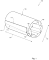
- FIG. 1 shows a schematic diagram of an aerosol-cooling element 100 for an aerosol-generating article according to an embodiment of the present invention.
- Aerosol-cooling element 100 comprises an interior structure 102 and a wrapper material 104 secured around the interior structure 102.
- the wrapper material 104 comprises a first portion 106 welded to a second portion 108 of the wrapper material 104.
- the interior structure 102 comprises a crimped, pleated or folded sheet material.
- the term 'crimped' denotes a sheet having a plurality of substantially parallel ridges or corrugations.
- the substantially parallel ridges or corrugations extend in a longitudinal direction with respect to the rod.
- the terms 'gathered', 'pleated', or 'folded' denote that a sheet of material is convoluted, folded, or otherwise compressed or constricted substantially transversely to the cylindrical axis of the rod.
- a sheet may be crimped prior to being gathered, pleated or folded.
- a sheet may be gathered, pleated or folded without prior crimping.
- the sheet material may comprise a sheet material selected from the group comprising a metallic foil, a polymeric sheet, and a substantially non-porous paper or cardboard.
- the aerosol-cooling element may comprise a sheet material selected from the group consisting of polyethylene (PE), polypropylene (PP), polyvinylchloride (PVC), polyethylene terephthalate (PET), polylactic acid (PLA), cellulose acetate (CA), and aluminium foil.
- the internal structure 102 fabricated from a crimped, pleated or folded material sheet increases the surface area of the internal structure and, thus, the ability of the internal structure 102 to cool aerosol passing through it.
- the internal structure 102 may be formed from a sheet material that has a specific surface area of between about 10 square millimetres per milligram (mm 2 /mg) and about 100 square millimetres per milligram (mm 2 /mg). In some embodiments, the specific surface area may be about 35 mm 2 /mg. Specific surface area can be determined by taking a material having a known width and thickness. For example, the material may be a polylactic acid material having an average thickness of 50 micrometres with a variation of ⁇ 2 micrometres. Where the material also has a known width, for example, between about 200 millimetres and about 250 millimetres, the specific surface area and density can be calculated.
- the first portion 106 of the wrapper material 104 is a region contiguous and parallel to a first edge 110 of the wrapper material 104 and the second portion 108 is a region contiguous and parallel to a second edge 112 of the wrapper material 104.
- the interior structure 102 has a longitudinal axis.
- the second edge 112 of the wrapper material 104 is aligned at a non-zero angle 116 to the longitudinal axis.
- the second edge 112 may be at an angle 116 (to the longitudinal axis) of about 20 degrees, 30 degrees or 40 degrees.
- the first portion 106 may be melt-bonded to the second portion 108 via a metallic strip (not shown). Alternatively, the first portion 106 may be induction welded to the second portion 108. The first portion 106 may be ultrasonically welded to the second portion 108.
- the aerosol-cooling element 100 may have a length 114 between 7 mm and 28 mm and may have a diameter 118 between 5 mm and 12 mm.
- the wrapper material 104 may comprise, or be made, from a polymer.
- the interior structure 102 comprises, or is made, from polylactic acid.
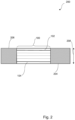
- FIG 2 shows a cross sectional diagram of an aerosol-generating article 200 comprising the aerosol-cooling element 100 of Figure 1 .
- the aerosol-generating article 200 further comprises an aerosol-forming substrate 204 and a filter 206.
- the aerosol-cooling element 100 is located downstream of the aerosol-forming substrate 204 and upstream of the filter 206.
- the elements of the aerosol-generating article 200 are preferably held together by means of a suitable wrapper, for example a tipping paper.
- the tipping paper may comprise any suitable material for wrapping components of the aerosol-generating article 200 in the form of a rod.
- the tipping paper needs to grip the component elements of the aerosol-generating article 200 when the article 200 is assembled and hold them in position within the rod. Suitable materials are well known in the art.
- the aerosol-generating article 200 may have a total length between approximately 30 mm and approximately 100 mm.
- the aerosol-generating article 200 may have an external diameter 208 between approximately 5 mm and approximately 12 mm.
- the filter 206 may be located at the downstream end of the aerosol-generating article 200.
- the filter 206 may be a cellulose acetate filter plug.
- the filter 206 may be approximately 7 mm in length in one embodiment, but may have a length of between approximately 5 mm and approximately 10 mm.
- the aerosol-generating article 200 may comprise a spacer element (not shown) located downstream of the aerosol-forming substrate 204. In one example, the aerosol-generating article 200 has a total length of approximately 45 mm.
- the aerosol-generating article 200 may have an external diameter 208 of approximately 7.2 mm.
- the aerosol-forming substrate 204 may have a length of approximately 10 mm. Alternatively, the aerosol-forming substrate 204 may have a length of approximately 12 mm. Further, the diameter of the aerosol-forming substrate 204 may be between approximately 5 mm and approximately 12 mm.
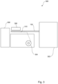
- FIG 3 shows a schematic diagram of an apparatus 300 for production of the aerosol-cooling elements 100 according to an embodiment of the present invention.
- Apparatus 300 comprises a crimping apparatus 302 which produces a continuous crimped internal structure 102, a material bobbin 304, which dispenses a layer of material around the continuous internal structure 102, a heat and press unit 306 and a cutting unit 308.
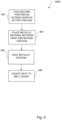
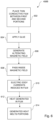
- Figure 4 shows a flow chart of a method 400 of manufacturing the aerosol-cooling elements 100 according to an embodiment of the present invention.
- the interior structure is provided 404 by crimping, pleating or folding 402 a sheet material into a continuous rod shaped interior structure 102.
- the interior structure 102 is wrapped 406 with a wrapper material 310.
- the wrapper material 310 is then secured 408 around the continuous interior structure 102 by welding a first portion 106 of the wrapper material 310 to a second portion 108 of the wrapper material 310.
- the first portion 106 of the wrapper material 310 is a region contiguous and parallel to a first edge 110 of the wrapper material 310 and the second portion 108 is a region contiguous and parallel to a second edge 112 of the wrapper material 310.
- the continuous interior structure 102 has a longitudinal axis. Wrapping 406 the continuous interior structure 102 comprises placing the second edge 112 in contact with the continuous interior structure 102 and at a non-zero angle 114 to the longitudinal axis, and placing the first edge 110 over the second edge 112.
- the continuous interior structure 102 and wrapper material 310 are compressed 410 to secure the wrapper material 310 around the continuous interior structure 102.
- the wrapped continuous interior structure 102 is then processed by the cutting unit 308 wherein it is cut 412 into the aerosol-cooling elements 100 of desired length 114, as shown in Figure 1 .
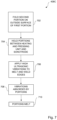
- Figure 5 shows a flow chart of a method 408A of securing the wrapper material 310 by melt-bonding according to an embodiment of the present invention.
- the second portion 108 is folded on an outside surface of the first portion 106.
- Heat from the heating and pressing unit 306 is adjusted to melt 508 the first and second portions 106, 108.
- the melted portions 106, 108 are then compressed 410.
- the continuous internal structure 102 can act as a backing block due to its resistance to compression.
- the wrapper material 310 is held and/or pressed by the heating and pressing unit 306 until the first and second portions 106, 108 have at least partially re-solidified.
- method 408A further comprises placing 504 a metallic material between the first portion 106 and second portion 108 of the wrapper material 310 and heating 506 the metallic material to at least partially melt the first portion 106 of the wrapper material 310.
- the shape of a heating part of the heating and pressing unit 306 may be concave with a diameter in the range of an average diameter of the aerosol-cooling element 100.
- the heating part may also be smooth so that the heated wrapper material 310 remains smooth and cylindrical.
- the heating and pressing unit 306 may have an outside coating made from a non-stick material to prevent any wrapper material 310 having too much friction resistance or grip on the heating part surface. This is especially likely when the wrapper material is in a molten state.
- the outside coating is made from polytetrafluoroethylene (PTFE) or a similar material.
- FIG. 6 shows a flow chart of an alternative method 408B of securing the wrapper material 310 using induction welding according to an embodiment of the present invention.
- the heating and pressing unit 306 comprises an induction heater.
- the induction heater comprises an electromagnet and an electronic oscillator that passes a high-frequency alternating current through the electromagnet.
- a thin conductive film is placed 602 between the first portion 106 and the second portion 108.
- the thin conductive film may be lightly glued 604 such that it stays in the correct position during the induction welding.
- An alternating current is passed through coils to generate 606 an alternating magnetic field.
- An area where the first portion 106, the conductive film and the second portion 108 are located is passed 608 inside the alternating magnetic field.
- the alternating magnetic field penetrates the film which induces 610 electric eddy currents in the film.
- the electric eddy currents flowing through the resistance of the film generate heat 612.
- the generated heat melts 614 the first portion 106 and the second portion 108 of the wrapper material 310.
- the melted first and second portions 106, 108 are then compressed 410 together by the heating and pressing unit 306 until they have at least partially re-solidified.
- Figure 7 shows a flow chart of another alternative method 408C of securing the wrapper material 310 using ultrasonic welding according to an embodiment of the present invention.
- the heating and pressing unit 306 comprises a sonotrode.
- Method 408C comprises folding 702 the second portion 108 on the outside surface of the first portion 106.
- the first and second portions are held 704 between the continuous internal structure 102 and/or heating and pressing unit and the sonotrode.
- the sonotrode is connected to a transducer such that high-frequency acoustic vibrations are emitted 706. Resulting vibrations are absorbed 708 by the first and second portions 106, 108 causing them to melt.
- the melted first portion 106 and second portion 108 are then compressed 410 until they have at least partially re-solidified.
- the wrapper material 310 may comprise or be made from a thermoplastic film such as a polylactic acid film.
- the continuous interior structure 102 may comprise or be made from a material resistant to compression such as polylactic acid.
- a method for manufacturing the aerosol-generating article 200 may comprise incorporating an aerosol-forming substrate 204, a filter 206 and the aerosol-cooling element 100 into a rod, wherein the aerosol-cooling element 100 is incorporated downstream of the aerosol-forming substrate 206.
- the filter 206 is a conventional mouthpiece filter formed from cellulose acetate.
- the filter 206 may have a length of about 45 millimetres.
- Heat from the welding methods 408A, 408B and 408C could alter an outside surface of the aerosol-cooling element 100.
- the outside surface of the aerosol-cooling element 100 may be covered by at least one tipping paper in the final aerosol-generating article 200. This tipping paper is usually used to hold elements of the aerosol-generating article 200 together. Thus, any slight alterations or imperfections of the outside surface of the aerosol-cooling element 100 need not be visible in the final aerosol-generating article 200.
- the aerosol-cooling element 100 may act to cool the temperature of a stream of aerosol drawn through the element by means of thermal transfer. Components of the aerosol will interact with the aerosol-cooling element 100 and lose thermal energy.
- the aerosol-cooling element 100 derived from method 400 with the method of securing 408 the wrapper material 310 by welding according to methods 408A, 408B or 408C has the advantage that the wrapper material 310 is held by welding of the wrapper material itself as opposed to being held by a glue. Replacing gluing with the stronger holding mechanism of welding alleviates issues with the gluing not being strong enough to hold the sheet material, which may be highly resistant to mechanical compression, in a cylinder.
- Another advantage of the present invention is that there is no need for substantially modification of existing equipment used in the manufacture of aerosol-generating articles. This has the effect that the method described herein of manufacturing aerosol-generating articles can be easily and cost effectively incorporated into current equipment and systems with only minor variations required. Processes wherein the equipment may not need to be modified to realise the method of manufacturing aerosol-generating articles as described herein include: equipment for the crimping process 302, equipment for the supplying the wrapper material 310, such as a bobbin, and equipment for cutting the rods 308. This has the advantage of keeping implementation costs low.
Landscapes
- Engineering & Computer Science (AREA)
- Mechanical Engineering (AREA)
- Containers And Packaging Bodies Having A Special Means To Remove Contents (AREA)
- Cigarettes, Filters, And Manufacturing Of Filters (AREA)
- Lining Or Joining Of Plastics Or The Like (AREA)
- Packages (AREA)
Claims (23)
- Aerosolkühlelement (100) für einen aerosolerzeugenden Artikel (200), das Aerosolkühlelement (100) umfassend:eine innere Struktur (102), die durch Wellen und Falten eines Blattmaterials gebildet wird, um einen zylindrischen Stock zu bilden, der zylindrische Stock aufweisend einen Umfang C1 in Abwesenheit beliebiger äußerer Druckkräfte; undein Umhüllungsmaterial (104), das um die innere Struktur (102) herum befestigt ist, um einen Stock mit einem Umfang C2 zu bilden;wobei das Umhüllungsmaterial (104) einen ersten Abschnitt (106) aufweist, der mit einem zweiten Abschnitt (108) des Umhüllungsmaterials (104) verschweißt ist;wobei die innere Struktur (102) durch das Umhüllungsmaterial (104) unter Druck steht, wenn das Umhüllungsmaterial (104) um die innere Struktur (102) befestigt ist;wobei C1/C2 in einem Bereich von 1,2 bis 6 liegt; undwobei C1 auf einem Prüfstand ermittelt wird, indem ein Prüfblatt, das mit dem bei Gebrauch auf einer Produktionslinie verwendeten identisch ist, durch eine Trichterstruktur mit denselben Abmessungen wie die auf der Produktionslinie verwendete geführt wird, um das Prüfblatt in Form eines zylindrischen Prüfstocks zusammenzufassen, das zusammengefasste Prüfblatt sich wenigstens für 2 Minuten in einen unkomprimierten, zusammengefassten Zustand absetzen darf, und Messen des Umfangs C1, indem ein Messband um den zylindrischen Prüfstock geführt wird, wobei darauf zu achten ist, dass der zylindrische Prüfstock während der Messung von C1 nicht mit dem Messband komprimiert wird.
- Aerosolkühlelement (100) nach Anspruch 1, wobei C1/C2 in einem Bereich von 1,3 bis 4, optional in einem Bereich von 1,4 bis 2,5 liegt.
- Aerosolkühlelement (100) nach Anspruch 1 oder Anspruch 2, wobei der erste Abschnitt (106) des Umhüllungsmaterials (104) ein Bereich ist, der an eine erste Kante (110) des Umhüllungsmaterials (104) angrenzt und zu dieser parallel ist, und wobei der zweite Abschnitt (108) ein Bereich ist, der an eine zweite Kante (112) des Umhüllungsmaterials (104) angrenzt und zu dieser parallel ist.
- Aerosolkühlelement (100) nach Anspruch 3, wobei die innere Struktur (102) eine Längsachse umfasst und die zweite Kante (112) des Umhüllungsmaterials (104) in einem von Null verschiedenen Winkel (116) zu der Längsachse ausgerichtet ist.
- Aerosolkühlelement (100) nach einem beliebigen vorhergehenden Anspruch, wobei der erste Abschnitt (106) mit dem zweiten Abschnitt (108) über einen Metallstreifen verschweißt ist.
- Aerosolkühlelement (100) nach Anspruch 5, wobei der erste Abschnitt (106) mit dem zweiten Abschnitt (108) induktionsgeschweißt ist.
- Aerosolkühlelement (100) nach einem beliebigen der Ansprüche 1 bis 4, wobei der erste Abschnitt (106) mit dem zweiten Abschnitt (108) ultraschallgeschweißt ist.
- Aerosolkühlelement (100) nach einem beliebigen vorhergehenden Anspruch, wobei das Aerosolkühlelement (100) eine Länge (114) zwischen 7 mm und 28 mm aufweist.
- Aerosolkühlelement (100) nach einem beliebigen vorhergehenden Anspruch, wobei das Aerosolkühlelement (100) einen Durchmesser (118) zwischen 5 mm und 12 mm aufweist.
- Aerosolkühlelement (100) nach einem beliebigen vorhergehenden Anspruch, wobei das Umhüllungsmaterial (104) ein Polymer umfasst, und optional, wobei die innere Struktur (102) Polymilchsäure umfasst.
- Aerosolerzeugender Artikel (200) in Form eines Stocks, der aerosolerzeugende Artikel (200) umfassend ein Aerosolkühlelement (100) nach einem beliebigen vorhergehenden Anspruch.
- Aerosolerzeugender Artikel (200) nach Anspruch 11, wobei der aerosolerzeugende Artikel (200) ein aerosolbildendes Substrat (204) umfasst und das Aerosolkühlelement (100) stromabwärts des aerosolbildenden Substrats (204) angeordnet ist.
- Verfahren zur Herstellung eines Aerosolkühlelements (100) für einen aerosolerzeugenden Artikel (200), das Verfahren umfassend:Vorsehen einer inneren Struktur (102) des Aerosolkühlelements (100) durch Wellen und Falten eines Blattmaterials in eine Stockform;Umhüllen der inneren Struktur (102) des Aerosolkühlelements (100) mit einem Umhüllungsmaterial (104);Befestigen des Umhüllungsmaterials (104) um die innere Struktur (102) durch Verschweißen eines ersten Abschnitts (106) des Umhüllungsmaterials (104) mit einem zweiten Abschnitt (108) des Umhüllungsmaterials (104); undKomprimieren der inneren Struktur (102) und des Umhüllungsmaterials (104) bei Befestigung des Umhüllungsmaterials (104) um die innere Struktur (102).
- Verfahren zur Herstellung eines Aerosolkühlelements (100) nach Anspruch 13, wobei der erste Abschnitt (106) des Umhüllungsmaterials (104) ein Bereich ist, der an eine erste Kante (110) des Umhüllungsmaterials (104) angrenzt und zu dieser parallel ist, und wobei der zweite Abschnitt (108) ein Bereich ist, der an eine zweite Kante (112) des Umhüllungsmaterials (104) angrenzt und zu dieser parallel ist.
- Verfahren zur Herstellung eines Aerosolkühlelements (100) nach Anspruch 14, wobei die innere Struktur (102) eine Längsachse umfasst; und wobei das Umhüllen der inneren Struktur (102) des Aerosolkühlelements (100) ein Anordnen der zweiten Kante (112) in Kontakt mit der inneren Struktur (102) und in einem von Null verschiedenen Winkel (116) zu der Längsachse und ein Anordnen der ersten Kante (110) über der zweiten Kante (112) umfasst.
- Verfahren zur Herstellung eines Aerosolkühlelements (100) nach Anspruch 13 oder 14, umfassend ein Anordnen eines leitfähigen Elements zwischen dem ersten Abschnitt (106) und dem zweiten Abschnitt (108) des Umhüllungsmaterials (104); und Erwärmen des leitfähigen Elements für ein Verschweißen des ersten Abschnitts (106) des Umhüllungsmaterials (104).
- Verfahren zur Herstellung eines Aerosolkühlelements (100) nach Anspruch 13 oder 14, wobei ein Verschweißen des ersten Abschnitts (106) des Umhüllungsmaterials (104) mit dem zweiten Abschnitt (108) des Umhüllungsmaterials (104) ein Induktionsschweißen umfasst.
- Verfahren zur Herstellung eines Aerosolkühlelements (100) nach Anspruch 13 oder 14, wobei ein Verschweißen des ersten Abschnitts (106) des Umhüllungsmaterials (104) mit dem zweiten Abschnitt (108) des Umhüllungsmaterials (104) ein Ultraschallschweißen umfasst.
- Verfahren zur Herstellung eines Aerosolkühlelements (100) nach Anspruch 18, wobei das Ultraschallschweißen ein Verwenden einer Sonotrode umfasst, um das Umhüllungsmaterial (104) wenigstens teilweise zu schmelzen.
- Verfahren zur Herstellung eines Aerosolkühlelements (100) nach einem beliebigen der Ansprüche 13 bis 19, wobei das Umhüllungsmaterial (104) ein Polymer umfasst und optional, wobei die innere Struktur (102) Polymilchsäure umfasst.
- Verfahren zur Herstellung eines aerosolerzeugenden Artikels (200), das Verfahren umfassend ein Herstellen eines Aerosolkühlelements (100) nach einem beliebigen der Ansprüche 13 bis 20; und Einarbeiten des Aerosolkühlelements (100) in den aerosolerzeugenden Artikel (200).
- Verfahren zur Herstellung eines aerosolerzeugenden Artikels (200) nach Anspruch 21, wobei der aerosolerzeugende Artikel (200) ein aerosolbildendes Substrat (204) umfasst und das Aerosolkühlelement (100) stromabwärts des aerosolbildenden Substrats (204) eingearbeitet ist.
- Vorrichtung (300) zur Herstellung eines Aerosolkühlelements (100) für einen aerosolerzeugenden Artikel (200), die Vorrichtung (300) umfassend:eine Zusammenführungseinheit (302) für ein Zusammenführen und Falten eines Vorrats an gewelltem Blattmaterial zu einer stockförmigen inneren Struktur (102) für das Aerosolkühlelement (100) in Stockform;eine Umhüllungseinheit zum Umhüllen der inneren Struktur (102) um eine Längsachse der Stockform mit einem Umhüllungsmaterial (104) und zum Befestigen des Umhüllungsmaterials (104) um die innere Struktur (102) durch Verschweißen eines ersten Abschnitts (106) des Umhüllungsmaterials (104) mit einem zweiten Abschnitt (108) des Umhüllungsmaterials (104); undeine Komprimierungseinheit (306) zum Komprimieren der inneren Struktur (102) und des Umhüllungsmaterials (104) bei Befestigung des Umhüllungsmaterials (104) um die innere Struktur (102).
Applications Claiming Priority (2)
| Application Number | Priority Date | Filing Date | Title |
|---|---|---|---|
| EP18157001 | 2018-02-15 | ||
| PCT/EP2019/051672 WO2019158335A1 (en) | 2018-02-15 | 2019-01-23 | Aerosol-generating article comprising an aerosol-cooling element |
Publications (3)
| Publication Number | Publication Date |
|---|---|
| EP3668331A1 EP3668331A1 (de) | 2020-06-24 |
| EP3668331C0 EP3668331C0 (de) | 2025-06-04 |
| EP3668331B1 true EP3668331B1 (de) | 2025-06-04 |
Family
ID=61226504
Family Applications (1)
| Application Number | Title | Priority Date | Filing Date |
|---|---|---|---|
| EP19701823.7A Active EP3668331B1 (de) | 2018-02-15 | 2019-01-23 | Aerosolerzeugender artikel mit einem aerosolkühlelement |
Country Status (7)
| Country | Link |
|---|---|
| US (2) | US11350661B2 (de) |
| EP (1) | EP3668331B1 (de) |
| JP (1) | JP7317027B2 (de) |
| KR (1) | KR102815675B1 (de) |
| CN (1) | CN111629616B (de) |
| RU (1) | RU2764594C1 (de) |
| WO (1) | WO2019158335A1 (de) |
Families Citing this family (9)
| Publication number | Priority date | Publication date | Assignee | Title |
|---|---|---|---|---|
| CN107087811B (zh) * | 2017-05-26 | 2019-10-11 | 湖北中烟工业有限责任公司 | 具有降低烟气温度和防止嘴棒热塌陷的低温卷烟 |
| USD999440S1 (en) | 2019-10-17 | 2023-09-19 | Philip Morris Products S.A. | Aerosol generating device |
| CN113907446A (zh) * | 2020-07-07 | 2022-01-11 | 中国烟草总公司郑州烟草研究院 | 炭加热卷烟 |
| KR20230128036A (ko) * | 2020-12-25 | 2023-09-01 | 정저우 토바코 리서치 인스티튜트 오브 씨엔티씨 | 측벽이 관통된 가열 담배 제품 |
| KR102605499B1 (ko) * | 2021-03-25 | 2023-11-23 | 주식회사 케이티앤지 | 냉각 성능과 향 지속성이 증진된 에어로졸 발생 물품 및 그의 제조 방법 |
| KR102605498B1 (ko) * | 2021-03-25 | 2023-11-22 | 주식회사 케이티앤지 | 냉각 성능과 향 지속성이 증진된 에어로졸 발생 물품 및 그의 제조 방법 |
| CN117580470A (zh) * | 2021-07-01 | 2024-02-20 | 日本烟草产业株式会社 | 香味吸入物品 |
| KR20240094860A (ko) * | 2022-12-16 | 2024-06-25 | 주식회사 케이티앤지 | 에어로졸 생성 물품용 냉각 세그먼트 및 이를 포함하는 에어로졸 생성 물품 |
| WO2025150139A1 (ja) * | 2024-01-11 | 2025-07-17 | 日本たばこ産業株式会社 | 香味生成物品に用いるロッド、当該ロッドの製造機、及び当該ロッドの製造方法 |
Family Cites Families (21)
| Publication number | Priority date | Publication date | Assignee | Title |
|---|---|---|---|---|
| US2001079A (en) | 1931-03-04 | 1935-05-14 | Deere & Co | Cotton harvester |
| US2001709A (en) * | 1932-02-27 | 1935-05-21 | Davidson Glenn | Cigarette mouthpiece or the like |
| GB966532A (en) * | 1962-06-29 | 1964-08-12 | David Theodore Nelson William | Improvements in or relating to the manufacture of cigarettes |
| US4480644A (en) * | 1981-08-03 | 1984-11-06 | British-American Tobacco Company Limited | Manufacture of cigarettes |
| JPS59135879A (ja) * | 1983-01-26 | 1984-08-04 | 日本たばこ産業株式会社 | デュアル形たばこ用フィルタ− |
| US6612479B2 (en) * | 2001-10-10 | 2003-09-02 | Ford Global Technologies, Llc | Apparatus and method for joining layers of materials |
| US7354426B2 (en) * | 2003-09-12 | 2008-04-08 | B. Braun Medical Inc. | Flexible container with a flexible port and method for making the same |
| JP3125624U (ja) * | 2006-06-23 | 2006-09-28 | 株式会社西淀マーク製作所 | 健康促進シート |
| ITBO20070126A1 (it) * | 2007-02-27 | 2007-05-29 | Gd Spa | Macchina per la produzione e /o confezionamento di articoli da fumo. |
| GB201114956D0 (en) * | 2011-08-31 | 2011-10-12 | British American Tobacco Co | Methods and apparatuses for manufacture of smoking article filters |
| WO2013034652A1 (en) * | 2011-09-09 | 2013-03-14 | Philip Morris Products S.A. | Smoking article filter including polymeric insert |
| EP2570041A1 (de) * | 2011-09-15 | 2013-03-20 | British American Tobacco (Investments) Limited | Rauchartikel und Herstellung davon |
| AR089602A1 (es) * | 2011-12-30 | 2014-09-03 | Philip Morris Products Sa | Articulo generador de aerosoles para usar con un dispositivo generador de aerosoles |
| EP2625975A1 (de) * | 2012-02-13 | 2013-08-14 | Philip Morris Products S.A. | Aerosolerzeugender Artikel mit Aerosolkühlelement |
| EP2625974A1 (de) * | 2012-02-13 | 2013-08-14 | Philip Morris Products S.A. | Aerosolerzeugender Artikel mit einer geschmackserzeugenden Komponente |
| US9445828B2 (en) | 2012-07-05 | 2016-09-20 | Cognition Medical Corp. | Methods, devices, and systems for postconditioning with clot removal |
| GB201407642D0 (en) * | 2014-04-30 | 2014-06-11 | British American Tobacco Co | Aerosol-cooling element and arrangements for apparatus for heating a smokable material |
| EP3214959B1 (de) | 2014-11-03 | 2019-10-09 | Philip Morris Products S.a.s. | Verfahren und vorrichtung zur herstellung einer gekräuselten bahn |
| WO2016199577A1 (ja) * | 2015-06-10 | 2016-12-15 | 日本たばこ産業株式会社 | 棒状喫煙物品における巻紙の端部接合構造および棒状喫煙物品用フィルター |
| MX2018015122A (es) * | 2016-06-30 | 2019-04-15 | Philip Morris Products Sa | Articulo para fumar con envoltura transparente. |
| CN108433197A (zh) * | 2018-06-12 | 2018-08-24 | 普维思信(北京)科技有限公司 | 一种加热不燃烧香烟及其组件 |
-
2019
- 2019-01-23 EP EP19701823.7A patent/EP3668331B1/de active Active
- 2019-01-23 US US16/967,836 patent/US11350661B2/en active Active
- 2019-01-23 CN CN201980009679.1A patent/CN111629616B/zh active Active
- 2019-01-23 JP JP2020542103A patent/JP7317027B2/ja active Active
- 2019-01-23 RU RU2020127490A patent/RU2764594C1/ru active
- 2019-01-23 WO PCT/EP2019/051672 patent/WO2019158335A1/en not_active Ceased
- 2019-01-23 KR KR1020207022988A patent/KR102815675B1/ko active Active
-
2022
- 2022-05-10 US US17/740,440 patent/US12121052B2/en active Active
Also Published As
| Publication number | Publication date |
|---|---|
| CN111629616A (zh) | 2020-09-04 |
| JP2021514181A (ja) | 2021-06-10 |
| BR112020013503A2 (pt) | 2020-12-01 |
| EP3668331C0 (de) | 2025-06-04 |
| EP3668331A1 (de) | 2020-06-24 |
| US11350661B2 (en) | 2022-06-07 |
| KR20200119248A (ko) | 2020-10-19 |
| US12121052B2 (en) | 2024-10-22 |
| CN111629616B (zh) | 2024-05-17 |
| RU2764594C1 (ru) | 2022-01-18 |
| JP7317027B2 (ja) | 2023-07-28 |
| WO2019158335A1 (en) | 2019-08-22 |
| US20220256912A1 (en) | 2022-08-18 |
| KR102815675B1 (ko) | 2025-06-02 |
| US20210037878A1 (en) | 2021-02-11 |
Similar Documents
| Publication | Publication Date | Title |
|---|---|---|
| US12121052B2 (en) | Aerosol-generating article comprising an aerosol-cooling element | |
| CN112218548B (zh) | 气溶胶生成制品和用于形成气溶胶生成制品的设备 | |
| RU2565272C2 (ru) | Запечатанный корпус упаковки, способ и устройство для его производства | |
| TW202002812A (zh) | 氣溶膠產生物件及用於製造此氣溶膠產生物件的方法 | |
| KR20200083570A (ko) | 에어로졸화 가능한 구조체 | |
| CN104010532A (zh) | 纸管和使用该纸管的香味吸引具 | |
| KR20170081170A (ko) | 압착 웹을 제조하기 위한 방법 및 장치 | |
| US20220395017A1 (en) | Composite aerosol-generating material | |
| KR20170094132A (ko) | 실질적으로 평평한 연속 물질의 포장된 무한한 로드를 제조하기 위한 장치 및 방법 | |
| CN115279214B (zh) | 用于将连续幅材材料成形为条的方法和设备 | |
| KR20220143697A (ko) | 기본 중량을 갖는 브리징 요소를 구비하는 에어로졸 발생 물품 | |
| US20240122232A1 (en) | Aerosol Generating Device | |
| JP2023542484A (ja) | エアロゾル生成物品を製造する方法 | |
| BR112020013503B1 (pt) | Elemento de refrigeração de aerossol, artigo gerador de aerossol, método e aparelho para a fabricação de um elemento de refrigeração de aerossol para um artigo gerador de aerossol | |
| CN113423556A (zh) | 用于制造波纹网的方法和设备 | |
| RU2808158C1 (ru) | Способ и установка для формования непрерывного материала в виде полотна в стержень | |
| CN1027431C (zh) | 熔敷刀 | |
| JP7698040B2 (ja) | エアロゾル発生物品の製造方法 | |
| CN118905093A (zh) | 排烟管及其制造方法 | |
| JP2023159760A (ja) | フィルムおよびフィルムコンデンサ | |
| JPS6119363A (ja) | ラミネ−ト材の筒貼り装置 | |
| JPH10194213A (ja) | ソフトバッグの製造方法 | |
| HK1198380B (en) | Paper tube and flavor-suctioning tool using same |
Legal Events
| Date | Code | Title | Description |
|---|---|---|---|
| STAA | Information on the status of an ep patent application or granted ep patent |
Free format text: STATUS: UNKNOWN |
|
| STAA | Information on the status of an ep patent application or granted ep patent |
Free format text: STATUS: THE INTERNATIONAL PUBLICATION HAS BEEN MADE |
|
| PUAI | Public reference made under article 153(3) epc to a published international application that has entered the european phase |
Free format text: ORIGINAL CODE: 0009012 |
|
| STAA | Information on the status of an ep patent application or granted ep patent |
Free format text: STATUS: REQUEST FOR EXAMINATION WAS MADE |
|
| 17P | Request for examination filed |
Effective date: 20200319 |
|
| AK | Designated contracting states |
Kind code of ref document: A1 Designated state(s): AL AT BE BG CH CY CZ DE DK EE ES FI FR GB GR HR HU IE IS IT LI LT LU LV MC MK MT NL NO PL PT RO RS SE SI SK SM TR |
|
| AX | Request for extension of the european patent |
Extension state: BA ME |
|
| DAV | Request for validation of the european patent (deleted) | ||
| DAX | Request for extension of the european patent (deleted) | ||
| STAA | Information on the status of an ep patent application or granted ep patent |
Free format text: STATUS: EXAMINATION IS IN PROGRESS |
|
| RIC1 | Information provided on ipc code assigned before grant |
Ipc: A24D 1/20 20200101ALN20220214BHEP Ipc: A24D 3/04 20060101ALI20220214BHEP Ipc: A24D 1/02 20060101AFI20220214BHEP |
|
| 17Q | First examination report despatched |
Effective date: 20220317 |
|
| GRAP | Despatch of communication of intention to grant a patent |
Free format text: ORIGINAL CODE: EPIDOSNIGR1 |
|
| STAA | Information on the status of an ep patent application or granted ep patent |
Free format text: STATUS: GRANT OF PATENT IS INTENDED |
|
| RIC1 | Information provided on ipc code assigned before grant |
Ipc: A24D 1/20 20200101ALN20250116BHEP Ipc: A24D 3/04 20060101ALI20250116BHEP Ipc: A24D 1/02 20060101AFI20250116BHEP |
|
| INTG | Intention to grant announced |
Effective date: 20250203 |
|
| GRAS | Grant fee paid |
Free format text: ORIGINAL CODE: EPIDOSNIGR3 |
|
| GRAA | (expected) grant |
Free format text: ORIGINAL CODE: 0009210 |
|
| STAA | Information on the status of an ep patent application or granted ep patent |
Free format text: STATUS: THE PATENT HAS BEEN GRANTED |
|
| AK | Designated contracting states |
Kind code of ref document: B1 Designated state(s): AL AT BE BG CH CY CZ DE DK EE ES FI FR GB GR HR HU IE IS IT LI LT LU LV MC MK MT NL NO PL PT RO RS SE SI SK SM TR |
|
| REG | Reference to a national code |
Ref country code: GB Ref legal event code: FG4D |
|
| REG | Reference to a national code |
Ref country code: CH Ref legal event code: EP |
|
| REG | Reference to a national code |
Ref country code: IE Ref legal event code: FG4D |
|
| U01 | Request for unitary effect filed |
Effective date: 20250604 |
|
| U07 | Unitary effect registered |
Designated state(s): AT BE BG DE DK EE FI FR IT LT LU LV MT NL PT RO SE SI Effective date: 20250611 |
|
| PG25 | Lapsed in a contracting state [announced via postgrant information from national office to epo] |
Ref country code: ES Free format text: LAPSE BECAUSE OF FAILURE TO SUBMIT A TRANSLATION OF THE DESCRIPTION OR TO PAY THE FEE WITHIN THE PRESCRIBED TIME-LIMIT Effective date: 20250604 |
|
| PG25 | Lapsed in a contracting state [announced via postgrant information from national office to epo] |
Ref country code: GR Free format text: LAPSE BECAUSE OF FAILURE TO SUBMIT A TRANSLATION OF THE DESCRIPTION OR TO PAY THE FEE WITHIN THE PRESCRIBED TIME-LIMIT Effective date: 20250905 Ref country code: NO Free format text: LAPSE BECAUSE OF FAILURE TO SUBMIT A TRANSLATION OF THE DESCRIPTION OR TO PAY THE FEE WITHIN THE PRESCRIBED TIME-LIMIT Effective date: 20250904 |
|
| PG25 | Lapsed in a contracting state [announced via postgrant information from national office to epo] |
Ref country code: PL Free format text: LAPSE BECAUSE OF FAILURE TO SUBMIT A TRANSLATION OF THE DESCRIPTION OR TO PAY THE FEE WITHIN THE PRESCRIBED TIME-LIMIT Effective date: 20250604 |
|
| PG25 | Lapsed in a contracting state [announced via postgrant information from national office to epo] |
Ref country code: HR Free format text: LAPSE BECAUSE OF FAILURE TO SUBMIT A TRANSLATION OF THE DESCRIPTION OR TO PAY THE FEE WITHIN THE PRESCRIBED TIME-LIMIT Effective date: 20250604 |
|
| PG25 | Lapsed in a contracting state [announced via postgrant information from national office to epo] |
Ref country code: RS Free format text: LAPSE BECAUSE OF FAILURE TO SUBMIT A TRANSLATION OF THE DESCRIPTION OR TO PAY THE FEE WITHIN THE PRESCRIBED TIME-LIMIT Effective date: 20250904 |
|
| PG25 | Lapsed in a contracting state [announced via postgrant information from national office to epo] |
Ref country code: IS Free format text: LAPSE BECAUSE OF FAILURE TO SUBMIT A TRANSLATION OF THE DESCRIPTION OR TO PAY THE FEE WITHIN THE PRESCRIBED TIME-LIMIT Effective date: 20251004 |
|
| PG25 | Lapsed in a contracting state [announced via postgrant information from national office to epo] |
Ref country code: SM Free format text: LAPSE BECAUSE OF FAILURE TO SUBMIT A TRANSLATION OF THE DESCRIPTION OR TO PAY THE FEE WITHIN THE PRESCRIBED TIME-LIMIT Effective date: 20250604 |
|
| PG25 | Lapsed in a contracting state [announced via postgrant information from national office to epo] |
Ref country code: CZ Free format text: LAPSE BECAUSE OF FAILURE TO SUBMIT A TRANSLATION OF THE DESCRIPTION OR TO PAY THE FEE WITHIN THE PRESCRIBED TIME-LIMIT Effective date: 20250604 |
|
| PG25 | Lapsed in a contracting state [announced via postgrant information from national office to epo] |
Ref country code: SK Free format text: LAPSE BECAUSE OF FAILURE TO SUBMIT A TRANSLATION OF THE DESCRIPTION OR TO PAY THE FEE WITHIN THE PRESCRIBED TIME-LIMIT Effective date: 20250604 |
|
| REG | Reference to a national code |
Ref country code: CH Ref legal event code: U11 Free format text: ST27 STATUS EVENT CODE: U-0-0-U10-U11 (AS PROVIDED BY THE NATIONAL OFFICE) Effective date: 20260201 |
|
| U20 | Renewal fee for the european patent with unitary effect paid |
Year of fee payment: 8 Effective date: 20260129 |