EP3668119A1 - Fertigungsverfahren für eine hörvorrichtung und hörvorrichtung - Google Patents
Fertigungsverfahren für eine hörvorrichtung und hörvorrichtung Download PDFInfo
- Publication number
- EP3668119A1 EP3668119A1 EP19208973.8A EP19208973A EP3668119A1 EP 3668119 A1 EP3668119 A1 EP 3668119A1 EP 19208973 A EP19208973 A EP 19208973A EP 3668119 A1 EP3668119 A1 EP 3668119A1
- Authority
- EP
- European Patent Office
- Prior art keywords
- basic
- plastic
- microphone
- manufacturing
- module
- Prior art date
- Legal status (The legal status is an assumption and is not a legal conclusion. Google has not performed a legal analysis and makes no representation as to the accuracy of the status listed.)
- Granted
Links
Images



Classifications
-
- H—ELECTRICITY
- H04—ELECTRIC COMMUNICATION TECHNIQUE
- H04R—LOUDSPEAKERS, MICROPHONES, GRAMOPHONE PICK-UPS OR LIKE ACOUSTIC ELECTROMECHANICAL TRANSDUCERS; ELECTRIC HEARING AIDS; PUBLIC ADDRESS SYSTEMS
- H04R25/00—Electric hearing aids
- H04R25/65—Housing parts, e.g. shells, tips or moulds, or their manufacture
- H04R25/658—Manufacture of housing parts
-
- H—ELECTRICITY
- H04—ELECTRIC COMMUNICATION TECHNIQUE
- H04R—LOUDSPEAKERS, MICROPHONES, GRAMOPHONE PICK-UPS OR LIKE ACOUSTIC ELECTROMECHANICAL TRANSDUCERS; ELECTRIC HEARING AIDS; PUBLIC ADDRESS SYSTEMS
- H04R31/00—Apparatus or processes specially adapted for the manufacture of transducers or diaphragms therefor
-
- H—ELECTRICITY
- H04—ELECTRIC COMMUNICATION TECHNIQUE
- H04R—LOUDSPEAKERS, MICROPHONES, GRAMOPHONE PICK-UPS OR LIKE ACOUSTIC ELECTROMECHANICAL TRANSDUCERS; ELECTRIC HEARING AIDS; PUBLIC ADDRESS SYSTEMS
- H04R25/00—Electric hearing aids
- H04R25/60—Mounting or interconnection of hearing aid parts, e.g. inside tips, housings or to ossicles
- H04R25/602—Mounting or interconnection of hearing aid parts, e.g. inside tips, housings or to ossicles of batteries
-
- H—ELECTRICITY
- H04—ELECTRIC COMMUNICATION TECHNIQUE
- H04R—LOUDSPEAKERS, MICROPHONES, GRAMOPHONE PICK-UPS OR LIKE ACOUSTIC ELECTROMECHANICAL TRANSDUCERS; ELECTRIC HEARING AIDS; PUBLIC ADDRESS SYSTEMS
- H04R25/00—Electric hearing aids
- H04R25/60—Mounting or interconnection of hearing aid parts, e.g. inside tips, housings or to ossicles
- H04R25/609—Mounting or interconnection of hearing aid parts, e.g. inside tips, housings or to ossicles of circuitry
-
- H—ELECTRICITY
- H04—ELECTRIC COMMUNICATION TECHNIQUE
- H04R—LOUDSPEAKERS, MICROPHONES, GRAMOPHONE PICK-UPS OR LIKE ACOUSTIC ELECTROMECHANICAL TRANSDUCERS; ELECTRIC HEARING AIDS; PUBLIC ADDRESS SYSTEMS
- H04R25/00—Electric hearing aids
- H04R25/65—Housing parts, e.g. shells, tips or moulds, or their manufacture
- H04R25/652—Ear tips; Ear moulds
-
- H—ELECTRICITY
- H04—ELECTRIC COMMUNICATION TECHNIQUE
- H04R—LOUDSPEAKERS, MICROPHONES, GRAMOPHONE PICK-UPS OR LIKE ACOUSTIC ELECTROMECHANICAL TRANSDUCERS; ELECTRIC HEARING AIDS; PUBLIC ADDRESS SYSTEMS
- H04R31/00—Apparatus or processes specially adapted for the manufacture of transducers or diaphragms therefor
- H04R31/006—Interconnection of transducer parts
-
- H—ELECTRICITY
- H04—ELECTRIC COMMUNICATION TECHNIQUE
- H04R—LOUDSPEAKERS, MICROPHONES, GRAMOPHONE PICK-UPS OR LIKE ACOUSTIC ELECTROMECHANICAL TRANSDUCERS; ELECTRIC HEARING AIDS; PUBLIC ADDRESS SYSTEMS
- H04R2225/00—Details of deaf aids covered by H04R25/00, not provided for in any of its subgroups
- H04R2225/021—Behind the ear [BTE] hearing aids
Definitions
- the invention relates to a manufacturing method for a hearing device. Furthermore, the invention relates to a hearing device, preferably one that is manufactured by means of the manufacturing method.
- a hearing device is usually used to output acoustic signals to the ear of a wearer of this hearing device.
- a hearing device usually comprises an output transducer, which is usually designed as a loudspeaker (also referred to as a “receiver” or “receiver”).
- This output transducer is usually surrounded by a housing part of the hearing device, for example a housing shell or the like, in order to protect the output transducer from environmental influences and / or to allow the output transducer to be oriented as intended, for example in the auditory canal of the hearing device wearer.
- Such a hearing device can be, for example, a headset, headphones, so-called (in ear) wearables, hearables, tinnitus maskers or the like.
- hearing devices also serve to care for people with reduced hearing through (often wearer-specific) amplified and / or filtered acoustic signals in order to at least partially compensate for the present hearing loss.
- a hearing device is also referred to as a hearing aid or hearing aid for short.
- the hearing device usually also comprises an input transducer, usually in the form of a microphone for recording ambient noise, and a downstream signal processor (also: “controller”) for processing (filtering and / or amplifying) signals generated from the ambient noise and to output these processed signals to the output converter.
- the output transducer can also - depending on the type of hearing impairment - be designed as a bone conduction hearing aid or a cochlear implant for mechanical or electrical stimulation of the hearing of the wearer.
- BTE behind-the-ear hearing aids
- the output transducer can also be arranged in this housing (part) and in this case is connected to the ear canal of the wearer by means of a sound tube in the intended wearing state.
- the loudspeaker can also be arranged in a separate housing part (often referred to as an “earpiece”) and connected to the components arranged in the actual hearing device housing via a signal line.
- so-called in-the-ear hearing aids in short: "ITE" are used which have a housing which contains all or part of the electronic components and which is to be worn in the ear canal.
- hearing aids are increasingly being developed with housings that are as liquid-tight as possible. This is to prevent the penetration of, for example, sweat or water (for example, when swimming or showering, in the rain, etc.). Since energy sources, specifically batteries, have to be replaced frequently, sealing the corresponding openings in the housing of the hearing device requires a comparatively high outlay. For this reason, housings are also known which are formed from as few individual parts as possible.
- the object of the invention is to enable a hearing device with an improved housing.
- the manufacturing method according to the invention is used to manufacture a hearing device, which is preferably a hearing aid, briefly referred to as a "hearing aid".
- the hearing device according to the invention also has at least one signal processor and at least one microphone, in particular for recording airborne sound from the surroundings of a user of the hearing device.
- the signal processor and the at least one microphone are preassembled in a spatially fixed position to form an electronic basic module.
- the basic electronics module is then inserted into a plastic shaping tool (in short: “tool”) and positioned and held in the tool by means of at least one structural element of the basic electronics module, which is in contact with the surroundings in the intended final production state.
- the basic electronic module is preferably aligned with this structural element relative to the tool, preferably in the corresponding cavity of the tool (also referred to as "centering").
- plastic is introduced into the tool to form a preferably media-tight main housing for the basic electronics module.
- the basic electronics module is embedded in this plastic. A sound channel for the fluidic connection of the microphone to the surroundings is kept free.
- main housing is understood here and below in particular to mean that this housing, or this housing part, surrounds a large part of the construction volume occupied by the hearing device, preferably by the basic electronics module.
- the main housing is preferably replaced by a Injection step of the plastic and thus monolithic.
- the main housing is optionally formed by several injection steps, which, however, are carried out in terms of process technology in such a way that the different components of the main housing are integrally connected to one another.
- the electronic basic module is preferably also provided with further electronic components.
- analog-digital converters are connected between the respective microphone and the signal processor, components for voltage stabilization of a supply voltage from an energy source are provided, and conductor tracks for signal transmission between the individual components.
- the hearing device can advantageously also be designed to be comparatively compact, since no gaps need to be kept in a separately manufactured housing for mounting the basic electronics module. Furthermore, a comparatively high media tightness (in particular water tightness) can be made possible. Manufacturing time can also be saved. Furthermore, in particular in the event that the main housing is manufactured in just one injection step, manufacturing effort, in particular effort in the design and manufacture of the tool, can be saved, since the tool can be comparatively simple in construction and nevertheless an at least almost complete embedding of the basic electronics module , at least the components to be housed in each case is made possible in only one injection step.
- a microphone cover is connected to the basic electronics module in particular before the basic electronics module is embedded in the plastic.
- This microphone cover encloses the microphone in relation to the surroundings when the hearing device is in the intended finished state.
- the sound channel to be kept clear (already preformed) runs through the microphone cover.
- the microphone cover in particular, together with the basic electronics module, provides an insert (also as “Insert” denotes), so that the sound channel does not have to be shaped in the injection step when the main housing is being shaped.
- the microphone cover is preferably integrally bonded to the main housing by embedding it in the plastic and thus as media-tight as possible.
- the above-described microphone cover is used as the structural element for holding and positioning the basic electronic module in the tool.
- the microphone cover forms a type of end cap of the hearing device, under which at least the membrane of the or the respective microphone is exposed to the internal end of the (respective, correspondingly assigned) sound channel.
- the tool in particular its cavity, has a complementary trough into which the microphone cover is inserted in a suitable manner - while positioning the entire basic electronics module.
- the tool has at least one protruding pin which, when the basic electronics module is inserted with the microphone cover attached to it, dips into the sound channel, seals it against the ingress of plastic and holds the basic electronics module positioned in the cavity.
- charging contacts arranged on the basic electronics module for a rechargeable battery of the hearing device are used as a structural element for holding and positioning the basic electronics module in the tool - in addition or as an alternative to the microphone cover described above.
- the hearing device therefore includes charging contacts that are already arranged during assembly on the basic electronic module and are preferably fastened — for example soldered on — in such a way that they can serve as a holder for the basic electronic module (possibly in cooperation with the microphone cover).
- the charging contacts preferably have a central area which is surrounded by an edge in the manner of a ring. This edge is designed to protrude or set back from the central area in the direction of the surroundings.
- the charging contacts are therefore preferably convex or concave in cross section, see above that - in the convex variant - for inserting into a corresponding recess in the tool or - in the concave variant - for plugging onto a pin or the like that protrudes from the tool.
- the edge has both a holding function and a centering function.
- the charging contacts are preferably designed to be rotationally symmetrical.
- a rechargeable battery which is used to supply energy to at least the signal processor, is connected to the basic electronics module.
- This rechargeable battery is also electrically coupled to the signal processor.
- the rechargeable battery is preferably also coupled to the charging contacts described above - optionally indirectly via charging electronics.
- the rechargeable battery is also embedded in the plastic together with the basic electronics module (which preferably includes the charging electronics present in this case). This enables a high level of integration of the manufacturing process, in particular a self-contained assembly for the hearing device. This can save manufacturing costs and / or assembly costs.
- the plastic is introduced into the plastic molding tool by means of injection molding as a thermoplastic. This enables high throughput in series production and a comparatively high degree of design freedom for the main housing.
- the rechargeable battery is surrounded with a particularly thermally insulating insulation material, for example a film, a suitable gel or the like, before being embedded in the plastic.
- a particularly thermally insulating insulation material for example a film, a suitable gel or the like.
- a connection port (in particular a plug connection) is used as a structural element for holding and positioning the basic electronic module in the tool.
- the basic electronics module preferably has a cutout in which a corresponding plug for coupling the external loudspeaker can engage.
- a displaceably designed element also referred to as a "slide" of the tool expediently engages in this recess and is in contact with the basic electronic module in order to hold and position it.
- the signal processor and the at least one microphone and, if appropriate, the charging contacts are positioned and arranged relative to one another on a carrier part to form the basic electronic module.
- the carrier part is, for example, a component which takes on purely mechanical functions - for example a "frame” formed from a metal or a plastic - on which a printed circuit board (also referred to as a printed circuit board - "PCB”) is arranged , in particular a three-dimensionally shaped printed circuit board or a combination thereof.
- PCB printed circuit board
- assembly injection molding is used as the injection molding process, by means of which a detachable connection between the main housing and the microphone cover is made possible.
- incompatible plastics are used, which do not form an integral connection during embedding, or a suitable temperature control is selected in the tool, which prevents the microphone cover from being heated by the inflowing melt to such an extent that an integral connection is formed.
- the hearing device according to the invention in particular the hearing aid, comprises, in addition to the basic electronics module described above with the signal processor and the at least one microphone, which are mounted in a spatially fixed position relative to one another, also the main housing which is made in one piece from plastic and into which the basic electronic module is kept, keeping the sound channel free fluidic connection of the microphone with the environment is embedded.
- the hearing device according to the invention is manufactured according to the manufacturing method described above and therefore has corresponding advantages.
- “Material connection” or a “material connection” between at least two parts connected to one another is understood here and below in particular to mean that the parts connected to one another at their contact surfaces by material association or crosslinking (for example due to atomic or molecular binding forces) Effect of an additive are held together.
- Fig. 1 is a hearing device, referred to briefly as "hearing aid 1".
- the hearing aid 1 specifically forms a so-called “behind-the-ear hearing aid”.
- the hearing aid 1 therefore has a base body 2 which contains electronic components of the hearing aid 1 and which is to be worn behind the ear of a user of the hearing aid 1.
- the hearing device 1 has a receiver connection means 4, by means of which acoustic output signals of the hearing device 1 can be passed on to an ear, specifically in the auditory canal of the user of the hearing device 1.
- the earpiece connection means 4 is an earpiece connection cable of an external loudspeaker (not shown in more detail), which is arranged in the auditory canal of the user when the hearing aid 1 is in the intended wearing state.
- the earphone connection means 4 is designed to be reversibly connectable to the base body 2 and is in the intended state (compare Fig. 1 ) in a connection port 6 (described in more detail below, see Fig. 6 ) coupled to the base body 2.
- the base body 2 has a main housing 8, which is described in more detail below, and a microphone cover 10 which is produced separately from the main housing.
- the base body 2 has an electronics base module 12.
- This in turn has a support frame 14 which is formed by a pre-bent and punched sheet metal strip 16 with molded plastic end pieces 18 (see. Fig. 2 ).
- the basic electronics module 12 has a pre-bent circuit board 20 equipped with electronic components, specifically formed by a three-dimensionally shaped printed circuit board.
- the electronics basic module 12 and thus also the hearing aid 1 comprise a signal processor 22, a number of further electronic components 24 (e.g. transistors, transducers and the like) as well as charging electronics 26 for a rechargeable battery 28 also arranged on the electronic basic module 12
- Basic electronics module 12 two microphones 30 - here designed as MEMS components. These two microphones 30 are arranged on a first end 32 of the basic electronic module 12 or of the hearing device 1.
- At a second end 34 of the basic electronic module 12 opposite the first end 32 - in the area of which the charging electronics 26 are arranged - a plurality, specifically four charging contacts 36 for charging the rechargeable battery 28 are arranged. These are connected to the battery 28 via the charging electronics 26.
- the microphone cover 10 forms an “end cap” arranged at the first end 32, which protects the microphones 30 from mechanical influences.
- an “end cap” arranged at the first end 32, which protects the microphones 30 from mechanical influences.
- two sound channels 38 are incorporated into the microphone cover 10.
- the basic electronics module 12 is shown in the intended assembly state.
- the basic electronics module 12 forms a pre-assembly unit of the hearing device 1.
- the circuit carrier 20 is plugged together with the carrier frame 14.
- the microphone cover 10 is also plugged onto the first end 32, specifically onto the end piece 18 there, or alternatively glued on.
- the basic electronics module 12 is inserted into a plastic molding tool, not specifically shown, specifically an injection molding tool, referred to for short as a tool.
- the basic electronics module 12 is then extrusion-coated with plastic to form the main housing 8, and thus embedded in this plastic.
- the sound channels 38 are kept open or free, ie not filled with plastic. Specifically, the microphone cover 10 is not covered with the injected plastic.
- Structural elements of the basic electronic module 12 are used for holding and positioning (also “centering") the basic electronic module 12 in the tool, specifically its cavity, in the manner described in more detail below.
- the microphone cover 10 is used as such a structural element.
- the basic electronics module 12 is inserted with the microphone cover 10 into a complementary recess in the cavity.
- the cutout is dimensioned in such a way that plastic is prevented from flowing around the microphone cover 10 in the injection molding process and, on the other hand, mechanical fixing of the basic electronics module 12 is made possible.
- Rigid or displaceable tool elements (so-called “slides”) optionally engage in the sound channels 38 for additional sealing and mounting.
- connection port 6 is used as the structural element for holding and positioning the basic electronic module 12.
- the connection port 6 has a recess formed in one of the end pieces 18, in or on which mechanical latching means for fixing the receiver connection means 4 and electrical connection contacts for contacting the receiver connection means (and thus the external loudspeaker) are arranged (not shown in more detail).
- an (optionally further) slide of the tool engages in the connection port 6 and thereby leads to a mounting, positioning and sealing of the connection contacts and locking elements of the connection port 6 against flow around with plastic.
- the microphone cover 10 As a structural element, a comparatively stable mounting and positioning of the basic electronics module 12 can be made possible together with the slide engaging in the connection port 6.
- each of the charging contacts 36 which are in the intended partial assembly state of the hearing device 1 (compare Fig. 6 ) exposed to the environment, used.
- each of the charging contacts 36 has a central area 40 which is surrounded by an edge 42 in a ring shape.
- the edge 42 is offset from the central region 40.
- the edge 42 protrudes from the central area 40 towards the surroundings.
- the edge 42 is set back relative to the central area 40 (consequently, the central area 40 projects towards the surroundings).
- the charging contacts 36 are plugged onto complementary pins of the tool, whereas the charging contacts 36 according to Fig. 8 be inserted into complementary recesses (holes) in the tool.
- both the charging contacts 36, the connection port 6 and the microphone cover 10 are used for positioning the holder.
- the rechargeable battery 28 is covered with an insulation film (not shown) for thermal insulation against the heat of the injected plastic before it is inserted into the tool, in particular when the electronics basic module 12 is being installed.
Landscapes
- Engineering & Computer Science (AREA)
- Physics & Mathematics (AREA)
- Acoustics & Sound (AREA)
- Signal Processing (AREA)
- Manufacturing & Machinery (AREA)
- Health & Medical Sciences (AREA)
- General Health & Medical Sciences (AREA)
- Neurosurgery (AREA)
- Otolaryngology (AREA)
- Electrostatic, Electromagnetic, Magneto- Strictive, And Variable-Resistance Transducers (AREA)
- Injection Moulding Of Plastics Or The Like (AREA)
Abstract
Description
- Die Erfindung betrifft ein Fertigungsverfahren für eine Hörvorrichtung. Des Weiteren betrifft die Erfindung eine Hörvorrichtung, vorzugsweise eine solche, die mittels des Fertigungsverfahrens hergestellt ist.
- Eine Hörvorrichtung dient üblicherweise zur Ausgabe von akustischen Signalen an das Ohr eines Trägers dieser Hörvorrichtung. Dazu umfasst eine solche Hörvorrichtung üblicherweise einen Ausgabewandler, der meist als Lautsprecher (auch als "Receiver" oder "Hörer" bezeichnet) ausgebildet ist. Dieser Ausgabewandler ist üblicherweise von einem Gehäuseteil der Hörvorrichtung, beispielsweise einer Gehäuseschale oder dergleichen, umgeben, um den Ausgabewandler vor Umwelteinflüssen zu schützen und/oder eine bestimmungsgemäße Ausrichtung des Ausgabewandlers beispielsweise im Gehörgang des Trägers der Hörvorrichtung zu ermöglichen. Bei einer solchen Hörvorrichtung kann es sich beispielsweise um ein Headset, Kopfhörer, sogenannte (in ear) wearables, hearables, Tinnitusmaskers oder dergleichen handeln.
- Häufig dienen Hörvorrichtungen aber auch zur Versorgung von Personen mit vermindertem Hörvermögen durch (häufig trägerspezifisch) verstärkte und/oder gefilterte akustische Signale, um die vorliegende Hörminderung wenigstens teilweise auszugleichen. In diesem Fall wird eine solche Hörvorrichtung auch als Hörhilfegerät oder kurz Hörgerät bezeichnet. Insbesondere im Fall eines Hörgeräts umfasst die Hörvorrichtung üblicherweise auch einen Eingangswandler, meist in Form eines Mikrofons zur Erfassung von Umgebungsgeräuschen sowie einen nachgeschalteten Signalprozessor (auch: "Controller") zur Verarbeitung (Filterung und/oder Verstärkung) von aus den Umgebungsgeräuschen erzeugten Signalen und zur Ausgabe dieser verarbeiteten Signale an den Ausgabewandler. Bei Hörgeräten kann der Ausgabewandler außerdem auch - je nach Art der Hörminderung - als Knochenleitungshörer oder Cochlea-Implantat zur mechanischen bzw. elektrischen Stimulation des Gehörs des Trägers ausgebildet sein.
- Bei Hörgeräten kommen ferner auch unterschiedliche Bauformen zum Einsatz. Bei sogenannten Hinter-dem-Ohr-Hörgeräten (kurz als "HdO" bezeichnet) sind das wenigstens eine Mikrofon, der Signalprozessor sowie eine Energiequelle in einem hinter der Ohrmuschel zu tragenden Gehäuse(-teil) angeordnet. Der Ausgabewandler kann dabei ebenfalls in diesem Gehäuse(-teil) angeordnet sein und wird in diesem Fall im bestimmungsgemäßen Tragezustand mittels eines Schallschlauchs mit dem Gehörgang des Trägers verbunden. Alternativ kann der Lautsprecher auch in einem eigenen Gehäuseteil (oft als "Ohrstück" bezeichnet) angeordnet sein und über eine Signalleitung mit den im eigentlichen Hörgerätegehäuse angeordneten Komponenten verbunden sein. Des Weiteren kommen auch sogenannte In-dem-Ohr-Hörgeräte (kurz: "IdO") zum Einsatz, die ein ganz oder teilweise im Gehörgang zu tragendes, die elektronischen Komponenten enthaltendes Gehäuse aufweisen.
- Um dem Träger der Hörvorrichtung, insbesondere des Hörgeräts in jeder Lebenslage, also auch bspw. beim Sport den Vorteil der Versorgung mit entsprechend verarbeiteten Signalen zu ermöglichen, werden Hörgeräte zunehmend auch mit möglichst flüssigkeitsdichten Gehäusen entwickelt. Dadurch soll das Eindringen von bspw. Schweiß oder Wasser (bspw. beim Schwimmen oder Duschen, im Regen etc.) verhindert werden. Da häufig Energiequellen, konkret Batterien gewechselt werden müssen, erfordert eine Abdichtung der entsprechenden Öffnungen im Gehäuse der Hörvorrichtung einen vergleichsweise hohen Aufwand. Deswegen sind auch bereits Gehäuse bekannt, die aus möglichst wenigen Einzelteilen gebildet sind.
- Der Erfindung liegt die Aufgabe zugrunde, eine Hörvorrichtung mit einem verbesserten Gehäuse zu ermöglichen.
- Diese Aufgabe wird erfindungsgemäß gelöst durch ein Fertigungsverfahren mit den Merkmalen des Anspruchs 1. Außerdem wird diese Aufgabe erfindungsgemäß gelöst durch eine Hörvorrichtung mit den Merkmalen des Anspruchs 10. Weitere vorteilhafte und teils für sich erfinderische Ausführungsformen und Weiterbildungen der Erfindung sind in den Unteransprüchen und der nachfolgenden Beschreibung dargelegt.
- Das erfindungsgemäße Fertigungsverfahren dient zur Herstellung einer Hörvorrichtung, bei der es sich vorzugsweise um ein Hörhilfegerät, kurz als "Hörgerät" bezeichnet, handelt. Die ebenfalls erfindungsgemäße Hörvorrichtung weist wenigstens einen Signalprozessor und wenigstens ein Mikrofon insbesondere zur Erfassung von Luftschall aus der Umgebung eines Nutzers der Hörvorrichtung auf.
- Verfahrensgemäß werden insbesondere zunächst der Signalprozessor und das wenigstens eine Mikrofon in einer räumlich fest zueinander vorgegebenen Position zur Bildung eines Elektronikgrundmoduls vormontiert. Das Elektronikgrundmodul wird dann in ein Kunststoff-Formgebungswerkzeug (kurz: "Werkzeug") eingelegt und mittels wenigstens eines Strukturelements des Elektronikgrundmoduls, das im bestimmungsgemäßen Endfertigungszustand mit der Umgebung in Kontakt steht, in dem Werkzeug positioniert und gehalten. Vorzugsweise wird das Elektronikgrundmodul mittels dieses Strukturelements gegenüber dem Werkzeug, vorzugsweise in der entsprechenden Kavität des Werkzeugs, ausgerichtet (auch als "zentrieren" bezeichnet). Anschließend wird in das Werkzeug zur Ausbildung eines vorzugsweise mediendichten Hauptgehäuses für das Elektronikgrundmodul Kunststoff eingebracht. In diesen Kunststoff wird dabei das Elektronikgrundmodul eingebettet. Ein Schallkanal zur fluidischen Verbindung des Mikrofons mit der Umgebung wird dabei freigehalten.
- Unter dem Begriff "Hauptgehäuse" wird hier und im Folgenden insbesondere verstanden, dass dieses Gehäuse, bzw. dieser Gehäuseteil einen Großteil des von der Hörvorrichtung, vorzugsweise von dem Elektronikgrundmodul eingenommenen Bauvolumens umgibt. Vorzugsweise wird das Hauptgehäuse dabei durch einen Injektionsschritt des Kunststoffs und somit monolithisch ausgebildet. Optional wird das Hauptgehäuse durch mehrere Injektionsschritte ausgebildet, die allerdings prozesstechnisch derart geführt sind, dass die unterschiedlichen Bestandteile des Hauptgehäuses stoffschlüssig miteinander verbunden sind.
- Vorzugsweise wird das Elektronikgrundmodul auch mit weiteren elektronischen Komponenten versehen. Optional werden bspw. Analog-Digitalwandler zwischen das jeweilige Mikrofon und den Signalprozessor geschaltet, Bauelemente zur Spannungsstabilisierung einer Versorgungsspannung aus einer Energiequelle vorgesehen und Leiterbahnen zur Signalübertragung zwischen den einzelnen Komponenten verlegt.
- Dadurch, dass das Elektronikgrundmodul in den Kunststoff des Hauptgehäuses eingebettet wird, kann die Hörvorrichtung vorteilhafterweise auch vergleichsweise kompakt gestaltet werden, da keine Spalte zur Montage des Elektronikgrundmoduls in einem separat gefertigten Gehäuse vorgehalten werden brauchen. Des Weiteren kann eine vergleichsweise hohe Mediendichtheit (insbesondere Wasserdichtheit) ermöglicht werden. Außerdem kann auch Fertigungszeit eingespart werden. Des Weiteren kann - insbesondere für den Fall, dass das Hauptgehäuse in nur einem Injektionsschritt gefertigt wird - Fertigungsaufwand, insbesondere Aufwand bei der Konstruktion und Herstellung des Werkzeugs eingespart werden, da das Werkzeug vergleichsweise einfach aufgebaut sein kann und dennoch ein zumindest nahezu vollständiges Einbetten des Elektronikgrundmoduls, zumindest der in jedem Fall einzuhausenden Komponenten in nur einem Injektionsschritt ermöglich wird.
- In einer zweckmäßigen Verfahrensvariante wird insbesondere vor dem Einbetten des Elektronikgrundmoduls in den Kunststoff eine Mikrofonabdeckung mit dem Elektronikgrundmodul verbunden. Diese Mikrofonabdeckung haust dabei in einem bestimmungsgemäßen Endfertigungszustand der Hörvorrichtung das Mikrofon gegenüber der Umgebung ein. Der freizuhaltende Schallkanal durchläuft dabei (bereits vorgeformt) die Mikrofonabdeckung. Mithin stellt die Mikrofonabdeckung insbesondere gemeinsam mit dem Elektronikgrundmodul ein Einlegeteil (auch als "Insert" bezeichnet) dar, so dass die Ausformung des Schallkanals nicht in dem Injektionsschritt bei der Formung des Hauptgehäuses selbst erfolgen braucht.
- Vorzugsweise wird die Mikrofonabdeckung dem Hauptgehäuse durch das Einbetten in den Kunststoff stoffschlüssig und somit möglichst mediendicht angebunden.
- In einer bevorzugten Verfahrensvariante wird als Strukturelement zur Halterung und Positionierung des Elektronikgrundmoduls in dem Werkzeug die vorstehend beschriebene Mikrofonabdeckung, zumindest deren Schallkanal herangezogen. Beispielsweise bildet die Mikrofonabdeckung eine Art Endkappe der Hörvorrichtung, unter der zumindest die Membran des oder des jeweiligen Mikrofons zu dem internen Ende des (jeweiligen, entsprechend zugeordneten) Schallkanals hin offenliegt. In diesem Fall weist das Werkzeug, insbesondere dessen Kavität eine komplementäre Mulde auf, in die die Mikrofonabdeckung passend - unter Positionierung des gesamten Elektronikgrundmoduls - eingelegt wird. Zusätzlich oder alternativ weist das Werkzeug wenigstens einen vorstehenden Stift auf, der beim Einlegen des Elektronikgrundmoduls mit daran befestigter Mikrofonabdeckung in den Schallkanal eintaucht, diesen gegen Eindringen von Kunststoff abdichtet und das Elektronikgrundmodul in der Kavität positioniert hält.
- In einer weiteren zweckmäßigen Verfahrensvariante werden als Strukturelement zur Halterung und Positionierung des Elektronikgrundmoduls in dem Werkzeug - zusätzlich oder alternativ zu der vorstehend beschriebenen Mikrofonabdeckung - an dem Elektronikgrundmodul angeordnete Ladekontakte für eine wiederaufladbare Batterie der Hörvorrichtung herangezogen. Mithin umfasst die Hörvorrichtung solche Ladekontakte, die bereits bei der Montage an dem Elektronikgrundmodul angeordnet und vorzugsweise derart befestigt werden - bspw. angelötet -, dass diese (gegebenenfalls in Zusammenwirkung mit der Mikrofonabdeckung) als Halterung für das Elektronikgrundmodul dienen können. Die Ladekontakte weisen dabei vorzugsweise einen Zentralbereich auf, der ringartig von einem Rand umgeben ist. Dieser Rand ist dabei gegenüber dem Zentralbereich in Richtung zur Umgebung vorstehend oder zurückversetzt ausgebildet. Vorzugsweise sind die Ladekontakte also im Querschnitt gesehen konvex oder konkav ausgeformt, so dass sie - in der konvexen Variante - zum Einstecken in eine korrespondierende Aussparung im Werkzeug oder - in der konkaven Variante - zum Aufstecken auf einen Pin oder dergleichen, der am Werkzeug vorsteht, dienen. Der Rand hat dabei sowohl eine Haltefunktion als auch eine Zentrierfunktion. Vorzugsweise sind die Ladekontakte rotationssymmetrisch ausgebildet.
- In einer bevorzugten Verfahrensvariante - die auch zweckmäßigerweise mit der Nutzung der Ladekontakte als Strukturelement kombiniert wird - wird eine wiederaufladbare Batterie, die zur Energieversorgung zumindest des Signalprozessors dient, mit dem Elektronikgrundmodul verbunden. Diese wiederaufladbare Batterie wird dabei auch elektrisch mit dem Signalprozessor gekoppelt. Vorzugsweise wird die wiederaufladbare Batterie auch mit den vorstehend beschriebenen Ladekontakten - gegebenenfalls mittelbar über eine Ladeelektronik - gekoppelt. Entsprechend wird die wiederaufladbare Batterie dabei auch gemeinsam mit dem Elektronikgrundmodul (das die vorzugsweise in diesem Fall vorhandene Ladeelektronik umfasst) in den Kunststoff eingebettet. Damit wird eine hohe Integration des Fertigungsprozesses, insbesondere eine möglichst in sich abgeschlossene Baugruppe für die Hörvorrichtung ermöglicht. Dadurch können Fertigungskosten und/oder Montageaufwand eingespart werden.
- In einer vorteilhaften Verfahrensvariante wird als Kunststoff thermoplastischer Kunststoff mittels Spritzgießen in das Kunststoff-Formgebungswerkzeug eingebracht. Die ermöglicht einen hohen Durchsatz bei einer Serienfertigung sowie eine vergleichsweise hohe Designfreiheit für das Hauptgehäuse.
- Insbesondere für den Fall, dass Spritzgießen als Injektionsprozess zum Einsatz kommt, wird in einer bevorzugten Verfahrensvariante die wiederaufladbare Batterie vor dem Einbetten in den Kunststoff mit einem insbesondere thermisch isolierenden Isolationsmaterial - bspw. eine Folie, ein geeignetes Gel oder dergleichen - umgeben. Dadurch kann eine (thermische) Schädigung der wiederaufladbaren Batterie durch die bei oder oberhalb ihrer Schmelztemperatur eingespritzten Kunststoffschmelze verhindert werden.
- In einer weiteren zweckmäßigen Verfahrensvariante, in der die Hörvorrichtung vorzugsweise zum Anschluss eines externen Lautsprechers (bspw. als sogenanntes "receiver in canal" Hörgerät) gefertigt wird, wird als Strukturelement zur Halterung und Positionierung des Elektronikgrundmoduls in dem Werkzeug ein Anschlussport (insbesondere ein Steckanschluss) zur wenigstens elektrischen (vorzugsweise auch mechanischen) Kopplung des externen Lautsprechers mit dem Signalprozessor (bzw. dem Elektronikgrundmodul oder dem Hauptgehäuse) herangezogen. Vorzugsweise weist das Elektronikgrundmodul dabei eine Aussparung auf, in die ein entsprechender Stecker zur Kopplung des externen Lautsprechers eingreifen kann. In diese Aussparung greift beim Einlegen des Elektronikgrundmoduls zweckmäßigerweise ein verschiebbar gestaltetes Element (auch als "Schieber" bezeichnet) des Werkzeugs ein und steht mit dem Elektronikgrundmodul in Kontakt, um dieses zu halten und zu positionieren.
- In einer bevorzugten Verfahrensvariante werden der Signalprozessor und das wenigstens eine Mikrofon sowie gegebenenfalls die Ladekontakte auf einem Trägerteil zur Bildung des Elektronikgrundmoduls zueinander positioniert und angeordnet. Bei dem Trägerteil handelt es sich bspw. um ein rein mechanische Funktionen übernehmendes Bauteil - bspw. einen aus einem Metall oder einem Kunststoff geformten "Rahmen" -, auf dem eine Leiterplatte (auch als printed circuit board - "PCB" - bezeichnet) angeordnet wird, um eine insbesondere dreidimensional geformte Leiterplatte oder um eine Kombination daraus.
- In einer im Rahmen der Erfindung denkbaren Variante kommt als Spritzgießverfahren ein Montagespritzgießen zum Einsatz, durch das eine lösbare Verbindung zwischen dem Hauptgehäuse und der Mikrofonabdeckung ermöglicht wird. Bspw. kommen in diesem Fall inkompatible Kunststoffe, die keine stoffschlüssige Verbindung während dem Einbetten eingehen, zum Einsatz oder es wird eine geeignete Temperaturführung im Werkzeug gewählt, die verhindert, dass die Mikrofonabdeckung soweit durch die einströmende Schmelze erwärmt wird, dass eine stoffschlüssige Verbindung gebildet wird.
- Die erfindungsgemäße Hörvorrichtung, insbesondere das Hörgerät umfasst neben dem vorstehend beschriebenen Elektronikgrundmodul mit dem Signalprozessor und dem wenigstens einen Mikrofon, die in einer räumlich fest zueinander vorgegebenen Position montiert sind, auch das einstückig aus Kunststoff gefertigte Hauptgehäuse, in das das Elektronikgrundmodul unter Freihaltung des Schallkanals zur fluidischen Verbindung des Mikrofons mit der Umgebung eingebettet ist. Insbesondere ist die erfindungsgemäße Hörvorrichtung gemäß dem vorstehend beschriebenen Fertigungsverfahren gefertigt und weist mithin entsprechende Vorteile auf.
- Unter "Stoffschluss" oder einer "stoffschlüssigen Verbindung" zwischen wenigstens zwei miteinander verbundenen Teilen wird hier und im Folgenden insbesondere verstanden, dass die miteinander verbundenen Teile an ihren Kontaktflächen durch stoffliche Vereinigung oder Vernetzung (bspw. aufgrund von atomaren oder molekularen Bindungskräften) ggf. unter Wirkung eines Zusatzstoffs zusammengehalten werden.
- Die Konjunktion "und/oder" ist hier und im Folgenden insbesondere derart zu verstehen, dass die mittels dieser Konjunktion verknüpften Merkmale sowohl gemeinsam als auch als Alternativen zueinander ausgebildet sein können.
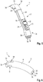
- Nachfolgendwerden Ausführungsbeispiele der Erfindung anhand einer Zeichnung näher erläutert. Darin zeigen:
- Fig. 1
- in einer schematischen Perspektivansicht eine Hörvorrichtung,
- Fig. 2
- in einer schematischen Perspektivansicht einen Tragrahmen für Elektronikkomponenten der Hörvorrichtung,
- Fig. 3
- in Ansicht gemäß
Fig. 1 ein mit dem Tragrahmen und daran befestigten Elektronikkomponenten gebildetes Elektronikgrundmodul, - Fig. 4
- in einer schematischen Perspektivansicht eine Mikrofonabdeckung für das Elektronikgrundmodul,
- Fig. 5
- in Ansicht gemäß
Fig. 1 das Elektronikgrundmodul mit der montierten Mikrofonabdeckung, - Fig. 6
- in einer schematischen Perspektivansicht die Hörvorrichtung in einem Zwischenfertigungsschritt, und
- Fig. 7, 8
- in einer schematischen Perspektivansicht Strukturelemente des Elektronikgrundmoduls, die zur Halterung des Elektronikgrundmoduls in einem Kunststoff-Formgebungswerkzeug dienen.
- Einander entsprechende Teile sind in allen Figuren stets mit gleichen Bezugszeichen versehen.
- In
Fig. 1 ist eine Hörvorrichtung, kurz als "Hörgerät 1" bezeichnet, dargestellt. Das Hörgerät 1 bildet konkret ein sogenanntes "hinter-dem-Ohr-Hörgerät". Mithin weist das Hörgerät 1 einen Grundkörper 2 auf, der Elektronikkomponenten des Hörgeräts 1 enthält und der hinter dem Ohr eines Nutzers des Hörgeräts 1 zu tragen ist. Des Weiteren weist das Hörgerät 1 ein Hörerverbindungsmittel 4 auf, mittels dessen eine Weitergabe von akustischen Ausgangssignalen des Hörgeräts 1 an ein Gehör, konkret in den Gehörgang des Nutzers des Hörgeräts 1 möglich ist. Im vorliegenden Ausführungsbeispiel handelt es sich bei dem Hörerverbindungsmittel 4 um ein Hörerverbindungskabel eines nicht näher dargestellten externen Lautsprechers, der im bestimmungsgemäßen Tragezustand des Hörgeräts 1 im Gehörgang des Nutzers angeordnet ist. Das Hörerverbindungsmittel 4 ist dabei reversibel mit dem Grundkörper 2 koppelbar ausgeführt und im bestimmungsgemäß gekoppelten Zustand (vergleicheFig. 1 ) in einem Anschlussport 6 (nachfolgend näher beschrieben, s.Fig. 6 ) mit dem Grundkörper 2 gekoppelt. - Der Grundkörper 2 weist ein im Folgenden näher beschriebenes Hauptgehäuse 8 sowie eine separat von diesem hergestellte Mikrofonabdeckung 10 auf. Im Inneren des Hauptgehäuses 8 weist der Grundkörper 2 ein Elektronikgrundmodul 12 auf. Dieses weist wiederum einen Trägerrahmen 14 auf, der durch einen vorgebogenen und gestanzten Blechstreifen 16 mit angespritzten Kunststoff-Endstücken 18 gebildet ist (s.
Fig. 2 ). Außerdem weist das Elektronikgrundmodul 12 einen vorgebogenen und mit Elektronikkomponenten bestückten Schaltungsträger 20, konkret gebildet durch eine dreidimensional geformte Leiterplatte auf. - Als Elektronikkomponenten umfasst das Elektronikgrundmodul 12 und somit auch das Hörgerät 1 einen Signalprozessor 22, eine Anzahl von weiteren Elektronikbauteilen 24 (bspw. Transistoren, Wandler und dergleichen) sowie eine Ladeelektronik 26 für eine ebenfalls an dem Elektronikgrundmodul 12 angeordnete wiederaufladbare Batterie 28. Außerdem umfasst das Elektronikgrundmodul 12 zwei Mikrofone 30 - hier als MEMS-Bauteile ausgeführt. Diese beiden Mikrofone 30 sind dabei an einem ersten Ende 32 des Elektronikgrundmoduls 12 bzw. des Hörgeräts 1 angeordnet. An einem dem ersten Ende 32 gegenüberliegenden zweiten Ende 34 des Elektronikgrundmoduls 12 - in dessen Bereich die Ladeelektronik 26 angeordnet ist - sind mehrere, konkret vier Ladekontakte 36 zum Laden der wiederaufladbaren Batterie 28 angeordnet. Diese sind über die Ladeelektronik 26 mit der Batterie 28 verbunden.
- Die Mikrofonabdeckung 10 bildet eine am ersten Ende 32 angeordnete "Endkappe", die die Mikrofone 30 von mechanischen Einflüssen schützt. Zur fluidischen Verbindung der Mikrofone 30 mit der Umgebung, und somit damit Luftschall zu den Mikrofonen 30 vordringen kann, sind zwei Schallkanäle 38 in die Mikrofonabdeckung 10 eingearbeitet.
- In
Fig. 5 ist das Elektronikgrundmodul 12 im bestimmungsgemäßen Montagezustand dargestellt. Das Elektronikgrundmodul 12 bildet dabei eine Vormontageeinheit des Hörgeräts 1. Der Schaltungsträger 20 ist hierbei mit dem Trägerrahmen 14 zusammengesteckt. Die Mikrofonabdeckung 10 ist außerdem auf das erste Ende 32, konkret auf das dortige Endstück 18 aufgesteckt oder alternativ aufgeklebt. Das Elektronikgrundmodul 12 wird nach der Montage in einem nicht näher dargestellten Kunststoff-Formgebungswerkzeug, konkret ein Spritzgießwerkzeug, kurz als Werkzeug bezeichnet, eingelegt. Anschließend wird das Elektronikgrundmodul 12 zur Ausbildung des Hauptgehäuses 8 mit Kunststoff umspritzt, mithin in diesen Kunststoff eingebettet. Die Schallkanäle 38 werden dabei offen- oder freigehalten, d. h. nicht mit Kunststoff aufgefüllt. Konkret wird die Mikrofonabdeckung 10 nicht mit dem eingespritzten Kunststoff überdeckt. - Zur Halterung und Positionierung (auch "Zentrierung") des Elektronikgrundmoduls 12 in dem Werkzeug, konkret dessen Kavität werden in nachfolgend näher beschriebener Weise Strukturelemente des Elektronikgrundmoduls 12 genutzt.
- In einem Ausführungsbeispiel wird die Mikrofonabdeckung 10 als ein solches Strukturelement genutzt. Das Elektronikgrundmodul 12 wird dabei mit der Mikrofonabdeckung 10 in eine komplementäre Aussparung der Kavität eingelegt. Die Aussparung ist dabei derart bemessen, dass ein Umströmen der Mikrofonabdeckung 10 mit Kunststoff im Spritzgießprozess verhindert und andererseits eine mechanische Fixierung des Elektronikgrundmoduls 12 ermöglicht ist. Optional greifen dabei starre oder verschiebbare Werkzeugelemente (sogenannte "Schieber") zur zusätzlichen Abdichtung und Halterung in die Schallkanäle 38 ein.
- In einem weiteren (zusätzlichen oder alternativen) Ausführungsbeispiel wird als Strukturelement zur Halterung und Positionierung des Elektronikgrundmoduls 12 der Anschlussport 6 genutzt. Der Anschlussport 6 weist eine in eines der Endstücke 18 eingeformte Aussparung auf, in oder an der mechanische Rastmittel zur Fixierung des Hörerverbindungsmittels 4 sowie elektrische Anschlusskontakte zur Kontaktierung des Hörerverbindungmittels (und somit des externen Lautsprechers) angeordnet sind (nicht näher dargestellt). Konkret greift in diesem Ausführungsbeispiel ein (optional weiterer) Schieber des Werkzeugs in den Anschlussport 6 ein und führt dabei zu einer Halterung, Positionierung sowie zu einer Abdichtung der Anschlusskontakte und Rastelemente des Anschlussports 6 gegen Umfließen mit Kunststoff.
- Zusätzlich zu der Nutzung der Mikrofonabdeckung 10 als Strukturelement lässt sich gemeinsam mit dem in den Anschlussport 6 eingreifenden Schieber eine vergleichsweise stabile Halterung und Positionierung des Elektronikgrundmoduls 12 ermöglichen.
- In einem weiteren (optional zusätzlichen oder alternativen) Ausführungsbeispiel werden als Strukturelement zur Halterungspositionierung die Ladekontakte 36, die im bestimmungsgemäßen Teilmontagezustand des Hörgeräts 1 (vergleiche
Fig. 6 ) zur Umgebung hin frei liegen, genutzt. Um einen gewissen Formschluss mit dem Werkzeug zu ermöglichen, weist dabei jeder der Ladekontakte 36 einen Zentralbereich 40 auf, der von einem Rand 42 ringförmig umgeben ist. Der Rand 42 ist dabei versetzt zu dem Zentralbereich 40 ausgeführt. In einer inFig. 7 dargestellten Variante steht der Rand 42 gegenüber dem Zentralbereich 40 zur Umgebung hin vor. In einer alternativen Variante (sieheFig. 8 ) ist der Rand 42 dagegen gegenüber dem Zentralbereich 40 zurückversetzt (mithin steht der Zentralbereich 40 zur Umgebung vor). In der Variante gemäßFig. 7 werden die Ladekontakte 36 auf komplementäre Stifte des Werkzeugs aufgesteckt, wohingegen die Ladekontakte 36 gemäßFig. 8 in komplementäre Aussparungen (Bohrungen) des Werkzeugs eingesteckt werden. - In einem optionalen Ausführungsbeispiel werden sowohl die Ladekontakte 36, der Anschlussport 6 als auch die Mikrofonabdeckung 10 zur Halterungspositionierung genutzt.
- In einem weiteren Ausführungsbeispiel wird die wiederaufladbare Batterie 28 vor dem Einlegen in das Werkzeug, insbesondere bei der Montage des Elektronikgrundmoduls 12 mit einer Isolationsfolie (nicht dargestellt) zur thermischen Isolation gegen die Wärme des eingespritzten Kunststoffs umhüllt.
- Der Gegenstand der Erfindung ist nicht auf die vorstehend beschriebenen Ausführungsbeispiele beschränkt. Vielmehr können weitere Ausführungsformen der Erfindung von dem Fachmann aus der vorstehenden Beschreibung abgeleitet werden. Insbesondere können die anhand der verschiedenen Ausführungsbeispiele beschriebenen Einzelmerkmale der Erfindung und deren Ausgestaltungsvarianten auch in anderer Weise miteinander kombiniert werden.
-
- 1
- Hörgerät
- 2
- Grundkörper
- 4
- Hörerverbindungsmittel
- 6
- Anschlussport
- 8
- Hauptgehäuse
- 10
- Mikrofonabdeckung
- 12
- Elektronikgrundmodul
- 14
- Trägerrahmen
- 16
- Blechstreifen
- 18
- Endstück
- 20
- Schaltungsträger
- 22
- Signalprozessor
- 24
- Elektronikbauteile
- 26
- Ladeelektronik
- 28
- Batterie
- 30
- Mikrofon
- 32
- erstes Ende
- 34
- zweites Ende
- 36
- Ladkontakt
- 38
- Schallkanal
- 40
- Zentralbereich
- 42
- Rand
Claims (10)
- Fertigungsverfahren für eine Hörvorrichtung (1), insbesondere für ein Hörhilfegerät, wobei verfahrensgemäß- wenigstens ein Signalprozessor (22) und wenigstens ein Mikrofon (30) in einer räumlich fest zueinander vorgegebenen Position zu einem Elektronikgrundmodul (12) vormontiert werden,- das Elektronikgrundmodul (12) in ein Kunststoff-Formgebungswerkzeug eingelegt und mittels wenigstens eines Strukturelements (10,6,36) des Elektronikgrundmoduls (12), das in einem bestimmungsgemäßen Endfertigungszustand mit der Umgebung in Kontakt steht, in dem Kunststoff-Formgebungswerkzeug positioniert und gehalten wird, und- in das Kunststoff-Formgebungswerkzeug zur Ausbildung eines Hauptgehäuses (8) für das Elektronikgrundmodul (12) Kunststoff eingebracht wird, in den das Elektronikgrundmodul (12) eingebettet wird, wobei ein Schallkanal (38) zur fluidischen Verbindung des Mikrofons (30) mit der Umgebung freigehalten wird.
- Fertigungsverfahren nach Anspruch 1,
wobei eine Mikrofonabdeckung (10), die im bestimmungsgemäßen Endfertigungszustand der Hörvorrichtung (1) das Mikrofon (30) gegenüber der Umgebung einhaust, mit dem Elektronikgrundmodul (12) verbunden wird, wobei der Schallkanal (38) die Mikrofonabdeckung (10) durchläuft. - Fertigungsverfahren nach Anspruch 2,
wobei als Strukturelement zur Halterung und Positionierung des Elektronikgrundmoduls (12) die Mikrofonabdeckung (10), zumindest deren Schallkanal (38) herangezogen wird. - Fertigungsverfahren nach einem der Ansprüche 1 bis 3,
wobei als Strukturelement zur Halterung und Positionierung des Elektronikgrundmoduls (12) an diesem angeordnete Ladekontakte (36) für eine wiederaufladbare Batterie (28) der Hörvorrichtung (1) herangezogen werden, wobei die Ladekontakte (36) einen einen Zentralbereich (40) ringartig umgebenden und gegenüber dem Zentralbereich (40) in Richtung zur Umgebung vorstehenden oder zurückversetzten Rand (42) aufweisen. - Fertigungsverfahren nach einem der Ansprüche 1 bis 4,
wobei eine wiederaufladbare Batterie (28) zur Energieversorgung zumindest des Signalprozessors (22) mit dem Elektronikgrundmodul (12) verbunden und elektrisch mit dem Signalprozessor (22) gekoppelt und gemeinsam mit dem Elektronikgrundmodul (12) in den Kunststoff eingebettet wird. - Fertigungsverfahren nach einem der Ansprüche 1 bis 5,
wobei als Kunststoff thermoplastischer Kunststoff mittels Spritzgießen in das Kunststoff-Formgebungswerkzeug eingebracht wird. - Fertigungsverfahren nach Anspruch 5 und 6,
wobei die wiederaufladbare Batterie (28) vor dem Einbetten in den Kunststoff mit einem Isolationsmaterial umgeben wird. - Fertigungsverfahren nach einem der Ansprüche 1 bis 7,
wobei als Strukturelement zur Halterung und Positionierung des Elektronikgrundmoduls (12) ein Anschlussport (6) zur wenigstens elektrischen Kopplung eines externen Lautsprechers mit dem Signalprozessor (22) herangezogen wird, insbesondere wobei ein verschiebbar gestaltetes Element des Kunststoff-Formgebungswerkzeugs zur Halterung und Positionierung mit dem Anschlussport (6) in Kontakt steht. - Fertigungsverfahren nach einem der Ansprüche 1 bis 8,
wobei der Signalprozessor (22) und das wenigstens eine Mikrofon (30) sowie gegebenenfalls die Ladekontakte (36) auf einem Trägerteil (14,20) zur Bildung des Elektronikgrundmoduls (12) zueinander positioniert und angeordnet werden. - Hörvorrichtung (1),- mit einem Elektronikgrundmodul (12), das einen Signalprozessor (22) und wenigstens ein Mikrofon (30) aufweist, die in einer räumlich fest zueinander vorgegebenen Position montiert sind, und- mit einem einstückig aus Kunststoff gefertigten Hauptgehäuse (8), in das das Elektronikgrundmodul (12) unter Freihaltung eines Schallkanals (38) zur fluidischen Verbindung des Mikrofons (30) mit der Umgebung eingebettet ist,insbesondere wobei die Hörvorrichtung (1) nach dem Fertigungsverfahren gemäß einem der Ansprüche 1 bis 9 gefertigt ist.
Applications Claiming Priority (1)
| Application Number | Priority Date | Filing Date | Title |
|---|---|---|---|
| DE102018221696.7A DE102018221696B3 (de) | 2018-12-13 | 2018-12-13 | Fertigungsverfahren für eine Hörvorrichtung und Hörvorrichtung |
Publications (3)
| Publication Number | Publication Date |
|---|---|
| EP3668119A1 true EP3668119A1 (de) | 2020-06-17 |
| EP3668119B1 EP3668119B1 (de) | 2023-06-28 |
| EP3668119C0 EP3668119C0 (de) | 2023-06-28 |
Family
ID=68581478
Family Applications (1)
| Application Number | Title | Priority Date | Filing Date |
|---|---|---|---|
| EP19208973.8A Active EP3668119B1 (de) | 2018-12-13 | 2019-11-13 | Fertigungsverfahren für eine hörvorrichtung und hörvorrichtung |
Country Status (4)
| Country | Link |
|---|---|
| US (1) | US20200196075A1 (de) |
| EP (1) | EP3668119B1 (de) |
| CN (1) | CN111328011A (de) |
| DE (1) | DE102018221696B3 (de) |
Cited By (1)
| Publication number | Priority date | Publication date | Assignee | Title |
|---|---|---|---|---|
| US11825274B2 (en) | 2019-12-21 | 2023-11-21 | Oticon A/S | Electronic module for a hearing device |
Families Citing this family (1)
| Publication number | Priority date | Publication date | Assignee | Title |
|---|---|---|---|---|
| EP4686226A1 (de) * | 2024-07-24 | 2026-01-28 | Sivantos Pte. Ltd. | Montageverfahren für ein hörgerät und hörgerät |
Citations (3)
| Publication number | Priority date | Publication date | Assignee | Title |
|---|---|---|---|---|
| US4617429A (en) * | 1985-02-04 | 1986-10-14 | Gaspare Bellafiore | Hearing aid |
| US20020032362A1 (en) * | 1997-12-18 | 2002-03-14 | Juneau Roger P. | Method of manufacturing a soft hearing aid |
| US20130129127A1 (en) * | 2011-11-23 | 2013-05-23 | Insound Medical, Inc. | Canal hearing devices and batteries for use with same |
Family Cites Families (5)
| Publication number | Priority date | Publication date | Assignee | Title |
|---|---|---|---|---|
| US6940988B1 (en) | 1998-11-25 | 2005-09-06 | Insound Medical, Inc. | Semi-permanent canal hearing device |
| CA2639555A1 (en) * | 2008-08-11 | 2008-12-15 | Hyman Ngo | High definition litho applique and emblems |
| EP2466912B1 (de) * | 2009-09-21 | 2013-06-26 | Oticon A/S | Hörvorrichtung mit einer durch eine In-dem-Ohr-Einheit wiederaufladbaren Energiequelle, deren Verwendung und Herstellungsverfahren |
| DE102010007609A1 (de) | 2010-02-11 | 2011-08-11 | Siemens Medical Instruments Pte. Ltd. | Hörerschlauch mit Zugentlastung sowie Hörhilfe |
| EP2416595B1 (de) * | 2010-08-03 | 2016-08-31 | Sivantos Pte. Ltd. | Hörinstrument mit einteiligem Spritzguss-Gehäuse |
-
2018
- 2018-12-13 DE DE102018221696.7A patent/DE102018221696B3/de active Active
-
2019
- 2019-11-13 EP EP19208973.8A patent/EP3668119B1/de active Active
- 2019-12-12 CN CN201911272210.5A patent/CN111328011A/zh active Pending
- 2019-12-13 US US16/713,316 patent/US20200196075A1/en not_active Abandoned
Patent Citations (3)
| Publication number | Priority date | Publication date | Assignee | Title |
|---|---|---|---|---|
| US4617429A (en) * | 1985-02-04 | 1986-10-14 | Gaspare Bellafiore | Hearing aid |
| US20020032362A1 (en) * | 1997-12-18 | 2002-03-14 | Juneau Roger P. | Method of manufacturing a soft hearing aid |
| US20130129127A1 (en) * | 2011-11-23 | 2013-05-23 | Insound Medical, Inc. | Canal hearing devices and batteries for use with same |
Cited By (2)
| Publication number | Priority date | Publication date | Assignee | Title |
|---|---|---|---|---|
| US11825274B2 (en) | 2019-12-21 | 2023-11-21 | Oticon A/S | Electronic module for a hearing device |
| US12167207B2 (en) | 2019-12-21 | 2024-12-10 | Oticon A/S | Electronic module for a hearing device |
Also Published As
| Publication number | Publication date |
|---|---|
| DE102018221696B3 (de) | 2020-02-27 |
| EP3668119B1 (de) | 2023-06-28 |
| US20200196075A1 (en) | 2020-06-18 |
| CN111328011A (zh) | 2020-06-23 |
| EP3668119C0 (de) | 2023-06-28 |
Similar Documents
| Publication | Publication Date | Title |
|---|---|---|
| EP3094111A1 (de) | Hörgerät | |
| DE102007042324B4 (de) | In-dem-Ohr-Hörgerät mit Kontaktmittel und zugehöriges Batterieladegerät | |
| DE102012214466B4 (de) | Wiederaufladbarer Batteriepack | |
| DE19882961C2 (de) | Hörhilfe | |
| EP3101918B1 (de) | Hörgerät | |
| EP3419311B1 (de) | Hörgerät | |
| EP2680611B1 (de) | Hybrider Hörinstrument-Konnektor | |
| DE112019003955T5 (de) | Integrierte unterbaugruppe für eine tragbare audiovorrichtung | |
| DE102007047335A1 (de) | Hörgerät | |
| EP2654322B1 (de) | Hörinstrument mit Schallschlauch-Steckverbindung | |
| EP3668119B1 (de) | Fertigungsverfahren für eine hörvorrichtung und hörvorrichtung | |
| DE212024000221U1 (de) | Ohrclip-Kopfhörer | |
| EP1317163B1 (de) | Hörgerät | |
| EP3905722A1 (de) | Batteriemodul und hörvorrichtung | |
| DE112020003989T5 (de) | Schallausgabevorrichtung | |
| DE102010041695A1 (de) | Im-Ohr-Hörinstrument und Ohrstück sowie Herstellungsverfahren | |
| DE102010051626B4 (de) | Hörgerät, Verbinder, Verwendung eines Verbinders und System zum Verbinden eines Hörgeräts mit einem Kabel | |
| DE102007025936B4 (de) | Hörgerät mit am Gehäuserahmen befestigtem Anschlussstück | |
| EP3614699A1 (de) | Hörinstrument mit einer kopplungseinheit zur schwingungsgedämpften lagerung eines hörers | |
| DE102008020926B4 (de) | Drucktaster für ein Hörgerät | |
| EP1915029B1 (de) | Hörgerät mit einer Montagevorrichtung für eine Komponente des Hörgeräts und Verfahren zum Befestigen der Komponente | |
| EP2218268A1 (de) | Hörvorrichtung mit batterieklappenmodul | |
| EP1998593A1 (de) | Ohrstück für eine Hörvorrichtung mit Sicherungsring | |
| WO2023052436A1 (de) | Magnetischer steckverbinder für einen galvanischen ladeanschluss eines elektronischen geräts, insbesondere eines hörinstruments | |
| EP3419312B1 (de) | Hörgerät |
Legal Events
| Date | Code | Title | Description |
|---|---|---|---|
| PUAI | Public reference made under article 153(3) epc to a published international application that has entered the european phase |
Free format text: ORIGINAL CODE: 0009012 |
|
| STAA | Information on the status of an ep patent application or granted ep patent |
Free format text: STATUS: THE APPLICATION HAS BEEN PUBLISHED |
|
| AK | Designated contracting states |
Kind code of ref document: A1 Designated state(s): AL AT BE BG CH CY CZ DE DK EE ES FI FR GB GR HR HU IE IS IT LI LT LU LV MC MK MT NL NO PL PT RO RS SE SI SK SM TR |
|
| AX | Request for extension of the european patent |
Extension state: BA ME |
|
| STAA | Information on the status of an ep patent application or granted ep patent |
Free format text: STATUS: REQUEST FOR EXAMINATION WAS MADE |
|
| 17P | Request for examination filed |
Effective date: 20201215 |
|
| RBV | Designated contracting states (corrected) |
Designated state(s): AL AT BE BG CH CY CZ DE DK EE ES FI FR GB GR HR HU IE IS IT LI LT LU LV MC MK MT NL NO PL PT RO RS SE SI SK SM TR |
|
| STAA | Information on the status of an ep patent application or granted ep patent |
Free format text: STATUS: EXAMINATION IS IN PROGRESS |
|
| 17Q | First examination report despatched |
Effective date: 20210511 |
|
| GRAP | Despatch of communication of intention to grant a patent |
Free format text: ORIGINAL CODE: EPIDOSNIGR1 |
|
| STAA | Information on the status of an ep patent application or granted ep patent |
Free format text: STATUS: GRANT OF PATENT IS INTENDED |
|
| INTG | Intention to grant announced |
Effective date: 20230125 |
|
| GRAS | Grant fee paid |
Free format text: ORIGINAL CODE: EPIDOSNIGR3 |
|
| GRAA | (expected) grant |
Free format text: ORIGINAL CODE: 0009210 |
|
| STAA | Information on the status of an ep patent application or granted ep patent |
Free format text: STATUS: THE PATENT HAS BEEN GRANTED |
|
| AK | Designated contracting states |
Kind code of ref document: B1 Designated state(s): AL AT BE BG CH CY CZ DE DK EE ES FI FR GB GR HR HU IE IS IT LI LT LU LV MC MK MT NL NO PL PT RO RS SE SI SK SM TR |
|
| REG | Reference to a national code |
Ref country code: CH Ref legal event code: EP |
|
| REG | Reference to a national code |
Ref country code: AT Ref legal event code: REF Ref document number: 1583814 Country of ref document: AT Kind code of ref document: T Effective date: 20230715 |
|
| REG | Reference to a national code |
Ref country code: IE Ref legal event code: FG4D Free format text: LANGUAGE OF EP DOCUMENT: GERMAN |
|
| REG | Reference to a national code |
Ref country code: DE Ref legal event code: R096 Ref document number: 502019008316 Country of ref document: DE |
|
| U01 | Request for unitary effect filed |
Effective date: 20230720 |
|
| U07 | Unitary effect registered |
Designated state(s): AT BE BG DE DK EE FI FR IT LT LU LV MT NL PT SE SI Effective date: 20230803 |
|
| REG | Reference to a national code |
Ref country code: LT Ref legal event code: MG9D |
|
| PG25 | Lapsed in a contracting state [announced via postgrant information from national office to epo] |
Ref country code: NO Free format text: LAPSE BECAUSE OF FAILURE TO SUBMIT A TRANSLATION OF THE DESCRIPTION OR TO PAY THE FEE WITHIN THE PRESCRIBED TIME-LIMIT Effective date: 20230928 |
|
| PG25 | Lapsed in a contracting state [announced via postgrant information from national office to epo] |
Ref country code: RS Free format text: LAPSE BECAUSE OF FAILURE TO SUBMIT A TRANSLATION OF THE DESCRIPTION OR TO PAY THE FEE WITHIN THE PRESCRIBED TIME-LIMIT Effective date: 20230628 Ref country code: HR Free format text: LAPSE BECAUSE OF FAILURE TO SUBMIT A TRANSLATION OF THE DESCRIPTION OR TO PAY THE FEE WITHIN THE PRESCRIBED TIME-LIMIT Effective date: 20230628 Ref country code: GR Free format text: LAPSE BECAUSE OF FAILURE TO SUBMIT A TRANSLATION OF THE DESCRIPTION OR TO PAY THE FEE WITHIN THE PRESCRIBED TIME-LIMIT Effective date: 20230929 |
|
| U20 | Renewal fee for the european patent with unitary effect paid |
Year of fee payment: 5 Effective date: 20231116 |
|
| PG25 | Lapsed in a contracting state [announced via postgrant information from national office to epo] |
Ref country code: SK Free format text: LAPSE BECAUSE OF FAILURE TO SUBMIT A TRANSLATION OF THE DESCRIPTION OR TO PAY THE FEE WITHIN THE PRESCRIBED TIME-LIMIT Effective date: 20230628 |
|
| PG25 | Lapsed in a contracting state [announced via postgrant information from national office to epo] |
Ref country code: ES Free format text: LAPSE BECAUSE OF FAILURE TO SUBMIT A TRANSLATION OF THE DESCRIPTION OR TO PAY THE FEE WITHIN THE PRESCRIBED TIME-LIMIT Effective date: 20230628 |
|
| PG25 | Lapsed in a contracting state [announced via postgrant information from national office to epo] |
Ref country code: IS Free format text: LAPSE BECAUSE OF FAILURE TO SUBMIT A TRANSLATION OF THE DESCRIPTION OR TO PAY THE FEE WITHIN THE PRESCRIBED TIME-LIMIT Effective date: 20231028 |
|
| PG25 | Lapsed in a contracting state [announced via postgrant information from national office to epo] |
Ref country code: SM Free format text: LAPSE BECAUSE OF FAILURE TO SUBMIT A TRANSLATION OF THE DESCRIPTION OR TO PAY THE FEE WITHIN THE PRESCRIBED TIME-LIMIT Effective date: 20230628 Ref country code: SK Free format text: LAPSE BECAUSE OF FAILURE TO SUBMIT A TRANSLATION OF THE DESCRIPTION OR TO PAY THE FEE WITHIN THE PRESCRIBED TIME-LIMIT Effective date: 20230628 Ref country code: RO Free format text: LAPSE BECAUSE OF FAILURE TO SUBMIT A TRANSLATION OF THE DESCRIPTION OR TO PAY THE FEE WITHIN THE PRESCRIBED TIME-LIMIT Effective date: 20230628 Ref country code: IS Free format text: LAPSE BECAUSE OF FAILURE TO SUBMIT A TRANSLATION OF THE DESCRIPTION OR TO PAY THE FEE WITHIN THE PRESCRIBED TIME-LIMIT Effective date: 20231028 Ref country code: ES Free format text: LAPSE BECAUSE OF FAILURE TO SUBMIT A TRANSLATION OF THE DESCRIPTION OR TO PAY THE FEE WITHIN THE PRESCRIBED TIME-LIMIT Effective date: 20230628 Ref country code: CZ Free format text: LAPSE BECAUSE OF FAILURE TO SUBMIT A TRANSLATION OF THE DESCRIPTION OR TO PAY THE FEE WITHIN THE PRESCRIBED TIME-LIMIT Effective date: 20230628 |
|
| PG25 | Lapsed in a contracting state [announced via postgrant information from national office to epo] |
Ref country code: PL Free format text: LAPSE BECAUSE OF FAILURE TO SUBMIT A TRANSLATION OF THE DESCRIPTION OR TO PAY THE FEE WITHIN THE PRESCRIBED TIME-LIMIT Effective date: 20230628 |
|
| REG | Reference to a national code |
Ref country code: DE Ref legal event code: R026 Ref document number: 502019008316 Country of ref document: DE |
|
| PLBI | Opposition filed |
Free format text: ORIGINAL CODE: 0009260 |
|
| PLAB | Opposition data, opponent's data or that of the opponent's representative modified |
Free format text: ORIGINAL CODE: 0009299OPPO |
|
| PLAX | Notice of opposition and request to file observation + time limit sent |
Free format text: ORIGINAL CODE: EPIDOSNOBS2 |
|
| 26 | Opposition filed |
Opponent name: OTICON A/S Effective date: 20240328 |
|
| R26 | Opposition filed (corrected) |
Opponent name: OTICON A/S Effective date: 20240328 |
|
| PG25 | Lapsed in a contracting state [announced via postgrant information from national office to epo] |
Ref country code: MC Free format text: LAPSE BECAUSE OF FAILURE TO SUBMIT A TRANSLATION OF THE DESCRIPTION OR TO PAY THE FEE WITHIN THE PRESCRIBED TIME-LIMIT Effective date: 20230628 |
|
| PG25 | Lapsed in a contracting state [announced via postgrant information from national office to epo] |
Ref country code: MC Free format text: LAPSE BECAUSE OF FAILURE TO SUBMIT A TRANSLATION OF THE DESCRIPTION OR TO PAY THE FEE WITHIN THE PRESCRIBED TIME-LIMIT Effective date: 20230628 |
|
| PLBB | Reply of patent proprietor to notice(s) of opposition received |
Free format text: ORIGINAL CODE: EPIDOSNOBS3 |
|
| REG | Reference to a national code |
Ref country code: IE Ref legal event code: MM4A |
|
| PG25 | Lapsed in a contracting state [announced via postgrant information from national office to epo] |
Ref country code: IE Free format text: LAPSE BECAUSE OF NON-PAYMENT OF DUE FEES Effective date: 20231113 |
|
| PG25 | Lapsed in a contracting state [announced via postgrant information from national office to epo] |
Ref country code: IE Free format text: LAPSE BECAUSE OF NON-PAYMENT OF DUE FEES Effective date: 20231113 |
|
| U20 | Renewal fee for the european patent with unitary effect paid |
Year of fee payment: 6 Effective date: 20241022 |
|
| PLCK | Communication despatched that opposition was rejected |
Free format text: ORIGINAL CODE: EPIDOSNREJ1 |
|
| PG25 | Lapsed in a contracting state [announced via postgrant information from national office to epo] |
Ref country code: CY Free format text: LAPSE BECAUSE OF FAILURE TO SUBMIT A TRANSLATION OF THE DESCRIPTION OR TO PAY THE FEE WITHIN THE PRESCRIBED TIME-LIMIT; INVALID AB INITIO Effective date: 20191113 |
|
| PG25 | Lapsed in a contracting state [announced via postgrant information from national office to epo] |
Ref country code: HU Free format text: LAPSE BECAUSE OF FAILURE TO SUBMIT A TRANSLATION OF THE DESCRIPTION OR TO PAY THE FEE WITHIN THE PRESCRIBED TIME-LIMIT; INVALID AB INITIO Effective date: 20191113 |
|
| APAH | Appeal reference modified |
Free format text: ORIGINAL CODE: EPIDOSCREFNO |
|
| APBP | Date of receipt of notice of appeal recorded |
Free format text: ORIGINAL CODE: EPIDOSNNOA2O |
|
| APBQ | Date of receipt of statement of grounds of appeal recorded |
Free format text: ORIGINAL CODE: EPIDOSNNOA3O |
|
| U20 | Renewal fee for the european patent with unitary effect paid |
Year of fee payment: 7 Effective date: 20251022 |
|
| REG | Reference to a national code |
Ref country code: CH Ref legal event code: U11 Free format text: ST27 STATUS EVENT CODE: U-0-0-U10-U11 (AS PROVIDED BY THE NATIONAL OFFICE) Effective date: 20251201 |
|
| PG25 | Lapsed in a contracting state [announced via postgrant information from national office to epo] |
Ref country code: TR Free format text: LAPSE BECAUSE OF FAILURE TO SUBMIT A TRANSLATION OF THE DESCRIPTION OR TO PAY THE FEE WITHIN THE PRESCRIBED TIME-LIMIT Effective date: 20230628 |
|
| PGFP | Annual fee paid to national office [announced via postgrant information from national office to epo] |
Ref country code: GB Payment date: 20251022 Year of fee payment: 7 |
|
| PGFP | Annual fee paid to national office [announced via postgrant information from national office to epo] |
Ref country code: CH Payment date: 20251201 Year of fee payment: 7 |