EP3667825A1 - Leiteranschlussklemme - Google Patents
Leiteranschlussklemme Download PDFInfo
- Publication number
- EP3667825A1 EP3667825A1 EP19214200.8A EP19214200A EP3667825A1 EP 3667825 A1 EP3667825 A1 EP 3667825A1 EP 19214200 A EP19214200 A EP 19214200A EP 3667825 A1 EP3667825 A1 EP 3667825A1
- Authority
- EP
- European Patent Office
- Prior art keywords
- main housing
- actuating lever
- housing part
- conductor
- cover part
- Prior art date
- Legal status (The legal status is an assumption and is not a legal conclusion. Google has not performed a legal analysis and makes no representation as to the accuracy of the status listed.)
- Granted
Links
Images



Classifications
-
- H—ELECTRICITY
- H01—ELECTRIC ELEMENTS
- H01R—ELECTRICALLY-CONDUCTIVE CONNECTIONS; STRUCTURAL ASSOCIATIONS OF A PLURALITY OF MUTUALLY-INSULATED ELECTRICAL CONNECTING ELEMENTS; COUPLING DEVICES; CURRENT COLLECTORS
- H01R13/00—Details of coupling devices of the kinds covered by groups H01R12/70 or H01R24/00 - H01R33/00
- H01R13/46—Bases; Cases
- H01R13/502—Bases; Cases composed of different pieces
- H01R13/506—Bases; Cases composed of different pieces assembled by snap action of the parts
-
- H—ELECTRICITY
- H01—ELECTRIC ELEMENTS
- H01R—ELECTRICALLY-CONDUCTIVE CONNECTIONS; STRUCTURAL ASSOCIATIONS OF A PLURALITY OF MUTUALLY-INSULATED ELECTRICAL CONNECTING ELEMENTS; COUPLING DEVICES; CURRENT COLLECTORS
- H01R13/00—Details of coupling devices of the kinds covered by groups H01R12/70 or H01R24/00 - H01R33/00
- H01R13/40—Securing contact members in or to a base or case; Insulating of contact members
- H01R13/42—Securing in a demountable manner
- H01R13/428—Securing in a demountable manner by resilient locking means on the contact members; by locking means on resilient contact members
-
- H—ELECTRICITY
- H01—ELECTRIC ELEMENTS
- H01R—ELECTRICALLY-CONDUCTIVE CONNECTIONS; STRUCTURAL ASSOCIATIONS OF A PLURALITY OF MUTUALLY-INSULATED ELECTRICAL CONNECTING ELEMENTS; COUPLING DEVICES; CURRENT COLLECTORS
- H01R4/00—Electrically-conductive connections between two or more conductive members in direct contact, i.e. touching one another; Means for effecting or maintaining such contact; Electrically-conductive connections having two or more spaced connecting locations for conductors and using contact members penetrating insulation
- H01R4/28—Clamped connections, spring connections
- H01R4/48—Clamped connections, spring connections utilising a spring, clip, or other resilient member
-
- H—ELECTRICITY
- H01—ELECTRIC ELEMENTS
- H01R—ELECTRICALLY-CONDUCTIVE CONNECTIONS; STRUCTURAL ASSOCIATIONS OF A PLURALITY OF MUTUALLY-INSULATED ELECTRICAL CONNECTING ELEMENTS; COUPLING DEVICES; CURRENT COLLECTORS
- H01R13/00—Details of coupling devices of the kinds covered by groups H01R12/70 or H01R24/00 - H01R33/00
- H01R13/02—Contact members
- H01R13/10—Sockets for co-operation with pins or blades
- H01R13/11—Resilient sockets
-
- H—ELECTRICITY
- H01—ELECTRIC ELEMENTS
- H01R—ELECTRICALLY-CONDUCTIVE CONNECTIONS; STRUCTURAL ASSOCIATIONS OF A PLURALITY OF MUTUALLY-INSULATED ELECTRICAL CONNECTING ELEMENTS; COUPLING DEVICES; CURRENT COLLECTORS
- H01R13/00—Details of coupling devices of the kinds covered by groups H01R12/70 or H01R24/00 - H01R33/00
- H01R13/40—Securing contact members in or to a base or case; Insulating of contact members
- H01R13/42—Securing in a demountable manner
- H01R13/426—Securing by a separate resilient retaining piece supported by base or case, e.g. collar or metal contact-retention clip
-
- H—ELECTRICITY
- H01—ELECTRIC ELEMENTS
- H01R—ELECTRICALLY-CONDUCTIVE CONNECTIONS; STRUCTURAL ASSOCIATIONS OF A PLURALITY OF MUTUALLY-INSULATED ELECTRICAL CONNECTING ELEMENTS; COUPLING DEVICES; CURRENT COLLECTORS
- H01R13/00—Details of coupling devices of the kinds covered by groups H01R12/70 or H01R24/00 - H01R33/00
- H01R13/46—Bases; Cases
- H01R13/50—Bases; Cases formed as an integral body
-
- H—ELECTRICITY
- H01—ELECTRIC ELEMENTS
- H01R—ELECTRICALLY-CONDUCTIVE CONNECTIONS; STRUCTURAL ASSOCIATIONS OF A PLURALITY OF MUTUALLY-INSULATED ELECTRICAL CONNECTING ELEMENTS; COUPLING DEVICES; CURRENT COLLECTORS
- H01R4/00—Electrically-conductive connections between two or more conductive members in direct contact, i.e. touching one another; Means for effecting or maintaining such contact; Electrically-conductive connections having two or more spaced connecting locations for conductors and using contact members penetrating insulation
- H01R4/28—Clamped connections, spring connections
- H01R4/48—Clamped connections, spring connections utilising a spring, clip, or other resilient member
- H01R4/4809—Clamped connections, spring connections utilising a spring, clip, or other resilient member using a leaf spring to bias the conductor toward the busbar
- H01R4/4828—Spring-activating arrangements mounted on or integrally formed with the spring housing
- H01R4/483—Pivoting arrangements, e.g. lever pushing on the spring
-
- H—ELECTRICITY
- H01—ELECTRIC ELEMENTS
- H01R—ELECTRICALLY-CONDUCTIVE CONNECTIONS; STRUCTURAL ASSOCIATIONS OF A PLURALITY OF MUTUALLY-INSULATED ELECTRICAL CONNECTING ELEMENTS; COUPLING DEVICES; CURRENT COLLECTORS
- H01R4/00—Electrically-conductive connections between two or more conductive members in direct contact, i.e. touching one another; Means for effecting or maintaining such contact; Electrically-conductive connections having two or more spaced connecting locations for conductors and using contact members penetrating insulation
- H01R4/28—Clamped connections, spring connections
- H01R4/48—Clamped connections, spring connections utilising a spring, clip, or other resilient member
- H01R4/4809—Clamped connections, spring connections utilising a spring, clip, or other resilient member using a leaf spring to bias the conductor toward the busbar
- H01R4/484—Spring housing details
-
- H—ELECTRICITY
- H01—ELECTRIC ELEMENTS
- H01R—ELECTRICALLY-CONDUCTIVE CONNECTIONS; STRUCTURAL ASSOCIATIONS OF A PLURALITY OF MUTUALLY-INSULATED ELECTRICAL CONNECTING ELEMENTS; COUPLING DEVICES; CURRENT COLLECTORS
- H01R9/00—Structural associations of a plurality of mutually-insulated electrical connecting elements, e.g. terminal strips or terminal blocks; Terminals or binding posts mounted upon a base or in a case; Bases therefor
- H01R9/11—End pieces for multiconductor cables supported by the cable and for facilitating connections to other conductive members, e.g. for liquid cooled welding cables
-
- H—ELECTRICITY
- H01—ELECTRIC ELEMENTS
- H01R—ELECTRICALLY-CONDUCTIVE CONNECTIONS; STRUCTURAL ASSOCIATIONS OF A PLURALITY OF MUTUALLY-INSULATED ELECTRICAL CONNECTING ELEMENTS; COUPLING DEVICES; CURRENT COLLECTORS
- H01R4/00—Electrically-conductive connections between two or more conductive members in direct contact, i.e. touching one another; Means for effecting or maintaining such contact; Electrically-conductive connections having two or more spaced connecting locations for conductors and using contact members penetrating insulation
- H01R4/28—Clamped connections, spring connections
- H01R4/48—Clamped connections, spring connections utilising a spring, clip, or other resilient member
- H01R4/4809—Clamped connections, spring connections utilising a spring, clip, or other resilient member using a leaf spring to bias the conductor toward the busbar
- H01R4/48185—Clamped connections, spring connections utilising a spring, clip, or other resilient member using a leaf spring to bias the conductor toward the busbar adapted for axial insertion of a wire end
- H01R4/4819—Clamped connections, spring connections utilising a spring, clip, or other resilient member using a leaf spring to bias the conductor toward the busbar adapted for axial insertion of a wire end the spring shape allowing insertion of the conductor end when the spring is unbiased
- H01R4/4821—Single-blade spring
-
- H—ELECTRICITY
- H01—ELECTRIC ELEMENTS
- H01R—ELECTRICALLY-CONDUCTIVE CONNECTIONS; STRUCTURAL ASSOCIATIONS OF A PLURALITY OF MUTUALLY-INSULATED ELECTRICAL CONNECTING ELEMENTS; COUPLING DEVICES; CURRENT COLLECTORS
- H01R4/00—Electrically-conductive connections between two or more conductive members in direct contact, i.e. touching one another; Means for effecting or maintaining such contact; Electrically-conductive connections having two or more spaced connecting locations for conductors and using contact members penetrating insulation
- H01R4/28—Clamped connections, spring connections
- H01R4/48—Clamped connections, spring connections utilising a spring, clip, or other resilient member
- H01R4/4809—Clamped connections, spring connections utilising a spring, clip, or other resilient member using a leaf spring to bias the conductor toward the busbar
- H01R4/4828—Spring-activating arrangements mounted on or integrally formed with the spring housing
- H01R4/4835—Mechanically bistable arrangements, e.g. locked by the housing when the spring is biased
-
- H—ELECTRICITY
- H01—ELECTRIC ELEMENTS
- H01R—ELECTRICALLY-CONDUCTIVE CONNECTIONS; STRUCTURAL ASSOCIATIONS OF A PLURALITY OF MUTUALLY-INSULATED ELECTRICAL CONNECTING ELEMENTS; COUPLING DEVICES; CURRENT COLLECTORS
- H01R4/00—Electrically-conductive connections between two or more conductive members in direct contact, i.e. touching one another; Means for effecting or maintaining such contact; Electrically-conductive connections having two or more spaced connecting locations for conductors and using contact members penetrating insulation
- H01R4/28—Clamped connections, spring connections
- H01R4/48—Clamped connections, spring connections utilising a spring, clip, or other resilient member
- H01R4/4809—Clamped connections, spring connections utilising a spring, clip, or other resilient member using a leaf spring to bias the conductor toward the busbar
- H01R4/4846—Busbar details
- H01R4/4852—Means for improving the contact with the conductor, e.g. uneven wire-receiving surface
Definitions
- Such conductor terminals are used to clamp at least one electrical conductor to the contact insert by clamping by means of the clamping spring.
- a conductor terminal is for example from the DE 10 2014 102 517 A1 known.
- DE 10 2010 060 252 B4 an electrical connection unit is known.
- DE 20 2006 013 216 U1 a clamping device for a stripping-free conductor connection is known.
- Other conductor terminals are from the DE 20 2014 011 234 U1 and the DE 10 2014 114 021 A1 known.
- the invention has for its object to further improve such a conductor terminal with regard to mechanical robustness.
- the actuating lever is integrated into the stiffening and stabilization of the mechanical structure of the conductor connecting terminal, in particular of the insulating material housing, and thus has an additional function in addition to the function for actuating the clamping spring, namely increasing the mechanical stability of the conductor connecting terminal.
- a tensile force is applied to the cover part, for example by pulling from the outside on the electrical conductor clamped on the contact insert, then in the present invention the cover part can, in addition to other fixing elements, such as for example the positive fixing by means of the positive locking element, Support on the further fixation provided by the holding edge of the actuating lever and transfer the forces to other parts of the insulating material housing. In this way, loosening or pulling out the cover part from the main housing part can be effectively counteracted. As a result, the maximum permissible conductor pull-out forces of the conductor terminal can be increased.
- the at least one form-locking element is used to fix the cover part to the main housing part.
- a form-locking element can be designed, for example, as a locking element, so that the cover part can be fixed to the housing part by means of locking by means of this form-locking element or locking element.
- the at least one form-locking element can be an integral part of the cover part, e.g. in that the at least one form-locking element is formed in one piece with the cover part.
- the cover part can, for example, have a corresponding counter contour which interacts with the holding edge for securing the cover part on the main housing part.
- the contact insert has at least one clamping spring.
- the clamping spring can have a contact leg, a spring arch adjoining the contact leg and a clamping leg adjoining the spring arch.
- the clamping leg can have a clamping edge at its free end ends that serve to clamp the electrical conductor.
- the contact leg serves for the mechanical fastening and support of the clamping spring on at least part of the conductor connection terminal, for example on the actuating lever, on a busbar and / or on the insulating material housing.
- the contact insert can additionally have, for example, a busbar which is coupled to the clamping spring.
- the busbar can have a conductor support area on which the electrical conductor to be clamped is pressed against the busbar by means of the clamping spring. The clamping point is then formed between the clamping edge of the clamping leg and the conductor contact area of the busbar.
- the actuating lever has at least one open and one closed position.
- the open position of the actuating lever can correspond to an open clamping point
- the closed position of the actuating lever can correspond to a closed clamping point.
- an electrical conductor is clamped by means of the clamping spring; when the clamping point is open, the electrical conductor can be removed from the clamping point essentially without effort or inserted into the clamping point.
- the main housing part can, for example, have a recess or opening which can be used to arrange the contact insert in the main housing part.
- the cover part is used, which can, for example, be fully or partially inserted into the recess or opening and can be fixed therein.
- the insulating material housing has a conductor insertion opening.
- the conductor insertion opening can be arranged on the main housing part or on the cover part.
- the cover part can, for example, have a conductor insertion channel adjoining the conductor insertion opening, through which an electrical conductor can be guided specifically to the clamping point.
- the cover part is secured against detaching from the main housing part at least when the actuating lever is closed by means of the at least one retaining edge in that the at least one form-locking element of the cover part is encompassed by the at least one holding edge.
- the positive locking element which already serves to fix the cover part on the main housing part, is additionally used for the fixation between the actuating lever and the cover part.
- the mentioned counter-contour of the cover part can be realized by the at least one form-fitting element, for example by a fixing edge of the form-fitting element acting as a counterpart to the holding edge.
- an electrical conductor on the contact insert can be fixed by spring force by means of the clamping spring, a tensile force exerted on the electrical conductor outside the conductor connecting terminal being transferable to the contact insert and from there to the cover part and from the cover part to the actuating lever . Due to the power chain formed in this way, the tensile force exerted on the electrical conductor can be effectively transmitted to the actuating lever and thus at least partially derived from the cover part.
- the tensile force exerted on the electrical conductor outside the conductor connection terminal can be transmitted from the actuating lever to the main housing part.
- the aforementioned power chain can be continued up to the main housing part, that is to say to a point at which the actuating lever is in turn fastened and / or supported on the main housing part.
- the actuating lever has a spring actuation area on which at least one spring actuation element is arranged for deflecting the clamping spring, and a manual grip area on which the actuation lever is to be operated manually, the holding edge being arranged in the manual grip area is.
- the holding edge can be arranged at a suitable point on the actuating lever without affecting the areas of the actuating lever which affect the actuating mechanism of the clamping spring or which may have to be redesigned.
- the actuating lever has at least one recess on its side facing the cover part, on which the holding edge is arranged.
- the recess with the holding edge can be arranged, so to speak, on the inside of the actuation lever and in particular on the inside of the manual actuation area.
- the fixing of the cover part by means of the actuating lever can be made particularly efficient.
- this fixation is not disturbing for the manual actuation of the actuation lever and the visual appearance of the conductor connection terminal.
- the recess can in particular be designed in the manner of a blind hole, that is to say as a recess which does not completely penetrate the actuating lever or the manual actuating region.
- an area of the form-locking element of the cover part protruding from the main housing part projects into the recess in the closed state of the actuating lever.
- the actuating lever can be locked in place on the main housing part at least in the closed position. This can ensure that the actuating lever remains in the closed position in a defined manner, even if the conductor connecting terminal is loaded, for example, by vibration or similar external influences.
- the latching fixation of the actuating lever on the main housing part can be realized, for example, in that the main housing part has at least one housing latch element which is designed to interact with at least one lever latch element arranged on the actuating lever.
- the actuating lever can be locked in place, at least in the closed position, by the cooperation of the lever locking element with the housing locking element.
- the lever locking element can be designed, for example, as one or two locking pins projecting laterally from the manual actuation area on opposite sides.
- the housing locking element can be designed as a locking recess assigned to the respective lever locking element in a side wall of the main housing part. The locking pins can then engage in the locking recesses of the main housing part.
- the main housing part has a resilient latching tongue which, when the cover part is attached to the main housing part, engages under the form-locking element of the cover part and engages behind with a latching edge.
- the main housing part on the side facing the actuating lever can have a latching tongue projecting parallel to the direction of insertion of the conductor with an end latching hook.
- the form-locking element of the cover part can be designed, for example, as a bow-shaped retaining tab, which is latched under and behind the latching tongue with its latching hook at the end. The locking edge is thus formed on the locking hook at the end.
- the cover part has a further form-fitting element on the side facing away from the form-fitting element, which is set up for a form-fitting connection with a holding element of the main housing part.
- the cover part can be positively connected to the main housing part at at least two spaced apart locations.
- the main housing part has an upper side on which the actuating lever protrudes from the main housing part at least in the open position and a lower side opposite the upper side, the main housing part having a plurality of vertical walls connecting the upper side to the underside, wherein a side fixing element is arranged on at least one vertical wall, by means of which the cover part can be fixed laterally by positive locking on the main housing part.
- a side fixing element is arranged on at least one vertical wall, by means of which the cover part can be fixed laterally by positive locking on the main housing part.
- a side positive locking element assigned to the side fixing element can be arranged on the cover part, with which the positive connection to the side fixing element is produced when the cover part is attached to the main housing part.
- the form-fitting connection can be designed, for example, as a latching connection, in which case the side fixing element can be designed as a latching element, for example with a latching tongue aligned parallel to the direction of insertion of the conductor, with an end latching hook.
- Another possible implementation for the side fixing element is the design as a locking pin and / or with a dovetail geometry.
- the vertical walls can in particular be designed as side walls of the main housing part, that is to say as side walls which limit the main housing part to the outside.
- the conductor connection terminal is designed as a multi-pole conductor connection terminal that has a plurality of conductor connection chambers that are separate from one another
- the insulating material housing can also form inner partition walls in addition to the side walls, through which additional vertical walls can be realized.
- the side fixing elements mentioned can also be implemented on such partition walls.
- the indefinite term “a” is not to be understood as a numerical word. So if e.g. When one speaks of a component, this should be interpreted in the sense of "at least one component”. Insofar as angles are given in degrees, they refer to a circular dimension of 360 degrees (360 °).
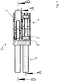
- the Figure 1 first shows the main components of the conductor terminal 1.
- the conductor terminal 1 is formed in the illustrated embodiment as a two-pin connector.
- the conductor connection terminal 1 has a connector region 6 and a conductor connection region 7.
- the conductor connection terminal 1 has an insulating material housing 2 that extends over the connector region 6 and the conductor connection region 7.
- the conductor connection terminal 1 also has an actuating lever 5 for each of the two contact inserts arranged in the insulating material housing 2 (as will be explained below).
- the operating lever 5 is in the upper area Figure 1 reproduced in the closed position, in the lower area in the open position.
- section lines AA and BB are drawn in, using which the Figures 2 and 3rd the inner structure of the conductor terminal 1 is to be explained.
- the conductor connection terminal 1 is constructed identically in both areas, that is to say in the area of section line BB and section line AA, so that the statements apply to both areas.
- section line AA has a vertical offset approximately in the middle of the conductor connection area 7, so that the section line AA does not reflect a continuous section plane.
- the Figure 2 shows the section along the section line BB.
- the insulating material housing 2 is formed at least in two parts, with a main housing part 20 and a cover part 21 that is inserted in a recess in the main housing part 20 and is fastened in a form-fitting manner.
- a contact insert in the conductor connection area 7 which has a clamping spring 4 and a busbar 3.
- the clamping spring 4 has a contact leg 40, a spring arch 41 adjoining the contact leg 40 and a clamping leg 42 adjoining the spring arch 41.
- the clamping leg 42 has a clamping edge 43 at its free end.
- the busbar 3 has a conductor connection area 30 in which, for example, a bead can be formed.
- An electrical conductor can be clamped at a clamping point formed between the clamping edge 43 and the conductor connection area 30.
- the electrical conductor can be inserted into the insulating material housing 2 through a conductor insertion opening 22.
- the conductor insertion opening 22 can be arranged in the cover part 21.
- the conductor connection terminal 1 has a plug contact, which in this exemplary embodiment is designed as a socket contact designed as a fork contact with opposing contact limbs 61, 62.
- the contact forks 61, 62 are connected to one another via a vertically running connecting section 63.
- the busbar 3 can be formed in one piece in the form of a metal part with the contact legs 61, 62 and the connecting section 63.
- the insulating material housing 2 has a plug contact insertion opening 60 at the end of the connector region 6. Through this plug contact insertion opening 60, a contact pin or a contact knife can be inserted and clamped between the contact legs 61, 62.
- the arrangement of the socket contact and the contact pin or contact knife can alternatively also be interchanged.
- the conductor terminal 1 also has an actuating lever 5, which serves to actuate the clamping leg 42 of the clamping spring 4.
- the actuating lever 5 has spring actuating elements 52 arranged laterally on side cheeks 51 of the actuating lever 5, which can be designed, for example, as actuating cams. If the operating lever 5 of the in Figure 2 pivoted closed position shown in the open position, the clamping leg 42 is moved by means of the spring actuating elements 52 and in particular moved away from the busbar 3, so that the clamping point is opened.
- the operating lever 5 extends from the side cheeks 51 further to a manual grip area 50, on which the operating lever 5 can be operated manually.
- the manual grip area 50 can protrude beyond the outer contour of the insulating material housing 2, so that it can be easily gripped even in the closed position and moved away from the closed position.
- the cover part 21 is positively attached to the main housing part 20.
- the cover part 21 has a form-locking element 25, which is engaged and engaged behind by a latching tongue 23 of the main housing part 20.
- the latching tongue 23 has in particular a latching edge 24 with which the form-locking element 25 is engaged.
- the cover part 21 has a further form-locking element 26, for example a latching lug, with which the cover part 21 is additionally positively connected to the main housing part 20, specifically to a holding element 27 of the main housing part 20.
- the holding element 27 can be designed, for example, as a locking recess.
- actuating lever 5 has a holding edge 54, for example a holding edge 54 arranged on the manual grip area 50, which cooperates with the form-locking element 25 of the cover part 21 and this at least in the closed position of the actuating lever 5 engages behind.
- FIG 3 shows the conductor terminal 1 in the section line AA. In this view, both are in Figure 1
- Actuating lever 5 shown can be seen, that is, one operating lever arranged in the closed position and the other in operating lever shown in the open position. This makes it particularly clear that the actuating lever 5 can have a blind hole-like recess 53 on the underside, on which the holding edge 54 is formed.
- the actuating lever 5 can, in particular on the manual grip area 50, have lever latching elements 55 projecting laterally on one or both sides, for example in the form of latching pins. These lever locking elements 55 can cooperate with housing locking elements, which are formed on the main housing part 20, for the locking fixing of the actuating lever 5.
- the housing locking elements 28 can be designed, for example, as locking recesses. Accordingly, the locking pins can engage in the locking recesses of the main housing part 20 when the operating lever 5 is in the closed position.
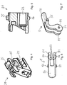
- the Figure 4 shows the cover part 21 in a perspective view.
- the bow-like or bridge-like shape of the form-locking element 25 can be seen.
- the Figure 5 shows the cover part 21 additionally in a lateral sectional view.
- lever catch elements 55 can be arranged on both sides of the manual grip area 50.
- the spring actuating elements 52 protrude toward the inside of the side cheeks 51, that is to say to the region surrounded by the side cheeks 51.
- the two spring actuation elements 52 can also be connected to form a continuous single spring actuation element.
- the actuating lever 5 can have laterally protruding bearing journals 56 in addition to the defined bearing and rotary guide. These journals 56 can engage in corresponding mounting holes in the main housing part 20. Alternatively, the actuating lever 5 can also be floating in the insulating housing 2. In this case, the journals 56 are not required.
- a further positive coupling between the cover part 21 and the main housing part 20 can be realized by side fixing elements 29.
- the main housing part has an upper side 80, a lower side 81 opposite the upper side 80 and a plurality of vertical walls 82, 83, 84 connecting the upper side 80 to the lower side 81.
- the vertical walls 82, 83 can be designed as side walls, which laterally limit the insulating material housing 2 to the outside.
- At least one intermediate wall can be present as a further vertical wall 84 in the interior of the insulating material housing 2.
- the enlarged detail of the Figure 10 illustrates one or more side fixing elements 29 can be arranged.
- the side fixing elements 29 can be positively connected to the respective side positive locking elements 85 of the cover part 21. In this way, bending or bending of a vertical wall 82, 83, 84 in particular can be prevented.
- Such a side fixing element 29 can be designed, for example, as a latching element, for example with a latching tongue and an end latching hook, such as in particular by the Figure 10 is made clear. Such a locking element can then engage behind an associated side form-locking element 85.
Landscapes
- Connections Arranged To Contact A Plurality Of Conductors (AREA)
- Details Of Connecting Devices For Male And Female Coupling (AREA)
Abstract
Description
- Die Erfindung betrifft eine Leiteranschlussklemme, die folgendes aufweist:
- a) wenigstens ein Isolierstoffgehäuse,
- b) wenigstens einen Kontakteinsatz, der zumindest überwiegend innerhalb des Isolierstoffgehäuses angeordnet ist und der wenigstens eine Klemmfeder aufweist,
- c) wenigstens einen als vom Isolierstoffgehäuse separates Bauteil ausgebildeten Betätigungshebel, durch den die Klemmfeder ausgelenkt werden kann, wobei der Betätigungshebel zumindest von einer geöffneten in eine geschlossene Stellung und umgekehrt verschwenkbar ist,
- d) wobei das Isolierstoffgehäuse als separate Bauteile wenigstens ein Hauptgehäuseteil und ein Deckelteil aufweist, das an dem Hauptgehäuseteil mittels wenigstens eines Formschlusselements formschlüssig fixierbar ist.
- Solche Leiteranschlussklemmen dienen zum Anklemmen wenigstens eines elektrischen Leiters an dem Kontakteinsatz durch Klemmung mittels der Klemmfeder. Eine derartige Leiteranschlussklemme ist beispielsweise aus der
DE 10 2014 102 517 A1 bekannt. Aus derDE 10 2010 060 252 B4 ist eine elektrische Anschlussbaueinheit bekannt. Aus derDE 20 2006 013 216 U1 ist eine Klemmvorrichtung für einen abisolierfreien Leiteranschluss bekannt. Weitere Leiteranschlussklemmen sind aus derDE 20 2014 011 234 U1 und derDE 10 2014 114 021 A1 bekannt. - Der Erfindung liegt die Aufgabe zugrunde, eine solche Leiteranschlussklemme hinsichtlich der mechanischen Robustheit weiter zu verbessern.
- Diese Aufgabe wird bei einer Leiteranschlussklemme der eingangs genannten Art dadurch gelöst, dass
- e) der Betätigungshebel wenigstens eine Haltekante aufweist und
- f) das Deckelteil zumindest bei geschlossenem Betätigungshebel mittels der wenigstens einen Haltekante gegen ein Lösen von dem Hauptgehäuseteil gesichert ist.
- Dies hat den Vorteil, dass der Betätigungshebel in die Versteifung und Stabilisierung des mechanischen Aufbaus der Leiteranschlussklemme, insbesondere des Isolierstoffgehäuses, eingebunden wird und somit außer der Funktion zur Betätigung der Klemmfeder eine zusätzliche Funktion aufweist, nämlich die Erhöhung der mechanischen Stabilität der Leiteranschlussklemme. Wenn auf das Deckelteil eine Zugkraft aufgebracht wird, zum Beispiel dadurch, dass von außen an dem am Kontakteinsatz angeklemmten elektrischen Leiter gezogen wird, so kann sich bei der vorliegenden Erfindung das Deckelteil zusätzlich zu anderen Fixierelementen, wie zum Beispiel der formschlüssigen Fixierung mittels des Formschlusselements, an der durch die Haltekante des Betätigungshebels bereit gestellten weiteren Fixierung abstützen und hierüber die Kräfte auf andere Teile des Isolierstoffgehäuses übertragen. Auf diese Weise kann einem Lösen oder Herausziehen des Deckelteils vom Hauptgehäuseteil wirkungsvoll entgegengewirkt werden. Im Ergebnis können hierdurch die maximal zulässigen Leiter-Auszugskräfte der Leiteranschlussklemme erhöht werden.
- Das wenigstens eine Formschlusselement dient zur Fixierung des Deckelteils am Hauptgehäuseteil. Ein solches Formschlusselement kann beispielsweise als Rastelement ausgebildet sein, sodass das Deckelteil mittels Verrastung durch dieses Formschlusselement beziehungsweise Rastelement am Gehäuseteil fixiert werden kann. Das wenigstens eine Formschlusselement kann integraler Bestandteil des Deckelteils sein, z.B. indem das wenigstens eine Formschlusselement einstückig mit dem Deckelteil ausgeformt ist. Das Deckelteil kann beispielsweise eine entsprechende Gegenkontur aufweisen, die mit der Haltekante zum Sichern des Deckelteils am Hauptgehäuseteil zusammen wirkt.
- Der Kontakteinsatz weist zumindest wenigstens eine Klemmfeder auf. Die Klemmfeder kann einen Anlageschenkel, einen sich an den Anlageschenkel anschließenden Federbogen und einen sich an den Federbogen anschließenden Klemmschenkel aufweisen. Der Klemmschenkel kann an seinem freien Ende mit einer Klemmkante enden, die zum Festklemmen des elektrischen Leiters dient. Der Anlageschenkel dient zur mechanischen Befestigung und Abstützung der Klemmfeder an wenigstens einem Teil der Leiteranschlussklemme, z.B. am Betätigungshebel, an einer Stromschiene und/oder an dem Isolierstoffgehäuse. Der Kontakteinsatz kann zusätzlich beispielsweise eine Stromschiene aufweisen, die mit der Klemmfeder gekoppelt ist. Die Stromschiene kann einen Leiterauflagebereich haben, an dem der anzuklemmende elektrische Leiter mittels der Klemmfeder gegen die Stromschiene gedrückt wird. Die Klemmstelle wird dann zwischen der Klemmkante des Klemmschenkels und dem Leiteranlagebereich der Stromschiene gebildet.
- Wie erwähnt, weist der Betätigungshebel zumindest eine geöffnete und eine geschlossene Stellung auf. Hierbei kann die geöffnete Stellung des Betätigungshebels mit einer geöffneten Klemmstelle korrespondieren, die geschlossene Stellung des Betätigungshebels kann mit einer geschlossenen Klemmstelle korrespondieren. Bei geschlossener Klemmstelle wird ein elektrischer Leiter mittels der Klemmfeder festgeklemmt, bei geöffneter Klemmstelle kann der elektrische Leiter im Wesentlichen ohne Kraftaufwand aus der Klemmstelle entfernt werden oder in die Klemmstelle eingeführt werden.
- Das Hauptgehäuseteil kann beispielsweise eine Aussparung oder Öffnung aufweisen, die dazu genutzt werden kann, den Kontakteinsatz im Hauptgehäuseteil anzuordnen. Um diese Aussparung oder Öffnung zumindest weitgehend zu verschließen, dient das Deckelteil, das beispielsweise ganz oder teilweise in die Aussparung oder Öffnung eingesetzt werden kann und darin fixiert werden kann. Um den anzuklemmenden elektrischen Leiter in das Isolierstoffgehäuse einführen zu können, weist das Isolierstoffgehäuse eine Leitereinführungsöffnung auf. Die Leitereinführungsöffnung kann am Hauptgehäuseteil oder am Deckelteil angeordnet sein. Das Deckelteil kann beispielsweise einen sich an die Leitereinführungsöffnung anschließenden Leitereinführungskanal aufweisen, durch den ein elektrischer Leiter gezielt zur Klemmstelle geführt werden kann.
- Gemäß einer vorteilhaften Ausgestaltung der Erfindung ist vorgesehen, dass das Deckelteil zumindest bei geschlossenem Betätigungshebel mittels der wenigstens einen Haltekante gegen ein Lösen von dem Hauptgehäuseteil dadurch gesichert ist, dass das wenigstens eine Formschlusselement des Deckelteils von der wenigstens einen Haltekante umgriffen ist. Auf diese Weise wird das Formschlusselement, das bereits zur Fixierung des Deckelteils am Hauptgehäuseteil dient, zusätzlich für die Fixierung zwischen dem Betätigungshebel und dem Deckelteil genutzt. Dementsprechend kann in dieser Ausführungsform die erwähnte Gegenkontur des Deckelteils durch das wenigstens eine Formschlusselement realisiert werden, zum Beispiel durch eine als Gegenstück zur Haltekante wirkende Fixierkante des Formschlusselements.
- Gemäß einer vorteilhaften Ausgestaltung der Erfindung ist vorgesehen, dass ein elektrischer Leiter am Kontakteinsatz mittels der Klemmfeder durch Federkraft fixierbar ist, wobei eine auf den elektrischen Leiter außerhalb der Leiteranschlussklemme ausgeübte Zugkraft auf den Kontakteinsatz und hiervon auf das Deckelteil und vom Deckelteil auf den Betätigungshebel übertragbar ist. Durch die auf diese Weise gebildete Kraftkette kann die auf den elektrischen Leiter ausgeübte Zugkraft wirkungsvoll auf den Betätigungshebel übertragen werden und damit zumindest teilweise vom Deckelteil abgeleitet werden.
- Gemäß einer vorteilhaften Ausgestaltung der Erfindung ist vorgesehen, dass die auf den elektrischen Leiter außerhalb der Leiteranschlussklemme ausgeübte Zugkraft vom Betätigungshebel auf das Hauptgehäuseteil übertragbar ist. Auf diese Weise kann die erwähnte Kraftkette fortgesetzt werden bis zum Hauptgehäuseteil, das heißt zu einer Stelle, an der der Betätigungshebel wiederum am Hauptgehäuseteil befestigt und/oder gelagert ist.
- Gemäß einer vorteilhaften Ausgestaltung der Erfindung ist vorgesehen, dass der Betätigungshebel einen Federbetätigungsbereich, an dem wenigstens ein Federbetätigungselement zur Auslenkung der Klemmfeder angeordnet ist, und einen manuellen Griffbereich aufweist, an dem der Betätigungshebel manuell zu betätigen ist, wobei die Haltekante in dem manuellen Griffbereich angeordnet ist. Auf diese Weise kann die Haltekante an einer geeigneten Stelle am Betätigungshebel angeordnet werden, ohne dass die den Betätigungsmechanismus der Klemmfeder betreffenden Bereiche des Betätigungshebels davon betroffen sind oder ggf. umgestaltet werden müssen.
- Gemäß einer vorteilhaften Ausgestaltung der Erfindung ist vorgesehen, dass der Betätigungshebel an seiner zum Deckelteil weisenden Seite wenigstens eine Ausnehmung aufweist, an der die Haltekante angeordnet ist. Auf diese Weise kann die Ausnehmung mit der Haltekante sozusagen an der Innenseite des Betätigungshebels und insbesondere an der Innenseite des manuellen Betätigungsbereichs angeordnet werden. Auf diese Weise kann die Fixierung des Deckelteils mittels des Betätigungshebels besonders effizient gestaltet werden. Zudem ist diese Fixierung nicht störend für die manuelle Betätigung des Betätigungshebels und das optische Erscheinungsbild der Leiteranschlussklemme. Die Ausnehmung kann insbesondere nach Art eines Sacklochs ausgebildet sein, das heißt als Ausnehmung, die den Betätigungshebel beziehungsweise den manuellen Betätigungsbereich nicht vollständig durchdringt.
- Gemäß einer vorteilhaften Ausgestaltung der Erfindung ist vorgesehen, dass ein aus dem Hauptgehäuseteil herausragender Bereich des Formschlusselements des Deckelteils im geschlossenen Zustand des Betätigungshebels in die Ausnehmung hineinragt. Auf diese Weise kann eine formschlüssige Fixierung zwischen der in der Ausnehmung angeordneten Haltekante und dem Formschlusselement des Deckelteils auf einfache Weise realisiert werden.
- Gemäß einer vorteilhaften Ausgestaltung der Erfindung ist vorgesehen, dass der Betätigungshebel zumindest in der geschlossenen Stellung am Hauptgehäuseteil rastend fixierbar ist. Hierdurch kann sichergestellt werden, dass der Betätigungshebel in definierter Weise in der geschlossenen Stellung verharrt, auch wenn die Leiteranschlussklemme beispielsweise durch Vibration oder ähnliche äußere Einflüsse belastet wird. Die rastende Fixierung des Betätigungshebels am Hauptgehäuseteil kann beispielsweise dadurch realisiert werden, dass das Hauptgehäuseteil wenigstens ein Gehäuserastelement aufweist, das zum Zusammenwirken mit wenigstens einem am Betätigungshebel angeordneten Hebelrastelement ausgebildet ist. Hierdurch kann der Betätigungshebel zumindest in der geschlossenen Stellung durch Zusammenwirken des Hebelrastelements mit dem Gehäuserastelement rastend fixiert werden. Ferner kann durch das Zusammenwirken des Hebelrastelements mit dem Gehäuserastelement auf einfache Art und Weise eine Übertragung der auf den elektrischen Leiter außerhalb der der Leiteranschlussklemme ausgeübten Zugkraft von dem Betätigungshebel auf das Hauptgehäuseteil sichergestellt werden.
- Das Hebelrastelement kann zum Beispiel als einer oder zwei an gegenüberliegenden Seiten seitlich vom manuellen Betätigungsbereich abragende Rastzapfen ausgebildet sein. Das Gehäuserastelement kann als dem jeweiligen Hebelrastelement zugeordnete Rastaussparung in einer Seitenwand des Hauptgehäuseteils ausgebildet sein. Die Rastzapfen können dann in die Rastaussparungen des Hauptgehäuseteils eingreifen.
- Gemäß einer vorteilhaften Ausgestaltung der Erfindung ist vorgesehen, dass das Hauptgehäuseteil eine federnde Rastzunge aufweist, die bei am Hauptgehäuseteil befestigtem Deckelteil das Formschlusselement des Deckelteils untergreift und mit einer Rastkante hintergreift. Dies ermöglicht eine zuverlässige Fixierung des Deckelteils am Hauptgehäuseteil. So kann beispielsweise das Hauptgehäuseteil auf der dem Betätigungshebel zugewandten Seite eine parallel zur Leitereinsteckrichtung vorstehende Rastzunge mit einem endseitigen Rasthaken aufweisen. In diesem Fall kann das Formschlusselement des Deckelteils beispielsweise als bügelförmige Haltelasche ausgebildet sein, die durch die Rastzunge mit dessen endseitigem Rasthaken rastend unter- und hintergriffen wird. Die Rastkante ist somit am endseitigen Rasthaken ausgebildet.
- Gemäß einer vorteilhaften Ausgestaltung der Erfindung ist vorgesehen, dass das Deckelteil an der dem Formschlusselement abgewandten Seite ein weiteres Formschlusselement aufweist, dass zur formschlüssigen Verbindung mit einem Haltelement des Hauptgehäuseteils eingerichtet ist. Auf diese Weise kann das Deckelteil an zumindest zwei voneinander beabstandeten Stellen formschlüssig mit dem Hauptgehäuseteil verbunden werden.
- Gemäß einer vorteilhaften Ausgestaltung der Erfindung ist vorgesehen, dass das Hauptgehäuseteil eine Oberseite, an der der Betätigungshebel zumindest in der geöffneten Stellung aus dem Hauptgehäuseteil herausragt, und eine der Oberseite gegenüberliegende Unterseite aufweist, wobei das Hauptgehäuseteil mehrere die Oberseite mit der Unterseite verbindende Vertikalwände aufweist, wobei an wenigstens einer Vertikalwand ein Seitenfixierelement angeordnet ist, durch das das Deckelteil seitlich durch Formschluss an dem Hauptgehäuseteil fixierbar ist. Hierdurch wird eine zusätzliche formschlüssige Fixierung zwischen dem Hauptgehäuseteil und dem Deckelteil realisiert. Dies ermöglicht es beispielsweise, die Vertikalwände zusätzlich zu stabilisieren und gegenüber einem Herausbiegen oder Wegbiegen zusichern.
- Hierzu kann am Deckelteil ein dem Seitenfixierelement zugeordnetes Seitenformschlusselement angeordnet sein, mit dem bei am Hauptgehäuseteil befestigtem Deckelteil die formschlüssige Verbindung zum Seitenfixierelement hergestellt wird. Die formschlüssige Verbindung kann beispielsweise als Rastverbindung ausgebildet sein, in diesem Fall kann das Seitenfixierelement als Rastelement ausgebildet sein, zum Beispiel mit einer parallel zur Leitereinsteckrichtung ausgerichteten Rastzunge mit einem endseitigen Rasthaken. Weitere Realisierungsmöglichkeiten für das Seitenfixierelement ist die Ausbildung als Rastzapfen und/oder mit einer Schwalbenschwanz-Geometrie.
- Die Vertikalwände können insbesondere als Seitenwände des Hauptgehäuseteils ausgebildet sein, das heißt als seitliche Wände, die das Hauptgehäuseteil nach außen hin begrenzen. Ist die Leiteranschlussklemme als mehrpolige Leiteranschlussklemme ausgebildet, die mehrere voneinander getrennte Leiteranschlusskammern aufweist, so können durch das Isolierstoffgehäuse außer den Seitenwänden auch innenliegende Zwischenwände gebildet sein, durch die weitere Vertikalwände realisiert werden. Auch an solchen Zwischenwänden können die erwähnten Seitenfixierelemente realisiert sein.
- Die zuvor erläuterte Ausgestaltung der erfindungsgemäßen Leiteranschlussklemme ist zudem als eigenständige Erfindung anzusehen. Die Erfindung betrifft daher auch eine Leiteranschlussklemme, die folgendes aufweist:
- a) wenigstens ein Isolierstoffgehäuse, das wenigstens eine Leitereinführungsöffnung zum Einführen eines elektrischen Leiters in das Isolierstoffgehäuse aufweist,
- b) wenigstens einen Kontakteinsatz, der zumindest überwiegend innerhalb des Isolierstoffgehäuses angeordnet ist und der wenigstens eine Klemmfeder aufweist,
- c) wenigstens einen Betätigungshebel, durch den die Klemmfeder ausgelenkt werden kann, wobei der Betätigungshebel zumindest von einer geöffneten in eine geschlossene Stellung und umgekehrt verschwenkbar ist,
- d) wobei das Isolierstoffgehäuse als separate Bauteile wenigstens ein Hauptgehäuseteil und ein Deckelteil aufweist, das an dem Hauptgehäuseteil mittels wenigstens eines Formschlusselements formschlüssig fixierbar ist,
- Im Sinne der vorliegenden Erfindung ist unter dem unbestimmten Begriff "ein" kein Zahlwort zu verstehen. Wenn also z.B. von einem Bauteil die Rede ist, so ist dies im Sinne von "mindestens einem Bauteil" zu interpretieren. Soweit Winkelangaben in Grad gemacht werden, beziehen sich diese auf ein Kreismaß von 360 Grad (360°).
- Die Erfindung wird nachfolgend anhand von Ausführungsbeispielen unter Verwendung von Zeichnungen näher erläutert.
- Es zeigen:
- Figur 1
- - eine Leiteranschlussklemme in Draufsicht und
- Figur 2
- - die Leiteranschlussklemme gemäß
Figur 1 in der dort markierten Schnittebene B-B und - Figur 3
- - die Leiteranschlussklemme gemäß
Figur 1 in der dort markierten Schnittebene A-A und - Figur 4
- - ein Deckelteil in perspektivischer Ansicht und
- Figur 5
- - das Deckelteil gemäß
Figur 4 in seitlicher Schnittansicht und - Figur 6
- - einen Betätigungshebel in Draufsicht und
- Figur 7
- - den Betätigungshebel gemäß
Figur 6 in perspektivischer Ansicht und - Figur 8
- - die Leiteranschlussklemme gemäß
Figur 1 in Seitenansicht und - Figur 9
- - die Leiteranschlussklemme gemäß
Figur 8 in der dort markierten Schnittebene C-C und - Figur 10
- - eine Ausschnittsvergrößerung aus
Figur 9 . - Die in den Zeichnungen verwendeten Bezugszeichen haben folgende Zuordnung:
- 1
- Leiteranschlussklemme
- 2
- Isolierstoffgehäuse
- 3
- Stromschiene
- 4
- Klemmfeder
- 5
- Betätigungshebel
- 6
- Steckverbinderbereich
- 7
- Leiteranschlussbereich
- 20
- Hauptgehäuseteil
- 21
- Deckelteil
- 22
- Leitereinführungsöffnung
- 23
- Rastzunge
- 24
- Rastkante
- 25
- Formschlusselement
- 26
- weiteres Formschlusselement
- 27
- Halteelement
- 28
- Gehäuserastelement
- 29
- Seitenfixierelement
- 30
- Leiteranschlussbereich
- 40
- Anlageschenkel
- 41
- Federbogen
- 42
- Klemmschenkel
- 43
- Klemmkante
- 50
- Griffbereich
- 51
- Seitenwange
- 52
- Federbetätigungselement
- 53
- Ausnehmung
- 54
- Haltekante
- 55
- Hebelrastelement
- 56
- Lagerzapfen
- 60
- Steckkontakt-Einführungsöffnung
- 61
- Kontaktgabel
- 62
- Kontaktgabel
- 63
- Verbindungsabschnitt
- 80
- Oberseite
- 81
- Unterseite
- 82
- Vertikalwand
- 83
- Vertikalwand
- 84
- Vertikalwand
- 85
- Seitenformschlusselement
- Die
Figur 1 zeigt zunächst die hauptsächlichen Komponenten der Leiteranschlussklemme 1. Die Leiteranschlussklemme 1 ist im dargestellten Ausführungsbeispiel als zweipoliger Steckverbinder ausgebildet. Hierzu weist die Leiteranschlussklemme 1 einen Steckverbinderbereich 6 und einen Leiteranschlussbereich 7 auf. Die Leiteranschlussklemme 1 weist ein Isolierstoffgehäuse 2 auf, dass sich über den Steckverbinderbereich 6 und den Leiteranschlussbereich 7 erstreckt. Die Leiteranschlussklemme 1 weist zudem für jeden der zwei im Isolierstoffgehäuse 2 angeordneten Kontakteinsätze (wie nachfolgend noch erläutert) jeweils einen Betätigungshebel 5 auf. Der Betätigungshebel 5 ist im oberen Bereich derFigur 1 in der geschlossenen Stellung wiedergegeben, im unteren Bereich in der geöffneten Stellung. In derFigur 1 sind zudem zwei Schnittlinien A-A und B-B eingezeichnet, anhand derer unter Verwendung derFiguren 2 und3 der innere Aufbau der Leiteranschlussklemme 1 erläutert werden soll. Die Leiteranschlussklemme 1 ist in beiden Bereichen, das heißt im Bereich der Schnittlinie B-B und der Schnittlinie A-A gleich aufgebaut, sodass die Ausführungen für beide Bereiche gelten. Es ist zu beachten, dass die Schnittlinie A-A etwa in der Mitte des Leiteranschlussbereichs 7 einen vertikalen Versatz aufweist, sodass die Schnittlinie A-A nicht eine durchgehende Schnittebene widergibt. - Die
Figur 2 zeigt den Schnitt entsprechend der Schnittlinie B-B. Hierdurch wird deutlich, dass das Isolierstoffgehäuse 2 zumindest zweiteilig ausgebildet ist, und zwar mit einem Hauptgehäuseteil 20 und einem Deckelteil 21, dass in einer Aussparung des Hauptgehäuseteils 20 eingesetzt ist und darin formschlüssig befestigt ist. Im Inneren des Isolierstoffgehäuses 2 befindet sich im Leiteranschlussbereich 7 ein Kontakteinsatz, der eine Klemmfeder 4 und eine Stromschiene 3 aufweist. Die Klemmfeder 4 weist einen Anlageschenkel 40, eine sich an den Anlageschenkel 40 anschließenden Federbogen 41 und einen sich an den Federbogen 41 anschließenden Klemmschenkel 42 auf. Der Klemmschenkel 42 weist an seinem freien Ende eine Klemmkante 43 auf. Die Stromschiene 3 weist einen Leiteranschlussbereich 30 auf, in dem zum Beispiel eine Sicke angeformt sein kann. Ein elektrischer Leiter kann an einer zwischen der Klemmkante 43 und dem Leiteranschlussbereich 30 gebildeten Klemmstelle festgeklemmt werden. Der elektrische Leiter kann durch eine Leitereinführungsöffnung 22 in das Isolierstoffgehäuse 2 eingeführt werden. Die Leitereinführungsöffnung 22 kann in dem Deckelteil 21 angeordnet sein. - In dem Steckverbinderbereich 6 weist die Leiteranschlussklemme 1 einen Steckkontakt auf, der in diesem Ausführungsbeispiel als ein als Gabelkontakt ausgebildeter Buchsenkontakt mit einander gegenüberliegenden Kontaktschenkeln 61, 62 gebildet ist. Die Kontaktgabeln 61, 62 sind über einen vertikal verlaufenden Verbindungsabschnitt 63 miteinander verbunden. Die Stromschiene 3 kann einstückig in Form eines Metallteils mit den Kontaktschenkeln 61, 62 und dem Verbindungsabschnitt 63 ausgebildet sein. Das Isolierstoffgehäuse 2 weist am Ende des Steckverbinderbereichs 6 eine Steckkontakt-Einführungsöffnung 60 auf. Durch diese Steckkontakt-Einführungsöffnung 60 kann ein Kontaktstift oder ein Kontaktmesser eingeführt werden und zwischen den Kontaktschenkeln 61, 62 festgeklemmt werden. Die Anordnung von Buchsenkontakt und Kontaktstift bzw. Kontaktmesser kann alternativ auch vertauscht vorgesehen werden.
- Die Leiteranschlussklemme 1 weist außerdem einen Betätigungshebel 5 auf, der zur Betätigung des Klemmschenkels 42 der Klemmfeder 4 dient. Hierzu weist der Betätigungshebel 5 seitlich an Seitenwangen 51 des Betätigungshebels 5 angeordnete Federbetätigungselemente 52 auf, die z.B. als Betätigungsnocken ausgebildet sein können. Wird der Betätigungshebel 5 von der in der
Figur 2 dargestellten geschlossenen Stellung in die geöffnete Stellung verschwenkt, so wird der Klemmschenkel 42 mittels der Federbetätigungselemente 52 mitbewegt und hierbei insbesondere von der Stromschiene 3 fortbewegt, sodass die Klemmstelle geöffnet wird. - Der Betätigungshebel 5 erstreckt sich von den Seitenwangen 51 weiter zu einem manuellen Griffbereich 50 hin, an dem der Betätigungshebel 5 manuell betätigt werden kann. Wie erkennbar ist, kann der manuelle Griffbereich 50 über die Außenkontur des Isolierstoffgehäuses 2 hinausragen, sodass er auch in der geschlossenen Stellung leicht gegriffen und aus der geschlossenen Stellung fortbewegt werden kann.
- Das Deckelteil 21 ist formschlüssig an dem Hauptgehäuseteil 20 befestigt. Hierzu weist das Deckelteil 21 ein Formschlusselement 25 auf, das von einer Rastzunge 23 des Hauptgehäuseteils 20 untergriffen und hintergriffen ist. Die Rastzunge 23 weist insbesondere eine Rastkante 24 auf, mit der das Formschlusselement 25 hintergriffen ist. Auf der gegenüberliegenden Seite weist das Deckelteil 21 ein weiteres Formschlusselement 26 auf, zum Beispiel eine Rastnase, mit dem das Deckelteil 21 zusätzlich mit dem Hauptgehäuseteil 20, und zwar mit einem Halteelement 27 des Hauptgehäuseteils 20, formschlüssig verbunden ist. Das Halteelement 27 kann zum Beispiel als Rastaussparung ausgebildet sein.
- Eine zusätzliche mechanische Fixierung des Deckelteils 21 wird dadurch realisiert, dass der Betätigungshebel 5 eine Haltekante 54 aufweist, zum Beispiel eine am manuellen Griffbereich 50 angeordnete Haltekante 54, die mit dem Formschlusselement 25 des Deckelteils 21 zusammenwirkt und dieses zumindest in der geschlossenen Stellung des Betätigungshebels 5 hintergreift.
- Die
Figur 3 zeigt die Leiteranschlussklemme 1 in der Schnittlinie A-A. In dieser Ansicht sind beide inFigur 1 dargestellten Betätigungshebel 5 erkennbar, das heißt der eine in der geschlossenen Stellung angeordnete Betätigungshebel und der andere in der geöffneten Stellung dargestellte Betätigungshebel. Hierdurch wird insbesondere verdeutlich, dass der Betätigungshebel 5 eine sacklochartige Aussparung 53 auf der Unterseite aufweisen kann, an der die Haltekante 54 ausgebildet ist. - In der
Figur 3 ist eine weitere Fixierung des Betätigungshebels 5 am Isolierstoffgehäuse 2, insbesondere am Hauptgehäuseteil 21, erkennbar. Der Betätigungshebel 5 kann, insbesondere am manuellen Griffbereich 50, an einer oder an beiden Seiten seitlich abragende Hebelrastelemente 55 aufweisen, z.B. in Form von Rastzapfen. Diese Hebelrastelemente 55 können mit Gehäuserastelementen, die am Hauptgehäuseteil 20 ausgebildet sind, zur rastenden Fixierung des Betätigungshebels 5 zusammenwirken. Die Gehäuserastelemente 28 können z.B. als Rastaussparungen ausgebildet sein. Dementsprechend können die Rastzapfen in die Rastaussparungen des Hauptgehäuseteils 20 eingreifen, wenn der Betätigungshebel 5 in der geschlossenen Stellung ist. - Die
Figur 4 zeigt das Deckelteil 21 in perspektivischer Darstellung. Erkennbar ist insbesondere die bügelartige oder brückenartige Form des Formschlusselements 25. Unterhalb des Formschlusselements 25 befindet sich ein Freiraum, durch die die Rastzunge 23 des Hauptgehäuseteils 20 gesteckt werden kann. - Die
Figur 5 zeigt das Deckelteil 21 zusätzlich in seitlicher Schnittdarstellung. - Wie aus der
Figur 6 deutlich wird, können die Hebelrastelemente 55 an beiden Seiten des manuellen Griffbereichs 50 angeordnet sein. - Erkennbar ist ferner, dass die Federbetätigungselemente 52 zur Innenseite der Seitenwangen 51 abragen, das heißt zu dem von den Seitenwangen 51 umgebenen Bereich. Alternativ können die beiden Federbetätigungselemente 52 auch zu einem durchgehenden einzelnen Federbetätigungselement verbunden sein. Der Betätigungshebel 5 kann zusätzlich zur definierten Lagerung und Drehführung seitlich abragende Lagerzapfen 56 aufweisen. Diese Lagerzapfen 56 können in entsprechende Lagerungslöcher des Hauptgehäuseteils 20 eingreifen. Alternativ kann der Betätigungshebel 5 auch schwimmend im Isolierstoffgehäuse 2 gelagert sein. In diesem Fall sind die Lagerzapfen 56 nicht erforderlich.
- Wie durch die
Figuren 8 bis 10 verdeutlich wird, kann eine weitere formschlüssige Kopplung zwischen dem Deckelteil 21 und dem Hauptgehäuseteil 20 durch Seitenfixierelemente 29 realisiert werden. Es sei zunächst davon ausgegangen, dass das Hauptgehäuseteil eine Oberseite 80, eine der Oberseite 80 gegenüberliegende Unterseite 81 und mehrere die Oberseite 80 mit der Unterseite 81 verbindende Vertikalwände 82, 83, 84 aufweist. Hierbei können die Vertikalwände 82, 83 als Seitenwände ausgebildet sein, die das Isolierstoffgehäuse 2 nach außen hin seitlich begrenzen. Im Inneren des Isolierstoffgehäuses 2 kann zumindest eine Zwischenwand als weitere Vertikalwand 84 vorhanden sein. An einer oder mehreren dieser Vertikalwände 82, 83, 84, können wie die Ausschnittsvergrößerung derFigur 10 verdeutlicht, jeweils eines oder mehrere Seitenfixierelemente 29 angeordnet sein. Die Seitenfixierelemente 29 können mit jeweiligen Seitenformschlusselementen 85 des Deckelteils 21 formschlüssig verbunden sein. Auf diese Weise kann insbesondere ein Aufbiegen oder Verbiegen einer Vertikalwand 82, 83, 84 verhindert werden. - Ein solches Seitenfixierelement 29 kann zum Beispiel als Rastelement ausgebildet sein, beispielsweise mit einer Rastzunge und einem endseitigen Rasthaken, wie insbesondere durch die
Figur 10 verdeutlicht wird. Ein solches Rastelement kann dann ein zugeordnetes Seitenformschlusselement 85 hintergreifen.
Claims (14)
- Leiteranschlussklemme (1), die folgendes aufweist:a) wenigstens ein Isolierstoffgehäuse (2),b) wenigstens einen Kontakteinsatz (3, 4), der zumindest überwiegend innerhalb des Isolierstoffgehäuses (2) angeordnet ist und der wenigstens eine Klemmfeder (4) aufweist,c) wenigstens einen als vom Isolierstoffgehäuse (2) separates Bauteil ausgebildeten Betätigungshebel (5), durch den die Klemmfeder (4) ausgelenkt werden kann, wobei der Betätigungshebel (5) zumindest von einer geöffneten in eine geschlossene Stellung und umgekehrt verschwenkbar ist,d) wobei das Isolierstoffgehäuse (2) als separate Bauteile wenigstens ein Hauptgehäuseteil (20) und ein Deckelteil (21) aufweist, das an dem Hauptgehäuseteil (20) mittels wenigstens eines Formschlusselements (25) formschlüssig fixierbar ist,dadurch gekennzeichnet, dasse) der Betätigungshebel (5) wenigstens eine Haltekante (54) aufweist undf) das Deckelteil (21) zumindest bei geschlossenem Betätigungshebel (5) mittels der wenigstens einen Haltekante (54) gegen ein Lösen von dem Hauptgehäuseteil (20) gesichert ist.
- Leiteranschlussklemme (1) nach Anspruch 1, dadurch gekennzeichnet, dass das wenigstens eine Formschlusselement (25) des Deckelteils (21) von der wenigstens einen Haltekante (54) übergriffen oder umgriffen ist.
- Leiteranschlussklemme (1) nach einem der vorhergehenden Ansprüche,
dadurch gekennzeichnet, dass ein elektrischer Leiter am Kontakteinsatz (3, 4) mittels der Klemmfeder (4) durch Federkraft fixierbar ist, wobei eine auf den elektrischen Leiter außerhalb der Leiteranschlussklemme (1) ausgeübte Zugkraft auf den Kontakteinsatz (3, 4) und hiervon auf das Deckelteil (21) und vom Deckelteil (21) auf den Betätigungshebel (5) übertragbar ist. - Leiteranschlussklemme (1) nach Anspruch 3, dadurch gekennzeichnet, dass die auf den elektrischen Leiter außerhalb der Leiteranschlussklemme (1) ausgeübte Zugkraft vom Betätigungshebel (5) auf das Hauptgehäuseteil (20) übertragbar ist.
- Leiteranschlussklemme (1) nach einem der vorhergehenden Ansprüche,
dadurch gekennzeichnet, dass der Betätigungshebel (5) einen Federbetätigungsbereich, an dem wenigstens ein Federbetätigungselement (52) zur Auslenkung der Klemmfeder (4) angeordnet ist, und einen manuellen Griffbereich (50) aufweist, an dem der Betätigungshebel (5) manuell zu betätigen ist, wobei die Haltekante (54) in dem manuellen Griffbereich (50) angeordnet ist. - Leiteranschlussklemme (1) nach einem der vorhergehenden Ansprüche,
dadurch gekennzeichnet, dass der Betätigungshebel (5) an seiner zum Deckelteil (21) weisenden Seite wenigstens eine Ausnehmung (53) aufweist, an der die Haltekante (54) angeordnet ist. - Leiteranschlussklemme (1) nach Anspruch 6, dadurch gekennzeichnet, dass ein aus dem Hauptgehäuseteil (20) herausragender Bereich des Formschlusselements (25) des Deckelteils (21) im geschlossenen Zustand des Betätigungshebels (5) in die Ausnehmung (53) hineinragt.
- Leiteranschlussklemme (1) nach einem der vorhergehenden Ansprüche,
dadurch gekennzeichnet, dass der Betätigungshebel (5) zumindest in der geschlossenen Stellung am Hauptgehäuseteil (20) rastend fixierbar ist. - Leiteranschlussklemme nach Anspruch 8, dadurch gekennzeichnet, dass zumindest ein vom Betätigungshebel (5) abragendes Hebelrastelement (55) in der geschlossenen Stellung des Betätigungshebels (5) mit einem am Hauptgehäuseteil (20) ausgebildeten Gehäuserastelement (28) zusammenwirkt.
- Leiteranschlussklemme nach Anspruch 9, dadurch gekennzeichnet, dass das das Gehäuserastelement (28) als eine Rastaussparung ausgebildet ist, in welche in der geschlossenen Stellung des Betätigungshebels (5) das als ein Rastzapfen ausgebildete Hebelrastelement (55) eingreift.
- Leiteranschlussklemme (1) nach einem der vorhergehenden Ansprüche,
dadurch gekennzeichnet, dass das Hauptgehäuseteil (20) eine federnde Rastzunge (23) aufweist, die bei am Hauptgehäuseteil (20) befestigtem Deckelteil (21) das Formschlusselement (25) des Deckelteils (21) untergreift und mit einer Rastkante (24) hintergreift. - Leiteranschlussklemme (1) nach einem der vorhergehenden Ansprüche,
dadurch gekennzeichnet, dass das Deckelteil (21) an der dem Formschlusselement (25) abgewandten Seite ein weiteres Formschlusselement (26) aufweist, dass zur formschlüssigen Verbindung mit einem Haltelement (27) des Hauptgehäuseteils (20) eingerichtet ist. - Leiteranschlussklemme (1) nach einem der vorhergehenden Ansprüche,
dadurch gekennzeichnet, dass das Hauptgehäuseteil (20) eine Oberseite (80), an der der Betätigungshebel (5) zumindest in der geöffneten Stellung aus dem Hauptgehäuseteil (20) herausragt, und eine der Oberseite (80) gegenüberliegende Unterseite (81) aufweist, wobei das Hauptgehäuseteil (20) mehrere die Oberseite (80) mit der Unterseite (81) verbindende Vertikalwände (82, 83, 84) aufweist, wobei an wenigstens einer Vertikalwand (82, 83, 84) ein Seitenfixierelement (29) angeordnet ist, durch das das Deckelteil (21) seitlich durch Formschluss an dem Hauptgehäuseteil (20) fixierbar ist. - Leiteranschlussklemme (1), die folgendes aufweist:a) wenigstens ein Isolierstoffgehäuse (2), das wenigstens eine Leitereinführungsöffnung (22) zum Einführen eines elektrischen Leiters in das Isolierstoffgehäuse (2) aufweist,b) wenigstens einen Kontakteinsatz (3, 4), der zumindest überwiegend innerhalb des Isolierstoffgehäuses (2) angeordnet ist und der wenigstens eine Klemmfeder (4) aufweist,c) wenigstens einen Betätigungshebel (5), durch den die Klemmfeder (4) ausgelenkt werden kann, wobei der Betätigungshebel (5) zumindest von einer geöffneten in eine geschlossene Stellung und umgekehrt verschwenkbar ist,d) wobei das Isolierstoffgehäuse (2) als separate Bauteile wenigstens ein Hauptgehäuseteil (20) und ein Deckelteil (21) aufweist, das an dem Hauptgehäuseteil (20) mittels wenigstens eines Formschlusselements (25) formschlüssig fixierbar ist,wobei das Hauptgehäuseteil (20) eine Oberseite (80), an der der Betätigungshebel (5) zumindest in der geöffneten Stellung aus dem Hauptgehäuseteil (20) herausragt, und eine der Oberseite (80) gegenüberliegende Unterseite (81) aufweist, wobei das Hauptgehäuseteil (20) mehrere die Oberseite (80) mit der Unterseite (81) verbindende Vertikalwände (82, 83, 84) aufweist, wobei an wenigstens einer Vertikalwand (82, 83, 84) ein Seitenfixierelement (29) angeordnet ist, durch das das Deckelteil (21) seitlich durch Formschluss an dem Hauptgehäuseteil (20) fixierbar ist, dadurch gekennzeichnet, dass das Deckelteil (21) die wenigstens eine Leitereinführungsöffnung (22) aufweist.
Priority Applications (1)
| Application Number | Priority Date | Filing Date | Title |
|---|---|---|---|
| EP22159986.3A EP4071935B1 (de) | 2018-12-11 | 2019-12-06 | Leiteranschlussklemme |
Applications Claiming Priority (1)
| Application Number | Priority Date | Filing Date | Title |
|---|---|---|---|
| DE102018131794.8A DE102018131794B4 (de) | 2018-12-11 | 2018-12-11 | Leiteranschlussklemme |
Related Child Applications (2)
| Application Number | Title | Priority Date | Filing Date |
|---|---|---|---|
| EP22159986.3A Division EP4071935B1 (de) | 2018-12-11 | 2019-12-06 | Leiteranschlussklemme |
| EP22159986.3A Division-Into EP4071935B1 (de) | 2018-12-11 | 2019-12-06 | Leiteranschlussklemme |
Publications (2)
| Publication Number | Publication Date |
|---|---|
| EP3667825A1 true EP3667825A1 (de) | 2020-06-17 |
| EP3667825B1 EP3667825B1 (de) | 2022-07-13 |
Family
ID=68834980
Family Applications (2)
| Application Number | Title | Priority Date | Filing Date |
|---|---|---|---|
| EP19214200.8A Active EP3667825B1 (de) | 2018-12-11 | 2019-12-06 | Leiteranschlussklemme |
| EP22159986.3A Active EP4071935B1 (de) | 2018-12-11 | 2019-12-06 | Leiteranschlussklemme |
Family Applications After (1)
| Application Number | Title | Priority Date | Filing Date |
|---|---|---|---|
| EP22159986.3A Active EP4071935B1 (de) | 2018-12-11 | 2019-12-06 | Leiteranschlussklemme |
Country Status (5)
| Country | Link |
|---|---|
| US (1) | US10892578B2 (de) |
| EP (2) | EP3667825B1 (de) |
| JP (1) | JP7469870B2 (de) |
| CN (1) | CN111313161B (de) |
| DE (1) | DE102018131794B4 (de) |
Cited By (1)
| Publication number | Priority date | Publication date | Assignee | Title |
|---|---|---|---|---|
| US12176651B2 (en) | 2020-06-18 | 2024-12-24 | Ideal Industries, Inc. | Conductor terminal |
Families Citing this family (4)
| Publication number | Priority date | Publication date | Assignee | Title |
|---|---|---|---|---|
| USD929343S1 (en) * | 2019-06-27 | 2021-08-31 | Jiangmen Krealux Electric Appliances Co., Ltd. | Terminal block |
| USD937219S1 (en) * | 2019-06-27 | 2021-11-30 | Jiangmen Krealux Electrical Appliances Co., Ltd. | Wire connector for terminal block |
| JP6897847B1 (ja) | 2020-06-02 | 2021-07-07 | 三菱マテリアル株式会社 | 絶縁樹脂回路基板の製造方法 |
| DE102021112960A1 (de) * | 2021-05-19 | 2022-11-24 | WAGO Verwaltungsgesellschaft mit beschränkter Haftung | Leiteranschlussklemme mit wenigstens einem Federkraftklemmanschluss |
Citations (9)
| Publication number | Priority date | Publication date | Assignee | Title |
|---|---|---|---|---|
| DE3743410A1 (de) * | 1987-12-21 | 1989-06-29 | Electro Terminal Gmbh | Schraubenlose verbindungsklemme |
| DE202006013216U1 (de) | 2005-08-29 | 2006-11-16 | Phoenix Contact Gmbh & Co. Kg | Klemmvorrichtung für abisolierfreien Leiteranschluß |
| EP2445056A1 (de) * | 2010-10-19 | 2012-04-25 | Wago Verwaltungsgesellschaft mbH | Elektrische Verbindungsklemme |
| DE102010060252B4 (de) | 2010-10-29 | 2015-02-12 | Phoenix Contact Gmbh & Co. Kg | Elektrische Anschlussbaueinheit |
| DE102014102517A1 (de) | 2014-02-26 | 2015-08-27 | Wago Verwaltungsgesellschaft Mbh | Verbindungsklemme und Federkraftklemmkontakt hierzu |
| DE102014114021A1 (de) | 2014-09-26 | 2016-03-31 | Obrist Technologies Gmbh | Batteriegehäuse |
| DE102014114026A1 (de) * | 2014-09-26 | 2016-03-31 | Wago Verwaltungsgesellschaft Mbh | Leiteranschlussklemme und Verfahren zu deren Montage |
| DE202014011234U1 (de) | 2013-02-13 | 2018-09-17 | WAGO Verwaltungsgesellschaft mit beschränkter Haftung | Leiteranschlussklemme |
| EP3595090A1 (de) * | 2018-07-10 | 2020-01-15 | Wago Verwaltungsgesellschaft mbH | Leiteranschlussklemme |
Family Cites Families (18)
| Publication number | Priority date | Publication date | Assignee | Title |
|---|---|---|---|---|
| JP2736500B2 (ja) * | 1993-07-06 | 1998-04-02 | 株式会社 ニチフ端子工業 | 電線接続器 |
| DE9415076U1 (de) * | 1994-09-16 | 1995-10-12 | Siemens AG, 80333 München | Elektronisches Gerät, insbesondere Automatisierungsgerät |
| ES1047527Y (es) * | 2000-11-03 | 2001-09-01 | Codina M Cristina Moret | Bloque para embornado de terminales de conductores. |
| FR2829878A1 (fr) * | 2001-09-20 | 2003-03-21 | Entrelec | Dispositif de raccordement a ressort de connexion manoeuvre par une came |
| ES2414830T3 (es) * | 2008-08-27 | 2013-07-22 | Phoenix Contact Gmbh & Co. Kg | Borna de conexión eléctrica |
| US7785134B2 (en) * | 2008-12-30 | 2010-08-31 | General Electric Company | Contact terminal for conductors |
| JP5821003B2 (ja) | 2010-08-26 | 2015-11-24 | パナソニックIpマネジメント株式会社 | 配線器具 |
| DE102011056410B4 (de) | 2011-12-14 | 2013-06-27 | Wago Verwaltungsgesellschaft Mbh | Anschlussklemme |
| TW201507300A (zh) * | 2013-08-07 | 2015-02-16 | Switchlab Inc | 導線端子座改良結構 |
| DE102013111574B4 (de) * | 2013-10-21 | 2017-01-12 | Wago Verwaltungsgesellschaft Mbh | Federkraftklemmanschluss und Steckverbinder |
| DE102014200271A1 (de) * | 2014-01-10 | 2015-07-16 | MCQ TECH GmbH | Leiterplattenanschlussklemme |
| DE102014119416B4 (de) * | 2014-12-22 | 2021-04-01 | Wago Verwaltungsgesellschaft Mbh | Leiteranschlussklemme zum Anklemmen wenigstens eines elektrischen Leiters |
| DE102015101893B4 (de) * | 2015-02-10 | 2022-01-20 | Phoenix Contact Gmbh & Co. Kg | Leiteranschlussklemme |
| DE102015107055B3 (de) * | 2015-05-06 | 2016-10-06 | Wago Verwaltungsgesellschaft Mbh | Leiteranschlussklemme |
| JP6876497B2 (ja) * | 2017-04-14 | 2021-05-26 | タイコエレクトロニクスジャパン合同会社 | 電気コネクタ |
| DE202017107800U1 (de) * | 2017-05-12 | 2018-08-17 | Electro Terminal Gmbh & Co Kg | Klemme |
| US10498050B1 (en) * | 2018-09-28 | 2019-12-03 | Heavy Power Co., Ltd. | Wire connector |
| DE202018106896U1 (de) * | 2018-12-04 | 2020-03-05 | WAGO Verwaltungsgesellschaft mit beschränkter Haftung | Federanschlussklemme |
-
2018
- 2018-12-11 DE DE102018131794.8A patent/DE102018131794B4/de active Active
-
2019
- 2019-12-03 JP JP2019218543A patent/JP7469870B2/ja active Active
- 2019-12-06 EP EP19214200.8A patent/EP3667825B1/de active Active
- 2019-12-06 EP EP22159986.3A patent/EP4071935B1/de active Active
- 2019-12-09 CN CN201911248774.5A patent/CN111313161B/zh active Active
- 2019-12-10 US US16/709,893 patent/US10892578B2/en active Active
Patent Citations (9)
| Publication number | Priority date | Publication date | Assignee | Title |
|---|---|---|---|---|
| DE3743410A1 (de) * | 1987-12-21 | 1989-06-29 | Electro Terminal Gmbh | Schraubenlose verbindungsklemme |
| DE202006013216U1 (de) | 2005-08-29 | 2006-11-16 | Phoenix Contact Gmbh & Co. Kg | Klemmvorrichtung für abisolierfreien Leiteranschluß |
| EP2445056A1 (de) * | 2010-10-19 | 2012-04-25 | Wago Verwaltungsgesellschaft mbH | Elektrische Verbindungsklemme |
| DE102010060252B4 (de) | 2010-10-29 | 2015-02-12 | Phoenix Contact Gmbh & Co. Kg | Elektrische Anschlussbaueinheit |
| DE202014011234U1 (de) | 2013-02-13 | 2018-09-17 | WAGO Verwaltungsgesellschaft mit beschränkter Haftung | Leiteranschlussklemme |
| DE102014102517A1 (de) | 2014-02-26 | 2015-08-27 | Wago Verwaltungsgesellschaft Mbh | Verbindungsklemme und Federkraftklemmkontakt hierzu |
| DE102014114021A1 (de) | 2014-09-26 | 2016-03-31 | Obrist Technologies Gmbh | Batteriegehäuse |
| DE102014114026A1 (de) * | 2014-09-26 | 2016-03-31 | Wago Verwaltungsgesellschaft Mbh | Leiteranschlussklemme und Verfahren zu deren Montage |
| EP3595090A1 (de) * | 2018-07-10 | 2020-01-15 | Wago Verwaltungsgesellschaft mbH | Leiteranschlussklemme |
Cited By (1)
| Publication number | Priority date | Publication date | Assignee | Title |
|---|---|---|---|---|
| US12176651B2 (en) | 2020-06-18 | 2024-12-24 | Ideal Industries, Inc. | Conductor terminal |
Also Published As
| Publication number | Publication date |
|---|---|
| JP2020095954A (ja) | 2020-06-18 |
| EP4071935A1 (de) | 2022-10-12 |
| DE102018131794B4 (de) | 2023-06-01 |
| JP7469870B2 (ja) | 2024-04-17 |
| US20200185852A1 (en) | 2020-06-11 |
| US10892578B2 (en) | 2021-01-12 |
| DE102018131794A1 (de) | 2020-06-18 |
| CN111313161A (zh) | 2020-06-19 |
| EP3667825B1 (de) | 2022-07-13 |
| EP4071935B1 (de) | 2024-08-14 |
| CN111313161B (zh) | 2024-02-06 |
Similar Documents
| Publication | Publication Date | Title |
|---|---|---|
| EP3667825B1 (de) | Leiteranschlussklemme | |
| EP3476007B1 (de) | Leiteranschlussklemme | |
| EP2956992B1 (de) | Leiteranschlussklemme | |
| EP2956993B1 (de) | Federklemmkontakt und verbindungsklemme für elektrische leiter | |
| EP2324533B1 (de) | Elektrische anschlussklemme | |
| DE102012110895B4 (de) | Anschlussklemme | |
| DE102016116966B4 (de) | Federkraftklemmanschluss sowie Leiteranschlussklemme | |
| DE102014114026B4 (de) | Leiteranschlussklemme und Verfahren zu deren Montage | |
| DE102018102011B4 (de) | Elektrische Steckverbindung | |
| EP2400595A1 (de) | Anschlussklemme | |
| DE19610958C2 (de) | Mehrpoliger Steckverbinder mit Zugfederanschlüssen | |
| DE102019108291A1 (de) | Leiteranschlussklemme | |
| DE202019105009U1 (de) | Leiteranschlussklemme | |
| DE102016108826A1 (de) | Anschlussklemme | |
| WO2011082748A1 (de) | Elektrische anschlussklemme | |
| DE102022113144A1 (de) | Steckverbinder mit einer rasteinrichtung zur verriegelung einer steckverbindung mit einem gegensteckverbinder, gegensteckverbinder sowie anordnung mit einem steckverbinder und einem gegensteckverbinder | |
| DE102025108067A1 (de) | Federkraftklemmanschluss und Leiteranschlussklemme | |
| DE102008019009A1 (de) | Elektrischer Steckverbinder und Verriegelungsbügel zur Verriegelung zweier Gehäuseteile | |
| DE102024126138A1 (de) | Federkraftklemmanschluss und Leiteranschlussklemme | |
| DE102018010384B4 (de) | Elektrische Steckverbindung | |
| DE102019123863B4 (de) | Leiteranschlussklemme | |
| DE102020115991B4 (de) | Leiteranschlussklemme mit Betätigung durch ein Leiteranschlussmodul | |
| EP3826113B1 (de) | Leiteranschlussklemme | |
| DE10205613B4 (de) | Kontaktelement | |
| DE29803599U1 (de) | Steckerleiste |
Legal Events
| Date | Code | Title | Description |
|---|---|---|---|
| PUAI | Public reference made under article 153(3) epc to a published international application that has entered the european phase |
Free format text: ORIGINAL CODE: 0009012 |
|
| STAA | Information on the status of an ep patent application or granted ep patent |
Free format text: STATUS: REQUEST FOR EXAMINATION WAS MADE |
|
| 17P | Request for examination filed |
Effective date: 20200512 |
|
| AK | Designated contracting states |
Kind code of ref document: A1 Designated state(s): AL AT BE BG CH CY CZ DE DK EE ES FI FR GB GR HR HU IE IS IT LI LT LU LV MC MK MT NL NO PL PT RO RS SE SI SK SM TR |
|
| AX | Request for extension of the european patent |
Extension state: BA ME |
|
| STAA | Information on the status of an ep patent application or granted ep patent |
Free format text: STATUS: EXAMINATION IS IN PROGRESS |
|
| 17Q | First examination report despatched |
Effective date: 20210224 |
|
| GRAP | Despatch of communication of intention to grant a patent |
Free format text: ORIGINAL CODE: EPIDOSNIGR1 |
|
| STAA | Information on the status of an ep patent application or granted ep patent |
Free format text: STATUS: GRANT OF PATENT IS INTENDED |
|
| INTG | Intention to grant announced |
Effective date: 20220125 |
|
| RIN1 | Information on inventor provided before grant (corrected) |
Inventor name: TUMOSEIT, JOERG Inventor name: TUERKEKOELE, MUHAMMET ALI Inventor name: WITTE, THOMAS |
|
| GRAS | Grant fee paid |
Free format text: ORIGINAL CODE: EPIDOSNIGR3 |
|
| GRAA | (expected) grant |
Free format text: ORIGINAL CODE: 0009210 |
|
| STAA | Information on the status of an ep patent application or granted ep patent |
Free format text: STATUS: THE PATENT HAS BEEN GRANTED |
|
| AK | Designated contracting states |
Kind code of ref document: B1 Designated state(s): AL AT BE BG CH CY CZ DE DK EE ES FI FR GB GR HR HU IE IS IT LI LT LU LV MC MK MT NL NO PL PT RO RS SE SI SK SM TR |
|
| REG | Reference to a national code |
Ref country code: CH Ref legal event code: EP |
|
| REG | Reference to a national code |
Ref country code: DE Ref legal event code: R096 Ref document number: 502019004950 Country of ref document: DE |
|
| REG | Reference to a national code |
Ref country code: AT Ref legal event code: REF Ref document number: 1504745 Country of ref document: AT Kind code of ref document: T Effective date: 20220815 |
|
| REG | Reference to a national code |
Ref country code: IE Ref legal event code: FG4D Free format text: LANGUAGE OF EP DOCUMENT: GERMAN |
|
| REG | Reference to a national code |
Ref country code: LT Ref legal event code: MG9D |
|
| REG | Reference to a national code |
Ref country code: NL Ref legal event code: MP Effective date: 20220713 |
|
| PG25 | Lapsed in a contracting state [announced via postgrant information from national office to epo] |
Ref country code: SE Free format text: LAPSE BECAUSE OF FAILURE TO SUBMIT A TRANSLATION OF THE DESCRIPTION OR TO PAY THE FEE WITHIN THE PRESCRIBED TIME-LIMIT Effective date: 20220713 Ref country code: RS Free format text: LAPSE BECAUSE OF FAILURE TO SUBMIT A TRANSLATION OF THE DESCRIPTION OR TO PAY THE FEE WITHIN THE PRESCRIBED TIME-LIMIT Effective date: 20220713 Ref country code: PT Free format text: LAPSE BECAUSE OF FAILURE TO SUBMIT A TRANSLATION OF THE DESCRIPTION OR TO PAY THE FEE WITHIN THE PRESCRIBED TIME-LIMIT Effective date: 20221114 Ref country code: NO Free format text: LAPSE BECAUSE OF FAILURE TO SUBMIT A TRANSLATION OF THE DESCRIPTION OR TO PAY THE FEE WITHIN THE PRESCRIBED TIME-LIMIT Effective date: 20221013 Ref country code: NL Free format text: LAPSE BECAUSE OF FAILURE TO SUBMIT A TRANSLATION OF THE DESCRIPTION OR TO PAY THE FEE WITHIN THE PRESCRIBED TIME-LIMIT Effective date: 20220713 Ref country code: LV Free format text: LAPSE BECAUSE OF FAILURE TO SUBMIT A TRANSLATION OF THE DESCRIPTION OR TO PAY THE FEE WITHIN THE PRESCRIBED TIME-LIMIT Effective date: 20220713 Ref country code: LT Free format text: LAPSE BECAUSE OF FAILURE TO SUBMIT A TRANSLATION OF THE DESCRIPTION OR TO PAY THE FEE WITHIN THE PRESCRIBED TIME-LIMIT Effective date: 20220713 Ref country code: FI Free format text: LAPSE BECAUSE OF FAILURE TO SUBMIT A TRANSLATION OF THE DESCRIPTION OR TO PAY THE FEE WITHIN THE PRESCRIBED TIME-LIMIT Effective date: 20220713 Ref country code: ES Free format text: LAPSE BECAUSE OF FAILURE TO SUBMIT A TRANSLATION OF THE DESCRIPTION OR TO PAY THE FEE WITHIN THE PRESCRIBED TIME-LIMIT Effective date: 20220713 |
|
| PG25 | Lapsed in a contracting state [announced via postgrant information from national office to epo] |
Ref country code: PL Free format text: LAPSE BECAUSE OF FAILURE TO SUBMIT A TRANSLATION OF THE DESCRIPTION OR TO PAY THE FEE WITHIN THE PRESCRIBED TIME-LIMIT Effective date: 20220713 Ref country code: IS Free format text: LAPSE BECAUSE OF FAILURE TO SUBMIT A TRANSLATION OF THE DESCRIPTION OR TO PAY THE FEE WITHIN THE PRESCRIBED TIME-LIMIT Effective date: 20221113 Ref country code: HR Free format text: LAPSE BECAUSE OF FAILURE TO SUBMIT A TRANSLATION OF THE DESCRIPTION OR TO PAY THE FEE WITHIN THE PRESCRIBED TIME-LIMIT Effective date: 20220713 Ref country code: GR Free format text: LAPSE BECAUSE OF FAILURE TO SUBMIT A TRANSLATION OF THE DESCRIPTION OR TO PAY THE FEE WITHIN THE PRESCRIBED TIME-LIMIT Effective date: 20221014 |
|
| REG | Reference to a national code |
Ref country code: DE Ref legal event code: R082 Ref document number: 502019004950 Country of ref document: DE Representative=s name: MEISSNER BOLTE PATENTANWAELTE RECHTSANWAELTE P, DE |
|
| REG | Reference to a national code |
Ref country code: DE Ref legal event code: R097 Ref document number: 502019004950 Country of ref document: DE |
|
| PG25 | Lapsed in a contracting state [announced via postgrant information from national office to epo] |
Ref country code: SM Free format text: LAPSE BECAUSE OF FAILURE TO SUBMIT A TRANSLATION OF THE DESCRIPTION OR TO PAY THE FEE WITHIN THE PRESCRIBED TIME-LIMIT Effective date: 20220713 Ref country code: RO Free format text: LAPSE BECAUSE OF FAILURE TO SUBMIT A TRANSLATION OF THE DESCRIPTION OR TO PAY THE FEE WITHIN THE PRESCRIBED TIME-LIMIT Effective date: 20220713 Ref country code: DK Free format text: LAPSE BECAUSE OF FAILURE TO SUBMIT A TRANSLATION OF THE DESCRIPTION OR TO PAY THE FEE WITHIN THE PRESCRIBED TIME-LIMIT Effective date: 20220713 Ref country code: CZ Free format text: LAPSE BECAUSE OF FAILURE TO SUBMIT A TRANSLATION OF THE DESCRIPTION OR TO PAY THE FEE WITHIN THE PRESCRIBED TIME-LIMIT Effective date: 20220713 |
|
| PLBE | No opposition filed within time limit |
Free format text: ORIGINAL CODE: 0009261 |
|
| STAA | Information on the status of an ep patent application or granted ep patent |
Free format text: STATUS: NO OPPOSITION FILED WITHIN TIME LIMIT |
|
| PG25 | Lapsed in a contracting state [announced via postgrant information from national office to epo] |
Ref country code: SK Free format text: LAPSE BECAUSE OF FAILURE TO SUBMIT A TRANSLATION OF THE DESCRIPTION OR TO PAY THE FEE WITHIN THE PRESCRIBED TIME-LIMIT Effective date: 20220713 Ref country code: EE Free format text: LAPSE BECAUSE OF FAILURE TO SUBMIT A TRANSLATION OF THE DESCRIPTION OR TO PAY THE FEE WITHIN THE PRESCRIBED TIME-LIMIT Effective date: 20220713 |
|
| 26N | No opposition filed |
Effective date: 20230414 |
|
| P01 | Opt-out of the competence of the unified patent court (upc) registered |
Effective date: 20230516 |
|
| PG25 | Lapsed in a contracting state [announced via postgrant information from national office to epo] |
Ref country code: AL Free format text: LAPSE BECAUSE OF FAILURE TO SUBMIT A TRANSLATION OF THE DESCRIPTION OR TO PAY THE FEE WITHIN THE PRESCRIBED TIME-LIMIT Effective date: 20220713 |
|
| REG | Reference to a national code |
Ref country code: CH Ref legal event code: PL |
|
| REG | Reference to a national code |
Ref country code: BE Ref legal event code: MM Effective date: 20221231 |
|
| PG25 | Lapsed in a contracting state [announced via postgrant information from national office to epo] |
Ref country code: SI Free format text: LAPSE BECAUSE OF FAILURE TO SUBMIT A TRANSLATION OF THE DESCRIPTION OR TO PAY THE FEE WITHIN THE PRESCRIBED TIME-LIMIT Effective date: 20220713 Ref country code: LU Free format text: LAPSE BECAUSE OF NON-PAYMENT OF DUE FEES Effective date: 20221206 |
|
| PG25 | Lapsed in a contracting state [announced via postgrant information from national office to epo] |
Ref country code: LI Free format text: LAPSE BECAUSE OF NON-PAYMENT OF DUE FEES Effective date: 20221231 Ref country code: IE Free format text: LAPSE BECAUSE OF NON-PAYMENT OF DUE FEES Effective date: 20221206 Ref country code: CH Free format text: LAPSE BECAUSE OF NON-PAYMENT OF DUE FEES Effective date: 20221231 |
|
| PG25 | Lapsed in a contracting state [announced via postgrant information from national office to epo] |
Ref country code: FR Free format text: LAPSE BECAUSE OF NON-PAYMENT OF DUE FEES Effective date: 20221231 Ref country code: BE Free format text: LAPSE BECAUSE OF NON-PAYMENT OF DUE FEES Effective date: 20221231 |
|
| PG25 | Lapsed in a contracting state [announced via postgrant information from national office to epo] |
Ref country code: IT Free format text: LAPSE BECAUSE OF FAILURE TO SUBMIT A TRANSLATION OF THE DESCRIPTION OR TO PAY THE FEE WITHIN THE PRESCRIBED TIME-LIMIT Effective date: 20220713 |
|
| PG25 | Lapsed in a contracting state [announced via postgrant information from national office to epo] |
Ref country code: HU Free format text: LAPSE BECAUSE OF FAILURE TO SUBMIT A TRANSLATION OF THE DESCRIPTION OR TO PAY THE FEE WITHIN THE PRESCRIBED TIME-LIMIT; INVALID AB INITIO Effective date: 20191206 |
|
| PG25 | Lapsed in a contracting state [announced via postgrant information from national office to epo] |
Ref country code: CY Free format text: LAPSE BECAUSE OF FAILURE TO SUBMIT A TRANSLATION OF THE DESCRIPTION OR TO PAY THE FEE WITHIN THE PRESCRIBED TIME-LIMIT Effective date: 20220713 |
|
| PG25 | Lapsed in a contracting state [announced via postgrant information from national office to epo] |
Ref country code: MK Free format text: LAPSE BECAUSE OF FAILURE TO SUBMIT A TRANSLATION OF THE DESCRIPTION OR TO PAY THE FEE WITHIN THE PRESCRIBED TIME-LIMIT Effective date: 20220713 |
|
| PG25 | Lapsed in a contracting state [announced via postgrant information from national office to epo] |
Ref country code: MC Free format text: LAPSE BECAUSE OF FAILURE TO SUBMIT A TRANSLATION OF THE DESCRIPTION OR TO PAY THE FEE WITHIN THE PRESCRIBED TIME-LIMIT Effective date: 20220713 |
|
| PG25 | Lapsed in a contracting state [announced via postgrant information from national office to epo] |
Ref country code: TR Free format text: LAPSE BECAUSE OF FAILURE TO SUBMIT A TRANSLATION OF THE DESCRIPTION OR TO PAY THE FEE WITHIN THE PRESCRIBED TIME-LIMIT Effective date: 20220713 Ref country code: MC Free format text: LAPSE BECAUSE OF FAILURE TO SUBMIT A TRANSLATION OF THE DESCRIPTION OR TO PAY THE FEE WITHIN THE PRESCRIBED TIME-LIMIT Effective date: 20220713 |
|
| PG25 | Lapsed in a contracting state [announced via postgrant information from national office to epo] |
Ref country code: BG Free format text: LAPSE BECAUSE OF FAILURE TO SUBMIT A TRANSLATION OF THE DESCRIPTION OR TO PAY THE FEE WITHIN THE PRESCRIBED TIME-LIMIT Effective date: 20220713 |
|
| GBPC | Gb: european patent ceased through non-payment of renewal fee |
Effective date: 20231206 |
|
| PG25 | Lapsed in a contracting state [announced via postgrant information from national office to epo] |
Ref country code: MT Free format text: LAPSE BECAUSE OF FAILURE TO SUBMIT A TRANSLATION OF THE DESCRIPTION OR TO PAY THE FEE WITHIN THE PRESCRIBED TIME-LIMIT Effective date: 20220713 |
|
| PG25 | Lapsed in a contracting state [announced via postgrant information from national office to epo] |
Ref country code: GB Free format text: LAPSE BECAUSE OF NON-PAYMENT OF DUE FEES Effective date: 20231206 |
|
| PG25 | Lapsed in a contracting state [announced via postgrant information from national office to epo] |
Ref country code: GB Free format text: LAPSE BECAUSE OF NON-PAYMENT OF DUE FEES Effective date: 20231206 |
|
| REG | Reference to a national code |
Ref country code: AT Ref legal event code: MM01 Ref document number: 1504745 Country of ref document: AT Kind code of ref document: T Effective date: 20241206 |
|
| PGFP | Annual fee paid to national office [announced via postgrant information from national office to epo] |
Ref country code: DE Payment date: 20251229 Year of fee payment: 7 |
|
| PG25 | Lapsed in a contracting state [announced via postgrant information from national office to epo] |
Ref country code: AT Free format text: LAPSE BECAUSE OF NON-PAYMENT OF DUE FEES Effective date: 20241206 |
|
| PGFP | Annual fee paid to national office [announced via postgrant information from national office to epo] |
Ref country code: AT Payment date: 20260410 Year of fee payment: 5 |