EP3666450B1 - Informationsprojektionsverfahren und -vorrichtung und laserbearbeitungsvorrichtung - Google Patents
Informationsprojektionsverfahren und -vorrichtung und laserbearbeitungsvorrichtung Download PDFInfo
- Publication number
- EP3666450B1 EP3666450B1 EP18842905.4A EP18842905A EP3666450B1 EP 3666450 B1 EP3666450 B1 EP 3666450B1 EP 18842905 A EP18842905 A EP 18842905A EP 3666450 B1 EP3666450 B1 EP 3666450B1
- Authority
- EP
- European Patent Office
- Prior art keywords
- projector
- work
- cut piece
- placement table
- onto
- Prior art date
- Legal status (The legal status is an assumption and is not a legal conclusion. Google has not performed a legal analysis and makes no representation as to the accuracy of the status listed.)
- Active
Links
Images

Classifications
-
- B—PERFORMING OPERATIONS; TRANSPORTING
- B23—MACHINE TOOLS; METAL-WORKING NOT OTHERWISE PROVIDED FOR
- B23K—SOLDERING OR UNSOLDERING; WELDING; CLADDING OR PLATING BY SOLDERING OR WELDING; CUTTING BY APPLYING HEAT LOCALLY, e.g. FLAME CUTTING; WORKING BY LASER BEAM
- B23K26/00—Working by laser beam, e.g. welding, cutting or boring
- B23K26/36—Removing material
- B23K26/38—Removing material by boring or cutting
-
- H—ELECTRICITY
- H04—ELECTRIC COMMUNICATION TECHNIQUE
- H04N—PICTORIAL COMMUNICATION, e.g. TELEVISION
- H04N9/00—Details of colour television systems
- H04N9/12—Picture reproducers
- H04N9/31—Projection devices for colour picture display, e.g. using electronic spatial light modulators [ESLM]
- H04N9/3179—Video signal processing therefor
- H04N9/3185—Geometric adjustment, e.g. keystone or convergence
-
- B—PERFORMING OPERATIONS; TRANSPORTING
- B23—MACHINE TOOLS; METAL-WORKING NOT OTHERWISE PROVIDED FOR
- B23K—SOLDERING OR UNSOLDERING; WELDING; CLADDING OR PLATING BY SOLDERING OR WELDING; CUTTING BY APPLYING HEAT LOCALLY, e.g. FLAME CUTTING; WORKING BY LASER BEAM
- B23K26/00—Working by laser beam, e.g. welding, cutting or boring
- B23K26/02—Positioning or observing the workpiece, e.g. with respect to the point of impact; Aligning, aiming or focusing the laser beam
- B23K26/03—Observing, e.g. monitoring, the workpiece
- B23K26/032—Observing, e.g. monitoring, the workpiece using optical means
-
- B—PERFORMING OPERATIONS; TRANSPORTING
- B23—MACHINE TOOLS; METAL-WORKING NOT OTHERWISE PROVIDED FOR
- B23K—SOLDERING OR UNSOLDERING; WELDING; CLADDING OR PLATING BY SOLDERING OR WELDING; CUTTING BY APPLYING HEAT LOCALLY, e.g. FLAME CUTTING; WORKING BY LASER BEAM
- B23K26/00—Working by laser beam, e.g. welding, cutting or boring
- B23K26/70—Auxiliary operations or equipment
-
- B—PERFORMING OPERATIONS; TRANSPORTING
- B23—MACHINE TOOLS; METAL-WORKING NOT OTHERWISE PROVIDED FOR
- B23K—SOLDERING OR UNSOLDERING; WELDING; CLADDING OR PLATING BY SOLDERING OR WELDING; CUTTING BY APPLYING HEAT LOCALLY, e.g. FLAME CUTTING; WORKING BY LASER BEAM
- B23K37/00—Auxiliary devices or processes, not specially adapted for a procedure covered by only one of the other main groups of this subclass
- B23K37/04—Auxiliary devices or processes, not specially adapted for a procedure covered by only one of the other main groups of this subclass for holding or positioning work
- B23K37/0408—Auxiliary devices or processes, not specially adapted for a procedure covered by only one of the other main groups of this subclass for holding or positioning work for planar work
-
- H—ELECTRICITY
- H04—ELECTRIC COMMUNICATION TECHNIQUE
- H04N—PICTORIAL COMMUNICATION, e.g. TELEVISION
- H04N9/00—Details of colour television systems
- H04N9/12—Picture reproducers
- H04N9/31—Projection devices for colour picture display, e.g. using electronic spatial light modulators [ESLM]
- H04N9/3179—Video signal processing therefor
- H04N9/3188—Scale or resolution adjustment
-
- B—PERFORMING OPERATIONS; TRANSPORTING
- B23—MACHINE TOOLS; METAL-WORKING NOT OTHERWISE PROVIDED FOR
- B23K—SOLDERING OR UNSOLDERING; WELDING; CLADDING OR PLATING BY SOLDERING OR WELDING; CUTTING BY APPLYING HEAT LOCALLY, e.g. FLAME CUTTING; WORKING BY LASER BEAM
- B23K2101/00—Articles made by soldering, welding or cutting
- B23K2101/18—Sheet panels
-
- B—PERFORMING OPERATIONS; TRANSPORTING
- B23—MACHINE TOOLS; METAL-WORKING NOT OTHERWISE PROVIDED FOR
- B23K—SOLDERING OR UNSOLDERING; WELDING; CLADDING OR PLATING BY SOLDERING OR WELDING; CUTTING BY APPLYING HEAT LOCALLY, e.g. FLAME CUTTING; WORKING BY LASER BEAM
- B23K26/00—Working by laser beam, e.g. welding, cutting or boring
- B23K26/70—Auxiliary operations or equipment
- B23K26/702—Auxiliary equipment
-
- G—PHYSICS
- G05—CONTROLLING; REGULATING
- G05B—CONTROL OR REGULATING SYSTEMS IN GENERAL; FUNCTIONAL ELEMENTS OF SUCH SYSTEMS; MONITORING OR TESTING ARRANGEMENTS FOR SUCH SYSTEMS OR ELEMENTS
- G05B2219/00—Program-control systems
- G05B2219/30—Nc systems
- G05B2219/31—From computer integrated manufacturing till monitoring
- G05B2219/31048—Project on workpiece, image of finished workpiece, info or a spot
-
- Y—GENERAL TAGGING OF NEW TECHNOLOGICAL DEVELOPMENTS; GENERAL TAGGING OF CROSS-SECTIONAL TECHNOLOGIES SPANNING OVER SEVERAL SECTIONS OF THE IPC; TECHNICAL SUBJECTS COVERED BY FORMER USPC CROSS-REFERENCE ART COLLECTIONS [XRACs] AND DIGESTS
- Y02—TECHNOLOGIES OR APPLICATIONS FOR MITIGATION OR ADAPTATION AGAINST CLIMATE CHANGE
- Y02P—CLIMATE CHANGE MITIGATION TECHNOLOGIES IN THE PRODUCTION OR PROCESSING OF GOODS
- Y02P90/00—Enabling technologies with a potential contribution to greenhouse gas [GHG] emissions mitigation
- Y02P90/02—Total factory control, e.g. smart factories, flexible manufacturing systems [FMS] or integrated manufacturing systems [IMS]
Definitions
- the present invention relates to an information projecting method and apparatus and a laser processing apparatus provided with the information projecting apparatus, for projecting information concerning a cut piece (product), which is cut and separated from a plate-like work and is placed on a placement table such as a pallet, onto a top face of the cut piece. More precisely, the present invention relates to an information projecting method and apparatus and a laser processing apparatus provided with the information projecting apparatus, capable of correctly projecting information concerning a cut piece onto a top face of the cut piece even if a plate thickness of the cut piece or the number of stacked cut pieces is changed to change a top face height position of the cut piece on a placement table.
- cut pieces (products) cut and separated from a plate-like work by, for example, laser processing device or punch press are sometimes sorted piece by piece and stacked on a product pallet. It is practiced to store the product pallet on a shelf in a shelf device. It is also practiced to store a process pallet, on which a plate-like work in a state cut by laser processing device is placed as it is, on a shelf in a shelf device.
- EP 1 524 063 A1 discloses projecting optical markings onto cut parts of a work in a palette.
- JP 5 484 029 B2 discloses a projector and a projecting method wherein a plate thickness measured by a plate thickness measuring unit is used.
- Patent Literature 1 Japanese Patent Publication No. 5866240
- a configuration mentioned in the Patent Literature 1 places a pallet on a vertically movable elevator arranged in front of a shelf device.
- the elevator is positioned at a predetermined height position, information concerning a processed product, which is on the pallet placed on the elevator, is projected onto the processed product from a projecting device arranged at an upper part of the shelf device.
- the top face height position of the processed product changes due to a difference in the plate thickness of the processed product placed on the pallet or due to the number of processed products stacked on the pallet, a positional relationship between the projecting device and the top face of the processed product changes to change a projecting position.
- the plate thickness of the processed product on the pallet differs, it is necessary to adjust the position and zoom ratio (enlargement factor) of a projector serving as the projecting device.
- the present invention provides an information projecting method according to the invention having the features defined in claim 1.
- the present invention also provides an information projecting apparatus according to the invention having the features defined in claim 4.
- the present invention also provides a laser processing apparatus having a shuttle table reciprocable between a laser processing position and a standby position comprising the above mentioned information projecting apparatus at a Y-axis-direction side position at the standby position.
- the information projecting apparatus is beneficial if applied to a process of sorting cut pieces (products) cut and separated from a plate-like work by the laser processing apparatus.
- the information projecting apparatus is applicable when manually sorting and carrying cut pieces (products), which are cut and separated by, for example, punch press or laser processing machine, to the next process.
- the information projecting apparatus is also applicable when sorting and carrying cut pieces (products), which are orderly aligned and placed (stacked) on a product pallet that is an example of a placement table set at a sorting and carrying position, to the next process.
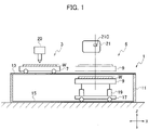
- the laser processing apparatus 1 (a general configuration thereof not illustrated) has shuttle tables 7 and 9 that are an example of a placement table and are reciprocable between a laser processing area (laser processing position) 3 and a standby area (standby position) 5. It is possible to employ one shuttle table (placement table), but a case of employing two tables will be explained.
- the laser processing apparatus having the shuttle tables reciprocable between the laser processing position 3 and the standby position 5 may have various configurations as mentioned in, for example, Japanese Patent Publication No. H5-65273 , Japanese Unexamined Patent Application Publication No. 2000-33444 , Japanese Patent Publication No. 3710871 , Japanese Patent Publication No. 4326252 , and the like. Accordingly, a detailed explanation for a general configuration of the laser processing apparatus 1 is omitted and an outline thereof will be explained.
- the laser processing apparatus 1 has a stand 11 of, for example, a box shape. On each side of a Y-axis direction (a direction orthogonal to a plane surface of Fig. 1 ) on the stand 11, a guide rail 13 is arranged to extend in an X-axis direction (left-right direction in Fig. 1 ).
- the guide rails 13 support the first shuttle table (placement table) 7 to reciprocate in the X-axis direction.
- guide rails 15 are arranged in the X-axis direction.
- the guide rails 15 support a movable cart 17.
- the movable cart 17 is provided with the vertically movable second shuttle table 9 (placement table) that is vertically moved by an up-down operation device 19 such as a fluid pressure cylinder.
- the second shuttle table 9 is movable in the X-axis direction to pass under the first shuttle table 7. And if lifted by the operation of the up-down operation device 19 at the laser processing position 3 or at the standby position 5, the second shuttle table 9 takes the same height as the first shuttle table 7. Namely, at the laser processing position 3 and standby position 5, the second shuttle table 9 is raised to take the same height as the first shuttle table 7.
- the first and second shuttle tables 7 and 9 are configured to synchronously move in opposite directions.
- a configuration to synchronously move the first and second shuttle tables 7 and 9 in opposite directions maybe similar to a conventional configuration. It is possible to separately drive the first and second shuttle tables 7 and 9 so that they are synchronously driven in opposite directions.
- the laser processing apparatus 1 is provided with a laser processing head 20 to perform laser processing on a plate-like work W on the first and second shuttle table 7and9 positioned at the laser processing position 3.
- the laser processing head 20 is arranged to be movable in the X-, Y-, and Z-axis directions with respect to the work W positioned at the laser processing position 3.
- a projector 21 is arranged as an example of a projecting device to project information concerning each cut piece placed on the first and second shuttle table 7 and 9 positioned at the standby position 5 onto the cut piece or onto a position adjacent to the cut piece. More precisely, on a side of the Y-axis direction of the stand 11, a movable cart (not shown) movable in the Y-axis direction is arranged to be positionally adjustable and fixable. And on a support post (not shown) uprightly arranged on the cart, the projector 21 is arranged so that it is positionally adjustable and fixable in an up-down direction. Namely, the projector 21 is arranged so that it can be positioned at a required position with respect to the stand 11 and can be fixed to the positioned position.
- the projector 21 is able to be arranged not only on a side of the Y-axis direction but also on a side of the X-axis direction. It is also possible to arrange the same at a position above the first and second shuttle table 7 and 9 positioned at the standby position 5.
- An X-axis-direction position of a lens of the projector 21 (hereafter referred to as an X-axis-direction center position 21C of the projector 21) is set at a position agreeing with an X-axis-direction center position of a maximum work W when the first and second shuttle table 7 and 9 on which the work W is placed is positioned at an origin position (reference position) of the standby position 5.
- the X-axis-direction center position of the first and second shuttle table 7 and 9 agrees with the X-axis-direction center position 21C of the projector 21.
- first and second shuttle tables 7 and 9 are alternately separately positioned at the origin position of the standby position 5.
- the second shuttle table 9 is lifted to the same height as the first shuttle table 7, the top face of the first and second shuttle table 7 and 9 alternately positioned to the standby position 5 and the projector 21 have a constant positional relationship in the X-axis direction.
- the projector 21 at the time of use is positionally adjusted in the Y- and X-axis directions and is kept in the position-adjusted state.
- aspect ratios vertical to horizontal ratios
- standard sizes of plate-like works are, for example, 4 x 8 (called: four by eight, size: 1219 mm x 2438 mm), 5 x 10 (called: five by ten, size: 1524 mm x 3048 mm), and the like.
- the X- and Y-direction maximum sizes are Xmax and Ymax.
- an X-axis-direction spread angle of the projector 21 is set as 2A.
- an X-axis-direction center position of the shuttle table 7 (9) alternately positioned to the standby position 5 agrees with an X-axis-direction center position of the projector 21.
- the spread angle 2A is adjusted such that both ends of the work W in the X-axis direction are contained in a projection range of the spread angle 2A.
- a height measurement from the top face of the shuttle table 7 (9) to the center position 21C of the projector 21 is set as d.
- a height position of the projector 21 is adjusted and set in advance so that an X-axis-direction projection range at the spread angle 2A becomes ⁇ Xmax' + Tmax x tan A ⁇ x 2 and a height dimension from the top face position of the shuttle table 7 (9) becomes d.
- supposing the plate thickness of a work processed by the laser processing apparatus is t
- an end part of the work of plate thickness t relative to the work W of plate thickness Tmax protrudes by a measurement Xr on each side of the X-axis direction as shown in Fig. 2
- the measurement Xr is a measurement of an area to be reduced when adjusting a projection range to the plate thickness Tmax.
- Y-axis-direction projection is conducted with the reduction ratio R.
- the height position of the projector 21 from the top face of the shuttle table 7 (9) is the measurement d.
- the maximum plate thickness of the work W placed on the shuttle table 7 (9) is Tmax and one end edge of the work W in the Y-axis direction is beforehand made coincide with a Y-axis-direction origin position (reference position).
- a Y-axis-direction spread angle of the projector 21 is B1 with respect to an upper end edge Yp above the origin position O of the work W having the plate thickness Tmax (namely, the edge Yp is an upper end edge of the maximum plate thickness Tmax at a vertically upper position above the Y-axis-direction origin position O spaced away from the projector 21).
- the edge Yp is an upper end edge of the maximum plate thickness Tmax at a vertically upper position above the Y-axis-direction origin position O spaced away from the projector 21.
- a projection position YA on the placement table 7 (9) spaced away from the projector 21 is reduced by the reduction ratio R and adjusted to the reference position O.
- Yr Tmax x tan B2.
- the aspect ratio of the projector 21 is 16:10 and the material ratio of the work W is 2:1.
- a processing range ratio of the work W is 2:1. Accordingly, it is impossible to adjust the processing range of the work as it is to the aspect ratio of the projector 21.
- an X-axis-direction part i.e., a horizontal direction of the aspect ratio 16:10 is assigned (allocated) to a longer direction of 2 of the material ratio 2:1 of the work W.
- a long side of the work W is assigned to a horizontal direction of the aspect ratio of the projector 21. Accordingly, a short side of the work W is assigned to a vertical direction of the aspect ratio.
- 1 of the material ratio 2:1 is assigned to 10 of the aspect ratio 16:10.
- Information concerning cut pieces to be projected onto the top face of the work W or onto a position adjacent to the work W is supplied from, for example, a personal computer to the projector.
- the information concerning cut pieces is, for example, coordinate position data relative to an origin position of the work W (layout position data on the work W) of the cut pieces (products) processed from the work W, shape data of the respective cut pieces, and the like.
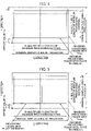
- Figures 4 and 5 show images prepared according to results of the above-mentioned calculations.
- Figure 4 shows a configuration of a relative relationship between a material and a projector position that is adjusted to be able to conduct projection over a maximum processing range in the X-axis direction with a processing maximum range and maximum stack height.
- the reduction ratio is 1 and the reduction ratio of a formed image is determined according to a stack height.
- a projection image is beforehand reduced because a projected image enlarges as a material becomes distal (a stack height becomes lower).
- a projection point of the projector and the center of a maximum processing material are arranged to agree with each other, and therefore, a place on the X-axis is determined with that reduction ratio.
- a Y position is spaced away from the reference position by Yo depending on the stack height (refer to Fig. 3 ).
- Figure 5 is a view showing an image of a small material together with an estimated image of the reference maximum processing work.
- a display position is corrected by Yo that is a shift from a material-positioned reference point and varies depending on a stack height (plate thickness in the case of one piece).
- the information projecting apparatus is provided with the projector 21 and the placement tables (shuttle tables 7 and 9) in order to project information concerning cut pieces (products) onto top faces of the cut pieces that are placed on the shuttle table 7 and 9, i. e. , the placement table positioned at the predetermined position (standby area 5) or onto a position adjacent to the cut pieces.
- the predetermined position is a position where the cut pieces on the placement table are sorted and carried to the next process.
- the placement table is positioned at the predetermined position in a state that a plurality of cut pieces are placed on the top face thereof.
- the cut pieces are placed on the placement table as in a state that they are cut by, for example, the laser processing apparatus.
- the cut pieces may beforehand be selected according to their sizes, shapes, and the like and may beforehand regularly be stacked and arranged at predetermined positions on the placement table. In this case, top face heights of the stacked cut pieces are always kept substantially at a fixed level. Accordingly, even if the information concerning the cut pieces is projected on the top faces of the respective cut pieces on the placement table, the cut pieces are not shaded.
- the projector 21 projects information concerning cut pieces onto the top face of a work W (cut pieces) on the shuttle table 7 (9) moved from the laser processing position 3 to the standby position 5 and positioned thereat or onto a position adjacent to the cut pieces so that the cut pieces are sorted and carried.
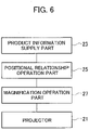
- the projector 21 is connected to, as shown in Fig. 6 , a product information supply part 23 to supply product information to the projector 21.
- the product information supply part 23 is, for example, a personal computer that stores product information, an automatic programming device that supplies nesting data such as the arranged positions, shapes, measurements, and plate thicknesses of cut pieces arranged on a work W, or an NC device of the laser processing apparatus 1.
- the product information supply part 23 includes a projector setting information supply part such as a personal computer to supply data for the setting height d and data for the spread angles 2A, B1, and B2 of the projector 21.
- the product information supply part 23 may employ, when cut pieces are stacked on the placement table, a configuration to manually input the plate thicknesses, arranged positions, shapes, and measurement data of the respective cut pieces.
- the projector 21 is connected to a positional relationship operation part 25 to operate the positional relationship d between a cut piece and the projector 21 according to plate thickness information t of a work W on the placement table (shuttle table 7 and 9) positioned at the predetermined position (standby position 5).
- Tmax is a stack height measurement when a plurality of cut pieces are stacked.
- the projector 21 is connected to a magnification operation part 27 to operate a zoom ratio of the projector 21 according to the height position data d operated by the positional relationship operation part 25.
- the magnification of the projector 21 is changed to project information concerning a cut piece onto the cut piece or onto a position adjacent to the cut piece.
- a worker sees information concerning cut pieces projected onto the cut pieces of a work W on the shuttle table 7 (9) at the standby position 5 and sorts the cut pieces for the next process.
- the cut piece sorting work by the worker can easily be achieved.
- the projector 21 displays and specifies a cut piece to be carried from among cut pieces on the shuttle table 7 (9), it is possible to project a different color onto the cut piece to be carried instead of the configuration of projecting information concerning the cut piece onto the top face of the cut piece or onto an adjacent position. It is also possible to conduct blinking projection onto the cut piece to be carried. Further, it is possible to display and specify the cut piece to be carried by projecting (emitting) a light spot onto the top face of the cut piece to be carried.
- the configuration to display and specify a cut piece that is on the shuttle table 7 (9) and is to be carried is also realizable by properly combining a plurality of the above-mentioned displaying and specifying techniques.
- the top face of the shuttle table 7 (9) serving as a placement table at the standby position 5 is used as a reference and the zoom ratio R is operated according to a plate thickness (work stacking height) on the shuttle table 7 (9).
- the operated magnification (zoom ratio) and a Y-direction image shift conforming to the magnification information concerning the cut piece is projected onto the top face of the cut piece or onto a position adjacent to the cut piece.
- the present invention is not limited to the above-mentioned embodiments, and by achieving proper modifications , the present invention can be embodied in other forms. Namely, the present invention is also applicable to a case that beforehand places a plural kinds of processed items at the same height on a pallet, i.e., a placement table, sorts the processed items on the pallet for, for example, delivery time, and carries them out.
- a placement table sorts the processed items on the pallet for, for example, delivery time, and carries them out.
- a positional relationship between a projector and a top face of a work on a placement table such as a pallet is found according to plate thickness information of the work, and with a zoom ratio based on the found positional relationship, information concerning a cut piece is projected onto a top face of the cut piece or onto a position adjacent to the cut piece. Accordingly, it is possible to always maintain the projector at a fixed position and correctly project the information with respect to the cut piece.
Landscapes
- Engineering & Computer Science (AREA)
- Physics & Mathematics (AREA)
- Optics & Photonics (AREA)
- Mechanical Engineering (AREA)
- Plasma & Fusion (AREA)
- Multimedia (AREA)
- Signal Processing (AREA)
- Geometry (AREA)
- Laser Beam Processing (AREA)
Claims (6)
- Informationsprojektionsverfahren zum Projizieren von ein geschnittenes Teil betreffende Informationen auf das geschnittene Teil, wobei das geschnittene Teil geschnitten und von einem plattenartigen Werkstück (W) getrennt ist und wobei sich das geschnittene Teil auf einem Platzierungstisch (7, 9) befindet, wobei das Informationsprojektionsverfahren folgendes umfasst:Einstellen eines Seitenverhältnisses eines Projektors (21) auf ein Materialverhältnis einer langen Seite des Werkstücks (W) zu einer kurzen Seite des Werkstücks (W) durch:Zuordnen der langen Seite des Werkstücks (W) zu einer horizontalen Ausdehnung des Seitenverhältnisses des Projektors (21), die in Richtung einer X-Achse ausgerichtet ist; undZuordnen der kurzen Seite des Werkstücks (W) zu einer vertikalen Ausdehnung des Seitenverhältnisses des Projektors (21), die in Richtung der Y-Achse ausgerichtet ist;positionsmäßiges Einstellen des Projektors (21) und Halten des Projektors (21) in dem eingestellten Zustand, wobei eine Positionsbeziehung zwischen dem Projektor (21) und einer vorbestimmten Position des Platzierungstisches (7, 9) in der X-Achsen-Richtung, eine Positionsbeziehung zwischen dem Projektor (21) und der vorbestimmten Position des Platzierungstisches (7, 9) in der Y-Achsen-Richtung und eine Positionsbeziehung zwischen einer oberen Fläche des Platzierungstisches (7, 9) und dem Projektor (21) in einer Z-Achsen-Richtung festgelegt sind;Finden einer Positionsbeziehung zwischen einer Oberseite des Werkstücks (W) und dem Projektor (21) gemäß einer Plattendicke des Werkstücks (W) und/oder einer Anzahl von gestapelten geschnittenen Teilen auf dem Platzierungstisch (7, 9), wobei der Platzierungstisch (7, 9) an der vorbestimmten Position positioniert ist;Ermitteln eines Vergrößerungsfaktors entsprechend der gefundenen Positionsbeziehung;Ermitteln einer Bildverschiebung in Y-Richtung entsprechend dem Vergrößerungsfaktor; undProjizieren der Information über das geschnittene Teil auf das geschnittene Teil mit dem Vergrößerungsfaktor und der Bildverschiebung in Y-Richtung.
- Informationsprojektionsverfahren nach Anspruch 1, wobei,wenn ein X-Achsen-Richtungs-Vergrößerungsfaktor des Werkstücks (W) mit einem Y-Achsen-Richtungs-Vergrößerungsfaktor des Werkstücks (W) ausgeglichen ist und ein Spreizwinkel B1 als ein Y-Achsen-Spreizwinkel des Projektors (21) zum Zeitpunkt der Durchführung der Projektion auf eine obere Endkante eines Bearbeitungsobjekts, das eine maximale Plattendicke (Tmax) aufweist, an einer Y-Achsen-Richtungs-Ursprungsposition (O) entfernt von dem Projektor (21) eingestellt wird,eine Projektionsposition, die sich zum Zeitpunkt der Durchführung der Projektion mit dem Spreizwinkel B1 auf eine Plattendicke von Null auf dem Platzierungstisch (7, 9) befindet und von dem Projektor (21) entfernt ist, auf eine Referenzposition des Werkstücks eingestellt wird.
- Informationsprojektionsverfahren nach Anspruch 1 oder 2, wobei eine Projektion mit verschiedenen Farben auf ein zu tragendes geschnittenes Teil durchgeführt wird, eine blinkende Projektion auf das zu tragende geschnittene Teil durchgeführt wird oder ein Lichtpunkt auf eine Oberseite der zu tragenden geschnittenen Teile projiziert wird, wodurch das zu tragende geschnittene Teil angezeigt und spezifiziert wird.
- Informationsprojektionsvorrichtung zum Projizieren von ein geschnittenes Teil betreffende Informationen auf das geschnittene Teil, wobei das geschnittene Teil geschnitten und von einem plattenartigen Werkstück (W) getrennt ist, wobei die Informationsprojektionsvorrichtung folgendes umfasst:einen Platzierungstisch (7, 9), auf dem das geschnittene Teil platziert wird;einen Projektor (21), der die Informationen bezüglich des geschnittenen Teils auf eine Oberseite des geschnittenen Teils auf den Platzierungstisch (7, 9) projiziert, wenn der Platzierungstisch (7, 9) an einer vorbestimmten Position positioniert ist;Mittel zum Anpassen eines Seitenverhältnisses eines Projektors (21) an ein Materialverhältnis einer langen Seite des Werkstücks (W) zu einer kurzen Seite des Werkstücks (W) durch:Zuordnen der langen Seite des Werkstücks (W) zu einer horizontalen Ausdehnung des Seitenverhältnisses des Projektors (21), die in einer X-Achsenrichtung ausgerichtet ist; undZuordnen der kurzen Seite des Werkstücks (W) zu einer vertikalen Ausdehnung des Seitenverhältnisses des Projektors (21), die in Richtung der Y-Achse ausgerichtet ist;Mittel zur Positionseinstellung des Projektors (21) und zum Halten des Projektors (21) in dem eingestellten Zustand, wobei eine Positionsbeziehung zwischen dem Projektor (21) und der vorbestimmten Position des Platzierungstisches (7, 9) in der X-Achsen-Richtung, eine Positionsbeziehung zwischen dem Projektor (21) und der vorbestimmten Position des Platzierungstisches (7, 9) in der Y-Achsen-Richtung und eine Höhenposition (d) von der oberen Fläche des Platzierungstisches (7, 9) zu dem Projektor (21) festgelegt sind;Mittel zum Finden einer Positionsbeziehung zwischen der Oberseite des Werkstücks (W) und dem Projektor gemäß einer Plattendicke des Werkstücks (W) auf dem Platzierungstisch und/oder einer Anzahl von gestapelten geschnittenen Teilen auf dem Platzierungstisch;Mittel zum Erhalten eines Vergrößerungsfaktors des Projektors (21) gemäß der gefundenen Positionsbeziehung; undMittel zum Erhalten einer Bildverschiebung in Y-Richtung entsprechend dem Vergrößerungsfaktor;wobei der Projektor (21) so konfiguriert ist, dass er die Informationen, die das geschnittene Stück betreffen, auf das geschnittene Teil mit dem Vergrößerungsfaktor und der Bildverschiebung in Y-Richtung projiziert.
- Informationsprojektionsvorrichtung nach Anspruch 4, die einen Positionsbeziehungs-Betriebsteil (25) umfasst, der so konfiguriert ist, dass er die Positionsbeziehung gemäß einer Koordinatenposition des Projektors (21), der an einer vorbestimmten Position in Y-Achsen-Richtung angeordnet ist, und einer Plattendicke (t) des geschnittenen Teils, einer Plattendicke eines Werkstücks (W) oder einer gestapelten Anzahl auf dem Platzierungstisch (7, 9) betreibt.
- Laserbearbeitungsvorrichtung (1) mit einem Pendeltisch, der zwischen einer Laserbearbeitungsposition (3) und einer Bereitschaftsposition (5) hin- und herbewegt werden kann, mit der Informationsprojektionsvorrichtung nach Anspruch 4 oder 5 an einer Seitenposition in Y-Achsen-Richtung in der Bereitschaftsposition.
Applications Claiming Priority (2)
| Application Number | Priority Date | Filing Date | Title |
|---|---|---|---|
| JP2017152150A JP6524156B2 (ja) | 2017-08-07 | 2017-08-07 | 情報投影方法及び装置並びにレーザ加工装置 |
| PCT/JP2018/027603 WO2019031222A1 (ja) | 2017-08-07 | 2018-07-24 | 情報投影方法及び装置並びにレーザ加工装置 |
Publications (3)
| Publication Number | Publication Date |
|---|---|
| EP3666450A1 EP3666450A1 (de) | 2020-06-17 |
| EP3666450A4 EP3666450A4 (de) | 2021-05-19 |
| EP3666450B1 true EP3666450B1 (de) | 2022-10-26 |
Family
ID=65271359
Family Applications (1)
| Application Number | Title | Priority Date | Filing Date |
|---|---|---|---|
| EP18842905.4A Active EP3666450B1 (de) | 2017-08-07 | 2018-07-24 | Informationsprojektionsverfahren und -vorrichtung und laserbearbeitungsvorrichtung |
Country Status (5)
| Country | Link |
|---|---|
| US (1) | US10974347B2 (de) |
| EP (1) | EP3666450B1 (de) |
| JP (1) | JP6524156B2 (de) |
| CN (1) | CN110997222B (de) |
| WO (1) | WO2019031222A1 (de) |
Families Citing this family (4)
| Publication number | Priority date | Publication date | Assignee | Title |
|---|---|---|---|---|
| CN110693618B (zh) * | 2019-10-15 | 2021-11-16 | 浙江隐齿丽医学技术有限公司 | 确定壳状牙齿矫治器切割方向的方法、装置及电子设备 |
| JP2022098586A (ja) * | 2020-12-22 | 2022-07-04 | 大船企業日本株式会社 | プリント基板レーザ加工装置に装着されるアパーチャにおける加工点パワーの調整方法と、該プリント基板レーザ加工装置に装着されるアパーチャにおける加工点パワーの調整方法を実施してなるプリント基板レーザ加工装置 |
| JP7556807B2 (ja) | 2021-03-04 | 2024-09-26 | トヨタ自動車株式会社 | 位置決め支援装置 |
| CN113505407A (zh) * | 2021-06-22 | 2021-10-15 | 筑友智造建设科技集团有限公司 | 基于投影的预制构件生产方法、系统、设备及存储介质 |
Family Cites Families (21)
| Publication number | Priority date | Publication date | Assignee | Title |
|---|---|---|---|---|
| JPS6316895A (ja) * | 1986-07-07 | 1988-01-23 | Yamazaki Mazak Corp | レ−ザ加工機 |
| JPH0565273A (ja) | 1989-04-27 | 1993-03-19 | Otsuka Pharmaceut Co Ltd | カルボスチリル誘導体 |
| DE4140428A1 (de) * | 1991-12-07 | 1993-06-09 | Hans Berger Messtechnik Gmbh, 5600 Wuppertal, De | Hilfseinrichtung zum positionieren von werkstuecken und presse oder stanze |
| US5304773A (en) * | 1992-02-19 | 1994-04-19 | Trumpf Inc. | Laser work station with optical sensor for calibration of guidance system |
| JP3602199B2 (ja) * | 1994-06-15 | 2004-12-15 | 株式会社アマダ | 材料寸法測定装置 |
| JP3223416B2 (ja) * | 1995-12-05 | 2001-10-29 | 株式会社日立製作所 | 加工位置検出装置および自動加工システム |
| JP3710871B2 (ja) | 1996-03-11 | 2005-10-26 | 株式会社アマダ | 熱切断加工機用テーブル装置 |
| JP4162062B2 (ja) | 1998-07-22 | 2008-10-08 | 株式会社アマダ | シャトルテーブル装置 |
| JP2002169604A (ja) * | 2000-12-04 | 2002-06-14 | Hitachi Ltd | 作業指示システム |
| JP2002196736A (ja) * | 2000-12-26 | 2002-07-12 | Seiko Epson Corp | アスペクト比に応じたプロジェクタの投写サイズ調整 |
| JP2004046730A (ja) * | 2002-07-15 | 2004-02-12 | Kawasaki Heavy Ind Ltd | 作業指示方法および作業指示システム |
| JP4326252B2 (ja) | 2003-04-08 | 2009-09-02 | 株式会社アマダ | シャトル式ワークテーブル装置及びシャトル式ワークテーブル交換方法 |
| EP1524063A1 (de) * | 2003-10-08 | 2005-04-20 | Trumpf Werkzeugmaschinen GmbH + Co. KG | Markierungsvorrichtung und Ablaufsteuerverfahren für geschnittene oder gestanzte Werkstücke einer Platte |
| JP2007208905A (ja) | 2006-02-06 | 2007-08-16 | Olympus Corp | 情報呈示装置 |
| JP5484029B2 (ja) * | 2009-12-18 | 2014-05-07 | 株式会社島精機製作所 | 裁断装置 |
| CN202339469U (zh) * | 2011-10-31 | 2012-07-18 | 上海显恒光电科技股份有限公司 | 采用环形电子束激发激光光源的投影系统 |
| JP5866240B2 (ja) * | 2012-03-29 | 2016-02-17 | 株式会社アマダホールディングス | 棚装置及び棚装置に使用する投影装置 |
| US9644942B2 (en) * | 2012-11-29 | 2017-05-09 | Mitsubishi Hitachi Power Systems, Ltd. | Method and apparatus for laser projection, and machining method |
| CN203807484U (zh) * | 2014-04-27 | 2014-09-03 | 武汉斯雷博科技有限公司 | 一种全幅投影真皮激光切割机 |
| JP2017076943A (ja) * | 2015-10-16 | 2017-04-20 | 富士通株式会社 | コンテンツ投影装置、コンテンツ投影方法及びコンテンツ投影プログラム |
| CN105483296A (zh) * | 2015-12-24 | 2016-04-13 | 上海和鹰机电科技股份有限公司 | 数控裁剪机 |
-
2017
- 2017-08-07 JP JP2017152150A patent/JP6524156B2/ja active Active
-
2018
- 2018-07-24 WO PCT/JP2018/027603 patent/WO2019031222A1/ja not_active Ceased
- 2018-07-24 US US16/635,785 patent/US10974347B2/en active Active
- 2018-07-24 CN CN201880051188.9A patent/CN110997222B/zh active Active
- 2018-07-24 EP EP18842905.4A patent/EP3666450B1/de active Active
Also Published As
| Publication number | Publication date |
|---|---|
| JP2019030885A (ja) | 2019-02-28 |
| EP3666450A1 (de) | 2020-06-17 |
| EP3666450A4 (de) | 2021-05-19 |
| JP6524156B2 (ja) | 2019-06-05 |
| US10974347B2 (en) | 2021-04-13 |
| WO2019031222A1 (ja) | 2019-02-14 |
| CN110997222A (zh) | 2020-04-10 |
| CN110997222B (zh) | 2020-12-15 |
| US20200376604A1 (en) | 2020-12-03 |
Similar Documents
| Publication | Publication Date | Title |
|---|---|---|
| EP3666450B1 (de) | Informationsprojektionsverfahren und -vorrichtung und laserbearbeitungsvorrichtung | |
| TWI510317B (zh) | 雷射加工方法及雷射加工裝置 | |
| US20170115656A1 (en) | Image-Based Placing of Workpiece Machining Operations | |
| US9483040B2 (en) | Program and device which automatically generate operation program | |
| US20100193479A1 (en) | Laser processing apparatus, process control apparatus, and processing apparatus | |
| JP5866240B2 (ja) | 棚装置及び棚装置に使用する投影装置 | |
| JPWO2005107354A1 (ja) | プリント基板支持装置 | |
| WO2014119304A1 (ja) | 下受けピンの配置決定支援装置および配置決定支援方法 | |
| IT201600105846A1 (it) | METODO E SISTEMA PER Il TAGLIO AUTOMATICO DI TESSUTO | |
| JP2022168306A (ja) | 対基板作業機および対基板作業機システム | |
| US20160114595A1 (en) | Multiple part decoration system and method | |
| WO2021044620A1 (ja) | 部品実装機のバックアップピン自動配置システム | |
| JP5903588B2 (ja) | 下受けピンの配置決定支援装置および配置決定支援方法 | |
| JP5301919B2 (ja) | 硬質脆性板の面取装置 | |
| CN112119681B (zh) | 支承构件配置决定装置、支承构件配置决定方法 | |
| CN106637886A (zh) | 一种具有智能定位功能的服装点位机 | |
| WO2021234848A1 (ja) | 部品実装システム | |
| US12226795B2 (en) | Dispense volume adjustment based on gap width of located features | |
| JP4185367B2 (ja) | 支持部材配置作業支援装置,それを備える対基板作業システムおよび支持部材配置方法 | |
| JP7487075B2 (ja) | 干渉確認装置及びそれを備えた処理機 | |
| JPWO2019053897A1 (ja) | 実装システム | |
| JPH11351854A (ja) | 検査体位置決め装置および検査体位置決め方法 | |
| JP2026510745A (ja) | 交差コマンドビジョン位置特定システム及び方法 | |
| EP3823427B1 (de) | Bildverarbeitungsverfahren und bestückungsmaschine | |
| JP2000249662A (ja) | テープキャリア欠陥検査装置及びテープキャリア欠陥検査装置における撮像手段の位置合わせ方法 |
Legal Events
| Date | Code | Title | Description |
|---|---|---|---|
| STAA | Information on the status of an ep patent application or granted ep patent |
Free format text: STATUS: THE INTERNATIONAL PUBLICATION HAS BEEN MADE |
|
| PUAI | Public reference made under article 153(3) epc to a published international application that has entered the european phase |
Free format text: ORIGINAL CODE: 0009012 |
|
| STAA | Information on the status of an ep patent application or granted ep patent |
Free format text: STATUS: REQUEST FOR EXAMINATION WAS MADE |
|
| 17P | Request for examination filed |
Effective date: 20200303 |
|
| AK | Designated contracting states |
Kind code of ref document: A1 Designated state(s): AL AT BE BG CH CY CZ DE DK EE ES FI FR GB GR HR HU IE IS IT LI LT LU LV MC MK MT NL NO PL PT RO RS SE SI SK SM TR |
|
| AX | Request for extension of the european patent |
Extension state: BA ME |
|
| DAV | Request for validation of the european patent (deleted) | ||
| DAX | Request for extension of the european patent (deleted) | ||
| A4 | Supplementary search report drawn up and despatched |
Effective date: 20210419 |
|
| RIC1 | Information provided on ipc code assigned before grant |
Ipc: B23K 26/70 20140101AFI20210413BHEP Ipc: B23K 26/38 20140101ALI20210413BHEP Ipc: G01B 11/25 20060101ALI20210413BHEP Ipc: B23K 37/00 20060101ALI20210413BHEP Ipc: B26D 7/27 20060101ALI20210413BHEP Ipc: H04N 9/31 20060101ALI20210413BHEP |
|
| STAA | Information on the status of an ep patent application or granted ep patent |
Free format text: STATUS: EXAMINATION IS IN PROGRESS |
|
| 17Q | First examination report despatched |
Effective date: 20211129 |
|
| GRAP | Despatch of communication of intention to grant a patent |
Free format text: ORIGINAL CODE: EPIDOSNIGR1 |
|
| STAA | Information on the status of an ep patent application or granted ep patent |
Free format text: STATUS: GRANT OF PATENT IS INTENDED |
|
| INTG | Intention to grant announced |
Effective date: 20220707 |
|
| GRAS | Grant fee paid |
Free format text: ORIGINAL CODE: EPIDOSNIGR3 |
|
| GRAA | (expected) grant |
Free format text: ORIGINAL CODE: 0009210 |
|
| STAA | Information on the status of an ep patent application or granted ep patent |
Free format text: STATUS: THE PATENT HAS BEEN GRANTED |
|
| AK | Designated contracting states |
Kind code of ref document: B1 Designated state(s): AL AT BE BG CH CY CZ DE DK EE ES FI FR GB GR HR HU IE IS IT LI LT LU LV MC MK MT NL NO PL PT RO RS SE SI SK SM TR |
|
| REG | Reference to a national code |
Ref country code: GB Ref legal event code: FG4D |
|
| REG | Reference to a national code |
Ref country code: CH Ref legal event code: EP |
|
| REG | Reference to a national code |
Ref country code: AT Ref legal event code: REF Ref document number: 1526708 Country of ref document: AT Kind code of ref document: T Effective date: 20221115 |
|
| REG | Reference to a national code |
Ref country code: DE Ref legal event code: R096 Ref document number: 602018042367 Country of ref document: DE |
|
| REG | Reference to a national code |
Ref country code: IE Ref legal event code: FG4D |
|
| REG | Reference to a national code |
Ref country code: LT Ref legal event code: MG9D |
|
| REG | Reference to a national code |
Ref country code: NL Ref legal event code: MP Effective date: 20221026 |
|
| REG | Reference to a national code |
Ref country code: AT Ref legal event code: MK05 Ref document number: 1526708 Country of ref document: AT Kind code of ref document: T Effective date: 20221026 |
|
| PG25 | Lapsed in a contracting state [announced via postgrant information from national office to epo] |
Ref country code: NL Free format text: LAPSE BECAUSE OF FAILURE TO SUBMIT A TRANSLATION OF THE DESCRIPTION OR TO PAY THE FEE WITHIN THE PRESCRIBED TIME-LIMIT Effective date: 20221026 |
|
| PG25 | Lapsed in a contracting state [announced via postgrant information from national office to epo] |
Ref country code: SE Free format text: LAPSE BECAUSE OF FAILURE TO SUBMIT A TRANSLATION OF THE DESCRIPTION OR TO PAY THE FEE WITHIN THE PRESCRIBED TIME-LIMIT Effective date: 20221026 Ref country code: PT Free format text: LAPSE BECAUSE OF FAILURE TO SUBMIT A TRANSLATION OF THE DESCRIPTION OR TO PAY THE FEE WITHIN THE PRESCRIBED TIME-LIMIT Effective date: 20230227 Ref country code: NO Free format text: LAPSE BECAUSE OF FAILURE TO SUBMIT A TRANSLATION OF THE DESCRIPTION OR TO PAY THE FEE WITHIN THE PRESCRIBED TIME-LIMIT Effective date: 20230126 Ref country code: LT Free format text: LAPSE BECAUSE OF FAILURE TO SUBMIT A TRANSLATION OF THE DESCRIPTION OR TO PAY THE FEE WITHIN THE PRESCRIBED TIME-LIMIT Effective date: 20221026 Ref country code: FI Free format text: LAPSE BECAUSE OF FAILURE TO SUBMIT A TRANSLATION OF THE DESCRIPTION OR TO PAY THE FEE WITHIN THE PRESCRIBED TIME-LIMIT Effective date: 20221026 Ref country code: ES Free format text: LAPSE BECAUSE OF FAILURE TO SUBMIT A TRANSLATION OF THE DESCRIPTION OR TO PAY THE FEE WITHIN THE PRESCRIBED TIME-LIMIT Effective date: 20221026 Ref country code: AT Free format text: LAPSE BECAUSE OF FAILURE TO SUBMIT A TRANSLATION OF THE DESCRIPTION OR TO PAY THE FEE WITHIN THE PRESCRIBED TIME-LIMIT Effective date: 20221026 |
|
| PG25 | Lapsed in a contracting state [announced via postgrant information from national office to epo] |
Ref country code: RS Free format text: LAPSE BECAUSE OF FAILURE TO SUBMIT A TRANSLATION OF THE DESCRIPTION OR TO PAY THE FEE WITHIN THE PRESCRIBED TIME-LIMIT Effective date: 20221026 Ref country code: PL Free format text: LAPSE BECAUSE OF FAILURE TO SUBMIT A TRANSLATION OF THE DESCRIPTION OR TO PAY THE FEE WITHIN THE PRESCRIBED TIME-LIMIT Effective date: 20221026 Ref country code: LV Free format text: LAPSE BECAUSE OF FAILURE TO SUBMIT A TRANSLATION OF THE DESCRIPTION OR TO PAY THE FEE WITHIN THE PRESCRIBED TIME-LIMIT Effective date: 20221026 Ref country code: IS Free format text: LAPSE BECAUSE OF FAILURE TO SUBMIT A TRANSLATION OF THE DESCRIPTION OR TO PAY THE FEE WITHIN THE PRESCRIBED TIME-LIMIT Effective date: 20230226 Ref country code: HR Free format text: LAPSE BECAUSE OF FAILURE TO SUBMIT A TRANSLATION OF THE DESCRIPTION OR TO PAY THE FEE WITHIN THE PRESCRIBED TIME-LIMIT Effective date: 20221026 Ref country code: GR Free format text: LAPSE BECAUSE OF FAILURE TO SUBMIT A TRANSLATION OF THE DESCRIPTION OR TO PAY THE FEE WITHIN THE PRESCRIBED TIME-LIMIT Effective date: 20230127 |
|
| P01 | Opt-out of the competence of the unified patent court (upc) registered |
Effective date: 20230428 |
|
| REG | Reference to a national code |
Ref country code: DE Ref legal event code: R097 Ref document number: 602018042367 Country of ref document: DE |
|
| PG25 | Lapsed in a contracting state [announced via postgrant information from national office to epo] |
Ref country code: SM Free format text: LAPSE BECAUSE OF FAILURE TO SUBMIT A TRANSLATION OF THE DESCRIPTION OR TO PAY THE FEE WITHIN THE PRESCRIBED TIME-LIMIT Effective date: 20221026 Ref country code: RO Free format text: LAPSE BECAUSE OF FAILURE TO SUBMIT A TRANSLATION OF THE DESCRIPTION OR TO PAY THE FEE WITHIN THE PRESCRIBED TIME-LIMIT Effective date: 20221026 Ref country code: EE Free format text: LAPSE BECAUSE OF FAILURE TO SUBMIT A TRANSLATION OF THE DESCRIPTION OR TO PAY THE FEE WITHIN THE PRESCRIBED TIME-LIMIT Effective date: 20221026 Ref country code: DK Free format text: LAPSE BECAUSE OF FAILURE TO SUBMIT A TRANSLATION OF THE DESCRIPTION OR TO PAY THE FEE WITHIN THE PRESCRIBED TIME-LIMIT Effective date: 20221026 Ref country code: CZ Free format text: LAPSE BECAUSE OF FAILURE TO SUBMIT A TRANSLATION OF THE DESCRIPTION OR TO PAY THE FEE WITHIN THE PRESCRIBED TIME-LIMIT Effective date: 20221026 |
|
| PG25 | Lapsed in a contracting state [announced via postgrant information from national office to epo] |
Ref country code: SK Free format text: LAPSE BECAUSE OF FAILURE TO SUBMIT A TRANSLATION OF THE DESCRIPTION OR TO PAY THE FEE WITHIN THE PRESCRIBED TIME-LIMIT Effective date: 20221026 Ref country code: AL Free format text: LAPSE BECAUSE OF FAILURE TO SUBMIT A TRANSLATION OF THE DESCRIPTION OR TO PAY THE FEE WITHIN THE PRESCRIBED TIME-LIMIT Effective date: 20221026 |
|
| PLBE | No opposition filed within time limit |
Free format text: ORIGINAL CODE: 0009261 |
|
| STAA | Information on the status of an ep patent application or granted ep patent |
Free format text: STATUS: NO OPPOSITION FILED WITHIN TIME LIMIT |
|
| 26N | No opposition filed |
Effective date: 20230727 |
|
| PG25 | Lapsed in a contracting state [announced via postgrant information from national office to epo] |
Ref country code: SI Free format text: LAPSE BECAUSE OF FAILURE TO SUBMIT A TRANSLATION OF THE DESCRIPTION OR TO PAY THE FEE WITHIN THE PRESCRIBED TIME-LIMIT Effective date: 20221026 |
|
| PG25 | Lapsed in a contracting state [announced via postgrant information from national office to epo] |
Ref country code: MC Free format text: LAPSE BECAUSE OF FAILURE TO SUBMIT A TRANSLATION OF THE DESCRIPTION OR TO PAY THE FEE WITHIN THE PRESCRIBED TIME-LIMIT Effective date: 20221026 |
|
| PG25 | Lapsed in a contracting state [announced via postgrant information from national office to epo] |
Ref country code: MC Free format text: LAPSE BECAUSE OF FAILURE TO SUBMIT A TRANSLATION OF THE DESCRIPTION OR TO PAY THE FEE WITHIN THE PRESCRIBED TIME-LIMIT Effective date: 20221026 |
|
| REG | Reference to a national code |
Ref country code: CH Ref legal event code: PL |
|
| REG | Reference to a national code |
Ref country code: BE Ref legal event code: MM Effective date: 20230731 |
|
| PG25 | Lapsed in a contracting state [announced via postgrant information from national office to epo] |
Ref country code: LU Free format text: LAPSE BECAUSE OF NON-PAYMENT OF DUE FEES Effective date: 20230724 |
|
| PG25 | Lapsed in a contracting state [announced via postgrant information from national office to epo] |
Ref country code: LU Free format text: LAPSE BECAUSE OF NON-PAYMENT OF DUE FEES Effective date: 20230724 |
|
| REG | Reference to a national code |
Ref country code: IE Ref legal event code: MM4A |
|
| PG25 | Lapsed in a contracting state [announced via postgrant information from national office to epo] |
Ref country code: CH Free format text: LAPSE BECAUSE OF NON-PAYMENT OF DUE FEES Effective date: 20230731 |
|
| PG25 | Lapsed in a contracting state [announced via postgrant information from national office to epo] |
Ref country code: IT Free format text: LAPSE BECAUSE OF FAILURE TO SUBMIT A TRANSLATION OF THE DESCRIPTION OR TO PAY THE FEE WITHIN THE PRESCRIBED TIME-LIMIT Effective date: 20221026 Ref country code: BE Free format text: LAPSE BECAUSE OF NON-PAYMENT OF DUE FEES Effective date: 20230731 |
|
| PG25 | Lapsed in a contracting state [announced via postgrant information from national office to epo] |
Ref country code: IE Free format text: LAPSE BECAUSE OF NON-PAYMENT OF DUE FEES Effective date: 20230724 |
|
| PG25 | Lapsed in a contracting state [announced via postgrant information from national office to epo] |
Ref country code: IE Free format text: LAPSE BECAUSE OF NON-PAYMENT OF DUE FEES Effective date: 20230724 |
|
| PG25 | Lapsed in a contracting state [announced via postgrant information from national office to epo] |
Ref country code: BG Free format text: LAPSE BECAUSE OF FAILURE TO SUBMIT A TRANSLATION OF THE DESCRIPTION OR TO PAY THE FEE WITHIN THE PRESCRIBED TIME-LIMIT Effective date: 20221026 |
|
| PG25 | Lapsed in a contracting state [announced via postgrant information from national office to epo] |
Ref country code: BG Free format text: LAPSE BECAUSE OF FAILURE TO SUBMIT A TRANSLATION OF THE DESCRIPTION OR TO PAY THE FEE WITHIN THE PRESCRIBED TIME-LIMIT Effective date: 20221026 |
|
| PG25 | Lapsed in a contracting state [announced via postgrant information from national office to epo] |
Ref country code: CY Free format text: LAPSE BECAUSE OF FAILURE TO SUBMIT A TRANSLATION OF THE DESCRIPTION OR TO PAY THE FEE WITHIN THE PRESCRIBED TIME-LIMIT; INVALID AB INITIO Effective date: 20180724 |
|
| PG25 | Lapsed in a contracting state [announced via postgrant information from national office to epo] |
Ref country code: HU Free format text: LAPSE BECAUSE OF FAILURE TO SUBMIT A TRANSLATION OF THE DESCRIPTION OR TO PAY THE FEE WITHIN THE PRESCRIBED TIME-LIMIT; INVALID AB INITIO Effective date: 20180724 |
|
| PGFP | Annual fee paid to national office [announced via postgrant information from national office to epo] |
Ref country code: DE Payment date: 20250722 Year of fee payment: 8 |
|
| PGFP | Annual fee paid to national office [announced via postgrant information from national office to epo] |
Ref country code: GB Payment date: 20250722 Year of fee payment: 8 |
|
| PGFP | Annual fee paid to national office [announced via postgrant information from national office to epo] |
Ref country code: FR Payment date: 20250725 Year of fee payment: 8 |
|
| PG25 | Lapsed in a contracting state [announced via postgrant information from national office to epo] |
Ref country code: TR Free format text: LAPSE BECAUSE OF FAILURE TO SUBMIT A TRANSLATION OF THE DESCRIPTION OR TO PAY THE FEE WITHIN THE PRESCRIBED TIME-LIMIT Effective date: 20221026 |