EP3660818B1 - Anzeigevorrichtung - Google Patents
Anzeigevorrichtung Download PDFInfo
- Publication number
- EP3660818B1 EP3660818B1 EP19211836.2A EP19211836A EP3660818B1 EP 3660818 B1 EP3660818 B1 EP 3660818B1 EP 19211836 A EP19211836 A EP 19211836A EP 3660818 B1 EP3660818 B1 EP 3660818B1
- Authority
- EP
- European Patent Office
- Prior art keywords
- display area
- edge
- corner
- side display
- bent surface
- Prior art date
- Legal status (The legal status is an assumption and is not a legal conclusion. Google has not performed a legal analysis and makes no representation as to the accuracy of the status listed.)
- Active
Links
Images


Classifications
-
- G—PHYSICS
- G02—OPTICS
- G02F—OPTICAL DEVICES OR ARRANGEMENTS FOR THE CONTROL OF LIGHT BY MODIFICATION OF THE OPTICAL PROPERTIES OF THE MEDIA OF THE ELEMENTS INVOLVED THEREIN; NON-LINEAR OPTICS; FREQUENCY-CHANGING OF LIGHT; OPTICAL LOGIC ELEMENTS; OPTICAL ANALOGUE/DIGITAL CONVERTERS
- G02F1/00—Devices or arrangements for the control of the intensity, colour, phase, polarisation or direction of light arriving from an independent light source, e.g. switching, gating or modulating; Non-linear optics
- G02F1/01—Devices or arrangements for the control of the intensity, colour, phase, polarisation or direction of light arriving from an independent light source, e.g. switching, gating or modulating; Non-linear optics for the control of the intensity, phase, polarisation or colour
- G02F1/13—Devices or arrangements for the control of the intensity, colour, phase, polarisation or direction of light arriving from an independent light source, e.g. switching, gating or modulating; Non-linear optics for the control of the intensity, phase, polarisation or colour based on liquid crystals, e.g. single liquid crystal display cells
- G02F1/133—Constructional arrangements; Operation of liquid crystal cells; Circuit arrangements
- G02F1/1333—Constructional arrangements; Manufacturing methods
-
- H—ELECTRICITY
- H10—SEMICONDUCTOR DEVICES; ELECTRIC SOLID-STATE DEVICES NOT OTHERWISE PROVIDED FOR
- H10K—ORGANIC ELECTRIC SOLID-STATE DEVICES
- H10K59/00—Integrated devices, or assemblies of multiple devices, comprising at least one organic light-emitting element covered by group H10K50/00
- H10K59/10—OLED displays
- H10K59/12—Active-matrix OLED [AMOLED] displays
- H10K59/121—Active-matrix OLED [AMOLED] displays characterised by the geometry or disposition of pixel elements
-
- G—PHYSICS
- G06—COMPUTING OR CALCULATING; COUNTING
- G06F—ELECTRIC DIGITAL DATA PROCESSING
- G06F1/00—Details not covered by groups G06F3/00 - G06F13/00 and G06F21/00
- G06F1/16—Constructional details or arrangements
- G06F1/1613—Constructional details or arrangements for portable computers
- G06F1/1633—Constructional details or arrangements of portable computers not specific to the type of enclosures covered by groups G06F1/1615 - G06F1/1626
- G06F1/1637—Details related to the display arrangement, including those related to the mounting of the display in the housing
-
- G—PHYSICS
- G09—EDUCATION; CRYPTOGRAPHY; DISPLAY; ADVERTISING; SEALS
- G09F—DISPLAYING; ADVERTISING; SIGNS; LABELS OR NAME-PLATES; SEALS
- G09F9/00—Indicating arrangements for variable information in which the information is built-up on a support by selection or combination of individual elements
- G09F9/30—Indicating arrangements for variable information in which the information is built-up on a support by selection or combination of individual elements in which the desired character or characters are formed by combining individual elements
- G09F9/301—Indicating arrangements for variable information in which the information is built-up on a support by selection or combination of individual elements in which the desired character or characters are formed by combining individual elements flexible foldable or roll-able electronic displays, e.g. thin LCD, OLED
-
- G—PHYSICS
- G09—EDUCATION; CRYPTOGRAPHY; DISPLAY; ADVERTISING; SEALS
- G09F—DISPLAYING; ADVERTISING; SIGNS; LABELS OR NAME-PLATES; SEALS
- G09F9/00—Indicating arrangements for variable information in which the information is built-up on a support by selection or combination of individual elements
- G09F9/30—Indicating arrangements for variable information in which the information is built-up on a support by selection or combination of individual elements in which the desired character or characters are formed by combining individual elements
- G09F9/302—Indicating arrangements for variable information in which the information is built-up on a support by selection or combination of individual elements in which the desired character or characters are formed by combining individual elements characterised by the form or geometrical disposition of the individual elements
-
- G—PHYSICS
- G09—EDUCATION; CRYPTOGRAPHY; DISPLAY; ADVERTISING; SEALS
- G09F—DISPLAYING; ADVERTISING; SIGNS; LABELS OR NAME-PLATES; SEALS
- G09F9/00—Indicating arrangements for variable information in which the information is built-up on a support by selection or combination of individual elements
- G09F9/30—Indicating arrangements for variable information in which the information is built-up on a support by selection or combination of individual elements in which the desired character or characters are formed by combining individual elements
- G09F9/33—Indicating arrangements for variable information in which the information is built-up on a support by selection or combination of individual elements in which the desired character or characters are formed by combining individual elements being semiconductor devices, e.g. diodes
- G09F9/335—Indicating arrangements for variable information in which the information is built-up on a support by selection or combination of individual elements in which the desired character or characters are formed by combining individual elements being semiconductor devices, e.g. diodes being organic light emitting diodes [OLED]
-
- G—PHYSICS
- G09—EDUCATION; CRYPTOGRAPHY; DISPLAY; ADVERTISING; SEALS
- G09F—DISPLAYING; ADVERTISING; SIGNS; LABELS OR NAME-PLATES; SEALS
- G09F9/00—Indicating arrangements for variable information in which the information is built-up on a support by selection or combination of individual elements
- G09F9/30—Indicating arrangements for variable information in which the information is built-up on a support by selection or combination of individual elements in which the desired character or characters are formed by combining individual elements
- G09F9/35—Indicating arrangements for variable information in which the information is built-up on a support by selection or combination of individual elements in which the desired character or characters are formed by combining individual elements being liquid crystals
-
- H—ELECTRICITY
- H05—ELECTRIC TECHNIQUES NOT OTHERWISE PROVIDED FOR
- H05K—PRINTED CIRCUITS; CASINGS OR CONSTRUCTIONAL DETAILS OF ELECTRIC APPARATUS; MANUFACTURE OF ASSEMBLAGES OF ELECTRICAL COMPONENTS
- H05K5/00—Casings, cabinets or drawers for electric apparatus
- H05K5/0017—Casings, cabinets or drawers for electric apparatus with operator interface units
-
- H—ELECTRICITY
- H10—SEMICONDUCTOR DEVICES; ELECTRIC SOLID-STATE DEVICES NOT OTHERWISE PROVIDED FOR
- H10K—ORGANIC ELECTRIC SOLID-STATE DEVICES
- H10K59/00—Integrated devices, or assemblies of multiple devices, comprising at least one organic light-emitting element covered by group H10K50/00
- H10K59/10—OLED displays
-
- H—ELECTRICITY
- H10—SEMICONDUCTOR DEVICES; ELECTRIC SOLID-STATE DEVICES NOT OTHERWISE PROVIDED FOR
- H10K—ORGANIC ELECTRIC SOLID-STATE DEVICES
- H10K59/00—Integrated devices, or assemblies of multiple devices, comprising at least one organic light-emitting element covered by group H10K50/00
- H10K59/30—Devices specially adapted for multicolour light emission
- H10K59/35—Devices specially adapted for multicolour light emission comprising red-green-blue [RGB] subpixels
- H10K59/353—Devices specially adapted for multicolour light emission comprising red-green-blue [RGB] subpixels characterised by the geometrical arrangement of the RGB subpixels
Definitions
- Exemplary embodiments generally relate to a display device, and, more particularly, to a display device including a bent part.
- LCDs liquid crystal displays
- OLEDs organic light emitting diode displays
- a display device is typically formed as a rectangle; however, a display device having a bent part that is rounded and a display device having a bent part also displaying an image are of interest.
- an OLED display substrate is disclosed, which comprises a main display area and curved side display areas.
- the US 2017/102872 A1 discloses a display device with an edge touch screen with two sides being bent wherein bent edge display areas include pixels.
- Some exemplary embodiments are capable of providing a display device including corners formed to be rounded and that can display an image on the corners.
- Some exemplary embodiments are capable of facilitating manufacture of a display device including rounded corners for displaying an image, and making the shape of the rounded corners better.
- a display device is defined as in claim 1.
- the first side display area and the second side display area are stretchable and/or shrinkable.
- the front display area comprises a plurality of first display units; the first side display area and the second side display area comprise a plurality of second display units; the corner display area comprises a plurality of third display units; and in an unbent state of the first side display area, the second side display area, and the corner display area, at least one of a pitch of the second display units and a pitch of the third display units is smaller than a pitch of the first display units.
- the first side display area may comprises a first edge; the corner display area nay comprise a second edge connected to the first edge; in an unbent state of the first side display area, the second side display area, and the corner display area: a pitch of the second display units in a first direction perpendicular to the first edge of the first side display area is smaller than a pitch of the first display units in the first direction; and a pitch of the third display units in a second direction perpendicular to the second edge is smaller than a pitch of the first display units in the first direction.
- the pitch of the second display units in the first direction may be gradually reduced toward the first edge; and the pitch of the third display units in the second direction is gradually reduced toward the second edge.
- a radius of curvature of the first side display area and a radius of curvature of the corner display area may be referred to as r; and in an unbent state of the first side display area, the second side display area, and the corner display area: a distance from the first edge to a boundary between the first side display area and the front display area may be r; and a length of the second edge may be ⁇ r/2.
- the first side display area may comprise a first edge; the corner display area may comprise a second edge connected to the first edge; a radius of curvature of the first side display area and a radius of curvature of the corner display area is referred to as r; a distance on the bent surface from the first edge of the first side display area to a boundary between the first side display area and the front display area may be ⁇ r/2; and a length of the second edge may be ⁇ r/2.
- the first side display area and the second side display area may have a smaller stretching force and/or shrinking force than the corner display area, and may have a same stretching force and/or a shrinking force as the front display area.
- the corner display area may comprise a first edge in an unbent state and a second edge in a bent state in which the bent surface is formed; a radius of curvature of the corner display area may be r; a distance from a boundary between the corner display area and the front display area to the first edge is r; a distance on the bent surface from the boundary to the second edge in the bent state of the corner display area may be ⁇ r/2; and a length of the second edge may be ⁇ r/2 in the bent state of the corner display area.
- the corner display area may comprise a first edge in an unbent state and a second edge in a bent state in which the bent surface may be formed; a curvature radius of the corner display area may be r; a distance from a boundary between the corner display area and the front display area to the first edge may be ⁇ r/2; and in the bent state of the corner display area: a distance on the bent surface from the boundary to the second edge is ⁇ r/2; a length of the second edge may be ⁇ r/2; and a length of the first edge is ( ⁇ /2) 2 r.
- At least a portion of the corner display area may be shrunk.
- the first side display area may comprise a first edge;
- the corner display area may comprise: a second edge connected to the first edge of the first side display area in an unbent state of the corner display area; and a third edge connected to the second edge in the unbent state of the corner display area; each of the second edge and the third edge may form a curved line; and the third edge may be bonded to the second side display area in a bent state of the corner display area in which the bent surface is formed.
- a radius of curvature of the corner display area may be r; and a length of the second edge may be ⁇ r/2.
- the first side display area may comprise a first edge;
- the corner display area may comprise: a second edge connected to the first edge of the first side display area; and a third edge connected to the second edge in an unbent state of the corner display area;
- the second edge may form a curved line;
- the third edge may form a straight line;
- the third edge may be stretched in a bent state of the corner display area in which the bent surface is formed such that the straight line may be stretched to form a curved line; and the third edge forming the curved lined may be bonded to the second side display area.
- a radius of curvature of the corner display area may be r; and a length of the second edge may be ⁇ r/2.
- a display device includes a front display area, a plurality of side display areas, and a corner display area.
- the plurality of side display areas and the corner display area are disposed outside of the front display area.
- the plurality of side display areas include: a first side display area disposed at a first side of the front display area; and a second side display area disposed at a second side of the front display area.
- the corner display area is disposed at a corner of the front display area between the first side display area and the second side display area.
- the corner display area is connected to the first side display area and the second side display area.
- the front display area has a flat display surface.
- the first side display area, the second side display area, and the corner display area respectively form a bent surface.
- a shape of the bent surface of the corner display area is different from a shape of the bent surface of the first side display area and a shape of the bent surface of the second side display area.
- the first side display area includes a first edge.
- the corner display area includes: a second edge connected to the first edge of the first side display area in an unbent state of the corner display area; and a third edge connected to the second edge in the unbent state of the corner display area.
- Each of the second edge and the third edge forms a curved line. In a bent state of the corner display area in which the bent surface is formed, the third edge is bonded to the second side display area.
- a radius of curvature of the first side display area and a radius of curvature of the corner display area may be r; a length of the second edge may be ⁇ r/2; and a distance from the first edge of the first side display area to a boundary between the front display area and the first side display area may be ⁇ r/2.
- a length of the third edge may be ⁇ r/2.
- a display device includes a first display area, and a second display area disposed around the first display area.
- the first display area has a flat display surface.
- the second display area forms a bent surface. To form the bent surface, a force to stretch and/or shrink the second display area is smaller than a force to stretch and/or shrink the first display area.
- a corner of the first display area may have a rounded shape.
- a corner of a display device may be formed to be rounded and an image may be displayed via the rounded corner.
- various exemplary embodiments may enable the manufacture of the rounded corner capable of displaying the image to be more easy, and the shape of the rounded corner may be better.
- the illustrated exemplary embodiments are to be understood as providing exemplary features of varying detail of some exemplary embodiments. Therefore, unless otherwise specified, the features, components, modules, layers, films, panels, regions, aspects, etc. (hereinafter individually or collectively referred to as an "element” or “elements”), of the various illustrations may be otherwise combined, separated, interchanged, and/or rearranged without departing from the inventive concepts.
- a plan view means a view when observing a surface parallel to two directions (e.g., a direction DR1 and a direction DR2) crossing each other
- a cross-sectional view means a view when observing a surface cut in a direction (e.g., a direction DR3) perpendicular to the surface parallel to the direction DR1 and the direction DR2.
- to overlap two constituent elements means that two constituent elements are overlapped in the direction DR3 (e.g., a direction perpendicular to an upper surface of the substrate), unless stated otherwise.
- X, Y, and Z and "at least one selected from the group consisting of X, Y, and Z” may be construed as X only, Y only, Z only, or any combination of two or more of X, Y, and Z, such as, for instance, XYZ, XYY, YZ, and ZZ.
- the term "and/or" includes any and all combinations of one or more of the associated listed items.
- Spatially relative terms such as “beneath,” “below,” “under,” “lower,” “above,” “upper,” “over,” “higher,” “side” (e.g., as in “sidewall”), and the like, may be used herein for descriptive purposes, and, thereby, to describe one element's relationship to another element(s) as illustrated in the drawings.
- Spatially relative terms are intended to encompass different orientations of an apparatus in use, operation, and/or manufacture in addition to the orientation depicted in the drawings. For example, if the apparatus in the drawings is turned over, elements described as “below” or “beneath” other elements or features would then be oriented “above” the other elements or features.
- the exemplary term "below” can encompass both an orientation of above and below.
- the apparatus may be otherwise oriented (e.g., rotated 90 degrees or at other orientations), and, as such, the spatially relative descriptors used herein interpreted accordingly.
- exemplary embodiments are described herein with reference to sectional views, isometric views, perspective views, plan views, and/or exploded illustrations that are schematic illustrations of idealized exemplary embodiments and/or intermediate structures. As such, variations from the shapes of the illustrations as a result of, for example, manufacturing techniques and/or tolerances, are to be expected. Thus, exemplary embodiments disclosed herein should not be construed as limited to the particular illustrated shapes of regions, but are to include deviations in shapes that result from, for instance, manufacturing. To this end, regions illustrated in the drawings may be schematic in nature and shapes of these regions may not reflect the actual shapes of regions of a device, and, as such, are not intended to be limiting.
- each block, unit, and/or module may be implemented by dedicated hardware, or as a combination of dedicated hardware to perform some functions and a processor (e.g., one or more programmed microprocessors and associated circuitry) to perform other functions.
- a processor e.g., one or more programmed microprocessors and associated circuitry
- each block, unit, and/or module of some exemplary embodiments may be physically separated into two or more interacting and discrete blocks, units, and/or modules without departing from the inventive concepts.
- the blocks, units, and/or modules of some exemplary embodiments may be physically combined into more complex blocks, units, and/or modules without departing from the inventive concepts.
- a display device according to some exemplary embodiments will now be described with reference to FIGS. 1 to 7 .
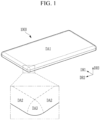
- FIG. 1 is a schematic perspective view of a display device according to some exemplary embodiments.
- FIG. 2 is a view depicting a shape of a round corner of a display device according to some exemplary embodiments.
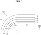
- FIG. 3 is a schematic cross-sectional view of a display device according to some exemplary embodiments.
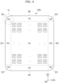
- FIG. 4 is a plan layout view of a display device according to some exemplary embodiments.
- FIG. 5 is an enlarged view of a part of the display device shown in FIG. 4 according to some exemplary embodiments.
- FIG. 6 is a plan exploded view of a corner before bending an edge region of the display device shown in FIG. 4 according to some exemplary embodiments.
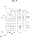
- FIG. 7 is a plan exploded view of a corner including an arrangement of display units before bending an edge region of a display device according to some exemplary embodiments.
- a display device 1000 includes a display area for displaying an image, and the display area includes a display surface.
- the display area when viewing in a third direction DR3, includes a front display area DA1 disposed on a front surface, a side display area DA2 respectively disposed on at least two sides of the front display area DA1, and a corner display area DA3 disposed in the corner of the front display area DA1.
- the front display area DA1 is disposed at the center or central area of the display device 1000, and the side display area DA2 and the corner display area DA3 are disposed at the edge region of the display device 1000. In this manner, the side display area DA2 and the corner display area DA3 are disposed around the front display area DA1.
- the front display area DA1 may occupy the widest area in the entire display area, and may have a substantially flat display surface.
- the overall shape of the front display area DA1 in a plan view may be a rectangle having four sides, but is not limited thereto.
- the corners of the front display area DA1 may be sharp as shown or round.
- the four sides of the front display area DA1 may be extended to be parallel to the first direction DR1 or the second direction DR2, respectively.
- the side display area DA2 may include four regions respectively connected to four sides of the top, bottom, left, and right sides of the front display area DA1, but may include only some of them.
- the display surface of each side display area DA2 may form the bent surface, and a curvature may be constant or different depending on positions of the bent surface.
- Each side display area DA2 may have a shape that is substantially similar to a part (e.g., one fourth (1/4)) of the side surface of a curved column, such as an elliptical or circular cylinder.
- the corner display area DA3 is formed on four corners or some corners of the display device 1000, and is disposed between two adjacent side display areas DA2.
- the display surface of each corner display area DA3 forms the bent surface, and the curvature may be constant or different depending on positions of the bent surface.
- the shape of the bent surface of the corner display area DA3 is different from the shape of the bent surface of the side display area DA2.
- each corner display area DA3 may have a shape that is similar to a part (e.g., one eighth (1/8)) of a curved body, such as a substantially spherical or elliptical sphere.
- the position on the display surface (also referred to as the bent surface) of the corner display area DA3 may be represented by a polar coordinate system with a curvature radius r based on an origin O, an angle ⁇ (referred to as a poloidal angle with a unit of a radian), and an angle ⁇ (referred to as an azimuth angle with a unit of a radian).
- the angle ⁇ is the angle between the third direction DR3, and the line from the origin O to the position on the display surface.
- the angle ⁇ is the angle between the first direction DR1, and a projection of the line from the origin O to the position on the display surface onto the xy plane.
- the xy plane is a plane formed by the first direction DR1 and the second direction DR2.
- the curvature radius r may be constant or may vary depending on the position on the bent surface or display surface of the corner display area DA3.
- the display device 1000 may include a display panel 10, a polarization layer 20, an adhesive layer 30, and a cover window 40, which are sequentially stacked in a cross-sectional view.
- the display panel 10 may include an electrical device, such as a plurality of pixels, each of which is a unit capable of displaying the image, and a plurality of signal lines, and may include a flexible substrate. Each pixel may include at least one transistor.
- the display panel 10 may further include a touch sensor layer capable of sensing an external touch.
- the touch sensor layer may include a plurality of touch electrodes. It is also contemplated that a separate touch sensor layer may be, additionally or alternatively, disposed between the display panel 10 and the polarization layer 20.
- the polarization layer 20 may be in a form of a flexible film, and may prevent (or at least reduce) external light reflected from various electrodes or wiring included in the display panel 10 from being visible.
- the polarization layer 20 may be a circular polarizer, in which case the polarization layer 20 may include a linear polarizer and a quarter-wavelength plate.
- the cover window 40 may be made of an insulating material, such as transparent plastic or glass.
- the cover window 40 may be attached to the polarization layer 20 through an adhesive layer 30, such as optically clear adhesive (OCA), optically clear resin (OCR), pressure-sensitive adhesive (PSA), and/or the like.
- OCA optically clear adhesive
- OCR optically clear resin
- PSA pressure-sensitive adhesive
- the display device 1000 is substantially flat in the front display area DA1 and curved with the curvature in the side display area DA2 and the corner display area DA3 to form the bent surface.
- the bent curvature that is, the curvature radius r, may be constant or variable depending on the position.
- the curved display area is referred to as a curved display area DAr.
- the curved display area DAr includes the side display area DA2 and the corner display area DA3.
- the display panel 10 may include a curved edge region 10r
- the polarization layer 20 may include a curved edge region 20r
- the cover window 40 may include a curved edge region 40r.
- a display device 1000a is substantially the same as most of the display device 1000.
- the display device 1000a includes the front display area DA1 and the side display area DA2, and the corner display area DA3 disposed at at least two sides of the front display area DA1.
- the side display area DA2 and the corner display area DA3 are bent with the curvature as described above to form the bent surface.
- the corner display area DA3 is capable of stretching and/or shrinking as a whole. That is, the corner display area DA3 is stretched or shrunk depending on a force applied thereto.
- the side display area DA2 is stretched and/or shrunk to the same degree as the corner display area DA3 as a whole, or may have a lower stretching force and/or shrinkage force than the corner display area DA3.
- the front display area DA1 may have the stretching force and/or shrinkage force of the same degree as the corner display area DA3 or the side display area DA2, or may have a lower stretching force and/or shrinkage force than the corner display area DA3 or the side display area DA2.
- the front display area DA1 may have a fixed shape or the flexible characteristic such that it is bendable, or may not have substantial stretching and/or contracting forces as the area is stretched or shrunk.
- the front display area DA1, the side display area DA2, and the corner display area DA3 include a plurality of display units UT.
- Each display unit UT may be a pixel that may represent one of the primary colors of red, green, and blue, or a unit group that includes a plurality of pixels.
- the unit group may include a plurality of pixels representing different primary colors from each other, for example red pixels, green pixels, and blue pixels.
- the display unit UT may be repeatedly arranged in at least one direction. For instance, FIG. 4 shows an example in which a plurality of display units UT are arranged in the first direction DR1 and the second direction DR2.
- a plurality of display units UT are disposed in the side display area DA2 and the corner display area DA3, as well as the front display area DA1.
- the arrangement shape of the plurality of display units UT in the front display area DA1 may be the same as or different from the arrangement shape of the plurality of display units UT in the side display area DA2 or the corner display area DA3.
- the arrangement shape of the plurality of display units UT in the corner display area DA3 is different from that of an arrangement shape of a plurality of display units UT in the side display area DA2 or the front display area DA1.
- the edge as the edge sides of the display device 1000a may include edges ED1 and ED2 as the edge side of the side display area DA2 and an edge ED3 as the edge side of the corner display area DA3.
- Each of the edges ED1 and ED2 of the side display area DA2 may be a straight line substantially extending in the first direction DR1 or the second direction DR2, and the edge ED3 of the corner display area DA3 may be substantially a curved line.
- the edge ED3 of the corner display area DA3 may be in the form of an arc shape that is part of a circle of which the curvature radius (or radius of curvature) is constant or varied. Both ends of the edge ED3 may be connected to the edges ED1 and ED2 of two side display areas DA2, respectively.
- the boundary between the side display area DA2 and the front display area DA1 may also be substantially straight, and the corner display area DA3 may be connected to the corner of the front display area DA1.
- the front display area DA1 and the side display area DA2 may include one physically continuous substrate and layers stacked thereon, or separate substrates and layers stacked thereon.
- the corner display area DA3 and the side display area DA2 and/or the front display area DA1 may include the substrate or the stacked layers that are physically continuous with the side display area DA2 and/or the front display area DA1, or the separate substrates and stacked layers.
- the edge ED3 may be physically and continuously connected with the edges ED1 and ED2.
- the front display area DA1 and the side display area DA2 contain separate substrates and stacked layers, two substrates and stacked layers may be bonded together, and when the corner display area DA3 and the side display area DA2 include separate substrates and stacked layers, two substrates and the stacked layers may be bonded together.
- the curvature radius of the side display area DA2 and the corner display area DA3 is denoted by r, and the length of the edge ED3 of the corner display area DA3 may be approximately ⁇ r/2.
- the distance on the bent surface from the edges ED1 and ED2 to the boundary between the front display area DA1 and the side display area DA2 (hereinafter, simply referred to as a boundary of the front display area DA1) may be approximately ⁇ r/2, for example as indicated in Fig. 5 .
- FIG. 6 shows an exploded view on a two-dimensional plane as a drawing for the corner AA of a display device 100a before bending the side display area DA2 and the corner display area DA3 of the display device 1000a described above into the bent surface. That is, the side display area DA2 and the corner display area DA3 described in association with FIG. 6 are flat and unfolded before being formed into the bent surface. If the state is subsequently changed to be an unfolded state, it means that the edge region of the display device is in a state before being bent into the bent surface, or in a state in which the bent surface is stretched and contracted again.
- the length of the edge EG3 of the corner display area DA3 may be approximately ⁇ r/2, and the plan distance from the edges EG1 and EG2 of the side display area DA2 to the boundary between the front display area DA1 and the side display area DA2 may be approximately r.
- ED1, ED2, and ED3 represent the edges of the side display area DA2 and the corner display area DA3 in the state that the side display area DA2 and the corner display area DA3 as the edge region of the display device 1000a are bent as the bent surface
- EG1, EG2 and EG3 represent the edges of the side display area DA2 and the corner display area DA3 in the state that the side display area DA2 and the corner display area DA3 are unfolded before being bent in the display device 100a.
- the lengths of the edge ED3 of the corner display area DA3 in the unfolded state and the edge EG3 of the corner display area DA3 in the bent surface may all be approximately ⁇ r/2.
- the distance from the edge EG3 of the corner display area DA3 of the unfolded state to the boundary of the front display area DA1 is the same as the curvature radius r; however, the distance on the bent surface from the edge ED3 of the corner display area DA3 to the boundary of the front display area DA1 after the bent surface is formed may be ⁇ r/2 as above-described, for example indicated in Fig. 5 .
- the distance from the edges EG1 and EG2 of the side display area DA2 of the unfolded state to the boundary of the front display area DA1 is the same as the curvature radius r; however, the distance on the bent surface from the edges ED1 and ED2 of the side display area DA2 of the curved bent surface to the boundary of the front display area DA1 may be ⁇ r/2 as above-described, for example indicated in Fig. 5 .
- the side display area DA2 and the corner display area DA3 are stretched from the front display area DA1 in the outer direction.
- the side display area DA2 disposed at the left based on the front display area DA1 is stretched to the left
- the side display area DA2 disposed on the upper side is stretched upward
- the corner display area DA3 is stretched outward in the radial direction as indicated by the arrows extending from the edges EG1, EG2, and EG3.
- the distance (a shortest distance) from each edge EG1, EG2, and EG3 to the boundary of the front display area DA1 on the bent surface starts from distance r and is stretched to distance ⁇ r/2, as shown in FIG. 5 , in the curved and bent surface, and the side display area DA2 and the corner display area DA3 having the display surface as the bent surface may be formed. That is, in the side display area DA2 and the corner display area DA3, the area thereof is stretched in the process in which the edge region of the display device 100a is bent to form the display device 1000a.
- the distance between the display units UT and/or the area of the display units UT may be different from the state that the side display area DA2 and the corner display area DA3 are formed of the bent surface.
- a pitch Wb1 (an arrangement pitch of adjacent display units UT) in the first direction DR1 of the display units UT in the side display area DA2 adjacent to the front display area DA1 in the first direction DR1 may be smaller than a pitch Wa1 in the first direction DR1 of the display units UT in the front display area DA1.
- the pitch Wb1 may be constant.
- the pitch Wb1 may be approximately 1/( ⁇ /2) of the pitch Wa1, that is, 2/ ⁇ .
- the pitch Wb2 in the second direction DR2 of the display units UT may be the same as the pitch Wa2 in the second direction DR2 of the display units UT in the front display area DA1.
- the distance (in the first direction DR1) between the adjacent display units UT in the side display area DA2 may also be smaller than the distance (in the first direction DR1) between the adjacent display units UT in the front display area DA1.
- the pitch Wc2 in the second direction DR2 of the display units UT in the side display area DA2 adjacent to the front display area DA1 in the second direction DR2 may be smaller than the pitch Wa2 in the second direction DR2 of the display units UT in the front display area DA1.
- the pitch Wc2 may be constant.
- the pitch Wc2 may be approximately 1/( ⁇ /2) of the pitch Wa2, that is, 2/ ⁇ .
- the pitch Wc1 in the first direction DR1 of the display units UT in the side display area DA2 adjacent to the front display area DA1 in the second direction DR2 may be the same as the pitch Wa1 in the first direction DR1 of the display units UT in the front display area DA1.
- the distance (in the second direction DR2) between the adjacent display units UT in the side display area DA2 may also be smaller than the distance (in the second direction DR2) between the adjacent display units UT in the front display area DA1.
- the display units UT may be arranged to form a plurality of rows (also referred to as columns) Ur disposed radially.
- Each column Ur may be a column formed in a radial direction, that is, a direction elongated toward the edge of the corner display area DA3 from the corner of the front display area DA1.
- the display units UT may be further disposed between the adjacent columns Ur.
- the pitch Wr in the radial direction of the display units UT in the corner display area DA3 may be smaller than the pitch Wa1 or the pitch Wa2 of the display units UT in the front display area DA1.
- the pitch Wr may be the same as the pitch Wb1 in the first direction DR1 of the display units UT disposed in the side display area DA2 adjacent to the front display area DA1 in the first direction DR1 or the pitch Wc2 in the second direction DR2 of the display units UT disposed in the side display area DA2 adjacent to the front display area DA1 in the second direction DR2.
- the pitch Wr may be constant.
- the pitch Wr may be approximately 1/( ⁇ /2) of the pitch Wa1 or the pitch Wa2, that is, 2/ ⁇ .
- the distance (in the radial direction) between the adjacent display units UT may also be smaller than the distance (in the first direction DR1 or the second direction DR2) between the adjacent display units UT in the front display area DA1.
- the pitch of the display units UT in the side display area DA2 on the bent surface or the display surface may be almost the same as the pitch of the display units UT in the front display area DA1 on the bent surface or the display surface.
- the resolution of the display units UT of the side display area DA2 and the corner display area DA3 may be larger than the resolution of the display units UT of the front display area DA1, but after the side display area DA2 and the corner display area DA3 are stretched to form the bent surface, the resolution on the bent surface or the display surface of the display units UT of the side display area DA2 and the corner display area DA3 may be similar to the resolution of the display units UT of the front display area DA1.
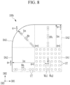
- FIG. 8 is a plan exploded view of a corner including an arrangement of display units before bending an edge region of a display device according to some exemplary embodiments.
- a display device 100b shown in FIG. 8 as the display device 100b in the unfolded state before the edge region of the display device 1000b is formed as the bent surface is the same as most of the display device 100a described in association with FIG. 7 ; however, the pitch of the display units UT may be changed depending on a position in the side display area DA2 and/or the corner display area DA3.
- the pitch of the display units UT in the side display area DA2 and/or the corner display area DA3 may become gradually smaller according to the outer direction Drt. For instance, the pitch of the display units UT in the side display area DA2 and the corner display area DA3 may become larger with an increasing distance from the edges EG1, EG2, and EG3.
- the pitch Wb in the first direction DR1 of the display units UT in the side display area DA2 adjacent to the front display area DA1 in the first direction DR1 may be smaller than the pitch Wa1 in the first direction DR1 of the display units UT in the front display area DA1, and may become gradually smaller in association with the outer direction Drt.
- the pitch Wc in the second direction DR2 of the display units UT in the side display area DA2 adjacent to the front display area DA1 in the second direction DR2 may be smaller than the pitch Wa2 in the second direction DR2 of the display units UT in the front display area DA1, and may become gradually smaller in association with the outer direction Drt.
- the pitch Wr in the outer direction Drt or the radial direction of the display units UT in the corner display area DA3 may be smaller than the pitch Wa1 in the first direction DR1 of the display units UT and/or the pitch Wa2 in the second direction DR2 of the display units UT in the front display area DA1, and may become gradually smaller in association with the outer direction Drt.
- the distance between the adjacent display units UT in the side display area DA2 and/or the corner display area DA3 may become gradually smaller according to the outer direction Drt.
- the polar angle ⁇ of each position is from 0 to ⁇ /2
- the pitches Wb, Wc, and Wr in the outer direction Drt of the display units UT in the unfolded state may be changed depending on the corresponding polar angle ⁇ after the bending process.
- the pitches Wb, Wc, and Wr in the outer direction Drt of the display units UT in the side display area DA2 and the corner display area DA3 as a function of the corresponding polar angle ⁇ may be changed with a ratio of ln(1/cos ⁇ ) in the opposite direction to the outer direction Drt.
- the ratio of the pitches Wb, Wc, and Wr at the position where the polar angle ⁇ is ⁇ /6 and the pitches Wb, Wc, and Wr at the position where the polar angle ⁇ is ⁇ /3 may be approximately ln(1/cos ⁇ /3):ln(1/cos ⁇ /6) in sequence.
- the ratio (ln(1/cos ⁇ )) be derived from Equation 1 for a stretch ratio ( ⁇ ) of the distance (r ⁇ sin ⁇ ) on the bent surface where the distance (r ⁇ ) is extended in the exploded view based on the origin O in the drawing shown in FIG. 2 described above.
- FIG. 9 is a plan layout view of a display device according to some exemplary embodiments.
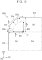
- FIG. 10 is a view showing a shape before forming a bent surface and after forming a bent surface in the display device shown in FIG. 9 according to some exemplary embodiments.
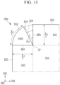
- FIGS. 11 , 12 , and 13 are plan exploded views of a part of a display device before forming a bent surface and after forming a bent surface in a display device according to various exemplary embodiments.
- a display device 1000b is the same as most of the display device 1000; however, the display area includes a front display area DA4, a side display area DA5, and a corner display area DA6.
- the display areas DA4, DA5, and DA6 may be the same as the shape and arrangement of the display areas DA1, DA2, and DA3 described above, respectively.
- the corner display area DA6 is capable of stretching and/or shrinking; however, the side display area DA5 may have a lower stretching and/or shrinking force than the corner display area DA6, and may have a stretching and/or shrinking force of the same degree as the front display area DA4.
- the front display area DA4 and the side display area DA5 may have a fixed shape or a flexible characteristic such that they may be bent, but they may have little stretching force and/or shrinking force in which the area is stretched or shrunk.
- the pitch of the display units UT disposed in the side display area DA5 may be the same as or similar to the pitch of the display units UT disposed in the front display area DA4.
- the pitch of the display units UT disposed at (or in) the corner display area DA6 at which some regions are stretched may be smaller than the pitch of the display units UT of the front display area DA4 before the stretching of the corner display area DA6, and may vary depending on the position.
- the variation ratio may be the same as described in association with FIG. 8 .
- the display device 1000b Before the edge region of the display device 1000b according to some exemplary embodiments shown in FIG. 9 becomes the bent surface, the display device may be the same as the various exemplary embodiments described in association with FIGS. 10 to 13 according to the corner display area DA6.
- the display device 1000b may include the edges ED4 and ED5 as the edges of the side display area DA2, and the edge ED3a as the edge of the corner display area DA6.
- the edge ED3a may be the same as the edge ED3 of the display device 1000a, and the edges ED4 and ED5 may be the same as the above-described edges ED1 and ED2.
- the corner display area before being formed of the bent surface is denoted by DA6a.
- the front display area DA4 and the side display area DA5 may include one substrate and stacked layers physically continuous to each other, and the corner display areas DA6 and DA6a may include separate substrates and stacked layers physically separated from the front display area DA4 and the side display area DA5 and may be bonded to the substrate and the stacked layers of the front display area DA4 and the side display area DA5.
- corner display areas DA6 and DA6a are separated from the side display area DA5 on most of the boundary between the side display area DA5 and the corner display areas DA6 and DA6a and include the substrates and stacked layers bonded to each other, the corner display areas DA6 and DA6a may include the substrate and stacked layers that are physically and continuously connected to the front display area DA4 on a connection point CP as the boundary between the corner display areas DA6 and DA6a and the front display area DA4.
- the corner display areas DA6 and DA6a include the same substrate and stacked layers as the front display area DA4 and the side display area DA5, however, the corner display areas DA6 and DA6a and the side display area DA5 may be separated from each other on the boundary with the side display area DA5 and may be connected to the front display area DA4 with the continuous substrate and stacked layers through the connection point CP.
- the connection point CP may be a region having a certain area rather than a dot.
- the continuous substrate and stacked layers may be cut along boundaries DB1 and DB2 to separate the substrate and stacked layers as previously described, but may remain as the continuous substrate and stacked layers in the connection point CP.
- the edge ED3a is connected to the edges ED4 and ED5, but may be in a bonded state. Wiring that may supply the signals to the corner display areas DA6 and DA6a (e.g., supply signals to the display units UT) can pass at the connection point CP.
- the length of the edge EG3a before the stretched state may be ⁇ r/2, and the length of the side of the corner display area DA6a forming the boundary with the side display area DA5 may approximately be the curvature radius r.
- the distance from the boundary of the front display area DA4 to the edge ED5 of the side display area DA5 is approximately ⁇ r/2, and this length may be bent at it is to form the bent surface.
- the length of the radial direction from the connection point CP of the corner display area DA6a starts from r is extended in the arrow direction shown in FIG. 10 , and becomes approximately ⁇ r/2 in the bent surface state.
- the corner display area DA6 as stretched may be bonded to the side display area DA5 to be fixed in the state of forming the bent surface.
- the edge region may be bent to have the bent surface of the same shape as the display device 1000b described in association with FIG. 9 .
- the display device 100c in the unfolded state is the same as most of the unfolded state of the display device 1000b described in association with FIG. 10 ; however, the corner display area DA6b may be different.
- the corner display area DA6b is continuously connected to the side display area DA5 even in the unfolded state, and the edge EG3b of the corner display area DA6b is continuously connected with the edges EG4 and EG5 of the side display area DA5.
- the substrate and stacked layers of the corner display area DA6b may be continuously connected to the substrate and stacked layers of the side display area DA5 and the front display area DA4.
- the side display area DA5 of the display device 100c When the side display area DA5 of the display device 100c is bent into the bent surface, the side display area DA5 is not substantially stretched and is bent while the distance from the boundary of the front display area DA4 to the edges EG4 and EG5 of the side display area DA5 is maintained at approximately ⁇ r/2, thereby, having the distance of approximately ⁇ r/2 even when it is the bent surface.
- the length of the edge EG3b of the corner display area DA6b is ( ⁇ /2) 2 r, and in the state that the corner display area DA6b is bent to form the bent surface, the length is ⁇ r/2 as shown in FIG. 2 or FIG. 10 . That is, when the corner display area DA6b starts from the unfolded state and is bent to form the bent surface, the length of the edge EG3b may be reduced from ( ⁇ /2) 2 r to ⁇ r/2.
- the corner display area DA6b may be bent in the bent surface as shown in FIG. 2 from the flat state on the two-dimensional flat structure shown in FIG. 11 .
- the edge region may be bent so that a display device 100d according to some exemplary embodiments has the bent surface of the same shape as the display device 1000b described in association with FIG. 9 .
- the display device 100d in the unfolded state before the edge region forms the bent surface is the same as most of the display device 100c described in association with FIG. 10 , but the corner display area DA6c may be different.
- the corner display area DA6c does not need to be stretched, and thus, may not be the stretchable region. That is, the corner display area DA6c may not be stretchable like the side display area DA5 and the front display area DA4. However, the corner display area DA6c may be stretchable.
- the corner display area DA6c may be physically and continuously connected or bonded to one of two neighboring side display areas DA5 in the unfolded state to form the boundary BD3.
- the edge EG7 of the corner display area DA6c is continuously connected to the edge EG5 of the side display area DA5 to which the corner display area DA6c is connected.
- the length of the edge EG7 of the corner display area DA6c may be approximately ⁇ r/2.
- the corner display area DA6c further includes the edge EG6 facing the boundary BD4 of the side display area DA5 which it is not connected.
- the edge EG6 is disconnected from the edge EG7 and separated from the side display area DA5 in the unfolded state.
- the edge EG6 may be a smooth curved line (e.g., arcuately formed) without a straight line; however, exemplary embodiments are not limited thereto.
- the increased distance dL (meaning the shortest distance in the vertical direction to the imaginary straight line) from the virtual straight line to the edge EG6 may be different depending on the position of the edge EG6, and for example, it may be determined according to Equation 2 with reference to FIG. 2 .
- dL / r ⁇ ⁇ ⁇ / 2 sin ⁇
- the distance between the edge EG6 and the virtual straight line may be greatest in the middle of the edge EG6.
- the length of the edge EG6 of the corner display area DA6c may be approximately ⁇ r/2.
- the edge EG6 of the corner display area DA6c may be bent to form the bent surface in three dimensions without contraction or stretching to meet the boundary BD4 of the side display area DA5 and the edge EG6 and the boundary BD4 to be bonded to each other.
- the shape of the display device in which the bent surface is formed may have the same shape as the display device 1000b described in association with FIGS. 9 and 10 . In this manner, the separate substrate and the stacked layers along the edge EG6 may be bonded to the separate substrate and the stacked layers along the boundary BD4.
- the edge region may be bent so that a display device 100e according to some exemplary embodiments has the bent surface of the same shape as the display device 1000b as described in association with FIG. 9 .
- the display device 100e in the unfolded state before the edge region forms the bent surface is the same as most of the display device 100d described in association with FIG. 12 , but the corner display area DA6d may be different.
- the corner display area DA6d is stretchable so that the area may be increased when the corner display area DA6d forms the bent surface.
- the corner display area DA6d may be continuously and physically connected or bonded to one of two neighboring side display areas DA5 in the unfolded state to form the boundary BD3.
- the edge EG8 of the corner display area DA6d is continuously connected to the edge EG5 of the side display area DA5 to which the corner display area DA6d is connected.
- the length of the edge EG8 of the corner display area DA6d may be approximately ⁇ r/2.
- the corner display area DA6d further includes the edge EG9 facing the boundary BD4 of the side display area DA5 which it is not connected.
- the edge EG9 is connected with the edge EG8 and is separated from the side display area DA5 in the unfolded state.
- the edge EG9 may be a straight line connecting from the connection point CP to the end of the edge EG8, unlike the above-described edge EG6, which was arcuately formed.
- the edge EG9 When the corner display area DA6d is stretched to form the bent surface, the edge EG9 may be stretched or form a new edge ED9 in three dimensions.
- the edge ED9 may be the curved line configuration.
- the increased distance (dLa) (which means the shortest distance in the direction perpendicular to the edge EG9 from the edge EG9 before the stretching to the edge ED9 of the curved line) may vary depending on the position, and for example, may be determined according to Equation 2 described above with reference to FIG. 12 . That is, the distance dLa may be determined in the same manner as the distance dL.
- the length of the new edge ED9 may be approximately ⁇ r/2.
- the edge ED9 meets the boundary BD4 of the side display area DA5, and the edge ED9 and the boundary BD4 may be connected to each other.
- the shape of the display device in which the bent surface is formed may have the same shape as the display device 1000b described in association with FIGS. 9 and 10A.
- the display device having the corner display areas DA3 and DA6 capable of displaying the image may be provided by also rounding the corner of the display devices 1000a and 1000b, and the shape of the rounded corner display areas DA3 and DA6 may be enhanced.
- a display device 1000c according to an exemplary embodiment is described with reference to FIG. 14 .
- FIG. 14 is a plan layout view of a display device according to some exemplary embodiments.
- the display device 1000c may be the same as the display device (e.g., each of the display devices of the shape forming the bent surface or the shape before forming the bent surface) as previously described; however, the front display area DA9 corresponding to the above-described front display areas DA1 and DA4 and surrounding the display area DA10 corresponding to the above-described side display areas DA2 and DA5 and corner display areas DA3 and DA6 may be further included.
- the corner CN of the front display area DA9 may be rounded rather than pointed (or formed as a vertex).
- the shape of the corner CN of the display device 1000c in which the surrounding display area DA10 constitutes the bent surface may have a bent (e.g., perfectly bent surface) and the boundary between the surrounding display area DA10 and the front display area DA9 may have a more perfectly round shape, and, as such, there may be no part recognized as an edge between the front display are DA9 and the surrounding display area DA10.
- FIGS. 15 and 16 a method for manufacturing a display device according to some exemplary embodiments will be described with reference to FIGS. 15 and 16 .
- the method for laminating the display panel with a cover window is described.
- the polarization layer 20 shown in FIG. 3 is omitted for convenience.
- FIG. 15 is a lateral view showing a process of a manufacturing method of a display device according to some exemplary embodiments.
- FIG. 16 is a lateral view showing an additional process of the manufacturing method in FIG. 15 according to some exemplary embodiments.
- a laminate device may include a pad unit including a shape pad 300 and an edge pad 350a disposed at the edge of the shape pad 300.
- a pad unit including a shape pad 300 and an edge pad 350a disposed at the edge of the shape pad 300.
- one or more jigs may be disposed under the pad unit.
- the elastic coefficient of the edge pad 350a (also known as the modulus) is lower than the elastic coefficient of the shape pad 300 so that the shape of the edge pad 350a may be more varied, e.g., may be more varied under load.
- the edge pad 350a may be formed along the edge of the top portion of the shape pad 300.
- the edge pad 350a may include an air pump or may be connected to an air pump so that the shape and volume of the edge pad 350a may vary depending on the air pressure.
- the display panel 10 After attaching an adhesive sheet 50 to the underside of the display panel 10, the display panel 10 is disposed on the pad unit.
- the adhesive sheet 50 may be pulled in the downward direction F1 so that the edge pad 350a has a minimum (or at least decreased) volume.
- the edge region of the display panel 10 may not substantially extend, and an edge region 10ra constituting the bent surface may be formed. If the edge pad 350a includes an air pump or is connected to an air pump, the edge pad 350a may be in a state of a minimum volume at a minimum air pressure.
- the cover window 40 may include an edge region 40r that is bent to form the bent surface.
- the central portion of the display panel 10 on the shape pad 300 may first come in contact with the adhesive layer 30.
- the central portion of the display panel 10 in contact with the adhesive layer 30 may correspond to the above-described front display areas DA1 and DA4.
- the direction of the adhesive sheet 50 may be adjusted so that the edge region 10ra of the display panel 10 is not in contact with the adhesive layer 30 under the cover window 40.
- the volume of the edge pad 350a is increased to be an increased edge pad 350.
- the direction F2 of pulling the adhesive sheet 50 may be adjusted so that the volume of the edge pad 350a may be increased.
- the edge region 10ra of the display panel 10, which has not yet contacted the adhesive layer 30, may be stretched to form the edge region 10r that forms the bent surface of the side display areas DA2 and DA5 and the corner display areas DA3 and DA6 of the above-described several exemplary embodiments.
- the edge pad 350a includes an air pump or is connected to the air pump, the volume of the edge pad 350a may be increased by increasing the air pressure.
- the edge region 10r of the display panel 10 comes in contact with the adhesive layer 30, so that the entire display panel 10 may be bonded to the window 40 through the adhesive layer 30.
- the shape of the edge region 10r of the display panel 10 may have the bent surface according to the several examples described above. Thereafter, the adhesive sheet 50 may be removed.
- FIGS. 17 and 18 An example of the display units UT disposed in the display area of the display devices according to various exemplary embodiments will be described with reference to FIGS. 17 and 18 .
- FIG. 17 is a layout view of pixels of a display area of a display device according to some exemplary embodiments.
- FIG. 18 is a layout view of pixels of a display area of a display device according to some exemplary embodiments.
- FIG. 17 shows an example of the display unit UT to be disposed in the display area DAg where the stretching and/or shrinking need not be possible in the above-described several exemplary embodiments, for example, the front display area DA1 and DA4 or the side display area DA5.
- the display area DAg includes the substrate 110a, and the substrate 110a may be flexible or rigid, but may not be substantially stretched and/or shrunk.
- the display unit UT may be the pixels R, G, and B, each of which may emit light of one primary color as described above, or a plurality of pixels R, G, and B representing different primary colors.
- FIG. 18 shows an example of the display unit UT to be disposed in the display area DAs that may be stretched and/or shrunk in the several above-described exemplary embodiment, for example the corner display areas DA3 and DA6 or the side display area DA2.
- the display area DAs includes the substrate 110b and the substrate 110b is capable of stretching and/or shrinking structurally or materially.
- the substrate 1 10b which is structurally stretchable and/or shrinkable, as shown in FIG. 18 , may include a plurality of main units (or portions) 111 and a plurality of bridges BR connecting the adjacent main units 111 to each other.
- Each bridge BR may be bent with a variety of curvature radiuses and may be easily flexed, and if a force is applied to the display area DAs, the substrate 110b of the display area DAs can be easily stretched and/or retracted without damage to the main unit 111.
- the shape of the bridge BR changes and the main unit 111 itself may rotate and/or be displaced (e.g., translate) without deformation.
- each main unit 111 a plurality of pixels R, G, and B may be disposed.
- the display unit UT may be one main unit 111 or one pixel R, G, or B.
- FIGS. 19 to 23 A peripheral area of the display device according to the several exemplary embodiments will be described with reference to FIGS. 19 to 23 along with the above-described drawings.
- FIG. 19 is a schematic perspective view and a cross-sectional view of a display device according to some exemplary embodiments.
- the display device 1000d is the same as most of the display devices 1000, 1000a, 1000b, and 1000c; however, the shape of the bent surface of the peripheral area including the side display area DA2 and the corner display area DA3 may be different.
- the angle ⁇ formed by the bent surface of the side display area DA2 and the corner display area DA3 with respect to the origin O may be greater than or equal to 0 degrees and less than or equal to 90 degrees.
- FIG. 19 shows an example in which the angle ⁇ is larger than 0 degrees and smaller than 90 degrees.
- the angle ⁇ corresponding to the part from the point PT where the line LA meets the edge of the display device 1000d to the boundary between the side display area DA2 / the corner display area DA3 and the front display area DA1 may be more than 0 degrees to less than 90 degrees.
- FIG. 20 is a schematic perspective view and a cross-sectional view of a display device according to some exemplary embodiments.
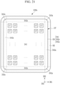
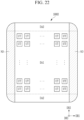
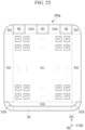
- FIGS. 21 to 23 are plan layout views of a display device according to various exemplary embodiments.
- the display devices according to the various exemplary embodiments shown in FIGS. 20 to 23 are the same as most of the display devices 1000, 1000a, 1000b, 1000c, and 1000d; however, only part among the side display area DA2 and the corner display area DA3 may be included in the display area for displaying the image.
- the display device 1000e only part of the above-described side display area DA2 and part of the above-described corner display area DA3 is the display area displaying the image to be the side display area DA2a and the corner display area DA3a, and the rest of the region may be a non-display area ND.
- the side display area DA2a and the corner display area DA3a may be adjacent to the front display area DA1 based on the boundary DT, and the outer region adjacent to the edge of the display device 1000e may be the non-display area ND.
- the angle ⁇ formed by the bent surface of the side display area DA2a and the corner display area DA3a with respect to the origin O may be greater than 0 degrees and less than 90 degrees when viewing the section of the display device 1000e along the line LA. That is, on the bent surface of the side display area DA2a and the corner display area DA3a, the angle ⁇ corresponding to the part from the point where the line LA meets the boundary DT to the boundary between the side display area DA2a / corner display area DA3a and the front display area DA1 may be greater than 0 degrees and less than 90 degrees.
- the front display area DA1, the side display area DA2a, and the corner display area DA3a in one display device 1000e may form one continuous display area DD.
- the non-display area ND may have a shape surrounding the surroundings of the display area DD.
- FIG. 22 shows an example of a display device 1000f in which the side display area DA2 and the entire corner display area DA3 disposed on the left and the right based on the front display area DA1 are included in the non-display area ND, and, as such, do not display the image. That is, the front display area DA1 and the side display area DA2 disposed on the top and bottom sides of the front display area DA1 can form one continuous display area.
- a plurality of separated side display areas DA2b may be disposed on one side or a plurality of sides of the front display area DA1, and the non-display area ND may be disposed between the adjacent side display areas DA2b or between the side display area DA2b and the corner display area DA3.
- FIG. 23 shows an example in which the side display area DA2c and the corner display area DA3b are disposed downward based on the front display area DA1, and the non-display area ND is disposed outside of the side display area DA2c and the corner display area DA3b.
- the side display area DA2c and the corner display area DA3b may be disposed adjacent to the front display area DA1, and the non-display area ND may be disposed outside and adjacent to the edge of the display device 1000g.
Landscapes
- Engineering & Computer Science (AREA)
- Physics & Mathematics (AREA)
- Theoretical Computer Science (AREA)
- General Physics & Mathematics (AREA)
- Microelectronics & Electronic Packaging (AREA)
- Computer Hardware Design (AREA)
- Optics & Photonics (AREA)
- Chemical & Material Sciences (AREA)
- Crystallography & Structural Chemistry (AREA)
- General Engineering & Computer Science (AREA)
- Human Computer Interaction (AREA)
- Nonlinear Science (AREA)
- Geometry (AREA)
- Mathematical Physics (AREA)
- Devices For Indicating Variable Information By Combining Individual Elements (AREA)
- Liquid Crystal (AREA)
- Electroluminescent Light Sources (AREA)
- Measuring Pulse, Heart Rate, Blood Pressure Or Blood Flow (AREA)
- Vehicle Body Suspensions (AREA)
- Diaphragms For Electromechanical Transducers (AREA)
Claims (12)
- Anzeigevorrichtung, umfassendeinen vorderen Anzeigebereich (DA1); undeine Vielzahl von seitlichen Anzeigebereichen (DA2); undeinen Eckanzeigebereich (DA3),wobei die Vielzahl der seitlichen Anzeigebereiche (DA2) und der Eckanzeigebereich (DA3) außerhalb des vorderen Anzeigebereichs (DA1) angeordnet sind,wobei die Vielzahl der seitlichen Anzeigebereiche (DA2) Folgendes umfasst:einen ersten seitlichen Anzeigebereich (DA2), der an einer ersten Seite des vorderen Anzeigebereichs (DA1) angeordnet ist; undeinen zweiten seitlichen Anzeigebereich (DA2), der an einer zweiten Seite des vorderen Anzeigebereichs (DA1) angeordnet ist,wobei der Eckanzeigebereich (DA3) an einer Ecke des vorderen Anzeigebereichs (DA1) zwischen dem ersten seitlichen Anzeigebereich (DA2) und dem zweiten seitlichen Anzeigebereich (DA2) angeordnet ist, wobei der Eckanzeigebereich (DA3) mit dem ersten seitlichen Anzeigebereich (DA2) und dem zweiten seitlichen Anzeigebereich (DA2) verbunden ist, undwobei:der Eckanzeigebereich (DA3) streckbar und/oder schrumpfbar ist, wobei der erste seitliche Anzeigebereich (DA2) und der zweite seitliche Anzeigebereich (DA2) streckbar und/oder schrumpfbar sind, und wobei:der vordere Anzeigebereich (DA1) eine flache Anzeigefläche aufweist;der erste seitliche Anzeigebereich (DA2), der zweite seitliche Anzeigebereich (DA2) und der Eckanzeigebereich (DA3) jeweils eine gebogene Oberfläche bilden;eine Form der gebogenen Oberfläche des Eckanzeigebereichs (DA3) von einer Form der gebogenen Oberfläche des ersten seitlichen Anzeigebereichs (DA2) und einer Form der gebogenen Oberfläche des zweiten seitlichen Anzeigebereichs (DA2) verschieden ist; undder vordere Anzeigebereich (DA1) eine Vielzahl von ersten Anzeigeeinheiten (UT) umfasst;der erste seitliche Anzeigebereich (DA2) und der zweite seitliche Anzeigebereich (DA2) eine Vielzahl von zweiten Anzeigeeinheiten (UT) umfassen;der Eckanzeigebereich (DA3) eine Vielzahl von dritten Anzeigeeinheiten (UT) umfasst;dadurch gekennzeichnet, dassin einem Zustand, bevor der erste seitliche Anzeigebereich (DA2), der zweite seitliche Anzeigebereich (DA2) und der Eckanzeigebereich (DA3) gestreckt werden, um die gebogene Oberfläche auszubilden, mindestens einer von einem Abstand (Wb1, Wc2) der zweiten Anzeigeeinheiten (UT) und einem Abstand (Wr) der dritten Anzeigeeinheiten (UT) kleiner ist als ein Abstand (Wa1, Wa2) der ersten Anzeigeeinheiten (UT).
- Anzeigevorrichtung nach Anspruch 1, wobei:der erste seitliche Anzeigebereich (DA2) eine erste Kante (EG1, EG2) aufweist;der Eckanzeigebereich (DA3) eine zweite Kante (EG3) aufweist, die mit der ersten Kante (EG1, EG2) verbunden ist;in einem Zustand, bevor der erste seitliche Anzeigebereich (DA2), der zweite seitliche Anzeigebereich (DA2) und der Eckanzeigebereich (DA3) gestreckt werden, um die gebogene Oberfläche zu bilden:ein Abstand (Wb1, Wc2) der zweiten Anzeigeeinheiten (UT) in einer ersten Richtung (DR1, DR2) senkrecht zu der ersten Kante (EG1, EG2) des ersten seitlichen Anzeigebereichs (DA2) kleiner ist als ein Abstand (Wa1, Wa2) der ersten Anzeigeeinheiten (UT) in der ersten Richtung (DR1, DR2); undein Abstand (Wr) der dritten Anzeigeeinheiten (UT) in einer zweiten Richtung senkrecht zu der zweiten Kante (EG3) kleiner ist als ein Abstand (Wa1, Wa2) der ersten Anzeigeeinheiten (UT) in der ersten Richtung (DR1, DR2).
- Anzeigevorrichtung nach Anspruch 2, wobei in einem Zustand, bevor der erste seitliche Anzeigebereich (DA2), der zweite seitliche Anzeigebereich (DA2) und der Eckanzeigebereich (DA3) gestreckt werden, um die gebogene Oberfläche zu bilden:der Abstand (Wb, Wc) der zweiten Anzeigeeinheiten (DA2) in der ersten Richtung (DR1, DR2) allmählich in Richtung der ersten Kante (EG1, EG2) verringert wird; undder Abstand (Wr) der dritten Anzeigeeinheiten in der zweiten Richtung allmählich in Richtung der zweiten Kante (EG3) verringert wird.
- Anzeigevorrichtung nach einem der Ansprüche 1 bis 3, wobei:ein Krümmungsradius des ersten seitlichen Anzeigebereichs (DA2) und ein Krümmungsradius des Eckanzeigebereichs (DA3) als r bezeichnet werden; undin einem Zustand, bevor der erste seitliche Anzeigebereich (DA2), der zweite seitliche Anzeigebereich (DA2) und der Eckanzeigebereich (DA3) gestreckt werden, um die gebogene Oberfläche zu bilden:ein Abstand von der ersten Kante (EG2) zu einer Grenze zwischen dem ersten seitlichen Anzeigebereich (DA2) und dem vorderen Anzeigebereich (DA1) r ist; unddie Länge der zweiten Kante (EG3) πr/2 beträgt.
- Anzeigevorrichtung nach einem der Ansprüche 1 bis 4, wobei:der erste seitliche Anzeigebereich (DA2) eine erste Kante (EG1, EG2) aufweist;der Eckanzeigebereich (DA3) eine zweite Kante (EG3) aufweist, die mit der ersten Kante (EG1, EG2) verbunden ist;ein Krümmungsradius des ersten seitlichen Anzeigebereichs (DA2) und ein Krümmungsradius des Eckanzeigebereichs (DA3) als r bezeichnet werden;ein Abstand auf der gebogenen Oberfläche von der ersten Kante (EG1, EG2) des ersten seitlichen Anzeigebereichs (DA2) zu einer Grenze zwischen dem ersten seitlichen Anzeigebereich (DA2) und dem vorderen Anzeigebereich (DA1) πr/2 beträgt; unddie Länge der zweiten Kante (EG3) πr/2 beträgt.
- Anzeigevorrichtung nach Anspruch 1, wobei der erste seitliche Anzeigebereich und der zweite seitliche Anzeigebereich (DA1, DA2) eine geringere Streckkraft und/oder Schrumpfkraft als der Eckanzeigebereich (DA3) und die gleiche Streckkraft und/oder Schrumpfkraft wie der vordere Anzeigebereich (DA1) aufweisen.
- Anzeigevorrichtung nach Anspruch 6, wobei:der Eckanzeigebereich (DA6a) eine erste Kante (EG3a) in einem Zustand, bevor die gebogene Oberfläche ausgebildet ist, und eine zweite Kante (ED3a) in einem gebogenen Zustand, in dem die gebogene Oberfläche ausgebildet ist, umfasst;ein Krümmungsradius des Eckanzeigebereichs (DA6) r ist;ein Abstand von einer Grenze zwischen dem Eckanzeigebereich (DA6) und dem vorderen Anzeigebereich (DA4) zu der ersten Kante (EG3a) r ist;ein Abstand auf der gebogenen Oberfläche von der Grenze zur zweiten Kante (ED3a) im gebogenen Zustand des Eckanzeigebereichs (DA6) πr/2 beträgt; undeine Länge der zweiten Kante (ED3a) πr/2 im gebogenen Zustand des Eckanzeigebereichs (DA6) ist.
- Anzeigevorrichtung nach Anspruch 6, wobei:der Eckanzeigebereich (DA6b) eine erste Kante (EG3b) in einem Zustand, bevor die gebogene Oberfläche ausgebildet ist, und eine zweite Kante in einem gebogenen Zustand, in dem die gebogene Oberfläche ausgebildet ist, umfasst;ein Krümmungsradius des Eckanzeigebereichs (DA6b) r ist;ein Abstand von einer Grenze zwischen dem Eckanzeigebereich (DA6b) und dem vorderen Anzeigebereich (DA4) zu der ersten Kante (EG3b) πr/2 beträgt; undim gebogenen Zustand des Eckanzeigebereichs (DA6b):ein Abstand auf der gebogenen Fläche von der Begrenzung zur zweiten Kante πr/2 ist;eine Länge der zweiten Kante πr/2 ist; undeine Länge der ersten Kante (EG3b) (π/2)2r ist.
- Anzeigevorrichtung nach Anspruch 8, wobei im gebogenen Zustand des Eckanzeigebereichs mindestens ein Teil des Eckanzeigebereichs (DA6b) geschrumpft ist.
- Anzeigevorrichtung nach Anspruch 6, wobei:der erste seitliche Anzeigebereich (DA5) eine erste Kante (EG5) aufweist;der Eckanzeigebereich (DA6c) umfasst:eine zweite Kante (EG7), die mit der ersten Kante (EG5) des ersten seitlichen Anzeigebereichs (DA5) in einem Zustand des Eckanzeigebereichs (DA6c) verbunden ist, bevor die gebogene Oberfläche ausgebildet wird; undeine dritte Kante (EG6), die mit der zweiten Kante (EG7) im Zustand des Eckanzeigebereichs (DA6c) verbunden ist, bevor die gebogene Oberfläche ausgebildet wird;die zweite Kante (EG7) und die dritte Kante (EG6) jeweils eine gekrümmte Linie bilden; unddie dritte Kante (EG6) mit dem zweiten seitlichen Anzeigebereich (DA5) in einem gebogenen Zustand des Eckanzeigebereichs (DA6c), in dem die gebogene Oberfläche ausgebildet ist, verbunden ist.
- Anzeigevorrichtung nach Anspruch 6, wobei:der erste seitliche Anzeigebereich (DA5) eine erste Kante (EG5) aufweist;der Eckanzeigebereich (DA6d) umfasst:eine zweite Kante (EG8), die mit der ersten Kante (EG5) des ersten seitlichen Anzeigebereichs (DA5) verbunden ist; undeine dritte Kante (EG9), die mit der zweiten Kante (EG8) in einem Zustand des Eckanzeigebereichs verbunden ist, bevor die gebogene Oberfläche ausgebildet wird;die zweite Kante (EG8) eine gekrümmte Linie bildet;die dritte Kante (EG9) eine gerade Linie bildet;die dritte Kante (EG9) in einem gebogenen Zustand des Eckanzeigebereichs (DA6d) gestreckt wird, in dem die gebogene Oberfläche so ausgebildet ist, dass die gerade Linie gestreckt wird, um eine gekrümmte Linie zu bilden; unddie dritte Kante (ED9), die die gekrümmte Kante bildet, mit dem zweiten seitlichen Anzeigebereich (DA5) verbunden ist.
- Anzeigevorrichtung nach einem der Ansprüche 9 bis 11, wobei:ein Krümmungsradius des Eckanzeigebereichs (DA6c, Da6d) r ist; unddie Länge der zweiten Kante (EG7, EG8) πr/2 ist.
Applications Claiming Priority (1)
| Application Number | Priority Date | Filing Date | Title |
|---|---|---|---|
| KR1020180148256A KR102705784B1 (ko) | 2018-11-27 | 2018-11-27 | 표시 장치 |
Publications (2)
| Publication Number | Publication Date |
|---|---|
| EP3660818A1 EP3660818A1 (de) | 2020-06-03 |
| EP3660818B1 true EP3660818B1 (de) | 2023-08-16 |
Family
ID=68699351
Family Applications (1)
| Application Number | Title | Priority Date | Filing Date |
|---|---|---|---|
| EP19211836.2A Active EP3660818B1 (de) | 2018-11-27 | 2019-11-27 | Anzeigevorrichtung |
Country Status (6)
| Country | Link |
|---|---|
| US (3) | US11528812B2 (de) |
| EP (1) | EP3660818B1 (de) |
| JP (1) | JP2020086425A (de) |
| KR (1) | KR102705784B1 (de) |
| CN (1) | CN111221163B (de) |
| TW (1) | TWI835921B (de) |
Families Citing this family (48)
| Publication number | Priority date | Publication date | Assignee | Title |
|---|---|---|---|---|
| US11145631B1 (en) * | 2018-06-12 | 2021-10-12 | Facebook Technologies, Llc | Display devices and methods of making the same |
| US10921499B1 (en) | 2018-06-12 | 2021-02-16 | Facebook Technologies, Llc | Display devices and methods for processing light |
| US11262584B2 (en) | 2018-10-25 | 2022-03-01 | Facebook Technologies, Llc | Color foveated display devices and methods of making the same |
| US10910316B2 (en) | 2019-04-23 | 2021-02-02 | Innolux Corporation | Electronic device |
| CN111243442B (zh) * | 2020-03-13 | 2021-12-21 | 京东方科技集团股份有限公司 | 显示面板及曲面显示装置 |
| US11825684B2 (en) * | 2020-06-04 | 2023-11-21 | Samsung Display Co., Ltd. | Display panel and display apparatus |
| CN111681547B (zh) * | 2020-06-10 | 2022-05-13 | 京东方科技集团股份有限公司 | 柔性显示屏、装配柔性显示屏的方法及电子设备 |
| CN111682049B (zh) * | 2020-06-19 | 2023-08-22 | 京东方科技集团股份有限公司 | 显示基板、显示装置及掩膜版 |
| CN111799310B (zh) * | 2020-06-22 | 2023-04-25 | 云谷(固安)科技有限公司 | 显示装置和屏体 |
| KR102879461B1 (ko) * | 2020-07-03 | 2025-10-31 | 삼성디스플레이 주식회사 | 표시 장치와 그의 제조 방법 |
| KR102925214B1 (ko) * | 2020-07-08 | 2026-02-11 | 삼성디스플레이 주식회사 | 표시 패널 및 그것을 포함하는 표시 장치 |
| KR20220006673A (ko) | 2020-07-08 | 2022-01-18 | 삼성디스플레이 주식회사 | 표시패널 및 이를 포함하는 표시장치 |
| KR102860751B1 (ko) * | 2020-08-13 | 2025-09-17 | 삼성디스플레이 주식회사 | 표시 장치와 그의 제조 방법 |
| US11862083B2 (en) * | 2020-08-13 | 2024-01-02 | Apple Inc. | Electronic devices with curved display surfaces |
| WO2022039734A1 (en) * | 2020-08-19 | 2022-02-24 | Google Llc | Visual status notification on edge of display |
| KR102939862B1 (ko) | 2020-09-07 | 2026-03-16 | 삼성디스플레이 주식회사 | 표시 패널 및 표시 장치 |
| CN112071881B (zh) * | 2020-09-09 | 2022-04-26 | 武汉华星光电半导体显示技术有限公司 | 显示面板及显示装置 |
| KR102929422B1 (ko) | 2020-09-10 | 2026-02-23 | 삼성디스플레이 주식회사 | 표시 패널, 표시 장치, 및 표시 장치의 제조방법 |
| KR102850625B1 (ko) * | 2020-09-14 | 2025-08-26 | 삼성디스플레이 주식회사 | 표시 패널 및 표시 장치 |
| CN112068236B (zh) * | 2020-09-16 | 2022-09-13 | 京东方科技集团股份有限公司 | 偏光片结构、模组结构及其制作方法、显示装置 |
| CN112053633B (zh) * | 2020-09-16 | 2022-07-29 | 京东方科技集团股份有限公司 | 显示装置 |
| KR102878766B1 (ko) * | 2020-09-24 | 2025-10-30 | 삼성디스플레이 주식회사 | 표시 장치 |
| KR102810223B1 (ko) | 2020-10-16 | 2025-05-20 | 삼성디스플레이 주식회사 | 표시 장치 |
| CN112241039A (zh) * | 2020-10-20 | 2021-01-19 | 京东方科技集团股份有限公司 | 偏光片、显示模组及偏光片的加工方法 |
| CN112310123B (zh) * | 2020-10-27 | 2023-02-07 | 武汉华星光电半导体显示技术有限公司 | 显示面板以及显示装置 |
| US11895862B2 (en) | 2020-11-06 | 2024-02-06 | Samsung Display Co., Ltd. | Display device having a display panel with a bent corner display area, and method of manufacturing the display device |
| KR20220064479A (ko) | 2020-11-11 | 2022-05-19 | 삼성디스플레이 주식회사 | 디스플레이 패널 및 이를 구비하는 디스플레이 장치 |
| KR102793466B1 (ko) * | 2020-12-01 | 2025-04-09 | 삼성디스플레이 주식회사 | 표시 장치, 연마 장치 및 표시 장치 제조 방법 |
| CN116438592B (zh) * | 2020-12-03 | 2025-02-18 | 夏普株式会社 | 显示装置 |
| KR102914208B1 (ko) | 2021-01-29 | 2026-01-21 | 삼성디스플레이 주식회사 | 표시 장치 |
| CN113066366B (zh) * | 2021-03-15 | 2022-05-17 | 武汉华星光电半导体显示技术有限公司 | 显示面板和显示装置 |
| KR102758042B1 (ko) * | 2021-03-22 | 2025-01-23 | 삼성디스플레이 주식회사 | 디스플레이 패널 및 이를 구비하는 디스플레이 장치 |
| KR102805496B1 (ko) * | 2021-04-02 | 2025-05-12 | 삼성디스플레이 주식회사 | 표시 패널 및 이를 구비하는 표시 장치 |
| CN113470530B (zh) * | 2021-07-01 | 2023-05-26 | 京东方科技集团股份有限公司 | 显示基板和显示装置 |
| CN113689788A (zh) | 2021-08-12 | 2021-11-23 | 武汉华星光电半导体显示技术有限公司 | 曲面显示模组 |
| CN113917589B (zh) * | 2021-09-10 | 2024-10-18 | 明基材料有限公司 | 全周曲面偏光板 |
| KR102856182B1 (ko) * | 2021-09-17 | 2025-09-05 | 삼성디스플레이 주식회사 | 표시 장치 및 표시 장치의 제조 방법 |
| KR20230048208A (ko) * | 2021-10-01 | 2023-04-11 | 삼성디스플레이 주식회사 | 표시 장치 및 이의 제조방법 |
| KR102903985B1 (ko) | 2021-10-07 | 2025-12-24 | 삼성디스플레이 주식회사 | 표시 패널 및 표시 장치 |
| KR102860314B1 (ko) * | 2021-10-08 | 2025-09-16 | 삼성디스플레이 주식회사 | 표시 장치의 제조장치 및 표시 장치의 제조방법 |
| KR20230054573A (ko) | 2021-10-15 | 2023-04-25 | 삼성디스플레이 주식회사 | 표시 장치 |
| KR102919368B1 (ko) | 2021-10-26 | 2026-01-28 | 삼성디스플레이 주식회사 | 표시 패널 및 이를 포함하는 표시 장치 |
| KR20230064008A (ko) | 2021-11-01 | 2023-05-10 | 삼성디스플레이 주식회사 | 표시패널 및 표시장치 |
| KR20230104316A (ko) | 2021-12-30 | 2023-07-10 | 삼성디스플레이 주식회사 | 표시 장치 |
| KR20230108737A (ko) * | 2022-01-10 | 2023-07-19 | 삼성디스플레이 주식회사 | 표시 장치 |
| CN116805464B (zh) * | 2022-03-18 | 2025-10-17 | 京东方科技集团股份有限公司 | 显示装置 |
| WO2023184314A1 (zh) * | 2022-03-31 | 2023-10-05 | 京东方科技集团股份有限公司 | 显示面板和显示装置 |
| TWI822005B (zh) * | 2022-04-21 | 2023-11-11 | 友達光電股份有限公司 | 適用於球型顯示裝置的顯示面板及其配置方法 |
Citations (1)
| Publication number | Priority date | Publication date | Assignee | Title |
|---|---|---|---|---|
| US20170102872A1 (en) * | 2015-10-12 | 2017-04-13 | Samsung Electronics Co., Ltd. | Portable device and screen display method of portable device |
Family Cites Families (18)
| Publication number | Priority date | Publication date | Assignee | Title |
|---|---|---|---|---|
| KR101320384B1 (ko) | 2011-06-30 | 2013-10-23 | 삼성디스플레이 주식회사 | 가요성 표시 패널 및 상기 가요성 표시 패널을 포함하는 표시 장치 |
| KR101810049B1 (ko) * | 2013-04-26 | 2018-01-19 | 삼성디스플레이 주식회사 | 가요성 표시 패널 및 상기 가요성 표시 패널을 포함하는 표시 장치 |
| KR102172980B1 (ko) * | 2014-04-07 | 2020-11-02 | 삼성전자주식회사 | 타일드 디스플레이 시스템 및 그 화상 처리 방법 |
| KR102224743B1 (ko) | 2014-10-21 | 2021-03-09 | 삼성디스플레이 주식회사 | 연신이 가능한 유기 발광 표시 장치 |
| KR101588659B1 (ko) | 2014-12-02 | 2016-01-27 | 제이앤디써키트주식회사 | 발광 소자가 실장가능한 인쇄 회로 기판의 제조 방법 |
| TWI581225B (zh) * | 2015-01-28 | 2017-05-01 | 友達光電股份有限公司 | 顯示裝置 |
| KR102433505B1 (ko) | 2015-09-30 | 2022-08-19 | 삼성디스플레이 주식회사 | 표시 장치 |
| KR102404370B1 (ko) | 2015-10-02 | 2022-06-03 | 삼성디스플레이 주식회사 | 윈도우 및 이를 포함하는 표시장치 |
| JP6446349B2 (ja) * | 2015-10-06 | 2018-12-26 | 株式会社ジャパンディスプレイ | 表示装置及び表示システム |
| KR20170046873A (ko) | 2015-10-21 | 2017-05-04 | 삼성디스플레이 주식회사 | 표시장치 및 표시장치 제조방법 |
| KR102551139B1 (ko) | 2016-03-10 | 2023-07-04 | 삼성디스플레이 주식회사 | 표시 장치의 제조 장치 및 그 제조 방법 |
| KR102654508B1 (ko) | 2016-05-04 | 2024-04-04 | 삼성디스플레이 주식회사 | 표시 장치 |
| KR102547935B1 (ko) | 2016-06-24 | 2023-06-27 | 삼성디스플레이 주식회사 | 기판 연마장치 |
| EP3347893B1 (de) | 2016-08-04 | 2020-11-18 | Apple Inc. | Anzeige mit pixeldimmung für gekrümmte kanten |
| KR102653367B1 (ko) * | 2016-12-08 | 2024-04-02 | 삼성전자 주식회사 | 벤디드 디스플레이를 구비한 전자 장치 및 그 제어 방법 |
| CN207473963U (zh) * | 2017-10-31 | 2018-06-08 | 昆山国显光电有限公司 | 有效显示区具有倒角区域的显示屏及显示装置 |
| CN108766977B (zh) * | 2018-05-24 | 2021-04-13 | 京东方科技集团股份有限公司 | 一种oled显示基板、显示面板及其制备方法 |
| US11175769B2 (en) * | 2018-08-16 | 2021-11-16 | Apple Inc. | Electronic device with glass enclosure |
-
2018
- 2018-11-27 KR KR1020180148256A patent/KR102705784B1/ko active Active
-
2019
- 2019-03-28 JP JP2019065016A patent/JP2020086425A/ja active Pending
- 2019-10-23 US US16/661,023 patent/US11528812B2/en active Active
- 2019-11-15 TW TW108141575A patent/TWI835921B/zh active
- 2019-11-25 CN CN201911164604.9A patent/CN111221163B/zh active Active
- 2019-11-27 EP EP19211836.2A patent/EP3660818B1/de active Active
-
2022
- 2022-12-09 US US18/078,666 patent/US11968789B2/en active Active
-
2024
- 2024-02-27 US US18/588,506 patent/US12373004B2/en active Active
Patent Citations (1)
| Publication number | Priority date | Publication date | Assignee | Title |
|---|---|---|---|---|
| US20170102872A1 (en) * | 2015-10-12 | 2017-04-13 | Samsung Electronics Co., Ltd. | Portable device and screen display method of portable device |
Also Published As
| Publication number | Publication date |
|---|---|
| CN111221163B (zh) | 2024-09-27 |
| US20240206080A1 (en) | 2024-06-20 |
| EP3660818A1 (de) | 2020-06-03 |
| CN111221163A (zh) | 2020-06-02 |
| TWI835921B (zh) | 2024-03-21 |
| US11968789B2 (en) | 2024-04-23 |
| US11528812B2 (en) | 2022-12-13 |
| KR102705784B1 (ko) | 2024-09-11 |
| JP2020086425A (ja) | 2020-06-04 |
| TW202036211A (zh) | 2020-10-01 |
| US20230106694A1 (en) | 2023-04-06 |
| KR20200063379A (ko) | 2020-06-05 |
| US20200170126A1 (en) | 2020-05-28 |
| US12373004B2 (en) | 2025-07-29 |
Similar Documents
| Publication | Publication Date | Title |
|---|---|---|
| EP3660818B1 (de) | Anzeigevorrichtung | |
| US12307035B2 (en) | Foldable display device | |
| US9291843B2 (en) | Display apparatus | |
| EP3244385B1 (de) | Anzeigesubstrat, anzeigetafel und anzeigevorrichtung | |
| US12210384B2 (en) | Display device | |
| US20230016019A1 (en) | Display device | |
| US10649597B2 (en) | Display apparatus | |
| US10908638B2 (en) | Folding member and display device including the same | |
| CN113066825B (zh) | 显示装置 | |
| US20210043693A1 (en) | Sensor unit, display device including the same, and method for measuring moisture using the same | |
| US20240260364A1 (en) | Tiled display device | |
| US20190332200A1 (en) | Display device | |
| US10795223B2 (en) | Display device | |
| CN220041335U (zh) | 显示基板和包括该显示基板的显示装置 | |
| US12022689B2 (en) | Display device | |
| US20230154452A9 (en) | Display device | |
| US9524990B2 (en) | Display device | |
| CN113160701B (zh) | 拼接显示装置 | |
| CN117218951B (zh) | 一种显示装置、显示面板及显示面板数量的确定方法 |
Legal Events
| Date | Code | Title | Description |
|---|---|---|---|
| PUAI | Public reference made under article 153(3) epc to a published international application that has entered the european phase |
Free format text: ORIGINAL CODE: 0009012 |
|
| STAA | Information on the status of an ep patent application or granted ep patent |
Free format text: STATUS: THE APPLICATION HAS BEEN PUBLISHED |
|
| AK | Designated contracting states |
Kind code of ref document: A1 Designated state(s): AL AT BE BG CH CY CZ DE DK EE ES FI FR GB GR HR HU IE IS IT LI LT LU LV MC MK MT NL NO PL PT RO RS SE SI SK SM TR |
|
| AX | Request for extension of the european patent |
Extension state: BA ME |
|
| STAA | Information on the status of an ep patent application or granted ep patent |
Free format text: STATUS: REQUEST FOR EXAMINATION WAS MADE |
|
| 17P | Request for examination filed |
Effective date: 20201202 |
|
| RBV | Designated contracting states (corrected) |
Designated state(s): AL AT BE BG CH CY CZ DE DK EE ES FI FR GB GR HR HU IE IS IT LI LT LU LV MC MK MT NL NO PL PT RO RS SE SI SK SM TR |
|
| STAA | Information on the status of an ep patent application or granted ep patent |
Free format text: STATUS: EXAMINATION IS IN PROGRESS |
|
| 17Q | First examination report despatched |
Effective date: 20211117 |
|
| REG | Reference to a national code |
Ref legal event code: R079 Ipc: G06F0001160000 Ref country code: DE Ref legal event code: R079 Ref document number: 602019035016 Country of ref document: DE Free format text: PREVIOUS MAIN CLASS: G09F0009300000 Ipc: G06F0001160000 |
|
| GRAP | Despatch of communication of intention to grant a patent |
Free format text: ORIGINAL CODE: EPIDOSNIGR1 |
|
| STAA | Information on the status of an ep patent application or granted ep patent |
Free format text: STATUS: GRANT OF PATENT IS INTENDED |
|
| RIC1 | Information provided on ipc code assigned before grant |
Ipc: H10K 59/35 20230101ALI20230215BHEP Ipc: H10K 59/121 20230101ALI20230215BHEP Ipc: G09F 9/35 20060101ALI20230215BHEP Ipc: G09F 9/33 20060101ALI20230215BHEP Ipc: G09F 9/302 20060101ALI20230215BHEP Ipc: G09F 9/30 20060101ALI20230215BHEP Ipc: G06F 1/16 20060101AFI20230215BHEP |
|
| INTG | Intention to grant announced |
Effective date: 20230315 |
|
| P01 | Opt-out of the competence of the unified patent court (upc) registered |
Effective date: 20230516 |
|
| GRAS | Grant fee paid |
Free format text: ORIGINAL CODE: EPIDOSNIGR3 |
|
| GRAA | (expected) grant |
Free format text: ORIGINAL CODE: 0009210 |
|
| STAA | Information on the status of an ep patent application or granted ep patent |
Free format text: STATUS: THE PATENT HAS BEEN GRANTED |
|
| AK | Designated contracting states |
Kind code of ref document: B1 Designated state(s): AL AT BE BG CH CY CZ DE DK EE ES FI FR GB GR HR HU IE IS IT LI LT LU LV MC MK MT NL NO PL PT RO RS SE SI SK SM TR |
|
| REG | Reference to a national code |
Ref country code: CH Ref legal event code: EP Ref country code: DE Ref legal event code: R096 Ref document number: 602019035016 Country of ref document: DE |
|
| REG | Reference to a national code |
Ref country code: IE Ref legal event code: FG4D |
|
| REG | Reference to a national code |
Ref country code: NL Ref legal event code: FP |
|
| REG | Reference to a national code |
Ref country code: LT Ref legal event code: MG9D |
|
| REG | Reference to a national code |
Ref country code: AT Ref legal event code: MK05 Ref document number: 1600685 Country of ref document: AT Kind code of ref document: T Effective date: 20230816 |
|
| PG25 | Lapsed in a contracting state [announced via postgrant information from national office to epo] |
Ref country code: GR Free format text: LAPSE BECAUSE OF FAILURE TO SUBMIT A TRANSLATION OF THE DESCRIPTION OR TO PAY THE FEE WITHIN THE PRESCRIBED TIME-LIMIT Effective date: 20231117 |
|
| PG25 | Lapsed in a contracting state [announced via postgrant information from national office to epo] |
Ref country code: IS Free format text: LAPSE BECAUSE OF FAILURE TO SUBMIT A TRANSLATION OF THE DESCRIPTION OR TO PAY THE FEE WITHIN THE PRESCRIBED TIME-LIMIT Effective date: 20231216 |
|
| PG25 | Lapsed in a contracting state [announced via postgrant information from national office to epo] |
Ref country code: SE Free format text: LAPSE BECAUSE OF FAILURE TO SUBMIT A TRANSLATION OF THE DESCRIPTION OR TO PAY THE FEE WITHIN THE PRESCRIBED TIME-LIMIT Effective date: 20230816 Ref country code: RS Free format text: LAPSE BECAUSE OF FAILURE TO SUBMIT A TRANSLATION OF THE DESCRIPTION OR TO PAY THE FEE WITHIN THE PRESCRIBED TIME-LIMIT Effective date: 20230816 Ref country code: PT Free format text: LAPSE BECAUSE OF FAILURE TO SUBMIT A TRANSLATION OF THE DESCRIPTION OR TO PAY THE FEE WITHIN THE PRESCRIBED TIME-LIMIT Effective date: 20231218 Ref country code: NO Free format text: LAPSE BECAUSE OF FAILURE TO SUBMIT A TRANSLATION OF THE DESCRIPTION OR TO PAY THE FEE WITHIN THE PRESCRIBED TIME-LIMIT Effective date: 20231116 Ref country code: LV Free format text: LAPSE BECAUSE OF FAILURE TO SUBMIT A TRANSLATION OF THE DESCRIPTION OR TO PAY THE FEE WITHIN THE PRESCRIBED TIME-LIMIT Effective date: 20230816 Ref country code: LT Free format text: LAPSE BECAUSE OF FAILURE TO SUBMIT A TRANSLATION OF THE DESCRIPTION OR TO PAY THE FEE WITHIN THE PRESCRIBED TIME-LIMIT Effective date: 20230816 Ref country code: IS Free format text: LAPSE BECAUSE OF FAILURE TO SUBMIT A TRANSLATION OF THE DESCRIPTION OR TO PAY THE FEE WITHIN THE PRESCRIBED TIME-LIMIT Effective date: 20231216 Ref country code: HR Free format text: LAPSE BECAUSE OF FAILURE TO SUBMIT A TRANSLATION OF THE DESCRIPTION OR TO PAY THE FEE WITHIN THE PRESCRIBED TIME-LIMIT Effective date: 20230816 Ref country code: GR Free format text: LAPSE BECAUSE OF FAILURE TO SUBMIT A TRANSLATION OF THE DESCRIPTION OR TO PAY THE FEE WITHIN THE PRESCRIBED TIME-LIMIT Effective date: 20231117 Ref country code: FI Free format text: LAPSE BECAUSE OF FAILURE TO SUBMIT A TRANSLATION OF THE DESCRIPTION OR TO PAY THE FEE WITHIN THE PRESCRIBED TIME-LIMIT Effective date: 20230816 Ref country code: AT Free format text: LAPSE BECAUSE OF FAILURE TO SUBMIT A TRANSLATION OF THE DESCRIPTION OR TO PAY THE FEE WITHIN THE PRESCRIBED TIME-LIMIT Effective date: 20230816 |
|
| PG25 | Lapsed in a contracting state [announced via postgrant information from national office to epo] |
Ref country code: PL Free format text: LAPSE BECAUSE OF FAILURE TO SUBMIT A TRANSLATION OF THE DESCRIPTION OR TO PAY THE FEE WITHIN THE PRESCRIBED TIME-LIMIT Effective date: 20230816 |
|
| PG25 | Lapsed in a contracting state [announced via postgrant information from national office to epo] |
Ref country code: ES Free format text: LAPSE BECAUSE OF FAILURE TO SUBMIT A TRANSLATION OF THE DESCRIPTION OR TO PAY THE FEE WITHIN THE PRESCRIBED TIME-LIMIT Effective date: 20230816 |
|
| PG25 | Lapsed in a contracting state [announced via postgrant information from national office to epo] |
Ref country code: SM Free format text: LAPSE BECAUSE OF FAILURE TO SUBMIT A TRANSLATION OF THE DESCRIPTION OR TO PAY THE FEE WITHIN THE PRESCRIBED TIME-LIMIT Effective date: 20230816 Ref country code: RO Free format text: LAPSE BECAUSE OF FAILURE TO SUBMIT A TRANSLATION OF THE DESCRIPTION OR TO PAY THE FEE WITHIN THE PRESCRIBED TIME-LIMIT Effective date: 20230816 Ref country code: ES Free format text: LAPSE BECAUSE OF FAILURE TO SUBMIT A TRANSLATION OF THE DESCRIPTION OR TO PAY THE FEE WITHIN THE PRESCRIBED TIME-LIMIT Effective date: 20230816 Ref country code: EE Free format text: LAPSE BECAUSE OF FAILURE TO SUBMIT A TRANSLATION OF THE DESCRIPTION OR TO PAY THE FEE WITHIN THE PRESCRIBED TIME-LIMIT Effective date: 20230816 Ref country code: DK Free format text: LAPSE BECAUSE OF FAILURE TO SUBMIT A TRANSLATION OF THE DESCRIPTION OR TO PAY THE FEE WITHIN THE PRESCRIBED TIME-LIMIT Effective date: 20230816 Ref country code: CZ Free format text: LAPSE BECAUSE OF FAILURE TO SUBMIT A TRANSLATION OF THE DESCRIPTION OR TO PAY THE FEE WITHIN THE PRESCRIBED TIME-LIMIT Effective date: 20230816 Ref country code: SK Free format text: LAPSE BECAUSE OF FAILURE TO SUBMIT A TRANSLATION OF THE DESCRIPTION OR TO PAY THE FEE WITHIN THE PRESCRIBED TIME-LIMIT Effective date: 20230816 |
|
| REG | Reference to a national code |
Ref country code: DE Ref legal event code: R097 Ref document number: 602019035016 Country of ref document: DE |
|
| PLBE | No opposition filed within time limit |
Free format text: ORIGINAL CODE: 0009261 |
|
| STAA | Information on the status of an ep patent application or granted ep patent |
Free format text: STATUS: NO OPPOSITION FILED WITHIN TIME LIMIT |
|
| REG | Reference to a national code |
Ref country code: CH Ref legal event code: PL |
|
| PG25 | Lapsed in a contracting state [announced via postgrant information from national office to epo] |
Ref country code: MC Free format text: LAPSE BECAUSE OF FAILURE TO SUBMIT A TRANSLATION OF THE DESCRIPTION OR TO PAY THE FEE WITHIN THE PRESCRIBED TIME-LIMIT Effective date: 20230816 |
|
| PG25 | Lapsed in a contracting state [announced via postgrant information from national office to epo] |
Ref country code: LU Free format text: LAPSE BECAUSE OF NON-PAYMENT OF DUE FEES Effective date: 20231127 |
|
| PG25 | Lapsed in a contracting state [announced via postgrant information from national office to epo] |
Ref country code: CH Free format text: LAPSE BECAUSE OF NON-PAYMENT OF DUE FEES Effective date: 20231130 |
|
| 26N | No opposition filed |
Effective date: 20240517 |
|
| PG25 | Lapsed in a contracting state [announced via postgrant information from national office to epo] |
Ref country code: MC Free format text: LAPSE BECAUSE OF FAILURE TO SUBMIT A TRANSLATION OF THE DESCRIPTION OR TO PAY THE FEE WITHIN THE PRESCRIBED TIME-LIMIT Effective date: 20230816 Ref country code: LU Free format text: LAPSE BECAUSE OF NON-PAYMENT OF DUE FEES Effective date: 20231127 Ref country code: IT Free format text: LAPSE BECAUSE OF FAILURE TO SUBMIT A TRANSLATION OF THE DESCRIPTION OR TO PAY THE FEE WITHIN THE PRESCRIBED TIME-LIMIT Effective date: 20230816 Ref country code: CH Free format text: LAPSE BECAUSE OF NON-PAYMENT OF DUE FEES Effective date: 20231130 Ref country code: SI Free format text: LAPSE BECAUSE OF FAILURE TO SUBMIT A TRANSLATION OF THE DESCRIPTION OR TO PAY THE FEE WITHIN THE PRESCRIBED TIME-LIMIT Effective date: 20230816 |
|
| REG | Reference to a national code |
Ref country code: BE Ref legal event code: MM Effective date: 20231130 |
|
| REG | Reference to a national code |
Ref country code: IE Ref legal event code: MM4A |
|
| PG25 | Lapsed in a contracting state [announced via postgrant information from national office to epo] |
Ref country code: IE Free format text: LAPSE BECAUSE OF NON-PAYMENT OF DUE FEES Effective date: 20231127 |
|
| PG25 | Lapsed in a contracting state [announced via postgrant information from national office to epo] |
Ref country code: BE Free format text: LAPSE BECAUSE OF NON-PAYMENT OF DUE FEES Effective date: 20231130 |
|
| PG25 | Lapsed in a contracting state [announced via postgrant information from national office to epo] |
Ref country code: IE Free format text: LAPSE BECAUSE OF NON-PAYMENT OF DUE FEES Effective date: 20231127 Ref country code: BE Free format text: LAPSE BECAUSE OF NON-PAYMENT OF DUE FEES Effective date: 20231130 |
|
| PG25 | Lapsed in a contracting state [announced via postgrant information from national office to epo] |
Ref country code: BG Free format text: LAPSE BECAUSE OF FAILURE TO SUBMIT A TRANSLATION OF THE DESCRIPTION OR TO PAY THE FEE WITHIN THE PRESCRIBED TIME-LIMIT Effective date: 20230816 |
|
| PG25 | Lapsed in a contracting state [announced via postgrant information from national office to epo] |
Ref country code: BG Free format text: LAPSE BECAUSE OF FAILURE TO SUBMIT A TRANSLATION OF THE DESCRIPTION OR TO PAY THE FEE WITHIN THE PRESCRIBED TIME-LIMIT Effective date: 20230816 |
|
| PG25 | Lapsed in a contracting state [announced via postgrant information from national office to epo] |
Ref country code: CY Free format text: LAPSE BECAUSE OF FAILURE TO SUBMIT A TRANSLATION OF THE DESCRIPTION OR TO PAY THE FEE WITHIN THE PRESCRIBED TIME-LIMIT; INVALID AB INITIO Effective date: 20191127 |
|
| PG25 | Lapsed in a contracting state [announced via postgrant information from national office to epo] |
Ref country code: HU Free format text: LAPSE BECAUSE OF FAILURE TO SUBMIT A TRANSLATION OF THE DESCRIPTION OR TO PAY THE FEE WITHIN THE PRESCRIBED TIME-LIMIT; INVALID AB INITIO Effective date: 20191127 |
|
| PGFP | Annual fee paid to national office [announced via postgrant information from national office to epo] |
Ref country code: NL Payment date: 20251020 Year of fee payment: 7 |
|
| PG25 | Lapsed in a contracting state [announced via postgrant information from national office to epo] |
Ref country code: TR Free format text: LAPSE BECAUSE OF FAILURE TO SUBMIT A TRANSLATION OF THE DESCRIPTION OR TO PAY THE FEE WITHIN THE PRESCRIBED TIME-LIMIT Effective date: 20230816 |
|
| PGFP | Annual fee paid to national office [announced via postgrant information from national office to epo] |
Ref country code: DE Payment date: 20251020 Year of fee payment: 7 |
|
| PGFP | Annual fee paid to national office [announced via postgrant information from national office to epo] |
Ref country code: GB Payment date: 20251023 Year of fee payment: 7 |
|
| PGFP | Annual fee paid to national office [announced via postgrant information from national office to epo] |
Ref country code: FR Payment date: 20251021 Year of fee payment: 7 |