EP3658784B1 - Einstellbarer klemmmechanismus für eine drosselsteuerung - Google Patents
Einstellbarer klemmmechanismus für eine drosselsteuerung Download PDFInfo
- Publication number
- EP3658784B1 EP3658784B1 EP18838437.4A EP18838437A EP3658784B1 EP 3658784 B1 EP3658784 B1 EP 3658784B1 EP 18838437 A EP18838437 A EP 18838437A EP 3658784 B1 EP3658784 B1 EP 3658784B1
- Authority
- EP
- European Patent Office
- Prior art keywords
- handlebar
- clamping
- control device
- throttle control
- clamping mechanism
- Prior art date
- Legal status (The legal status is an assumption and is not a legal conclusion. Google has not performed a legal analysis and makes no representation as to the accuracy of the status listed.)
- Active
Links
Images


Classifications
-
- G—PHYSICS
- G05—CONTROLLING; REGULATING
- G05G—CONTROL DEVICES OR SYSTEMS INSOFAR AS CHARACTERISED BY MECHANICAL FEATURES ONLY
- G05G5/00—Means for preventing, limiting or returning the movements of parts of a control mechanism, e.g. locking controlling member
- G05G5/12—Means for preventing, limiting or returning the movements of parts of a control mechanism, e.g. locking controlling member for holding members in an indefinite number of positions, e.g. by a toothed quadrant
- G05G5/20—Means for preventing, limiting or returning the movements of parts of a control mechanism, e.g. locking controlling member for holding members in an indefinite number of positions, e.g. by a toothed quadrant by locking a quadrant, rod, or the like carried by the member
- G05G5/22—Means for preventing, limiting or returning the movements of parts of a control mechanism, e.g. locking controlling member for holding members in an indefinite number of positions, e.g. by a toothed quadrant by locking a quadrant, rod, or the like carried by the member by friction
-
- B—PERFORMING OPERATIONS; TRANSPORTING
- B60—VEHICLES IN GENERAL
- B60K—ARRANGEMENT OR MOUNTING OF PROPULSION UNITS OR OF TRANSMISSIONS IN VEHICLES; ARRANGEMENT OR MOUNTING OF PLURAL DIVERSE PRIME-MOVERS IN VEHICLES; AUXILIARY DRIVES FOR VEHICLES; INSTRUMENTATION OR DASHBOARDS FOR VEHICLES; ARRANGEMENTS IN CONNECTION WITH COOLING, AIR INTAKE, GAS EXHAUST OR FUEL SUPPLY OF PROPULSION UNITS IN VEHICLES
- B60K26/00—Arrangement or mounting of propulsion-unit control devices in vehicles
- B60K26/02—Arrangement or mounting of propulsion-unit control devices in vehicles of initiating means or elements
-
- F—MECHANICAL ENGINEERING; LIGHTING; HEATING; WEAPONS; BLASTING
- F16—ENGINEERING ELEMENTS AND UNITS; GENERAL MEASURES FOR PRODUCING AND MAINTAINING EFFECTIVE FUNCTIONING OF MACHINES OR INSTALLATIONS; THERMAL INSULATION IN GENERAL
- F16B—DEVICES FOR FASTENING OR SECURING CONSTRUCTIONAL ELEMENTS OR MACHINE PARTS TOGETHER, e.g. NAILS, BOLTS, CIRCLIPS, CLAMPS, CLIPS OR WEDGES; JOINTS OR JOINTING
- F16B2/00—Friction-grip releasable fastenings
- F16B2/02—Clamps, i.e. with gripping action effected by positive means other than the inherent resistance to deformation of the material of the fastening
- F16B2/06—Clamps, i.e. with gripping action effected by positive means other than the inherent resistance to deformation of the material of the fastening external, i.e. with contracting action
- F16B2/065—Clamps, i.e. with gripping action effected by positive means other than the inherent resistance to deformation of the material of the fastening external, i.e. with contracting action using screw-thread elements
-
- F—MECHANICAL ENGINEERING; LIGHTING; HEATING; WEAPONS; BLASTING
- F16—ENGINEERING ELEMENTS AND UNITS; GENERAL MEASURES FOR PRODUCING AND MAINTAINING EFFECTIVE FUNCTIONING OF MACHINES OR INSTALLATIONS; THERMAL INSULATION IN GENERAL
- F16B—DEVICES FOR FASTENING OR SECURING CONSTRUCTIONAL ELEMENTS OR MACHINE PARTS TOGETHER, e.g. NAILS, BOLTS, CIRCLIPS, CLAMPS, CLIPS OR WEDGES; JOINTS OR JOINTING
- F16B2/00—Friction-grip releasable fastenings
- F16B2/02—Clamps, i.e. with gripping action effected by positive means other than the inherent resistance to deformation of the material of the fastening
- F16B2/18—Clamps, i.e. with gripping action effected by positive means other than the inherent resistance to deformation of the material of the fastening using cams, levers, eccentrics, or toggles
- F16B2/185—Clamps, i.e. with gripping action effected by positive means other than the inherent resistance to deformation of the material of the fastening using cams, levers, eccentrics, or toggles using levers
-
- B—PERFORMING OPERATIONS; TRANSPORTING
- B60—VEHICLES IN GENERAL
- B60Y—INDEXING SCHEME RELATING TO ASPECTS CROSS-CUTTING VEHICLE TECHNOLOGY
- B60Y2200/00—Type of vehicle
- B60Y2200/10—Road Vehicles
- B60Y2200/12—Motorcycles, Trikes; Quads; Scooters
-
- B—PERFORMING OPERATIONS; TRANSPORTING
- B60—VEHICLES IN GENERAL
- B60Y—INDEXING SCHEME RELATING TO ASPECTS CROSS-CUTTING VEHICLE TECHNOLOGY
- B60Y2200/00—Type of vehicle
- B60Y2200/20—Off-Road Vehicles
- B60Y2200/252—Snowmobiles
-
- B—PERFORMING OPERATIONS; TRANSPORTING
- B60—VEHICLES IN GENERAL
- B60Y—INDEXING SCHEME RELATING TO ASPECTS CROSS-CUTTING VEHICLE TECHNOLOGY
- B60Y2300/00—Purposes or special features of road vehicle drive control systems
- B60Y2300/43—Control of engines
-
- B—PERFORMING OPERATIONS; TRANSPORTING
- B60—VEHICLES IN GENERAL
- B60Y—INDEXING SCHEME RELATING TO ASPECTS CROSS-CUTTING VEHICLE TECHNOLOGY
- B60Y2400/00—Special features of vehicle units
- B60Y2400/30—Sensors
-
- G—PHYSICS
- G05—CONTROLLING; REGULATING
- G05G—CONTROL DEVICES OR SYSTEMS INSOFAR AS CHARACTERISED BY MECHANICAL FEATURES ONLY
- G05G2505/00—Means for preventing, limiting or returning the movements of parts of a control mechanism, e.g. locking controlling member
Definitions
- This invention relates generally to a throttle control device for vehicles (e.g., all-terrain vehicles (ATVs), quads, motorcycles, snowmobiles, personal watercrafts, utility vehicles, material handling vehicles, etc.), and more particularly, to an adjustable throttle control device.
- vehicles e.g., all-terrain vehicles (ATVs), quads, motorcycles, snowmobiles, personal watercrafts, utility vehicles, material handling vehicles, etc.
- Snowmobiles and other vehicles used for recreational purposes such as all-terrain vehicles (ATVs), quads, motorcycles, personal watercrafts, etc., have a handlebar for steering and a throttle control device located on the handlebar for adjusting the speed at which the vehicle is traveling.
- throttle control devices include an actuation mechanism, controlled by an operator, for modifying the vehicle engine's rotations per minute (R.P.M.).
- a throttle control device is positioned about a handlebar and secured thereto (e.g., via fastening screws, adhesives, etc.) in a specific orientation.
- This orientation is generally chosen by the manufacturer of the vehicle. Specifically, the manufacturer analyzes various sized operators on the vehicle (i.e., in a riding position) and selects the orientation most ergonomically comfortable to the vast majority of said operators.
- the operator may need to reposition himself/herself in order to better perform a specific maneuver. Due to the static nature of the throttle control device (i.e., the throttle control device remains in its original orientation chosen by the manufacturer), the operator's repositioning is limited by the continual engagement with the throttle control device. That is, the operator may wish to reposition himself/herself to a greater extent, but doing so would result in disengagement with the throttle control device.
- US 2015/0183321 A1 discloses a throttle control module comprising a sleeve that is mounted directly onto a handlebar of a snowmobile.
- the throttle control module further comprises a throttle lever that is pivotably connected to a throttle lever housing.
- Said throttle lever housing is rotatably connected to said sleeve such that the throttle lever can be rotated between a thumb position in which the pivot axis of the throttle lever is rearward of the handlebar and a finger position in which the pivot axis is forward of the handlebar.
- a throttle control device with an adjustable clamping mechanism for a handlebar of a vehicle comprising: a throttle lever that forms an adjustable arcuate angle with respect to said handlebar and is pivotally movable relative thereto.
- the throttle lever is provided to adjust an engine speed of said vehicle.
- the throttle control device with the adjustable clamping mechanism further comprises a clamp assembly that retains the throttle control device at a desired angular position upon said handlebar.
- the clamp assembly comprises a body including a main section and a secondary section.
- the main section has a slot formed therein that is adapted to accept said handlebar.
- the slot includes a first interior surface that is formed complimentary to a first portion of a circumferential surface of said handlebar.
- the secondary section is disposed in the slot and removable with respect to the main section.
- the secondary section has a second interior surface that is formed complimentary to a second portion of the circumferential surface of the handlebar.
- the clamp assembly further includes a clamping member that is provided to exert a clamping force upon the main section and secondary section of the body.
- the clamping member In an engaged position of the clamping member, the clamping member provides a clamping force between the main section and the secondary section and upon the handlebar sufficient to thereby retain the throttle lever in a predetermined angular orientation upon said handlebar during operation of said vehicle.
- the clamping member In a disengaged position of the clamping member, the clamping member does not provide the clamping force in order to permit the throttle lever to rotate about a longitudinal axis of said handlebar.
- the body further comprises an extended member that protrudes away from the body in an axial direction with respect to the handlebar.
- the clamping member circumferentially surrounds the extended member and is removably installed thereon with respect to the body.
- the extended member comprises first and second segments. The first segment extends directly outwards from the main section of the body and the second segment extends directly outwards from the secondary section of the body.
- the first segment of the extended member includes a first plurality of teeth formed on an outer circumferential surface thereof.
- the clamping member has a second plurality of teeth formed on an inner circumferential surface thereof.
- the second plurality of teeth corresponds to the first plurality of teeth.
- the clamping member is a band clamp having a first member that is separate and distinct from a second member. The first and second members are secured to one another at only a single side thereof.
- the clamping member further includes a cam lever disposed adjacent the first member.
- the cam lever includes a cam surface that is configured to interact with an engagement surface on the first member. In the engaged position of the clamping member, the cam surface interacts with the engagement surface in order to provide the clamping force. In the disengaged position of the clamping member, the cam surface does not interact with the engagement surface thereby not providing the clamping force.
- the main section of the body includes a resilient arm member extending outwards in the axial direction with respect to the handlebar.
- the arm member has a securing member at a distal end thereof.
- the securing member extends in a radial direction such that, in an installed position of the clamping member, the securing member engages an outer side of the clamping member.
- the first and second members are secured to one another by a nut and bolt configuration.
- the clamping member is a band clamp comprising a monolithic resilient clamp body including a first clamping protrusion disposed adjacent a second clamping protrusion.
- the clamping member further comprises a cam lever disposed adjacent the first clamping protrusion.
- the cam lever includes a cam surface that is configured to interact with an engagement surface on the clamp body In the engaged position of the clamping member, the cam surface interacts with the engagement surface in order to provide the clamping force throughout the resilient clamp body. In the disengaged position of the clamping member, the cam surface does not interact with the engagement surface thereby not providing the clamping force.
- the main section of the body further includes a resilient arm member extending outwards in the axial direction with respect to the handlebar.
- the arm member includes a securing member at a distal end thereof.
- the securing member extends in a radial direction such that, in an installed position of the clamping member, the securing member engages an outer side of the clamping member.
- the first and second clamping protrusions being secured to one another by a nut and bolt configuration.
- the secondary section of the body includes a securing protrusion and the main section of the body includes an aperture corresponding to a shape of the securing protrusion such that the securing protrusion is slidingly received within the aperture when the secondary section is disposed within the main section.
- the throttle lever is movably secured to the main section of the body. Further still, the throttle lever is pivotably secured to the body at a top side and a bottom side of the main section.
- Various vehicles used for recreational purposes e.g., ATVs, quads, motorcycles, snowmobiles, personal watercrafts, etc.
- vehicles used for commercial purposes e.g., utility vehicles, material handling vehicles, forklifts, etc.
- the throttle control device comprises a lever or other human-interface control device that is pivotally mounted to the handlebar so that it pivots toward and away from the handlebar in response to an operator's pushing or releasing of the lever. The movement of the throttle lever is used to increase or decrease the speed of the engine.
- the throttle control device can be mechanical, whereby the speed of the engine is controlled by a physical link to the throttle control lever (such as a cable or the like), or electrical, whereby the speed of the engine is controlled by an electronic control signal that is based upon a sensed position of the throttle control lever (such as via a rotary position sensor or the like), or even combinations thereof.
- the operator typically uses their thumb to operate the throttle lever with an over-the-handlebar grip while traveling in a forward direction.
- the throttle control device is positioned about the handlebar in a specific orientation and then locked in place (e.g., fastening screws, adhesives, etc.).
- This orientation relates to the position of the operator's wrist on the handlebar when the operator is in a seated position on the vehicle. This orientation is chosen for ease of use for the operator during vehicle use.
- the operator may need to adjust their body position to, for example, be in a standing position or have one knee on a seat of the vehicle among other possible positions. For example, while executing a sharp turn, the operator may lean in the direction of the turn pulling the handlebar closer to the body.
- the operator's hands and/or arms may be positioned at such a severe angle with respect to one another that, as the operator turns the vehicle, the operator would have to rotate their hand around the handlebar to an under-the-handlebar grip and use their index and/or middle finger to operate the throttle lever.
- an operator can adjust the orientation of the throttle lever by using a screwdriver to manually remove the fastening screws, rotating the throttle control device about the handlebars to a new chosen orientation, and then using the screwdriver to re-secure the throttle control device in the new chosen orientation with the fastening screws.
- this method is time consuming, requires tools, and cannot be performed quickly during normal operation of the vehicle (e.g., it is likely performed by a service center while the vehicle is stationary). Therefore, a need exists for giving a driver the ability to adjust the orientation of the throttle control device quickly and easily, and possibly during operation of the vehicle.
- FIG. 1 shows an adjustable clamping mechanism for a throttle control device 100 on an example handlebar 102 of a vehicle.
- the handlebar 102 is shown as a cylindrical tube having a cross-sectional shape of a circle. It is to be understood that other geometrical configurations can be used (e.g., a handlebar having a cross-sectional shape of a square, rectangle, triangle, pentagon/hexagon/octagon, , polygon, etc.).
- the image depicts a throttle lever 104 secured to the throttle control device 100. As indicated above, the throttle lever 104 is provided to adjust an engine speed of the vehicle.
- the throttle lever 104 forms an adjustable arcuate angle with respect to the handlebar 102 and is pivotally movable relative thereto (i.e., towards and away from the handlebar 102).
- the adjustable clamping mechanism further includes a clamp assembly 106 that retains the throttle control device 100 at a desired angular orientation or position upon said handlebar 102 (i.e., rotate in the direction(s) of arrow A of FIG. 1 ).
- the adjustable clamping mechanism can further retain the throttle control device 100 at a desired lateral position along the length of the handlebar 102.
- the throttle lever 104 In an "idle" position of the throttle lever 104, the end of the throttle lever 104 is farthest away from the handlebar 102. In the “idle” position, the throttle lever 104 and an axis of the handlebar 102 form an arcuate angle. When the throttle lever 104 is pivoted toward the handlebar 102, it is in the "drive” position where the angle between the throttle lever 104 and the handlebar axis is smaller than in the "idle” position. Other angular configurations between the throttle lever 104 and the handlebar 102 are also contemplated. The throttle lever 104 can be biased toward the "idle” position such that when no external force is applied to the throttle lever 104 it will pivot toward the "idle” position.
- the clamp assembly 106 includes a body having a main section 108 and a secondary section 110.
- the throttle lever 104 is movably secured to the main section 108 of the body.
- top and bottom pivot pins 112, 114 are disposed at top and bottom sides 113, 115 of the main section 108, respectively, and the throttle lever 104 is pivotably secured to the body via the top and bottom pivot pins 112, 114.
- the main section 108 may include only one of the top pivot pin 112 or the bottom pivot pin 114, and the throttle lever 104 may be pivotably secured at a single location thereto.
- the throttle lever 104 may be secured to other sides of the main section 108 (i.e., front and/or rear sides, etc.).
- the main section 108 of the body includes a slot 116 formed therein.
- the slot 116 is formed at a rear side 118 of the throttle control device 100 and extends linearly towards a front side 120 thereof.
- the slot 116 is sized and shaped to accept the handlebar 102 therein.
- a height of the slot 116 is slightly greater than a diameter of the handlebar 102 such that, during assembly, the handlebar 102 can slidingly move into and out of the slot 116 in a direction perpendicular to a longitudinal axis of the handlebar 102 (i.e., traversing through the slot 116 in a rearward to forward motion) and in a direction parallel to the longitudinal axis of the handlebar 102 (i.e., sliding into and out of the slot 116 from the rear side 118 of the throttle control device 100).
- the slot 116 includes a first interior surface 122 that is formed complimentary to a first portion of a circumferential surface of the handlebar 102.
- the first interior surface 122 of the slot 116 is an inner most wall which defines the slot 116 and is shaped to correspond to the geometry and circumference of the handlebar 102. That is, in an installed position of the throttle control device 100 (i.e., mounted on the handlebar 102), the first portion of the circumferential surface of the handlebar 102 is in continued and uninterrupted contact with the first interior surface 122 of the slot 116.
- the secondary section 110 of the body when fully assembled, is disposed within the slot 116; it is also removable with respect to the main section 108. That is, the secondary section 110 of the body is a completely separate and distinct structure with respect to the main section 108.
- the main section 108 and the secondary section 110 are formed integrally such that the body is a single unitary structure. In this manner, the body may include a through hole formed therein that is adapted to accept the handlebar 102.
- the secondary section 110 includes securing protrusions 124 formed at top and/or bottom surfaces thereof.
- the main section 108 of the body includes apertures 126 formed in the slot 116 that correspond to a shape and position of the securing protrusions 124.
- the secondary section 110 is slidingly received within the main section 108 of the body.
- the securing protrusions 124 are slidingly received within the apertures 126, along a direction parallel to the longitudinal axis of the handlebar 102, when the secondary section 110 is installed within the main section 108.
- the secondary section 110 includes two securing protrusions (i.e., one on each of the top and bottom surfaces) it is to be understood that the top and/or bottom surfaces may include any number of securing protrusions which correspond to apertures in the main section. Further still, it is understood that securing protrusion(s) may be located on only the top or bottom surface of the secondary section 110.
- the secondary section 110 of the body includes a second interior surface 128 that is formed complimentary to a second portion of the circumferential surface of the handlebar 102.
- the second interior surface 128 can be continuous or discontinuous. It is noted that the second portion of the circumferential surface of the handlebar 102 can be different from the first portion of the circumferential surface of the handlebar 102 such that the first and second portions of the circumferential surface of the handlebar 102 do not have overlapping areas. Alternatively, the first and second portions of the circumferential surface of the handlebar 102 can have overlapping areas. Further, it is contemplated that the first and second portions of the circumferential surface of the handlebar 102 may equate to the entire circumferential surface of the handlebar 102. Alternatively, the first and second portions of the circumferential surface of the handlebar 102 may equate to less than the entire circumferential surface of the handlebar 102.
- the second interior surface 128 is located at a front side of the secondary section 110 and is shaped to correspond to a circumference of the handlebar 102. That is, in an installed position of the throttle control device 100 (i.e., mounted on the handlebar 102), the second portion of the circumferential surface of the handlebar 102 is in continuous contact with the second interior surface 128 of the secondary section 110.
- the clamp assembly 106 includes a clamping member 130 that is provided to exert a clamping force upon the main section 108 and the secondary section 110 of the body.
- the clamping member 130 in an engaged position of the clamping member 130, provides a clamping force between the main section 108 and the secondary section 110 and upon the handlebar 102 sufficient to thereby retain the throttle lever 104 in a predetermined angular orientation upon said handlebar 102 during operation of the vehicle.
- the clamping member 130 does not provide the clamping force in order to permit the throttle lever 104 to rotate about the longitudinal axis of the handlebar 102.
- the clamping member 130 when the clamping member 130 is in the engaged position, a force is applied to the main section 108 and the secondary section 110 of the body in a radial direction with respect to the longitudinal axis of the handlebar 102.
- the main section 108 and the secondary section 110 interact with one another, as well as the handlebar 102, in order to secure the throttle control device 100 to the handlebar 102 such that rotational and/or sliding movement of the throttle control device 100 is prohibited.
- the clamping member 130 when the clamping member 130 is in the disengaged position, there is no substantial force applied to the main section 108 and the secondary section 110 of the body that would constrain movement of the throttle control device 100 on the handlebar 102.
- an operator is able to freely rotate and/or slide the throttle control device 100 on the handlebar 102 (i.e., rotate in the direction(s) of arrow A of FIG. 1 around the longitudinal axis of the handlebar 102, or optionally slide laterally along the length of the handlebar 102) when the clamping member 130 is in the disengaged position.
- the clamping member in the engaged position will apply the clamping force upon the single body structure about the through hole receiving the handlebar, and upon the handlebar, sufficient to thereby retain the throttle lever in a predetermined angular orientation upon said handlebar.
- the body further comprises an extended member that protrudes outwards and away from the body in an axial direction with respect to the handlebar 102.
- the extended member comprises a first segment 132 and a second segment 134.
- the first segment 132 extends directly outwards from the main section 108 of the body and the second segment 134 extends directly outwards from the secondary section 110 of the body.
- the clamping member 130 when the clamping member 130 is in an installed position, the clamping member 130 circumferentially surrounds the extended member (i.e., the first and second segments 132, 134) and is removably installed thereon with respect to the body. That is, the clamping member 130 is completely removable (i.e., no physical contact) from the extended member.
- the main section 108 of the body further includes a resilient arm member 136 that extends outwards from the body in the axial direction with respect to the handlebar 102.
- the arm member 136 includes a securing member 138, such as a tooth or hook, at a distal end thereof that is configured to secure the clamping member 130 to the throttle control device 100.
- the securing member 138 extends inwards in a radial direction with respect to the handlebar 102 such that, in the installed position of the clamping member, as shown in FIG. 3B , the securing member 138 engages and retains an outer side of the clamping member 130.
- the first segment 132 of the extended member includes a first plurality of teeth 140 formed on an outer circumferential surface thereof.
- the clamping member 130 may also have a second plurality of teeth 142 formed on an inner circumferential surface thereof.
- the second plurality of teeth 142 corresponds to the first plurality of teeth 140. That is, the first and second pluralities of teeth 140, 142 are formed complimentary to one another such that they engage one another when the clamping member 130 is in the installed position.
- the clamping member 130 is a band clamp having a first member 144 and a second member 146.
- the first and second members 144, 146 are formed such that the clamping member 130 is diametrally split along an invisible centerline. In this manner, the first member 144 is separate and distinct from the second member 146. Further, the first and second members 144, 146 are secured to one another at only a single side thereof. Specifically, a bolt 148 passes through through-holes formed in both the first and second members 144, 146 and engages with a threaded member 150 located within a cam lever 152.
- the clamping member 130 may alternatively be a band clamp comprising a unitary, such as a monolithic, resilient clamp body 154 having a first clamping protrusion 156 disposed adjacent and connected to a second clamping protrusion 158.
- the inner circumferential surface of the monolithic resilient clamp body 154 may not include a plurality of teeth thereon.
- the monolithic resilient clamp body 154 may be formed of a rigid material, such as hard plastic or metal, that compresses against the first plurality of teeth 140 in a face-to-fact contact with no or little change to the surface(s).
- the monolithic resilient clamp body 154 engages with the first plurality of teeth 140 by conforming to the shape of said teeth 140 (when the clamping member is in the engaged position) in order to secure the clamping member 130 on the main and secondary sections 108, 110 of the body.
- the resilient clamp body 154 may be constructed from a material (e.g., rubber) that elastically deforms when engaging the first plurality of teeth 140, or a material (e.g., plastic or metal) that plastically deforms when engaging the first plurality of teeth 140.
- the monolithic resilient clamp body 154 can include a plurality of teeth similar to the clamping member 130 depicted in FIGS. 3A-3B .
- the clamping member 130 depicted in FIGS. 4A-4B is shown in the disengaged position.
- the cam lever 152 is disposed adjacent the first clamping protrusion 156 and includes a cam surface 160 that is configured to interact with an engagement surface 162 on the clamp body 154.
- the cam lever 152 which may include an extended handle portion
- the cam surface 160 interacts with the engagement surface 162 which closes the distance between the first and second clamping protrusions 156, 158.
- the circumference of the inner circumferential surface of the clamping member 130 decreases, thereby providing the clamping force in a radially inwards direction upon the outer surface of the handlebar 102 via the first and second segments of the extended member 132, 134.
- This configuration provides the operator the ability to adjust the orientation of the throttle control device 100 with his/her hands. That is, the cam lever 152 can be operated by one hand (i.e., via the handle portion in order to move the clamping member 130 into the disengaged position) while the other hand rotates the throttle control device 100 about the handlebar 102. As such, no tools are needed to adjust a position of the throttle control device 100.
- clamping member 130 depicted in FIGS. 3A-3B provides the clamping force in a similar manner as detailed above. That is, clamp action (i.e., rotating the cam lever 152 such that the cam surface 160 interacts with the engagement surface 162) draws the first member 144 of the clamping member 130 towards the second member 146 of the clamping member 130.
- clamp action i.e., rotating the cam lever 152 such that the cam surface 160 interacts with the engagement surface 162
- FIGS. 5A-5B it is to be appreciated that other similar such cam clamps can be used.
- the first and second members 144, 146 of the clamping member 130 depicted in FIGS. 3A-3B can be secured to one another and provide the clamping force via a nut 164 and bolt 166 configuration. That is, the first and second members 144, 146 of the clamping member 130 are secured to one another by a bolt 166 that passes through through-holes formed into the first and second members 144, 146 and engages with a nut 164. Tightening the configuration (i.e., decreasing the distance between the nut 164 and the head of the bolt 166) applies the clamping force.
- the unitary clamping member 130 depicted in FIGS. 4A-4B can likewise provide the clamping force via a nut 164 and bolt 166 configuration.
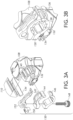
- FIG. 8 a perspective depiction of another embodiment of an adjustable clamping mechanism is shown.
- this additional embodiment includes similar environmental features (e.g., handlebar, throttle lever, etc.) that function in a similar manner with respect to the embodiment discussed above.
- the below disclosures will focus mainly on the differences between the separate embodiments.
- a throttle control device 200 includes a throttle lever 202 and a sensor (not shown) that is at least partially housed within a housing 204.
- the throttle control device 200 is an electronic throttle control; however, it is understood that the invention could also be used with a mechanical throttle control.
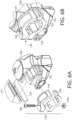
- the throttle lever 202 has a pivot portion 206 and a lever portion 208.
- the pivot portion 206 is pivotally fastened to the housing 204 by a screw or other mechanical fastener.
- the lever portion 208 extends laterally outwards from the pivot portion 206. The operator can grip a handlebar 210 and the throttle lever 202 with their hand and apply force to the throttle lever 202 to thereby pivot it towards or away from the handlebar 210.
- the throttle lever 202 rotates about a pivot axis, which coincides with a shaft of the screw.
- the pivot axis is perpendicular to an axis of the handlebar 210.
- the throttle lever 202 In an "idle" position of the throttle lever 202, the end of the throttle lever 202 is farthest away from the handlebar 210. In the “idle” position, the throttle lever 202 and the handlebar axis form an arcuate angle. When the throttle lever 202 is pivoted toward the handlebar 210, it is in the "drive” position where the angle between the throttle lever 202 and the handlebar axis is smaller than in the "idle” position. Other angular configurations between the throttle lever 202 and the handlebar 210 are also contemplated. The throttle lever 202 can be biased toward the "idle” position such that when no external force is applied to the throttle lever 202 it will pivot toward the "idle” position.
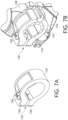
- the throttle control device 200 further includes a locking device that is used to attach it to the handlebar 210.
- the locking device comprises a first locking body 212 and a second locking body 214 that are attached to and held in place on the handlebar 210 by the interaction of a first set of integrated teeth 216 (disposed on the first locking body 212) and a second set of integrated teeth 218 (disposed on the second locking body 214) that are clamped together in a direction along the longitudinal axis of the handlebar 210.
- each of the first and second locking bodies 212, 214 comprises a generally cylindrical, hollow body with a central through-hole that is configured to be fit upon and receive the handlebar 210.
- each of the first and second locking bodies 212, 214 is formed of elongated teeth that are spaced periodically (at equal, non-equal, or random distances) around the radial perimeter of the locking body.
- the teeth are elongated in an axial direction of the locking body, and extend outwards from an end flange 213, 215.
- the teeth, and the troughs between them, of both the first and second locking bodies 212, 214 correspond to one another so that the teeth of one locking body interfit into the troughs of the other locking body, and vice-versa.
- At least one, and preferably a majority or all, of the elongated teeth of the first and second locking bodies 212, 214 have a tapered, wedge-shaped geometry.
- the elongated teeth tapers to a narrower width along the axial direction as they extend outwards from the end flange 213, 215 (i.e., the teeth are narrowest at the distal end, and widest at the proximal end adjacent the end flange 213, 215).
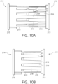
- first and second locking bodies 212, 214 are moved together along the axial direction (i.e., along their longitudinal lengths), as shown in FIG. 10B , the wedge-shaped teeth inter-engage to a greater and greater extent as the first and second locking bodies 212, 214 slide towards each other.
- the at least one, and preferably a majority or all, of the elongated teeth of the first and second locking bodies 212, 214 have a tapered, wedge-shaped geometry along a second axis, in particular, along the radial axis.
- the elongated teeth taper outwards to a relatively wider width in a radial direction, such that the teeth are relatively narrower towards the inner diameter and relatively wider towards the outer diameter.
- the first and second locking bodies 212, 214 are moved together along the axial direction (i.e., along their longitudinal lengths)
- the first and second sets of integrated teeth 216, 216 interengage against one another other along multiple axes.
- the wedge-shaped geometry of the teeth along the radial axis act upon each other as a cam to apply a clamping force to the handlebar 210 that securely retains the locking device, and ultimately the throttle control device 200, upon the handlebar 210.
- the first and second locking bodies 212, 214 can be secured to each other in various manners.
- the second locking body 214 includes a tooth having an upstanding boss 224 at a distal end thereof.
- the upstanding boss 224 projects radially outwards and is used to retain a screw or other mechanical fastener.
- the first locking body 212 includes a through-hole 226 that is aligned with the upstanding boss 224 in the axial direction and permits the screw to pass through the first locking body 212 and engage with the upstanding boss 224. This positively secures the locking device to the handlebar 210.
- any number of teeth in either of the first and/or second sets of integrated teeth 216, 218 may include upstanding bosses that are angularly spaced apart (e.g., 90°, 120°, 180°, etc.).
- the engagement between the screw and the upstanding boss 224 serves to secure the first and second locking bodies 212, 214 together, and by drawing the first and second locking bodies 212, 214 towards each other, also forces the first and second sets of integrated teeth 216, 218 to fully engage with each other, which causes the radial cam structure of the teeth to clamp the first and second locking bodies 212, 214 upon the handlebar 210.
- the first and second locking bodies 212, 214 can be secured to one another by additional means (e.g., a snap-fit/snap-lock structure, another clamping structure, adhesives, welding, etc.).
- a helical spring 220 is captured around the external perimeter of the first and second sets of integrated teeth 216, 218, and is captured between the end flanges 213, 215 of the first and second locking bodies 212, 214, respectively.
- the helical spring 220 biases the adjustment mechanism to the locked position when moving the position of the throttle control device 200, as will further be described below.
- the helical spring 220 can engage the end flange 213, 215 of the first and second locking bodies 212, 214, respectively, directly or indirectly through intermediary structure.
- one end of the helical spring 220 can rest against upstanding stop(s) that extend longitudinally from one of the end flanges.
- a washer 222 or the like can be interposed between the helical spring 220 and the upstanding stops to increase the surface area contact and/or to provide an operative surface to compress the helical spring 220 when adjusting the position of the throttle control device 200, as will be described.
- washers 222 can support both ends of the helical spring 220.
- the orientation or position of the throttle control device 200 is adjusted upon the handlebar 210 by the interaction of a cylindrical adjustment body 228 that slidingly telescopes relative to the locking device.
- the cylindrical adjustment body 228 may be formed integral with the housing 204.
- the cylindrical adjustment body 228 surrounds the locking device and includes a through-hole extending along the entire longitudinal axis that receives the locking device.
- the inner diameter of the cylindrical adjustment body 228 is larger than the outer diameter of the locking device such that an annular gap is formed therebetween.
- the helical spring 220 is located in the gap.
- An interior end wall of the cylindrical adjustment body 228 is in engagement with the helical spring 220 and/or the washer(s) 222 so that sliding movement of the cylindrical adjustment body 228 upon the handlebar 210 thereby compresses the helical spring 220.
- the end wall of the cylindrical adjustment body 228 further comprises at least one axial adjustment recess 230.
- a plurality of adjustment recesses 230 are angularly spaced apart along the perimeter of the interior side of the cylindrical adjustment body 228.
- the adjustment recesses 230 can be discretely spaced along about half of the cylindrical adjustment body 228 and can be periodically spaced apart (e.g., 15°, 25°, 30°, etc.) so that the adjustment angles are indexed at predetermined angles. It is to be understood that the number, spacing, and overall distance of the adjustment recesses 230 can correspond to the amount of overall angular adjustment of the throttle control device 200, and discrete adjustment intervals desired for the throttle control device 200 relative to the handlebar 210.
- the locking device includes at least one adjustment tooth 232 extending outwards from the end flange 215 of the second locking body 214.
- a plurality of adjustment teeth 232 are provided that match the relative size, shape, and positions of the adjustment recesses 230 to enable mating engagement thereof.
- the adjustment teeth 232 of the locking device are configured to tightly fit within the adjustment recesses 230 of the cylindrical adjustment body 228.
- the adjustable clamping mechanism includes only a single adjustment tooth 232 configured to be received in a single elongated, angular adjustment recess 230, the position of the throttle control device 200 can be infinitely.
- the adjustable clamping mechanism can include only a single adjustment tooth 232 and the cylindrical adjustment body 228 can include multiple angular adjustment recesses such that the throttle control device 200 can be detented as selected angular intervals to positively hold the throttle control device 200 in place.
- the adjustable clamping mechanism can include a plurality of adjustment teeth 232, as shown in FIG. 14 , the position of the throttle control device 200 can be detented at selected angular intervals to positively hold the throttle control device 200 in place until some force is applied to click into another detent position.
- the adjustable clamping mechanism can have a reverse configuration whereby the cylindrical adjustment body 228 includes the adjustment teeth 232 and the locking device includes the adjustment recesses 230, or even combinations thereof (e.g., both the cylindrical adjustment body 228 and the locking device include both adjustment teeth 232 and adjustment recesses 230).
- the at least one adjustment tooth 232 has a tapered profile to more easily align the with the adjustment recess 230; the at least one adjustment recess 230 can have a similar tapered profile.
- the tapered profile of the adjustment recesses 230 can be relatively wider at the open end to facilitate receiving and guiding of the adjustment teeth 232 therein.
- the at least one adjustment tooth 232 can have various other profiles (e.g., square, rectangular, etc.) and the at least one adjustment recess 230 can have a suitable corresponding profile. Any shape or configuration of the at least one adjustment tooth 232 and the at least one adjustment recess 230 is contemplated.
- At least one adjustment tooth 232 of the locking device is in engagement with one of the adjustment recesses 230 of the cylindrical adjustment body 228.
- the interaction between the at least one adjustment tooth 232 and the corresponding adjustment recess 230 of the cylindrical adjustment body 228 prevents further rotation of the throttle control device 200 about the handlebar 210.
- all of the adjustment teeth 232 are completely removed or disengaged from the adjustment recesses 230 so that the cylindrical adjustment body 228 can be rotated about the handlebar 210.
- the adjustment teeth 232 have an overall length that is less than the maximum telescopic movement distance of the cylindrical adjustment body 228 to thereby enable the adjustment teeth 232 to be completely removed from the adjustment recesses 230.
- the helical spring 220 biases the cylindrical adjustment body 228 towards the locked position whereby the adjustment teeth 232 are biased into engagement with the adjustment recesses 230.
- an operator applies a translational force to the cylindrical adjustment body 228 to slidingly telescope it relative to the locking device (i.e., along the longitudinal axis) and handlebar 210.
- the translational force is great enough to overcome the inward biasing force of the helical spring 220. This movement causes disengagement of the adjustment teeth 232 from the adjustment recesses 230.
- the cylindrical adjustment body 228 is now in the unlocked position and free to rotate relative to the handlebar 210.
- the operator while continuing to apply the translational force, then rotates the throttle control device 200 about the handlebar 210 to a new chosen angular orientation. Once the throttle control device 200 is rotated to the chosen orientation, the operator then stops applying the translational force. As such, the inward biasing force of the helical spring 220 forces the cylindrical adjustment body 228 to the locked position wherein the adjustment teeth 232 engage the adjustment recesses 230.
- the operator can intentionally misalign the adjustment teeth 232 and the adjustment recesses 230 so that the throttle control device 200 remains in the unlocked position even when the operator is no longer applying the translational force.
- further rotation of the throttle control device 200 would enable the helical spring 220 to re-engage the adjustment teeth 232 and the adjustment recesses 230.
- the device can be configured to defeat attempts to misalign the adjustment teeth 232 and the adjustment recesses 230 so that the cylindrical adjustment body 228 must be in the locked position when the operator releases the translational force.
- Such a configuration could be accomplished variously, such as by way of a modified adjustment tooth 232 and adjustment recess 230 design, and/or a keyed design that resists placement of the cylindrical adjustment body 228 in an intermediate position.
- the adjustable clamping mechanism can include a torsional spring that acts upon the cylindrical adjustment body 228 to rotationally force it away from an intermediate position and into the locked position (e.g., engagement of the adjustment teeth 232 and the adjustment recesses 230).
Landscapes
- Engineering & Computer Science (AREA)
- General Engineering & Computer Science (AREA)
- Mechanical Engineering (AREA)
- Chemical & Material Sciences (AREA)
- Combustion & Propulsion (AREA)
- Transportation (AREA)
- Physics & Mathematics (AREA)
- General Physics & Mathematics (AREA)
- Automation & Control Theory (AREA)
- Control Of Throttle Valves Provided In The Intake System Or In The Exhaust System (AREA)
- Steering Devices For Bicycles And Motorcycles (AREA)
- Clamps And Clips (AREA)
Claims (15)
- Eine Drosselsteuerungseinrichtung mit einem einstellbaren Klemmmechanismus für einen Lenker (102) eines Fahrzeugs, aufweisend:einen Drosselhebel (104), der einen einstellbaren gekrümmten Winkel in Bezug auf den Lenker (102) bildet und relativ dazu schwenkbar ist, wobei der Drosselhebel (104) zum Einstellen einer Motordrehzahl des Fahrzeugs vorgesehen ist; undeine Klemmvorrichtung (106), die die Drosselsteuerungseinrichtung (100) in einer gewünschten Winkelposition an dem Lenker (102) hält, die Klemmvorrichtung (106) aufweisend:einen Körper mit einem Hauptabschnitt (108) und einem Sekundärabschnitt (110), wobei der Hauptabschnitt (108) einen darin ausgebildeten Schlitz (116) aufweist, der zur Aufnahme des Lenkers (102) ausgebildet ist, wobei der Schlitz (116) eine erste Innenfläche (122) aufweist, die komplementär zu einem ersten Teil einer Umfangsfläche des Lenkers (102) ausgebildet ist, wobei der Sekundärabschnitt (110) in dem Schlitz (116) angeordnet und in Bezug auf den Hauptabschnitt (108) entfernbar ist, wobei der Sekundärabschnitt (110) eine zweite Innenfläche (128) aufweist, die komplementär zu einem zweiten Teil der Umfangsfläche des Lenkers (102) ausgebildet ist; dadurch gekennzeichnet, dassein Klemmelement (130) zum Ausüben einer Klemmkraft auf den Hauptabschnitt (108) und den Sekundärabschnitt (110) des Körpers vorgesehen ist, wobei in einer Eingriffsposition des Klemmelements (130) das Klemmelement (130) eine Klemmkraft zwischen dem Hauptabschnitt (108) und dem Sekundärabschnitt (110) und auf den Lenker (102) bereitstellt, die ausreicht, um dadurch den Drosselhebel (104) während des Betriebs des Fahrzeugs in einer vorbestimmten Winkelausrichtung auf dem Lenker (102) zu halten, und wobei in einer Außereingriffsposition des Klemmelements (130) das Klemmelement (130) die Klemmkraft nicht bereitstellt, um eine Drehung des Drosselhebels (104) um eine Längsachse des Lenkers (102) zu ermöglichen.
- Drosselsteuerungseinrichtung mit dem einstellbaren Klemmmechanismus nach Anspruch 1, wobei der Körper ferner ein Verlängerungselement aufweist, das in Bezug auf den Lenker (102) in axialer Richtung von dem Körper weg vorsteht, wobei das Klemmelement (130) das Verlängerungselement umfangsmäßig umgibt und in Bezug auf den Körper abnehmbar daran angeordnet ist.
- Drosselsteuerungseinrichtung mit dem einstellbaren Klemmmechanismus nach Anspruch 2, wobei das Verlängerungselement ein erstes und ein zweites Segment (132, 134) aufweist, wobei sich das erste Segment (132) direkt von dem Hauptabschnitt (108) des Körpers nach außen erstreckt und das zweite Segment (134) sich direkt von dem Sekundärabschnitt (110) des Körpers nach außen erstreckt.
- Drosselsteuerungseinrichtung mit dem einstellbaren Klemmmechanismus nach Anspruch 3, wobei das erste Segment (132) des Verlängerungselements eine erste Vielzahl von Zähnen (140) aufweist, die auf einer äußeren Umfangsfläche desselben ausgebildet sind.
- Drosselsteuerungseinrichtung mit dem einstellbaren Klemmmechanismus nach Anspruch 4, wobei das Klemmelement (130) eine zweite Vielzahl von Zähnen (142) aufweist, die auf einer inneren Umfangsfläche desselben ausgebildet sind, wobei die zweite Vielzahl von Zähnen (142) zu der ersten Vielzahl von Zähnen (140) korrespondiert.
- Drosselsteuerungseinrichtung mit dem einstellbaren Klemmmechanismus nach Anspruch 5, wobei das Klemmelement (130) eine Bandklemme ist, die ferner ein erstes Element (144) aufweist, das von einem zweiten Element (146) getrennt und verschieden ist, wobei das erste und das zweite Element (144, 146) nur an einer einzigen Seite aneinander befestigt sind.
- Drosselsteuerungseinrichtung mit dem einstellbaren Klemmmechanismus nach Anspruch 6, wobei das Klemmelement (130) ferner einen Nockenhebel (152) aufweist, der benachbart zu dem ersten Element (144) angeordnet ist, wobei der Nockenhebel (152) eine Nockenfläche (160) aufweist, die dazu ausgebildet ist, mit einer Eingriffsfläche (162) an dem ersten Element (144) derart zusammenzuwirken, dass:in der Eingriffsposition des Klemmelements (130) die Nockenfläche (160) mit der Eingriffsfläche (162) zusammenwirkt, um die Klemmkraft zu erzeugen, undin der Außereingriffsposition des Klemmelements (130) die Nockenfläche (160) nicht mit der Eingriffsfläche (162) zusammenwirkt und somit die Klemmkraft nicht erzeugt.
- Drosselsteuerungseinrichtung mit dem einstellbaren Klemmmechanismus nach Anspruch 7, wobei der Hauptabschnitt (108) des Körpers ferner ein elastisches Armelement (136) aufweist, das sich in Bezug auf den Lenker (102) in axialer Richtung nach außen erstreckt, wobei das elastische Armelement (136) an seinem distalen Ende ein Sicherungselement (138) aufweist und sich das Sicherungselement (138) in einer radialen Richtung erstreckt, sodass das Sicherungselement (138) in einer Installationsposition des Klemmelements (130) an einer Außenseite des Klemmelements (130) anliegt.
- Drosselsteuerungseinrichtung mit dem einstellbaren Klemmmechanismus nach Anspruch 6, wobei das erste und das zweite Element (144, 146) durch eine Schrauben- und Mutter-Anordnung aneinander befestigt sind.
- Drosselsteuerungseinrichtung mit dem einstellbaren Klemmmechanismus nach Anspruch 4, wobei das Klemmelement (130) eine Bandklemme ist, die einen monolithischen elastischen Klemmkörper (154) mit einem ersten Klemmvorsprung (156) umfasst, der neben einem zweiten Klemmvorsprung (158) angeordnet ist.
- Drosselsteuerungseinrichtung mit dem einstellbaren Klemmmechanismus nach Anspruch 10, wobei das Klemmelement (130) ferner einen Nockenhebel (152) aufweist, der benachbart zu dem ersten Klemmvorsprung (156) angeordnet ist, wobei der Nockenhebel (152) eine Nockenfläche (160) aufweist, die dazu ausgebildet ist, mit einer Eingriffsfläche (162) an dem elastischen Klemmkörper (154) derart zusammenzuwirken, dass:in der Eingriffsposition des Klemmelements (130) die Nockenfläche (160) mit der Eingriffsfläche (162) zusammenwirkt, um die Klemmkraft über den gesamten elastischen Klemmkörper (154) zu erzeugen, undin der Außereingriffsposition des Klemmelements (130) die Nockenfläche (160) nicht mit der Eingriffsfläche (162) zusammenwirkt und somit die Klemmkraft nicht erzeugt.
- Drosselsteuerungseinrichtung mit dem einstellbaren Klemmmechanismus nach Anspruch 11, wobei der Hauptabschnitt (108) des Körpers ferner ein elastisches Armelement (136) aufweist, das sich in Bezug auf den Lenker (102) in axialer Richtung nach außen erstreckt, wobei das elastische Armelement (136) an seinem distalen Ende ein Sicherungselement (138) aufweist, wobei sich das Sicherungselement (138) in einer radialen Richtung erstreckt, sodass das Sicherungselement (138) in einer Installationsposition des Klemmelements (130) an einer Außenseite des Klemmelements (130) anliegt.
- Drosselsteuerungseinrichtung mit dem einstellbaren Klemmmechanismus nach Anspruch 10, wobei der erste und zweite Klemmvorsprung (156, 158) durch eine Schrauben- und Mutter-Anordnung aneinander befestigt sind.
- Drosselsteuerungseinrichtung mit dem einstellbaren Klemmmechanismus nach Anspruch 1, wobei der Sekundärabschnitt (110) des Körpers einen Sicherungsvorsprung (124) aufweist und der Hauptabschnitt (108) des Körpers eine Öffnung (126) aufweist, die zu einer Form des Sicherungsvorsprungs (124) korrespondiert, sodass der Sicherungsvorsprung (124) gleitend in der Öffnung (126) aufgenommen ist, wenn der Sekundärabschnitt (110) in dem Hauptabschnitt (108) angeordnet ist.
- Drosselsteuerungseinrichtung mit dem einstellbaren Klemmmechanismus nach Anspruch 1, wobei der Drosselhebel (104) beweglich an dem Hauptabschnitt (108) des Körpers befestigt ist oder wobei der Drosselhebel (104) an einer Oberseite (113) und einer Unterseite (115) des Hauptabschnitts (108) schwenkbar an dem Körper befestigt ist.
Applications Claiming Priority (2)
| Application Number | Priority Date | Filing Date | Title |
|---|---|---|---|
| US201762536252P | 2017-07-24 | 2017-07-24 | |
| PCT/US2018/043373 WO2019023162A1 (en) | 2017-07-24 | 2018-07-24 | ADJUSTABLE CLAMPING MECHANISM FOR GAS CONTROL |
Publications (4)
| Publication Number | Publication Date |
|---|---|
| EP3658784A1 EP3658784A1 (de) | 2020-06-03 |
| EP3658784A4 EP3658784A4 (de) | 2021-05-05 |
| EP3658784C0 EP3658784C0 (de) | 2024-05-01 |
| EP3658784B1 true EP3658784B1 (de) | 2024-05-01 |
Family
ID=65018665
Family Applications (1)
| Application Number | Title | Priority Date | Filing Date |
|---|---|---|---|
| EP18838437.4A Active EP3658784B1 (de) | 2017-07-24 | 2018-07-24 | Einstellbarer klemmmechanismus für eine drosselsteuerung |
Country Status (6)
| Country | Link |
|---|---|
| US (1) | US10372151B2 (de) |
| EP (1) | EP3658784B1 (de) |
| JP (1) | JP7026770B2 (de) |
| CN (1) | CN110914556B (de) |
| ES (1) | ES2984410T3 (de) |
| WO (1) | WO2019023162A1 (de) |
Families Citing this family (2)
| Publication number | Priority date | Publication date | Assignee | Title |
|---|---|---|---|---|
| TWI641531B (zh) * | 2017-05-31 | 2018-11-21 | 彥豪金屬工業股份有限公司 | 自行車後變速器 |
| WO2023046281A1 (en) * | 2021-09-22 | 2023-03-30 | Worxsafe Ab | A mesh panel holder |
Family Cites Families (29)
| Publication number | Priority date | Publication date | Assignee | Title |
|---|---|---|---|---|
| US3948361A (en) * | 1974-07-24 | 1976-04-06 | Arctic Enterprises, Inc. | Parking brake mechanism |
| US4213513A (en) * | 1978-06-26 | 1980-07-22 | Mcgill Manufacturing Company, Inc. | Ignition control system with safety switches |
| IT8422920U1 (it) * | 1984-08-28 | 1986-02-28 | Carnielli & C Teodoro Spa | Dispositivo meccanico, applicabile su biciclette in genere, per il bloccaggio rapido di parti montate su tubo tondo metallico. |
| JPH01155725U (de) * | 1988-04-20 | 1989-10-26 | ||
| US4899610A (en) | 1988-09-28 | 1990-02-13 | Bombardier Inc. | Throttle lever |
| US5404769A (en) * | 1994-05-18 | 1995-04-11 | Kao; Cheng-Hsien | Adjustable bicycle handlebar stem |
| JP2002256904A (ja) | 2001-02-28 | 2002-09-11 | Mikuni Corp | アクセル操作装置 |
| JP3648475B2 (ja) | 2001-11-19 | 2005-05-18 | タカノ株式会社 | クランプ装置及びクランプ装置を備えたテーブル及び連結装置 |
| JP2003252273A (ja) | 2002-02-26 | 2003-09-10 | Yamaha Motor Co Ltd | スロットル開度検出装置 |
| JP4112876B2 (ja) | 2002-02-26 | 2008-07-02 | ヤマハ発動機株式会社 | スロットル開度検出装置 |
| JP4488985B2 (ja) * | 2005-09-05 | 2010-06-23 | 三洋電機株式会社 | 自転車用付属部品取付装置 |
| US7735470B2 (en) | 2007-01-10 | 2010-06-15 | Delphi Technologies, Inc. | Throttle control cartridge with double cam to force idle position |
| US20090078076A1 (en) * | 2007-09-24 | 2009-03-26 | Chao-Hu Chen | Adjustable handlebar stem assembly |
| JP4846695B2 (ja) * | 2007-11-22 | 2011-12-28 | スターテング工業株式会社 | セルスタートスイッチ付きスロットル調整機構 |
| ITMI20080632A1 (it) | 2008-04-10 | 2009-10-11 | Domino Spa | Dispositivo di comando del gas elettronico perfezionato per motocicli, motociclette, motoslitte e similari veicoli |
| CN102083682B (zh) | 2008-04-30 | 2013-11-06 | 庞巴迪动力产品公司 | 车把上具有变速杆的车辆 |
| US8491348B2 (en) | 2008-06-30 | 2013-07-23 | Bombardier Recreational Products Inc. | Lever position sensor |
| US20100111595A1 (en) | 2008-11-04 | 2010-05-06 | Chang Hui Lin | Quick release device for bicycle |
| US20100182017A1 (en) | 2009-01-21 | 2010-07-22 | Honeywell International Inc. | Drive by wire non-contact capacitive throttle control apparatus and method of forming the same |
| JP5448148B2 (ja) | 2009-06-05 | 2014-03-19 | 朝日電装株式会社 | スロットルグリップ装置 |
| CN201571383U (zh) | 2009-11-05 | 2010-09-08 | 浙江中马园林机器有限公司 | 拆装式自动控制高把油锯 |
| RU2646029C2 (ru) * | 2012-06-29 | 2018-02-28 | Бомбардье Рекриэйшенел Продактс Инк. | Модуль управления дросселем и транспортное средство |
| RU2660235C2 (ru) | 2013-01-30 | 2018-07-05 | Бомбардье Рекриэйшенел Продактс Инк. | Способ (варианты ) эксплуатации транспортного средства |
| US9174697B2 (en) * | 2013-10-07 | 2015-11-03 | Shimano Inc. | Bicycle operating device |
| US9533571B1 (en) * | 2014-01-20 | 2017-01-03 | Robert Istvan Urmosi | Finger-operated lever device to be installed on a vehicle handlebar for actuating a cable of a vehicle |
| JP6675737B2 (ja) | 2015-07-01 | 2020-04-01 | 株式会社dak | 緊急時制御装置 |
| US10137957B2 (en) * | 2015-08-06 | 2018-11-27 | Shimano Inc. | Bicycle operating device |
| WO2017046731A1 (en) * | 2015-09-15 | 2017-03-23 | Lurco Trading 268 (Pty) Ltd | A weight retention clamp |
| CN207246170U (zh) * | 2017-10-11 | 2018-04-17 | 深圳市洲明科技股份有限公司 | 拼装连接锁和led显示屏 |
-
2018
- 2018-07-24 EP EP18838437.4A patent/EP3658784B1/de active Active
- 2018-07-24 CN CN201880045089.XA patent/CN110914556B/zh active Active
- 2018-07-24 ES ES18838437T patent/ES2984410T3/es active Active
- 2018-07-24 JP JP2020502564A patent/JP7026770B2/ja active Active
- 2018-07-24 WO PCT/US2018/043373 patent/WO2019023162A1/en not_active Ceased
- 2018-07-24 US US16/043,406 patent/US10372151B2/en active Active
Also Published As
| Publication number | Publication date |
|---|---|
| CN110914556A (zh) | 2020-03-24 |
| US10372151B2 (en) | 2019-08-06 |
| JP7026770B2 (ja) | 2022-02-28 |
| ES2984410T3 (es) | 2024-10-29 |
| CN110914556B (zh) | 2021-09-21 |
| JP2020528511A (ja) | 2020-09-24 |
| US20190025871A1 (en) | 2019-01-24 |
| EP3658784A1 (de) | 2020-06-03 |
| EP3658784C0 (de) | 2024-05-01 |
| WO2019023162A1 (en) | 2019-01-31 |
| EP3658784A4 (de) | 2021-05-05 |
Similar Documents
| Publication | Publication Date | Title |
|---|---|---|
| US11046411B2 (en) | Tiller assembly for a marine outboard engine | |
| US5301567A (en) | Low pivot tilt steering column clamping mechanism | |
| EP3658784B1 (de) | Einstellbarer klemmmechanismus für eine drosselsteuerung | |
| US4875386A (en) | Handlegrip cruise assist device | |
| EP1070652A2 (de) | Klemmeinrichtung für eine Lenksäule | |
| US6167777B1 (en) | Tiltable steering column lock mechanism | |
| US20130241271A1 (en) | Bicycle axle assembly | |
| US20150135542A1 (en) | Feedback system for bar clamping | |
| US6558240B2 (en) | Honing tool | |
| US6640661B2 (en) | Tilt steering wheel | |
| US20050056671A1 (en) | Motorcycle with accessory | |
| JP3140677U (ja) | 伸縮装置及び傘取付け具 | |
| US7806023B2 (en) | Thumb grip extension device for motorcycle throttle screw | |
| US20030230023A1 (en) | Rod rest | |
| US20170282804A1 (en) | View angle adjustment mechanism in view device | |
| EP3574737B1 (de) | Einstellsystem für eine lenkeinheit | |
| US6959622B2 (en) | Rotary tilt locking mechanism | |
| JP2007153088A (ja) | ステアリング装置 | |
| GB2352285A (en) | Clamping device for a steering column | |
| JPS6036512Y2 (ja) | ステアリングの軸方向調整装置 | |
| JP2015085505A (ja) | トルクレンチ | |
| JPS6325265Y2 (de) | ||
| JP2535348Y2 (ja) | ハンドル取付構造 | |
| JP3020245U (ja) | 傾斜調整可能な自転車ハンドル | |
| JP6387298B2 (ja) | ステアリング装置 |
Legal Events
| Date | Code | Title | Description |
|---|---|---|---|
| STAA | Information on the status of an ep patent application or granted ep patent |
Free format text: STATUS: THE INTERNATIONAL PUBLICATION HAS BEEN MADE |
|
| PUAI | Public reference made under article 153(3) epc to a published international application that has entered the european phase |
Free format text: ORIGINAL CODE: 0009012 |
|
| STAA | Information on the status of an ep patent application or granted ep patent |
Free format text: STATUS: REQUEST FOR EXAMINATION WAS MADE |
|
| 17P | Request for examination filed |
Effective date: 20200224 |
|
| AK | Designated contracting states |
Kind code of ref document: A1 Designated state(s): AL AT BE BG CH CY CZ DE DK EE ES FI FR GB GR HR HU IE IS IT LI LT LU LV MC MK MT NL NO PL PT RO RS SE SI SK SM TR |
|
| AX | Request for extension of the european patent |
Extension state: BA ME |
|
| DAV | Request for validation of the european patent (deleted) | ||
| DAX | Request for extension of the european patent (deleted) | ||
| A4 | Supplementary search report drawn up and despatched |
Effective date: 20210401 |
|
| RIC1 | Information provided on ipc code assigned before grant |
Ipc: F16B 2/06 20060101AFI20210326BHEP Ipc: G05G 1/08 20060101ALI20210326BHEP Ipc: G05G 5/22 20060101ALI20210326BHEP Ipc: B60K 26/02 20060101ALI20210326BHEP |
|
| STAA | Information on the status of an ep patent application or granted ep patent |
Free format text: STATUS: EXAMINATION IS IN PROGRESS |
|
| 17Q | First examination report despatched |
Effective date: 20220210 |
|
| GRAP | Despatch of communication of intention to grant a patent |
Free format text: ORIGINAL CODE: EPIDOSNIGR1 |
|
| STAA | Information on the status of an ep patent application or granted ep patent |
Free format text: STATUS: GRANT OF PATENT IS INTENDED |
|
| INTG | Intention to grant announced |
Effective date: 20231218 |
|
| GRAS | Grant fee paid |
Free format text: ORIGINAL CODE: EPIDOSNIGR3 |
|
| GRAA | (expected) grant |
Free format text: ORIGINAL CODE: 0009210 |
|
| STAA | Information on the status of an ep patent application or granted ep patent |
Free format text: STATUS: THE PATENT HAS BEEN GRANTED |
|
| AK | Designated contracting states |
Kind code of ref document: B1 Designated state(s): AL AT BE BG CH CY CZ DE DK EE ES FI FR GB GR HR HU IE IS IT LI LT LU LV MC MK MT NL NO PL PT RO RS SE SI SK SM TR |
|
| REG | Reference to a national code |
Ref country code: GB Ref legal event code: FG4D |
|
| REG | Reference to a national code |
Ref country code: CH Ref legal event code: EP |
|
| REG | Reference to a national code |
Ref country code: IE Ref legal event code: FG4D |
|
| REG | Reference to a national code |
Ref country code: DE Ref legal event code: R096 Ref document number: 602018069050 Country of ref document: DE |
|
| U01 | Request for unitary effect filed |
Effective date: 20240528 |
|
| U07 | Unitary effect registered |
Designated state(s): AT BE BG DE DK EE FI FR IT LT LU LV MT NL PT SE SI Effective date: 20240606 |
|
| U20 | Renewal fee for the european patent with unitary effect paid |
Year of fee payment: 7 Effective date: 20240604 |
|
| PG25 | Lapsed in a contracting state [announced via postgrant information from national office to epo] |
Ref country code: IS Free format text: LAPSE BECAUSE OF FAILURE TO SUBMIT A TRANSLATION OF THE DESCRIPTION OR TO PAY THE FEE WITHIN THE PRESCRIBED TIME-LIMIT Effective date: 20240901 |
|
| PG25 | Lapsed in a contracting state [announced via postgrant information from national office to epo] |
Ref country code: HR Free format text: LAPSE BECAUSE OF FAILURE TO SUBMIT A TRANSLATION OF THE DESCRIPTION OR TO PAY THE FEE WITHIN THE PRESCRIBED TIME-LIMIT Effective date: 20240501 |
|
| PG25 | Lapsed in a contracting state [announced via postgrant information from national office to epo] |
Ref country code: GR Free format text: LAPSE BECAUSE OF FAILURE TO SUBMIT A TRANSLATION OF THE DESCRIPTION OR TO PAY THE FEE WITHIN THE PRESCRIBED TIME-LIMIT Effective date: 20240802 |
|
| PG25 | Lapsed in a contracting state [announced via postgrant information from national office to epo] |
Ref country code: PL Free format text: LAPSE BECAUSE OF FAILURE TO SUBMIT A TRANSLATION OF THE DESCRIPTION OR TO PAY THE FEE WITHIN THE PRESCRIBED TIME-LIMIT Effective date: 20240501 |
|
| REG | Reference to a national code |
Ref country code: ES Ref legal event code: FG2A Ref document number: 2984410 Country of ref document: ES Kind code of ref document: T3 Effective date: 20241029 |
|
| PG25 | Lapsed in a contracting state [announced via postgrant information from national office to epo] |
Ref country code: PL Free format text: LAPSE BECAUSE OF FAILURE TO SUBMIT A TRANSLATION OF THE DESCRIPTION OR TO PAY THE FEE WITHIN THE PRESCRIBED TIME-LIMIT Effective date: 20240501 Ref country code: NO Free format text: LAPSE BECAUSE OF FAILURE TO SUBMIT A TRANSLATION OF THE DESCRIPTION OR TO PAY THE FEE WITHIN THE PRESCRIBED TIME-LIMIT Effective date: 20240801 Ref country code: IS Free format text: LAPSE BECAUSE OF FAILURE TO SUBMIT A TRANSLATION OF THE DESCRIPTION OR TO PAY THE FEE WITHIN THE PRESCRIBED TIME-LIMIT Effective date: 20240901 Ref country code: HR Free format text: LAPSE BECAUSE OF FAILURE TO SUBMIT A TRANSLATION OF THE DESCRIPTION OR TO PAY THE FEE WITHIN THE PRESCRIBED TIME-LIMIT Effective date: 20240501 Ref country code: GR Free format text: LAPSE BECAUSE OF FAILURE TO SUBMIT A TRANSLATION OF THE DESCRIPTION OR TO PAY THE FEE WITHIN THE PRESCRIBED TIME-LIMIT Effective date: 20240802 Ref country code: RS Free format text: LAPSE BECAUSE OF FAILURE TO SUBMIT A TRANSLATION OF THE DESCRIPTION OR TO PAY THE FEE WITHIN THE PRESCRIBED TIME-LIMIT Effective date: 20240801 |
|
| PG25 | Lapsed in a contracting state [announced via postgrant information from national office to epo] |
Ref country code: CZ Free format text: LAPSE BECAUSE OF FAILURE TO SUBMIT A TRANSLATION OF THE DESCRIPTION OR TO PAY THE FEE WITHIN THE PRESCRIBED TIME-LIMIT Effective date: 20240501 |
|
| PG25 | Lapsed in a contracting state [announced via postgrant information from national office to epo] |
Ref country code: SK Free format text: LAPSE BECAUSE OF FAILURE TO SUBMIT A TRANSLATION OF THE DESCRIPTION OR TO PAY THE FEE WITHIN THE PRESCRIBED TIME-LIMIT Effective date: 20240501 Ref country code: RO Free format text: LAPSE BECAUSE OF FAILURE TO SUBMIT A TRANSLATION OF THE DESCRIPTION OR TO PAY THE FEE WITHIN THE PRESCRIBED TIME-LIMIT Effective date: 20240501 |
|
| PG25 | Lapsed in a contracting state [announced via postgrant information from national office to epo] |
Ref country code: SM Free format text: LAPSE BECAUSE OF FAILURE TO SUBMIT A TRANSLATION OF THE DESCRIPTION OR TO PAY THE FEE WITHIN THE PRESCRIBED TIME-LIMIT Effective date: 20240501 |
|
| PG25 | Lapsed in a contracting state [announced via postgrant information from national office to epo] |
Ref country code: SM Free format text: LAPSE BECAUSE OF FAILURE TO SUBMIT A TRANSLATION OF THE DESCRIPTION OR TO PAY THE FEE WITHIN THE PRESCRIBED TIME-LIMIT Effective date: 20240501 Ref country code: SK Free format text: LAPSE BECAUSE OF FAILURE TO SUBMIT A TRANSLATION OF THE DESCRIPTION OR TO PAY THE FEE WITHIN THE PRESCRIBED TIME-LIMIT Effective date: 20240501 Ref country code: RO Free format text: LAPSE BECAUSE OF FAILURE TO SUBMIT A TRANSLATION OF THE DESCRIPTION OR TO PAY THE FEE WITHIN THE PRESCRIBED TIME-LIMIT Effective date: 20240501 Ref country code: CZ Free format text: LAPSE BECAUSE OF FAILURE TO SUBMIT A TRANSLATION OF THE DESCRIPTION OR TO PAY THE FEE WITHIN THE PRESCRIBED TIME-LIMIT Effective date: 20240501 |
|
| REG | Reference to a national code |
Ref country code: DE Ref legal event code: R097 Ref document number: 602018069050 Country of ref document: DE |
|
| PG25 | Lapsed in a contracting state [announced via postgrant information from national office to epo] |
Ref country code: MC Free format text: LAPSE BECAUSE OF FAILURE TO SUBMIT A TRANSLATION OF THE DESCRIPTION OR TO PAY THE FEE WITHIN THE PRESCRIBED TIME-LIMIT Effective date: 20240501 |
|
| REG | Reference to a national code |
Ref country code: CH Ref legal event code: PL |
|
| PLBE | No opposition filed within time limit |
Free format text: ORIGINAL CODE: 0009261 |
|
| STAA | Information on the status of an ep patent application or granted ep patent |
Free format text: STATUS: NO OPPOSITION FILED WITHIN TIME LIMIT |
|
| 26N | No opposition filed |
Effective date: 20250204 |
|
| PG25 | Lapsed in a contracting state [announced via postgrant information from national office to epo] |
Ref country code: CH Free format text: LAPSE BECAUSE OF NON-PAYMENT OF DUE FEES Effective date: 20240731 |
|
| PGFP | Annual fee paid to national office [announced via postgrant information from national office to epo] |
Ref country code: GB Payment date: 20250619 Year of fee payment: 8 |
|
| PGFP | Annual fee paid to national office [announced via postgrant information from national office to epo] |
Ref country code: TR Payment date: 20250627 Year of fee payment: 8 |
|
| PG25 | Lapsed in a contracting state [announced via postgrant information from national office to epo] |
Ref country code: IE Free format text: LAPSE BECAUSE OF NON-PAYMENT OF DUE FEES Effective date: 20240724 |
|
| U20 | Renewal fee for the european patent with unitary effect paid |
Year of fee payment: 8 Effective date: 20250620 |
|
| PGFP | Annual fee paid to national office [announced via postgrant information from national office to epo] |
Ref country code: ES Payment date: 20250801 Year of fee payment: 8 |
|
| PG25 | Lapsed in a contracting state [announced via postgrant information from national office to epo] |
Ref country code: CY Free format text: LAPSE BECAUSE OF FAILURE TO SUBMIT A TRANSLATION OF THE DESCRIPTION OR TO PAY THE FEE WITHIN THE PRESCRIBED TIME-LIMIT; INVALID AB INITIO Effective date: 20180724 |
|
| PG25 | Lapsed in a contracting state [announced via postgrant information from national office to epo] |
Ref country code: HU Free format text: LAPSE BECAUSE OF FAILURE TO SUBMIT A TRANSLATION OF THE DESCRIPTION OR TO PAY THE FEE WITHIN THE PRESCRIBED TIME-LIMIT; INVALID AB INITIO Effective date: 20180724 |