EP3658698B1 - Verfahren zur herstellung einer einphasigen schicht aus intermetallischen verbindungen - Google Patents
Verfahren zur herstellung einer einphasigen schicht aus intermetallischen verbindungen Download PDFInfo
- Publication number
- EP3658698B1 EP3658698B1 EP18750326.3A EP18750326A EP3658698B1 EP 3658698 B1 EP3658698 B1 EP 3658698B1 EP 18750326 A EP18750326 A EP 18750326A EP 3658698 B1 EP3658698 B1 EP 3658698B1
- Authority
- EP
- European Patent Office
- Prior art keywords
- substrate
- intermetallic
- phase
- layer
- intermetallic compound
- Prior art date
- Legal status (The legal status is an assumption and is not a legal conclusion. Google has not performed a legal analysis and makes no representation as to the accuracy of the status listed.)
- Active
Links
Images
Classifications
-
- C—CHEMISTRY; METALLURGY
- C23—COATING METALLIC MATERIAL; COATING MATERIAL WITH METALLIC MATERIAL; CHEMICAL SURFACE TREATMENT; DIFFUSION TREATMENT OF METALLIC MATERIAL; COATING BY VACUUM EVAPORATION, BY SPUTTERING, BY ION IMPLANTATION OR BY CHEMICAL VAPOUR DEPOSITION, IN GENERAL; INHIBITING CORROSION OF METALLIC MATERIAL OR INCRUSTATION IN GENERAL
- C23C—COATING METALLIC MATERIAL; COATING MATERIAL WITH METALLIC MATERIAL; SURFACE TREATMENT OF METALLIC MATERIAL BY DIFFUSION INTO THE SURFACE, BY CHEMICAL CONVERSION OR SUBSTITUTION; COATING BY VACUUM EVAPORATION, BY SPUTTERING, BY ION IMPLANTATION OR BY CHEMICAL VAPOUR DEPOSITION, IN GENERAL
- C23C14/00—Coating by vacuum evaporation, by sputtering or by ion implantation of the coating forming material
- C23C14/22—Coating by vacuum evaporation, by sputtering or by ion implantation of the coating forming material characterised by the process of coating
- C23C14/34—Sputtering
- C23C14/35—Sputtering by application of a magnetic field, e.g. magnetron sputtering
-
- C—CHEMISTRY; METALLURGY
- C23—COATING METALLIC MATERIAL; COATING MATERIAL WITH METALLIC MATERIAL; CHEMICAL SURFACE TREATMENT; DIFFUSION TREATMENT OF METALLIC MATERIAL; COATING BY VACUUM EVAPORATION, BY SPUTTERING, BY ION IMPLANTATION OR BY CHEMICAL VAPOUR DEPOSITION, IN GENERAL; INHIBITING CORROSION OF METALLIC MATERIAL OR INCRUSTATION IN GENERAL
- C23C—COATING METALLIC MATERIAL; COATING MATERIAL WITH METALLIC MATERIAL; SURFACE TREATMENT OF METALLIC MATERIAL BY DIFFUSION INTO THE SURFACE, BY CHEMICAL CONVERSION OR SUBSTITUTION; COATING BY VACUUM EVAPORATION, BY SPUTTERING, BY ION IMPLANTATION OR BY CHEMICAL VAPOUR DEPOSITION, IN GENERAL
- C23C14/00—Coating by vacuum evaporation, by sputtering or by ion implantation of the coating forming material
- C23C14/06—Coating by vacuum evaporation, by sputtering or by ion implantation of the coating forming material characterised by the coating material
- C23C14/14—Metallic material, boron or silicon
- C23C14/16—Metallic material, boron or silicon on metallic substrates or on substrates of boron or silicon
-
- C—CHEMISTRY; METALLURGY
- C23—COATING METALLIC MATERIAL; COATING MATERIAL WITH METALLIC MATERIAL; CHEMICAL SURFACE TREATMENT; DIFFUSION TREATMENT OF METALLIC MATERIAL; COATING BY VACUUM EVAPORATION, BY SPUTTERING, BY ION IMPLANTATION OR BY CHEMICAL VAPOUR DEPOSITION, IN GENERAL; INHIBITING CORROSION OF METALLIC MATERIAL OR INCRUSTATION IN GENERAL
- C23C—COATING METALLIC MATERIAL; COATING MATERIAL WITH METALLIC MATERIAL; SURFACE TREATMENT OF METALLIC MATERIAL BY DIFFUSION INTO THE SURFACE, BY CHEMICAL CONVERSION OR SUBSTITUTION; COATING BY VACUUM EVAPORATION, BY SPUTTERING, BY ION IMPLANTATION OR BY CHEMICAL VAPOUR DEPOSITION, IN GENERAL
- C23C14/00—Coating by vacuum evaporation, by sputtering or by ion implantation of the coating forming material
- C23C14/22—Coating by vacuum evaporation, by sputtering or by ion implantation of the coating forming material characterised by the process of coating
- C23C14/34—Sputtering
- C23C14/3407—Cathode assembly for sputtering apparatus, e.g. Target
- C23C14/3414—Metallurgical or chemical aspects of target preparation, e.g. casting, powder metallurgy
-
- H—ELECTRICITY
- H01—ELECTRIC ELEMENTS
- H01J—ELECTRIC DISCHARGE TUBES OR DISCHARGE LAMPS
- H01J37/00—Discharge tubes with provision for introducing objects or material to be exposed to the discharge, e.g. for the purpose of examination or processing thereof
- H01J37/32—Gas-filled discharge tubes
- H01J37/34—Gas-filled discharge tubes operating with cathodic sputtering
- H01J37/3411—Constructional aspects of the reactor
- H01J37/3414—Targets
- H01J37/3426—Material
-
- B—PERFORMING OPERATIONS; TRANSPORTING
- B22—CASTING; POWDER METALLURGY
- B22F—WORKING METALLIC POWDER; MANUFACTURE OF ARTICLES FROM METALLIC POWDER; MAKING METALLIC POWDER; APPARATUS OR DEVICES SPECIALLY ADAPTED FOR METALLIC POWDER
- B22F3/00—Manufacture of workpieces or articles from metallic powder characterised by the manner of compacting or sintering; Apparatus specially adapted therefor ; Presses and furnaces
- B22F3/10—Sintering only
- B22F3/105—Sintering only by using electric current other than for infrared radiant energy, laser radiation or plasma ; by ultrasonic bonding
- B22F2003/1051—Sintering only by using electric current other than for infrared radiant energy, laser radiation or plasma ; by ultrasonic bonding by electric discharge
-
- B—PERFORMING OPERATIONS; TRANSPORTING
- B22—CASTING; POWDER METALLURGY
- B22F—WORKING METALLIC POWDER; MANUFACTURE OF ARTICLES FROM METALLIC POWDER; MAKING METALLIC POWDER; APPARATUS OR DEVICES SPECIALLY ADAPTED FOR METALLIC POWDER
- B22F3/00—Manufacture of workpieces or articles from metallic powder characterised by the manner of compacting or sintering; Apparatus specially adapted therefor ; Presses and furnaces
- B22F3/24—After-treatment of workpieces or articles
- B22F2003/247—Removing material: carving, cleaning, grinding, hobbing, honing, lapping, polishing, milling, shaving, skiving, turning the surface
-
- B—PERFORMING OPERATIONS; TRANSPORTING
- B22—CASTING; POWDER METALLURGY
- B22F—WORKING METALLIC POWDER; MANUFACTURE OF ARTICLES FROM METALLIC POWDER; MAKING METALLIC POWDER; APPARATUS OR DEVICES SPECIALLY ADAPTED FOR METALLIC POWDER
- B22F2202/00—Treatment under specific physical conditions
- B22F2202/13—Use of plasma
-
- B—PERFORMING OPERATIONS; TRANSPORTING
- B22—CASTING; POWDER METALLURGY
- B22F—WORKING METALLIC POWDER; MANUFACTURE OF ARTICLES FROM METALLIC POWDER; MAKING METALLIC POWDER; APPARATUS OR DEVICES SPECIALLY ADAPTED FOR METALLIC POWDER
- B22F2998/00—Supplementary information concerning processes or compositions relating to powder metallurgy
- B22F2998/10—Processes characterised by the sequence of their steps
-
- B—PERFORMING OPERATIONS; TRANSPORTING
- B22—CASTING; POWDER METALLURGY
- B22F—WORKING METALLIC POWDER; MANUFACTURE OF ARTICLES FROM METALLIC POWDER; MAKING METALLIC POWDER; APPARATUS OR DEVICES SPECIALLY ADAPTED FOR METALLIC POWDER
- B22F2999/00—Aspects linked to processes or compositions used in powder metallurgy
-
- B—PERFORMING OPERATIONS; TRANSPORTING
- B22—CASTING; POWDER METALLURGY
- B22F—WORKING METALLIC POWDER; MANUFACTURE OF ARTICLES FROM METALLIC POWDER; MAKING METALLIC POWDER; APPARATUS OR DEVICES SPECIALLY ADAPTED FOR METALLIC POWDER
- B22F7/00—Manufacture of composite layers, workpieces, or articles, comprising metallic powder, by sintering the powder, with or without compacting wherein at least one part is obtained by sintering or compression
- B22F7/06—Manufacture of composite layers, workpieces, or articles, comprising metallic powder, by sintering the powder, with or without compacting wherein at least one part is obtained by sintering or compression of composite workpieces or articles from parts, e.g. to form tipped tools
-
- B—PERFORMING OPERATIONS; TRANSPORTING
- B22—CASTING; POWDER METALLURGY
- B22F—WORKING METALLIC POWDER; MANUFACTURE OF ARTICLES FROM METALLIC POWDER; MAKING METALLIC POWDER; APPARATUS OR DEVICES SPECIALLY ADAPTED FOR METALLIC POWDER
- B22F7/00—Manufacture of composite layers, workpieces, or articles, comprising metallic powder, by sintering the powder, with or without compacting wherein at least one part is obtained by sintering or compression
- B22F7/06—Manufacture of composite layers, workpieces, or articles, comprising metallic powder, by sintering the powder, with or without compacting wherein at least one part is obtained by sintering or compression of composite workpieces or articles from parts, e.g. to form tipped tools
- B22F7/062—Manufacture of composite layers, workpieces, or articles, comprising metallic powder, by sintering the powder, with or without compacting wherein at least one part is obtained by sintering or compression of composite workpieces or articles from parts, e.g. to form tipped tools involving the connection or repairing of preformed parts
Definitions
- the invention relates to a method for producing a single-phase intermetallic layer of an intermetallic compound of a single-phase catalyst material of the type Ga x Pd y or Al 13 Fe 4 on a substrate according to the first patent claim.
- Ga x Pd y is preferably formed by GaPd 2.
- Single-phase intermetallic compounds, in particular catalytically active particles and coatings made of intermetallic compounds of the type GaPd 2 and Al 13 Fe 4 are basically known as catalyst materials.
- a typical application area for catalytically active coatings in general is structured reactors, in which the catalytically active coating is arranged on a structured substrate with a high surface area per volume in the reactor in order to achieve good accessibility of the catalytically active surface.
- structured substrates include metallic nets, metallic or ceramic fiber braids and films with incorporated channel structures, which typically have dimensions in the range of a few micrometers to a few millimeters transverse to the main flow direction.
- the latter films can be used to build so-called microstructure reactors, e.g.
- reaction and cooling/heating films which, in addition to the minimized mass transport resistance between fluid and catalyst, also have a very high heat transfer performance from the reacting fluid to a heat transfer fluid or vice versa. This in turn is a prerequisite for good temperature control, which has a positive effect on the yield and service life of the catalysts, and also for efficient utilization of the heat released during the reaction, for example to generate process steam or efficient supply of the heat required for the reaction.
- Exothermic hydrogenations such as the semi-hydrogenation of acetylene, which is advantageously carried out on intermetallic compounds of the type GaPd 2 or Al 13 Fe 4 , represent an important class of reactions that can be advantageously carried out in structured reactors.
- EP 1 339 485 B1 a microstructure reactor for carrying out a chemical reaction between two reaction partners, which can be introduced separately into the microstructure reactor as reactants and can be removed from it as a product after the reaction has taken place.
- the reactor itself consists of an alternating layered structure of flat flow channel modules, i.e. made of structured films, using microstructure technology, with a first flow channel module with flow channels that have an inlet and an outlet for a first reactant, and a second flow channel module with flow channels into which a second reactant can be introduced from the outside.
- the EN 10 2005 022 958 B3 discloses a microstructure reactor, in this case for carrying out a chemical two-phase hydrogenation between two reactants.
- the device has a layered structure with structured films and comprises a first passage fraction with channels for a fluid fraction, which via a plurality of openings into at least one reaction volume filled with a bed of particles of a catalyst.
- a layered construction of a microstructure reactor is also shown EN 10 2012 100 344 A1
- the actual reaction module is designed as a separate module and carrier for a catalyst as an insert in the microreactor.
- a fundamental problem when using catalytically active coatings in structured reactors is their production, especially when it comes to special materials such as intermetallic compounds of the type GaPd 2 or Al 13 Fe 4 , the synthesis of which is particularly complex due to its high specific surface area.
- the intermetallic compound GaPd 2 can be synthesized in nanoparticulate form.
- the nanoparticles obtained in this way can be converted into a printable suspension and printed as wall coatings in preformed microstructures, for example, using an inkjet or screen printing process.
- the nanoparticles are distributed very finely and precisely on the surface of the microstructure.
- porous wall coatings of adjustable thickness in the range of 1 - 10 ⁇ m can be produced by drop-on-demand inkjet printing.
- the aforementioned intermetallic catalyst materials of the type GaPd 2 or Al 13 Fe 4 require the presence of a single-phase modification with a specific crystal structure in order to function reliably.
- the formation of the intermetallic compound is essential because the formation of the characteristic crystal lattice isolates the catalytically active centers and changes the electronic structure compared to the elemental or alloy compounds ( M. Armbrüster, K. Kovnir, M. Behrens, D. Teschner, Y. Grin, R. Schlögl, J. Am. Chem. Soc. 2010, 132, 14745-14747 and M. Armbrüster, K. Kovnir, M. Friedrich, D. Teschner, G. Wowsnick, M. Hahne, P.
- one object of the invention is to propose a method for producing a single-phase intermetallic layer of intermetallic compounds, in particular of the type Ga x Pd y and Al 13 Fe 4 on a substrate, which is particularly suitable for a simple and cost-effective as well as large-area coating of structured substrates such as microstructured films, metallic nets, metallic or ceramic fibers and fiber braids and 3D-printed structures.
- the solution to the problem is based on a method for producing a single-phase layer of intermetallic compounds of the type Ga x Pd y , preferably GaPd 2 , or Al 13 Fe 4 on a substrate using a DC magnetron sputtering method.
- the particular difficulty lies in designing the sputtering process in such a way that the composition of the intermetallic phase is ensured over the entire layer.
- each of the sputtering targets used in the sputtering process is formed completely, at least at the depth used during the sputtering process, and also homogeneously in the atomic range, in a single phase from only one of the intermetallic compounds of the type GaPd 2 or Al 13 Fe 4 .
- a sputtering target is a cathode with a solid body with a cathode surface made of the aforementioned single-phase intermetallic compound.
- the sputtering target is applied as a layer made of the single-phase intermetallic compound to a metallic base body as a carrier element.
- a metallic base body as a carrier element.
- one or more ternary phases can form. However, these are not involved in the sputtering process and are therefore harmless in this respect.
- the intermetallic compound of an element combination of the type Ga x Pd y , preferably GaPd 2 , or Al 13 Fe 4 , is present in the layer as a single phase and is not divided into two or more different phases in the layer.
- sputtering targets in the above sense each consisting of an intermetallic compound, according to the invention the intermetallic compound to be deposited.
- An intermetallic compound of the type GaPd 2 or Al 13 Fe 4 is defined in the context of this patent application as an intermetallic compound which is composed of, preferably only, the compounds GaPd 2 or Al 13 Fe 4. It preferably does not comprise any additional doping elements.
- a single-phase layer of intermetallic compounds of the type GaPd 2 or Al 13 Fe 4 is defined as a layer in which the intermetallic compound is present in a single phase.
- the single-phase layer can also contain other possible phases, e.g. from impurities, which do not, however, consist of the element combinations of the intermetallic compound.
- the single-phase layer of intermetallic compounds consists only of the intermetallic compound of the type GaPd 2 or Al 13 Fe 4 and preferably contains no additional doping elements.
- the single-phase nature of the layer can be verified using X-ray structure analysis (XRD) without necessarily having to elucidate the material down to the atomic level.
- XRD X-ray structure analysis
- the phase composition is shown in the diffractograms, with the single-phase nature being demonstrable by the exclusive appearance of the characteristic reflections in the diffractogram.
- a preferred method therefore includes the manufacture of the cathodes in the process.
- single-phase intermetallic compounds as starting material enables the production of targets made of intermetallic compounds, for example GaPd 2 or Al 13 Fe 4 targets.
- the cathodes are produced by means of a surface diffusion-related transport rearrangement, such as a sintering process from a powder of the intermetallic compound, of the type Ga x Pd y or Al 13 Fe 4 , where Ga x Pd y is further preferably formed by GaPd 2 .
- the intermetallic powder for the aforementioned sintering process is synthesized in a single phase, more preferably obtained by means of a solid-state synthesis.
- Sputter targets of these intermetallic compounds can be produced in a single phase by means of spark plasma sintering, which is preferably used in the aforementioned sintering process for the production of the cathodes (sputter targets).
- the respective intermetallic powder is pre-compacted in a first step directly on the preferably metallic base body to form a green body.
- This is done mechanically, whereby in a preferred embodiment the base body can be designed and used as a press stamp in a piston guide.
- the green body is transferred to a protective gas atmosphere or a vacuum in a sintering furnace.
- the actual sintering process takes place in this furnace, in which additional mechanical pressure is initially applied to the green body and this is used to further mechanically compact the green body. While maintaining this additional pressure, the actual sintering process takes place, in which heat is generated in the green body by means of a direct current passage (direct current) and the green body is heated up.
- direct current direct current
- Viscous flow or (partial) melting under high pressure leads to the fusion of these and thus of the powder in the green body.
- a preferably material-locking connection with the base body of the cathode e.g. copper plate
- the green body is advantageously not heated from the outside, but by the direct passage of current, i.e. in the entire volume of the green body.
- the advantage of this process is that heating and cooling ramps up to values of around 1000 K/min as well as short process times (range ⁇ 30 min) with high compaction (> 90% theoretical density) can be achieved.
- the particles which are preferably present as intermetallic compounds, are compacted below the actual melting point of a solid made of the same material; crystalline phases of the particles are ideally transferred to the target without a phase change.
- the piston guide has to be electrically conductive below the green body and must not form a material bond with the sintered body (e.g. piston guide made of a non-oxide ceramic).
- spark plasma sintering is exclusively for the production of intermetallic sputtering targets. What is important when using it for intermetallic compounds is that, particularly due to the high heating and cooling rates, preferably between 29 K/min and 100 K/min, and the short process times required (sintering times preferably approx. 60 min for GaPd 2 and approx. 30 min for Al 13 Fe 4 ), the formation of other phases such as other intermetallic compounds in addition to the desired target compound is avoided or at least hindered.
- the sintering temperature preferably 920 to 980°C, preferably 950°C, preferably 200 to 300 K below the melting point, and the pressure applied. (preferably approx. 200-300 K below the melting point).
- the pressure applied preferably approx. 200-300 K below the melting point.
- Both an increasing sintering temperature and an increasing pressure increase the risk of an undesirable phase transformation and, with it, the risk of a second phase forming.
- the pressure is too high, for example from 60 MPa, a phase transformation of Al 13 Fe 4 occurs, ie a decomposition to the intermetallic compound Al 5 Fe 2 which is adjacent in the phase diagram.
- At least one or more cathodes consist of the intermetallic compound to be deposited, of the type Ga x Pd y or Al 13 Fe 4 .
- This layer can preferably be sintered onto a base body.
- the base body is preferably made of a good heat conductor, preferably a metal, more preferably copper or silver, on the substrate holder.
- a preferred design of the base bodies of the cathodes provides flat, preferably round surfaces for the sintered layer.
- a preferred embodiment of the method comprises aging the substrate with the intermetallic layer deposited by the method, preferably by means of the aforementioned DC magnetron sputtering method, at a temperature between 300 and 900°C, a temperature range in which diffusion, ie atomic rearrangement, takes place in the aforementioned deposited intermetallic compound, but above the Tamman temperature, the start of internal diffusion in crystals.
- Ageing is particularly advantageous for Al 13 Fe 4 , for the type Ga x Pd y and in particular GaPd 2 , especially for thin layers.
- a satisfactory aging of GaPd 2 was carried out under inert or reductive gas (noble gas, N 2 , H 2 ), preferably forming gas (Ar and Ar/5% H 2 ) at 400 to 500°C, preferably 450°C, and of Al 13 Fe 4 at 300 to 850°C.
- the heating/cooling rates were set in the range between 1 and 5 K/min. Excess crystallization nuclei are broken down in particular by diffusion.
- a preferred embodiment of the method comprises preparing the substrate before positioning the substrate in a process chamber of a DC magnetron sputtering system.
- the preparation includes the application of an adhesion promoter layer to the substrate.
- the adhesion promoter layer is preferably an oxide adhesion promoter layer, which more preferably consists of an oxide of the material of the substrate, preferably a metal (preferably aluminum and aluminum alloys, stainless steels, rust-proof steels, Cr-Ni alloys such as Inconel, Hastteloy, Nicrofer, etc.).
- the composition of the oxide layer that forms depends on the material selected. Furthermore, the choice of material depends on the chemical reaction and the reaction conditions.
- the method for producing this adhesion promoter layer includes a preferred method step in which the substrate is heated in an oxygen-containing atmosphere such as air or oxygen at a material-dependent temperature of between 500 and 1000°C, preferably 600 to 700°C, before the substrate is positioned in a process chamber of a DC magnetron sputtering system to form the said oxide adhesion promoter layer on the substrate.
- an oxygen-containing atmosphere such as air or oxygen
- a material-dependent temperature of between 500 and 1000°C, preferably 600 to 700°C
- argon pressure p Ar preferably 0.1 to 5 Pa
- magnetron power P preferably 20 to 2000W
- sputtering time t from 1 min.
- the pressure of the argon gas has an influence on the sputtering rate. With increasing pressure, the sputtering rate increases because more effective argon ion-target collisions take place.
- the sputtering rate decreases again because the probability increases that the detached Target atoms and clusters in the plasma hit an argon ion and can therefore no longer reach the substrate surface.
- the magnetron power influences the plasma and the energy with which the argon ions hit the target and thus also influences the sputtering rate.
- the layer height can be scaled using the sputtering time.
- the sputter target-substrate distance was approximately 6 to 30 cm, more preferably a distance of 6 to 10 cm.
- the alignment of the substrate to the target can be achieved with an angle between 0° (parallel) and 90° (perpendicular). An angle of 0° is preferably used.
- the maximum temperature is 300°C.
- the sputtering tests were preferably carried out without tempering or additional heating. Experience has shown that the substrate heats up to temperatures between 20 and 70°C depending on the sputtering power and duration. A rectangular monopulse shape was used. Argon pressures of 0.4 to 1.4 Pa, magnetron powers of 80 to 140 W and sputtering times of 1 to 390 min were more preferably used.
- a significant difference between the proposed method and conventional methods is the first-time use of an intermetallic sputtering target for the single-phase coating of a substrate with an intermetallic compound, preferably of the type GaPd 2 or Al 13 Fe 4 , within the framework of a DC magnetron sputtering process.
- an intermetallic compound preferably of the type GaPd 2 or Al 13 Fe 4
- the single-phase nature of the deposited intermetallic layer can be demonstrated for both Al 13 Fe 4 and GaPd 2 by means of powder X-ray diffraction.
- the use of intermetallic sputtering targets makes the single-phase production of intermetallic GaPd 2 and Al 13 Fe 4 layers possible.
- the special feature of the proposed method is that the single-phase layer of an intermetallic compound deposited on the substrate is already present in the sputtering target and passes into the gas phase in cluster form during ionization during sputtering. This means that the intermetallic compound does not have to form first during deposition on the substrate. In particular for the intermetallic compound Al 13 Fe 4, this procedure effectively suppresses the formation of a neighboring phase such as AlFez that is thermodynamically more stable than the intermetallic compound Al 13 Fe 4 .
- the process is particularly suitable for the production of catalytically coated structured elements for chemical reactors, preferably based on microstructured (structure heights and widths on a micrometer scale, i.e. less than 1 mm, preferably less than 500 ⁇ m) metal foils or metallic nets and fiber braids with a single-phase coating of an intermetallic compound.
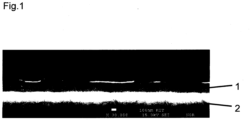
- Fig.1 a light micrograph (incident light) of the cross section of a substrate 2 coated with a single-phase layer 1 of an intermetallic compound of the type Al 13 Fe 4.
- the layer thickness is approximately 270 nm.
- the method according to the embodiment for producing a single-phase layer of intermetallic compounds of the type Al 13 Fe 4 on a structured metal foil as a substrate includes the following procedural steps: - Provision of a substrate made of an iron-based alloy (material number 1.4435) - Optional cleaning of the substrate in an ultrasonic bath in ethanol. - Optional heating of the substrate, preferably at 650°C in air, whereby an oxide adhesion promoter layer forms on the surface to be coated. - Positioning the substrate in a process chamber of a DC magnetron sputtering system, with a cathode with a surface made of the intermetallic compound Al 13 Fe 4 facing the substrate being arranged in the process chamber.
- the substrate was fixed to a substrate holder with retaining clips so that the substrate holder and the target (cathode) were parallel to each other during the subsequent coating process.
- the distance between the two was approximately 6 cm in the exemplary embodiment.
- This step preferably takes place after the substrates have been installed and the process chamber has been evacuated.
- Evacuation of the process chamber preferably to 3.9 ⁇ 10 -4 Pa.
- Optional heating of the process chamber preferably for 30 minutes, to a temperature between 200°C and 500°C.
- the process chamber was heated during evacuation, it will be cooled to room temperature in the evacuated state.
- H 2 glow discharge is used to clean the surfaces of the process chamber, the substrate and the target.
- a hydrogen plasma is generated, whereby the substrate with the substrate holder in the sample chamber performs a rotational movement and passes through the plasma.
- the process chamber is evacuated.
- argon is introduced into the process chamber and an argon plasma is generated.
- the material components of the cathodes are simultaneously transferred into a plasma and the material components are simultaneously deposited on the surface of the aperture.
- the ignited argon plasma is maintained and the aperture between the substrate and target is removed so that the material components from the plasma are simultaneously deposited to form a layer of the intermetallic compound Al 13 Fe 4 with a single-phase structure on the substrate. This is supported by applying a BIAS voltage to the substrate.
- the measured voltage during the sputtering process was 641 V with a deviation of less than 0.5%.
- the target was cooled from the back with cooling water (16°C).
- the process chamber was not heated.
- the deposition rates of the Al 13 Fe 4 target were determined in preliminary tests. Therefore, the process parameters were selected so that a deposition rate of about 7 nm per minute was achieved and thus the expected layer thickness after 40 minutes of sputtering was 270 nm.
Landscapes
- Chemical & Material Sciences (AREA)
- Engineering & Computer Science (AREA)
- Chemical Kinetics & Catalysis (AREA)
- Materials Engineering (AREA)
- Mechanical Engineering (AREA)
- Metallurgy (AREA)
- Organic Chemistry (AREA)
- Physics & Mathematics (AREA)
- Plasma & Fusion (AREA)
- Analytical Chemistry (AREA)
- Physical Vapour Deposition (AREA)
Description
- Die Erfindung betrifft ein Verfahren zur Herstellung einer einphasigen intermetallischen Schicht einer intermetallischen Verbindung eines einphasigen Katalysatormaterials vom Typ GaxPdy oder Al13Fe4 auf einem Substrat gemäß des ersten Patentanspruchs. GaxPdy wird vorzugsweise durch GaPd2 gebildet. Einphasige intermetallische Verbindungen, insbesondere katalytisch aktive Partikel und Beschichtungen aus intermetallischen Verbindungen vom Typ GaPd2 und Al13Fe4 sind als Katalysatormaterialien grundsätzlich bekannt.
- Ein charakteristisches Einsatzgebiet für katalytisch aktive Beschichtungen generell bieten strukturierte Reaktoren, bei denen die katalytisch aktive Beschichtung auf einem strukturierten Substrat mit hoher Oberfläche pro Volumen im Reaktor angeordnet wird, um dadurch eine gute Zugänglichkeit der katalytisch wirksamen Oberfläche zu erreichen. Dies führt zu einem intensiven Kontakt zwischen den strömenden Reaktanden und dem Katalysator, wodurch Stofftransportwiderstände minimiert werden und eine hohe Reaktionsgeschwindigkeit sowie eine hohe Selektivität erreicht werden können. Es existiert eine große Vielfalt solcher strukturierter Substrate. Beispielhaft genannt seien hier metallische Netze, metallische oder keramische Fasergeflechte und Folien mit eingearbeiteten Kanalstrukturen, die quer zur Hauptströmungsrichtung typischerweise Abmessungen im Bereich von einigen Mikrometern bis hin zu einigen Millimetern aufweisen. Insbesondere aus den zuletzt genannten Folien lassen sich, z.B. durch alternierendes Stapeln von Reaktions- und Kühl-/Heizfolien, sogenannte Mikrostrukturreaktoren aufbauen, die zusätzlich zu den minimierten Stofftransportwiderständen zwischen Fluid und Katalysator auch eine sehr hohe Wärmeübertragungsleistung von dem reagierenden Fluid auf ein Wärmeträgerfluid oder umgekehrt ermöglichen. Diese wiederum ist Voraussetzung für eine gute Temperaturkontrolle, die sich günstig auf Ausbeute und Standzeit der Katalysatoren auswirkt, und ebenso für eine effiziente Verwertung der bei der Reaktion freigesetzten Wärme etwa zur Erzeugung von Prozessdampf oder auch effiziente Zuführung der für die Reaktion benötigten Wärme.
- Exotherme Hydrierrungen, wie beispielsweise die an intermetallischen Verbindungen vom Typ GaPd2 oder Al13Fe4 vorteilhaft durchgeführte Semi-Hydrierung von Acetylen, stellen eine wichtige Klasse von Reaktionen dar, die in strukturierten Reaktoren vorteilhaft durchgeführt werden kann.
- Beispielsweise offenbart
EP 1 339 485 B1 einen Mikrostrukturreaktor zur Durchführung einer chemischen Reaktion zwischen jeweils zwei Reaktionspartnern, die als Edukte separat in den Mikrostrukturreaktor einführbar und nach erfolgter Reaktion als Produkt daraus abführbar sind. Der Reaktor selbst besteht aus einem abwechselnd schichtweisen Aufbau von flach ausgebildeten, d.h. aus strukturierten Folien bestehenden Strömungskanalmodulen in Mikrostrukturtechnik, wobei jeweils ein erstes Strömungskanalmodul mit Strömungskanälen, die einen Eingang und einen Ausgang aufweisen, für ein erstes Edukt vorgesehen ist, und jeweils ein zweites Strömungskanalmodul mit Strömungskanälen, in die ein zweites Edukt von außen einführbar ist. - Auch die
DE 10 2005 022 958 B3 offenbart einen Mikrostrukturreaktor, in diesem Fall zur Durchführung einer chemischen zweiphasigen Hydrierung zwischen zwei Reaktanden. Die Vorrichtung weist einen schichtweisen Aufbau mit strukturierten Folien auf und umfasst eine erste Passagenfraktion mit Kanälen für eine Fluidfraktion, die über eine Vielzahl von Öffnungen in mindestens ein mit einer Schüttung von Partikeln eines Katalysators aufgefüllten Reaktionsvolumen ausmündet. - Einen schichtweisen Aufbau eines Mikrostrukturreaktors zeigt auch
DE 10 2012 100 344 A1 . Das eigentliche Reaktionsmodul ist dabei als separates Modul und Träger für einen Katalysator als Einschub in den Mikroreaktor ausgestaltet. - D. Y. CHEN et al."Thermally stable PdIn ohmic contacts to n-GaAs via exchange mechanism", JOURNAL OF APPLIED PHYSICS, 81(1) (1997) Seite 297, XP012041096, ISSN: 0021-8979, DOI: 10.1063/1.363848, offenbart ein Beschichtungsverfahren, wobei eine einphasige PdIn-Schicht mittels DC-Magnetronsputterprozesses eines PdIn-Verbindungstargets in einer Ar-Atmosphäre abgeschieden wird. M. HUANG et al. "Grain growth in sputtered nanoscale PdIn thin films", THIN SOLID FILMS, 449 (1-2) (2004) Seiten 113-119, XP004490649,ISSN: 0040-6090, DOI: 10.1016/ J.TSF.2003.10.081, offenbart ein Beschichtungsverfahren, das ein einphasiger PdIn Target für den DC-Magnetronsputterprozess in einer Ar-Atmosphäre für die Beschichtung eines Salzsubstrates verwendet, und ein einphasiges kubisches Gefüge der PdIn-Schicht.
US 6 159 625 A offenbart ein Verfahren zur Herstellung eines gesinterten Targets aus einer intermetallischen Verbindung und ein magnetisches Aufzeichnungsmedium, das mindestens eine durch Sputtern des gesinterten Targets abgeschiedene Schicht umfasst. - Eine grundsätzliche Problematik bei einem Einsatz katalytisch aktiver Beschichtungen in strukturierten Reaktoren stellt deren Herstellung dar, insbesondere dann wenn es sich um spezielle Materialien wie intermetallische Verbindungen vom Typ GaPd2 oder Al13Fe4 handelt, deren Synthese mit hoher spezifischer Oberfläche besonders aufwändig ist.
- Aktuell gibt es kein Verfahren um einphasige, dünne, intermetallische GaPd2 und Al13Fe4 Schichten im Schichtdickenbereich weniger Nanometer bis zu einigen Mikrometern herzustellen.
- Derzeit kann die intermetallische Verbindung GaPd2 in nanopartikulärer Form synthetisiert werden. Die so erhaltenen Nanopartikel können in eine druckbare Suspension überführt werden und z.B. mittels eines Tintenstrahl- oder Siebdruckverfahrens als Wandbeschichtungen in präformierte Mikrostrukturen gedruckt werden. Im Falle des Druckens von ungeträgerten Nanopartikeln, entsteht jedoch keine Schichtausbildung im eigentlichen Sinne. Stattdessen, werden die Nanopartikel sehr fein und präzise auf der Oberfläche der Mikrostruktur verteilt. Im Fall der Nutzung eines Trägermaterials und des Druckens von auf z.B. Al2O3-geträgerten GaPd2-Nanopartikeln können durch Drop-on-demand Tintenstrahldruck poröse Wandbeschichtungen einstellbarer Dicke im Bereich von 1 - 10 um erzeugt werden. Allerdings sind neben der zeitintensiven Nanopartikelsynthese und der sich anschließenden komplexen Tintenformulierung weitere Nachteile des Tintenstrahldruckens von GaPd2, dass eine großflächige Beschichtung von Substraten nur mit einer sehr langen Druckzeit möglich ist, ein kontrollierter Trocknungsschritt notwendig ist sowie keine kompakte Schichtbildung mit sehr stark ausgeprägter Schichthaftung erzeugt werden kann. Weiterhin können bislang nicht alle intermetallischen Verbindungen in nanopartikulärer Form dargestellt werden (z. B. Al13Fe4). Zur Anwendung des Tintenstrahldrucks sind jedoch Partikel mit einem Durchmesser kleiner 1 µm notwendig. Aufgrund dieser Einschränkungen besteht der Bedarf nach einem einfacheren und kostengünstigeren Verfahren zur Synthese katalytisch aktiver Schichten aus den genannten Materialien.
- Insbesondere die vorgenannten intermetallischen Katalysatormaterialien vom Typ GaPd2 oder Al13Fe4 erfordern für eine zuverlässige Funktion das Vorliegen einer einphasigen Modifikation mit spezifischer Kristallstruktur. Die Ausbildung der intermetallischen Verbindung ist essenziell, da durch die Bildung des charakteristischen Kristallgitters eine Isolierung der katalytisch aktiven Zentren sowie eine Änderung der elektronischen Struktur im Vergleich zu den Elementar- bzw. Legierungsverbindungen erfolgt (M. Armbrüster, K. Kovnir, M. Behrens, D. Teschner, Y. Grin, R. Schlögl, J. Am. Chem. Soc. 2010, 132, 14745-14747 und M. Armbrüster, K. Kovnir, M. Friedrich, D. Teschner, G. Wowsnick, M. Hahne, P. Gille, L. Szentmiklosi, M. Feuerbacher, M. Heggen, F. Girgsdies, D. Rosenthal, R. Schlögl, Y. Grin, Nat. Mater. 2012, 11, 690-693). Diese Effekte führen zu den katalytisch vorteilhaften Eigenschaften bei der Semi-Hydrierung von Acetylen wie beispielsweise einer erhöhten Aktivität und Selektivität im Vergleich zu konventionellen Palladium- oder Legierungskatalysatoren.
- Davon ausgehend liegt eine Aufgabe der Erfindung darin, ein Verfahren zur Herstellung einer einphasigen intermetallischen Schicht aus intermetallischen Verbindungen insbesondere vom Typ GaxPdy und Al13Fe4 auf ein Substrat vorzuschlagen, das sich insbesondere für eine einfache und kostengünstige sowie auch großflächige Beschichtung strukturierter Substrate wie z.B. mikrostrukturierter Folien, metallischer Netze, metallischer oder keramischer Fasern und Fasergeflechte und 3D-gedruckter Strukturen eignet.
- Gelöst wird die Aufgabe durch ein Verfahren mit den Merkmalen des Anspruchs 1. Hierauf rückbezogene Unteransprüche geben vorteilhafte Ausgestaltungen wieder.
- Die Lösung der Aufgabe basiert auf einem Verfahren zur Herstellung einer einphasigen Schicht intermetallischer Verbindungen vom Typ GaxPdy, vorzugsweise GaPd2, oder Al13Fe4 auf ein Substrat mittels eines DC Magnetron-Sputterverfahrens. Die besondere Schwierigkeit liegt darin, den Sputtervorgang so zu gestalten, dass die Zusammensetzung der intermetallischen Phase über die ganze Schicht sichergestellt ist. Hierzu wird der Einsatz mindestens eines, vorzugsweise genau eines Sputtertargets vorgeschlagen, wobei jedes der im Sputtervorgang eingesetzten Sputtertargets zumindest in der Tiefe, die während des Sputter-Prozesses genutzt wird, vollständig und auch im atomaren Bereich homogen jeweils einphasig nur aus einer der intermetallischen Verbindungen vom Typ GaPd2 oder Al13Fe4 gebildet wird.
- Ein Sputtertarget ist eine Kathode mit einem Festkörper mit Kathodenfläche aus der vorgenannten einphasigen intermetallischen Verbindung. Erfindungsgemäß ist das Sputtertarget als Schicht aus der einphasigen intermetallischen Verbindung auf einen metallischen Grundkörper als Trägerelement aufgebracht. Im Bereich der Kontaktfläche zu dem das Sputtertarget tragenden Grundkörper, vorzugsweise aus Kupfer, kann es zur Ausbildung einer oder mehrerer ternärer Phasen kommen. Diese sind jedoch nicht am Sputterprozess beteiligt und daher insoweit unschädlich.
- Wesentlich ist, dass die intermetallische Verbindung einer Elementkombination, vom Typ GaxPdy, vorzugsweise GaPd2, oder Al13Fe4, in der Schicht einphasig vorliegt und sich nicht auf zwei oder mehrere unterschiedliche in der Schicht befindliche Phasen aufteilt.
- Wesentlich ist auch die Verwendung eines oder mehrerer Sputtertargets, im obigen Sinne jeweils bestehend aus einer intermetallischen Verbindung, erfindungsgemäß der abzuscheidenden intermetallischen Verbindung.
- Eine intermetallische Verbindung vom Typ GaPd2 oder Al13Fe4 ist im Rahmen dieser Patentanmeldung definiert als eine intermetallische Verbindung, die sich aus, vorzugsweise nur den Verbindungen GaPd2 oder Al13Fe4 zusammensetzt. Sie umfasst vorzugsweise keine zusätzlichen Dotierungselemente.
- Eine einphasige Schicht intermetallischer Verbindungen vom Typ GaPd2 oder Al13Fe4 ist definiert als eine Schicht, in der die intermetallische Verbindung einphasig vorliegt. Davon unberührt kann die einphasige Schicht auch weitere mögliche Phasen z.B. aus Verunreinigungen, die aber nicht aus den Elementkombinationen der intermetallischen Verbindung bestehen, enthalten. Vorzugsweise besteht die einphasige Schicht intermetallischer Verbindungen jedoch nur aus der intermetallischen Verbindung vom Typ GaPd2 oder Al13Fe4 und enthält vorzugsweise keine zusätzlichen Dotierungselemente.
- Die Einphasigkeit der Schicht ist mittels Röntgenstrukturanalyse (XRD) überprüfbar, ohne dass dabei das Material zwingend bis in den atomaren Bereich hin aufgeklärt werden muss. Die Phasenzusammensetzung wird in den Diffraktogrammen wiedergegeben, wobei die Einphasigkeit durch das ausschließliche Auftreten der charakteristischen Reflexe im Diffraktogramm nachweisbar ist.
- Nur ein Gleichstrom (DC) Magnetron-Sputterverfahren mit einem einphasigen intermetallischen Sputtertarget intermetallischer Verbindungen im obigen Sinne vorzugsweise vom Typ GaPd2 bzw. Al13Fe4 ermöglicht bislang auf technisch einsetzbaren Trägermaterialien eine Herstellung von einphasigen intermetallischen Schichten aus derartigen Systemen im Schichtdickenbereich unterhalb von 10 µm bis zu wenigen Nanometern, vorzugsweise zwischen 5 oder 10 und 500 oder 1000 nm.
- Das Verfahren umfasst die folgenden Verfahrensschritte:
- Bereitstellung eines Substrats, vorzugweise aus einem nichtmetallischen anorganischen Werkstoff, vorzugsweise Glas, einem strukturierbaren Halbleiter, vorzugsweise Silizium, oder einem Metall, vorzugsweise eine Eisenbasislegierung wie einem Chrom-Nickel-Stahl,
- Positionieren des Substrats in einer Prozesskammer einer DC Magnetron-Sputteranlage und Evakuierung der Prozesskammer, wobei in der Prozesskammer mindestens je eine Kathode (d.h. ein Sputter-Target) mit einer zum Substrat weisenden Oberfläche aus einer intermetallischen Verbindung vorzugsweise vom Typ GaxPdy oder Al13Fe4 angeordnet ist, wobei GaxPdy weiter bevorzugt durch GaPdz gebildet wird,
- Nutzung eines hochreinen Edelgases (z. B. Argon) als Sputtergas unter Zusatz von Wasserstoff zur Reinigung der Oberfläche des Substrats und des Sputter-Targets,
- simultane Überführung von Materialbestandteilen aus den Kathoden (d.h. den Sputter-Targets) in ein Plasma,
- simultanes Abscheiden der Materialbestandteile aus dem Plasma zu einer Schicht aus einer intermetallischen Verbindung bevorzugt vom Typ GaPd2 oder Al13Fe4 mit einphasigem Gefüge auf dem Substrat sowie
- Entnahme des Substrats mit der abgeschiedenen Schicht aus der betreffenden intermetallischen Verbindung aus der Prozesskammer.
- Wesentlich ist, dass die intermetallische Verbindung in den Kathoden einphasig vorliegt, und zwar auch bis in den atomaren Bereich. Ein bevorzugtes Verfahren sieht daher eine Aufnahme der Herstellung der Kathoden in das Verfahren vor.
- Ein Einsatz von einphasig vorliegenden intermetallischen Verbindungen als Ausgangsmaterial ermöglicht die Herstellung von Targets aus intermetallischen Verbindungen, beispielsweise von GaPd2- bzw. Al13Fe4-Targets.
- Weiter bevorzugt erfolgt die Herstellung der Kathoden mittels einer Oberflächendiffusion behafteten Transportumlagerung wie z.B. eines Sinterprozesses aus einem Pulver aus der intermetallischen Verbindung, vom Typ GaxPdy oder Al13Fe4, wobei GaxPdy weiter bevorzugt durch GaPd2 gebildet wird.
- Nicht zwingend, aber weiter bevorzugt wird das intermetallische Pulver für den vorgenannten Sinterprozess einphasig synthetisiert, weiter bevorzugt mittels einer Festkörpersynthese gewonnen.
- Mittels eines bevorzugt beim vorgenannten Sinterprozess bei der Herstellung der Kathoden (Sputter-Targets) zur Anwendung kommenden Spark-Plasma-Sinterns sind Sputter-Targets dieser intermetallischen Verbindungen einphasig herstellbar.
- Bei diesem Verfahren wird das jeweilige intermetallische Pulver in einem ersten Schritt direkt auf dem bevorzugt metallischen Grundkörper zu einem Grünkörper vorverdichtet. Dies erfolgt mechanisch, wobei in einer bevorzugten Ausgestaltung der Grundkörper als Pressstempel in einer Kolbenführung ausgestaltbar und einsetzbar ist. In einem zweiten Schritt erfolgt eine Überführung des Grünkörpers in eine Schutzgasatmosphäre oder ein Vakuum in einen Sinterofen. In diesem erfolgt der eigentliche Sintervorgang, bei dem zunächst weiterer mechanischer Druck auf den Grünkörper aufgeprägt wird und mit diesem der Grünkörper weiter mechanisch verdichtet wird. Unter Beibehaltung dieses weiteren Drucks erfolgt der eigentliche Sintervorgang, bei dem im Grünkörper mittels eines direkten Stromdurchgangs (Gleichstrom) Wärme erzeugt und dieser aufgeheizt wird. Durch viskoses Fließen oder durch (partielles) Aufschmelzen unter hohem Druck insbesondere an den Kontaktbereichen zwischen den Partikeln und anschließendes Abkühlen der Partikel kommt es zur Verschmelzung dieser und damit des Pulvers im Grünkörper. Zugleich kommt es zu einer vorzugsweise stoffschlüssigen Verbindung mit dem Grundkörper der Kathoden (z.B. Kupferplatte) aufgrund atomarer Umlagerungsprozesse durch Diffusion bei der Sinterung. Gegenüber einem herkömmlichen Sintern wird der Grünkörper in vorteilhafter Weise nicht von außen beheizt, sondern durch den direkten Stromdurchgang, d.h. im gesamten Volumen des Grünkörpers.
- Der Vorteil in diesem Verfahren liegt darin, dass die Heiz- bzw. Kühlrampen bis hin zu Werten um 1000 K/min wie auch kurze Prozesszeiten (Bereich < 30 min) bei hoher Kompaktierung (> 90 % theoretischer Dichte) realisierbar sind. Durch das vorgenannte Spark-Plasma-Sintern werden die bevorzugt als intermetallische Verbindung vorliegenden Partikel unterhalb des eigentlichen Schmelzpunkts eines Festkörpers aus dem gleichen Material kompaktiert; kristalline Phasen der Partikel werden im Idealfall ohne eine Phasenänderung in das Target überführt.
- Die Kolbenführung weist als eine Voraussetzung einer Durchführbarkeit des Spark-Plasma-Sinterns eine elektrische Leifähigkeit unterhalb des Grünkörpers auf und darf keine stoffschlüssige Verbindung mit dem Sinterkörper eingehen (z.B. Kolbenführung aus einer Nicht-Oxid-Keramik).
- Die bevorzugte Verwendung des Spark-Plasma-Sinterns dient dabei ausschließlich zur Herstellung der intermetallischen Sputter-Targets. Wesentlich bei einer Anwendung für intermetallische Verbindungen ist, dass insbesondere aufgrund der hohen Aufheiz- und Abkühlraten, vorzugsweise zwischen 29 K/min und 100 K/min, und der damit erforderlichen kurzen Prozesszeiten (Sinterzeiten vorzugsweise ca. 60 min für GaPd2 und ca. 30 min für Al13Fe4) eine Bildung anderer Phasen wie z.B. andere intermetallische Verbindungen neben der gewünschten Zielverbindung vermieden oder zumindest behindert wird.
- Vorteilhaft beim Aufbau der Kathoden aus einer einphasigen intermetallischen Verbindung mittels Spark-Plasma-Sintern ist eine Begrenzung der Sintertemperatur, vorzugsweise 920 bis 980°C, vorzugsweise 950°C, vorzugsweise 200 bis 300 K unterhalb des Schmelzpunktes, und des dabei anliegenden Drucks (vorzugsweise ca. 200-300 K unterhalb des Schmelzpunktes). Sowohl eine steigende Sintertemperatur als auch ein steigender Druck erhöhen die Gefahr einer ungewünschten Phasenumwandlung und damit einhergehend die Gefahr einer Bildung einer •zweiten Phase. Insbesondere bei einem zu hohen Druck kommt es beispielsweise ab 60 MPa zu einer Phasenumwandlung von Al13Fe4, d.h. zu einer Zersetzung zur im Phasendiagramm benachbarten intermetallischen Verbindung Al5Fe2.
- Eine Anwendung des Spark-Plasma-Sinterns zur Herstellung einphasiger intermetallischer Verbindungen als Sputtertargets ist im Rahmen des Stands der Technik weder für das System Al-Fe noch für das System Ga-Pd bekannt.
- Erfindungsgemäß besteht mindestens eine oder mehrere Kathoden aus der abzuscheidenden intermetallischen Verbindung, vom Typ GaxPdy oder Al13Fe4. Dabei kann diese Schicht vorzugsweise auf einem Grundkörper aufgesintert werden. Der Grundkörper ist zur Sicherstellung eines ausreichenden Wärmeaustausches zwischen Schicht und einer Wärmesenke oder Quelle vorzugsweise an der Substrathalterung aus einem guten Wärmeleiter, vorzugsweise einem Metall, weiter bevorzugt aus Kupfer oder Silber hergestellt. Eine bevorzugte Ausgestaltung der Grundkörper der Kathoden sehen für die aufgesinterte Schicht ebene, vorzugsweise auch runde Flächen vor.
- Die Herstellung dünner intermetallischer Schichten mittels DC Magnetron-Sputtern unter Nutzung des vorgenannten intermetallischen Sputter-Targets ermöglicht eine direkte Synthese intermetallischer Schichten. In vorteilhafter Weise erfolgt dabei der Beschichtungsvorgang grundsätzlich ohne eine Phasentransformation unter Beteiligung von Gasphasen-Atomclustern, die aus dem Sputter-Target herausgeschlagen werden, die wiederum eine potentielle Ursache für eine Bildung mehreren Phasen in der Beschichtung darstellen würde. Weiterhin eignet sich dieses Vorgehen in besonderer Weise für die einphasige Beschichtung auch großflächigerer Substrate. Weitere Vorteile sind die vergleichsweise einfache und schnelle Durchführung, der Verzicht auf Lösemittel und dementsprechend kein Anfall flüssiger Abfälle, vergleichsweise geringe Materialkosten und die Möglichkeit mit Hilfe von Masken auf relativ einfache Weise dafür sorgen zu können, dass die Beschichtung nur auf vorgesehenen Stellen erfolgt.
- Eine bevorzuge Ausgestaltung des Verfahrens umfasst eine Auslagerung des Substrats mit der über das Verfahren, vorzugsweise mittels des vorgenannten DC Magnetron-Sputterverfahrens abgeschiedenen intermetallischen Schicht bei einer Temperatur zwischen 300 und 900°C, einem Temperaturbereich, in dem in der vorgenannten abgeschiedenen intermetallischen Verbindung Diffusion, d.h. atomare Umlagerung stattfindet, jedoch oberhalb der Tamman-Temperatur, des Beginns der inneren Diffusion bei Kristallen. Eine Auslagerung ist insbesondere für Al13Fe4 vorteilhaft, beim Typ GaxPdy und insbesondere GaPd2, vor allem für dünne Schichten. Im Rahmen von Ausführungsbeispielen erfolgte eine zufriedenstellende Auslagerung von GaPd2 unter inertem oder reduktivem Gas (Edelgas, N2, H2), vorzugsweise Formiergas (Ar und Ar/ 5% H2) bei 400 bis 500°C, vorzugsweise 450°C sowie von Al13Fe4 bei 300 bis 850°C. Die Heiz-/Kühlraten wurden im Bereich zwischen 1 bis 5 K/min eingestellt. Durch die Diffusion werden insbesondere überschüssige Kristallisationskeime abgebaut.
- Eine bevorzuge Ausgestaltung des Verfahrens umfasst eine Vorbereitung des Substrats vor dem Positionieren des Substrats in einer Prozesskammer einer DC Magnetron-Sputteranlage. Die Vorbereitung umfasst das Aufbringen einer Haftvermittlerschicht auf dem Substrat. Die Haftvermittlerschicht ist vorzugsweise eine oxidische Haftvermittlerschicht, die weiter bevorzugt aus einem Oxid des Materials des Substrats, vorzugsweise ein Metall (vorzugsweise Aluminium und Aluminiumlegierungen, Edelstähle, rostfreie Stähle, Cr-Ni-Legierungen wie Inconel, Hastteloy, Nicrofer etc.) besteht. Die Zusammensetzung der sich ausbildenden Oxidschicht hängt mit dem gewählten Material zusammen. Des Weiteren hängt die Materialauswahl mit der chemischen Reaktion und den Reaktionsbedingungen zusammen. Das Verfahren zur Herstellung dieser Haftvermittlerschicht umfasst hierfür einen bevorzugten Verfahrensschritt, bei dem das Substrat vor dem Positionieren des Substrats in einer Prozesskammer einer DC Magnetron-Sputteranlage zur Ausbildung der genannten oxidischen Haftvermittlerschicht auf dem Substrat unter einer sauerstoffhaltigen Atmosphäre wie z.B. Luft oder Sauerstoff mit einer materialabhängigen Temperatur zwischen 500 und 1000°C, vorzugsweise 600 bis 700°C aufgeheizt wird.
- Weitere Prozessparameter und Verfahrensschritte wie Substratvorbehandlung und -konditionierung mittels Wasserstoff- und Argonplasma, Substratanordnung (Abstand und Winkel zum Target), Sputter- und Targettemperatur, BIAS-Spannung, Pulsform sowie Anwendung von DC-, RF- oder Ionisierungssputtern sind für eine Erzielung einer einphasigen Schicht aus intermetallischen Verbindungen auf einem Substrat geeignet einzustellen. Vorteilhaft sind: Argondruck pAr (vorzugsweise 0,1 bis 5 Pa), Magnetronleistung P (vorzugsweise 20 bis 2000W) und Sputterzeit t (ab 1 min). Der Druck des Argongases hat einen Einfluss auf die Sputterrate. Mit steigendem Druck nimmt die Sputterrate zu, da mehr effektive Argonion-Target-Kollisionen stattfinden. Ab einer gewissen Höhe wird die Sputterrate wieder geringer, da die Wahrscheinlichkeit zunimmt, dass die abgelösten Targetatome und -cluster im Plasma auf ein Argonion treffen und somit die Substratoberfläche nicht mehr erreichen können. Die Magnetronleistung hat einen Einfluss auf das Plasma und die Energie mit der die Argonionen auf das Target treffen und somit auch einen Einfluss auf die Sputterrate. Mithilfe der Sputterzeit lässt sich die Schichthöhe skalieren.
- Diese Prozessparameter haben einen Einfluss auf die chemische Zusammensetzung und/oder die strukturellen Eigenschaften der gesputterten Schichten. Die bevorzugten Werte hierzu sind teilweise von der Anlage abhängig. Im Beispiel betrug der Sputtertarget-Substratabstand ca. 6 bis 30 cm, weiter bevorzugt ein Abstand von 6 bis 10 cm. Der Ausrichtung des Substrates zum Target ist mit einem Winkel zwischen 0° (parallel) und 90° (senkrecht) realisierbar. Vorzugsweise wird ein Winkel von 0° verwendet. Die maximale Temeperatur liegt bei 300°C. Die Sputterversuche wurde vorzugsweise ohne eine Tempererierung oder zusätzliche Beheizung durchgeführt. Erfahrungsgemäß erhitzt sich das Substrat in Abhängigkeit der Sputterleistung und -dauer auf Temperaturen zwischen 20 bis 70°C. Die Es wurden eine rechteckige Monpuls-Form verwendet. Es wurden weiter bevorzugt Argondrücke von 0,4 bis 1,4 Pa, Magnetronleistungen von 80 bis 140 W und Sputterzeiten von 1 bis 390 min verwendet.
- Ein wesentlicher Unterschied des vorgeschlagenen Verfahrens zu herkömmlichen Verfahren liegt in der erstmaligen Verwendung eines intermetallischen Sputter-Targets für die einphasige Beschichtung eines Substrats mit einer intermetallischen Verbindung, bevorzugt vom Typ GaPd2 oder Al13Fe4, im Rahmen eines DC Magnetron-Sputterverfahrens. Der Nachweis der Einphasigkeit der abgeschiedenen intermetallischen Schicht ist sowohl für Al13Fe4 als auch für GaPd2 mittels Pulverröntgendiffraktion erbringbar. Ferner ist erst durch die Verwendung von intermetallischen Sputter-Targets die einphasige Herstellung speziell von intermetallischen GaPd2- und Al13Fe4-Schichten überhaupt möglich.
- Die Besonderheit des vorgeschlagenen Verfahrens begründet sich darin, dass die auf dem Substrat abgeschiedene einphasige Schicht aus einer intermetallischen Verbindung bereits im Sputtertarget vorliegt und während der Ionisation beim Sputtern in Cluster-Form in die Gasphase übergeht. Dadurch muss sich bei der Abscheidung auf dem Substrat nicht erst die intermetallische Verbindung bilden. Insbesondere für die intermetallische Verbindung Al13Fe4 wird mit diesem Vorgehen die Bildung einer thermodynamisch gegenüber der intermetallischen Verbindung Al13Fe4 stabileren Nachbarphase wie z.B. AlsFez wirksam unterdrückt.
- Das Verfahren eignet sich insbesondere für die Herstellung katalytisch beschichteter strukturierter Elemente für chemische Reaktoren, vorzugsweise auf Basis mikrostrukturierter (Strukturhöhen und -breiten im Mikrometermaßstab, d.h. kleiner 1 mm, vorzugsweise kleiner 500 um) Metallfolien oder metallischer Netze und Fasergeflechte mit einer einphasigen Beschichtung aus einer intermetallischen Verbindung.
- Das Verfahren wird anhand eines Ausführungsbeispiels mit der folgenden Figur näher erläutert. Die Figur, die Beschreibung und die Ansprüche enthalten Merkmale auch in Kombination. Der Fachmann wird die Merkmale zweckmäßigerweise auch einzeln betrachten und zu sinnvollen weiteren Kombinationen zusammenfassen.
-
Fig.1 eine lichtmikroskopische Aufnahme (Auflicht) des Querschliffs eines mit einer einphasigen Schicht 1 aus einer intermetallischen Verbindung des Typs Al13Fe4 beschichteten Substrats 2. Die Schichtdicke beträgt ca. 270 nm. - Das Verfahren gemäß des Ausführungsbeispiels zur Herstellung einer einphasigen Schicht aus intermetallischen Verbindungen des Typs Al13Fe4 auf einer strukturierten Metallfolie als Substrat, wie es gemäß des Schliffbildes nach
Fig.1 dargestellt ist, umfasst folgende Verfahrensschritte:
- Bereitstellung eines Substrats aus einer Eisenbasislegierung (Materialnummer 1.4435)
- Optionale Reinigung des Substrats in einem Ultraschallbad in Ethanol.
- Optionale Aufheizung des Substrats vorzugsweise bei 650°C an Luft, wobei sich auf der zu beschichtenden Oberfläche eine oxidische Haftvermittlerschicht ausbildet.
- Positionieren des Substrats in einer Prozesskammer einer DC Magnetron-Sputteranlage, wobei in der Prozesskammer eine Kathode mit einer zum Substrat weisenden Oberfläche aus der intermetallischen Verbindung Al13Fe4 angeordnet ist. Das Substrat wurde auf einem Substrathalter mit Halteklammern so fixiert, dass sich der Substrathalter und das Target (Kathode) während des nachfolgenden Beschichtungsvorgangs parallel zueinander befinden. Der Abstand zwischen beiden betrug im Ausführungsbeispiel ca. 6 cm. Dieser Schritt findet vorzugsweise nach dem Einbau der Substrate und der Evakuierung der Prozesskammer statt.
- Evakuierung der Prozesskammer bis auf bevorzugt 3,9·10-4 Pa.
- Optionale Aufheizung der Prozesskammer vorzugsweise für 30 min auf eine Temperatur zwischen vorzugsweise 200°C und 500°C.
- Sofern die Prozesskammer während der Evakuierung aufgeheizt wurde, erfolgt die Abkühlung auf Raumtemperatur im evakuierten Zustand.
- Prozessablauf des Sputterns, umfassend die seriellen Teilschritte der H2-Glimmentladung, des Vorsputterns und des Sputterns, wobei im Ausführungsbeispiel die in nachfolgender Tabelle 1 subsumierten Prozessparameter für die einzelnen Schritte des Prozessablaufs angewandt wurden.
- Die H2-Glimmentladung dient zur Reinigung der Oberflächen der Prozesskammer, des Substrates und des Targets. Nach Einleitung von Wasserstoff in die Prozesskammer wird ein Wasserstoffplasma erzeugt, wobei das Substrat mit dem Substrathalter im Probenraum eine Rotationsbewegung durchführt und dabei das Plasma durchstreift. Während des Glimmens befindet sich keine Blende zwischen Target und Substrat. Im Anschluss an das Glimmen wird die Prozesskammer evakuiert. Für das Vorsputtern wird Argon in die Prozesskammer eingeleitet und ein Argonplasma erzeugt. Dabei befindet sich eine Blende zwischen Substrat und Target. Es erfolgt eine simultane Überführung von Materialbestandteilen der Kathoden in ein Plasma und ein simultanes Abscheiden der Materialbestandteile auf der Oberfläche der Blende.
- Für das Sputtern wird das gezündete Argonplasma aufrechterhalten und die Blende zwischen Substrat und Target entfernt, sodass ein simultanes Abscheiden der Materialbestandteile aus dem Plasma zu einer Schicht aus der intermetallischen Verbindung Al13Fe4 mit einphasigem Gefüge auf dem Substrat erfolgt. Dies wird unterstützt durch Anlegen einer BIAS-Spannung an dem Substrat.
- Entnahme des Substrats mit der abgeschiedenen Schicht aus der intermetallischen Verbindung Al13Fe4 aus der Prozesskammer.Tabelle 1: Prozessablauf zum Sputtern von 270 nm dicken Al13Fe4-Schichten Schritt t [min] BIAS1 [V] P [W] Plasma p [Pa] Blende2 Rotation3 [min-1] H2-Glimmen 15 80-160 100 H2 0,8 180° 1,2 Vorsputtern 10 - 100 Ar 1,0 0° - Sputtern 40 80 100 Ar 1,0 180° - 1 Als Monopuls-A (Rechteckform)
2 Bei Blendenposition 0° befindet sich die Blende zwischen Target und Substrat, bei 180° befindet sich keine Blende zwischen Target und Substrat
3 Es rotiert der Substrathalter inkl. Substrat im Probenraum und durchstreift dabei das Plasma - Die gemessene Spannung während des Sputtervorgangs betrug 641 V mit einer Abweichung von unter 0,5 %. Das Target wurde rückseitig mit Kühlwasser (16°C) gekühlt. Die Prozesskammer wurde nicht beheizt.
- Die Abscheideraten des Al13Fe4-Targets wurden in Vorversuchen bestimmt. Daher waren die Prozessparameter so wählbar, dass eine Abscheiderate von etwa 7 nm je min erzielt wird und somit die zu erwartende Schichtdicke nach 40 min Sputtern 270 nm beträgt.
Tabelle 2: EDX-Ergebnisse zur Bestimmung der Schichtzusammensetzung der Al13Fe4-Schicht Gew.% Σ Atom% Al 58,32 1,89 74,33 Fe 41,68 3,26 25,67
Claims (10)
- Verfahren zur Herstellung einer einphasigen Schicht (1) aus intermetallischen Verbindungen auf einem Substrat (2), umfassenda) eine Bereitstellung eines Substrats,b) ein Positionieren des Substrats in einer Prozesskammer einer DC Magnetron-Sputteranlage und Evakuierung der Prozesskammer, wobei in der Prozesskammer mindestens je eine Kathode mit einer zum Substrat weisenden Oberfläche aus einer intermetallischen Verbindung angeordnet ist,c) eine simultane Überführung von Materialbestandteilen aus den Kathoden in ein Plasma, bei Verwendung eines Edelgases als Sputtergas,d) ein simultanes Abscheiden der Materialbestandteile aus dem Plasma zu einer intermetallischen Schicht mit einphasigem Gefüge auf dem Substrat sowiee) eine Entnahme des Substrats mit der abgeschiedenen intermetallischen Schicht aus der Prozesskammer,
wobeif) die intermetallische Verbindung der mindestens einen Kathode einphasig vorliegt, und zwar auch bis in den atomaren Bereich,g) die einphasige Schicht auch weitere mögliche Phasen z.B. aus Verunreinigungen, die aber nicht aus den Elementkombinationen der intermetallischen Verbindung bestehen, enthalten kann,h) die intermetallische Verbindung eine intermetallische Verbindung vom Typ GaxPdy oder Al13Fe4 sowie die intermetallische Schicht eine intermetallische Schicht vom Typ GaxPdy oder Al13Fe4 ist sowiei) die Einphasigkeit der abgeschiedenen intermetallischen Schicht mittels Röntgenstrukturanalyse (XRD) überprüfbar, wobei die Phasenzusammensetzung in den Diffraktogrammen wiedergegeben wird, wobei die Einphasigkeit durch das ausschließliche Auftreten der charakteristischen Reflexe im Diffraktogramm nachweisbar ist. - Verfahren nach Anspruch 1, dadurch gekennzeichnet, dass das GaxPdy durch GaPd2 gebildet wird.
- Verfahren nach einem der Ansprüche 1 oder 2, umfassend eine Herstellung der Kathoden mittels eines Sinterprozesses aus intermetallischem Pulver aus der intermetallischen Verbindung.
- Verfahren nach Anspruch 3, dadurch gekennzeichnet, dass das intermetallische Pulver einphasig synthetisiert ist.
- Verfahren nach Anspruch 4, dadurch gekennzeichnet, dass das einphasig synthetisierte intermetallische Pulver mittels einer Festkörpersynthese gewonnen wird.
- Verfahren nach einem der Ansprüche 3 bis 5, dadurch gekennzeichnet, dass der Sinterprozess ein Spark-Plasma-Sinterprozess ist.
- Verfahren nach einem der vorgenannten Ansprüche, dadurch gekennzeichnet, dass mindestens eine der Kathoden aus einem metallischen Grundkörper und einer auf diesem aufgesinterten Schicht aus der abzuscheidenden intermetallischen Verbindung besteht.
- Verfahren nach Anspruch 7, dadurch gekennzeichnet, dass der Grundkörper aus Kupfer oder Silber ist.
- Verfahren nach einem der vorgenannten Ansprüche, dadurch gekennzeichnet, dass das Substrat mit der abgeschiedenen intermetallischen Schicht bei einer Temperatur zwischen 300 und 850°C ausgelagert wird.
- Verfahren nach einem der vorgenannten Ansprüche, dadurch gekennzeichnet, dass das Substrat aus einem Metall besteht, das vor dem Positionieren des Substrats in einer Prozesskammer einer DC Magnetron-Sputteranlage zur Ausbildung einer oxidischen Haftvermittlerschicht auf dem Substrat mit einer Temperatur zwischen 600 und 700°C aufgeheizt wird.
Applications Claiming Priority (2)
| Application Number | Priority Date | Filing Date | Title |
|---|---|---|---|
| DE102017116972.5A DE102017116972A1 (de) | 2017-07-27 | 2017-07-27 | Verfahren zur Herstellung einer einphasigen Schicht aus intermetallischen Verbindungen |
| PCT/EP2018/000371 WO2019020214A1 (de) | 2017-07-27 | 2018-07-25 | Verfahren zur herstellung einer einphasigen schicht aus intermetallischen verbindungen |
Publications (2)
| Publication Number | Publication Date |
|---|---|
| EP3658698A1 EP3658698A1 (de) | 2020-06-03 |
| EP3658698B1 true EP3658698B1 (de) | 2024-08-28 |
Family
ID=63113462
Family Applications (1)
| Application Number | Title | Priority Date | Filing Date |
|---|---|---|---|
| EP18750326.3A Active EP3658698B1 (de) | 2017-07-27 | 2018-07-25 | Verfahren zur herstellung einer einphasigen schicht aus intermetallischen verbindungen |
Country Status (3)
| Country | Link |
|---|---|
| EP (1) | EP3658698B1 (de) |
| DE (1) | DE102017116972A1 (de) |
| WO (1) | WO2019020214A1 (de) |
Families Citing this family (1)
| Publication number | Priority date | Publication date | Assignee | Title |
|---|---|---|---|---|
| CN111318801B (zh) * | 2020-03-09 | 2021-07-20 | 中南大学 | 一种基于高熵合金扩散焊接的金属间化合物及其制备方法 |
Family Cites Families (10)
| Publication number | Priority date | Publication date | Assignee | Title |
|---|---|---|---|---|
| US5171642A (en) * | 1989-04-17 | 1992-12-15 | International Business Machines Corporation | Multilayered intermetallic connection for semiconductor devices |
| US6258719B1 (en) * | 1998-07-01 | 2001-07-10 | Honeywell International Inc. | Intermetallic aluminides and silicides articles, such as sputtering targets, and methods of making same |
| JP2989169B2 (ja) * | 1997-08-08 | 1999-12-13 | 日立金属株式会社 | Ni−Al系金属間化合物ターゲットおよびその製造方法ならびに磁気記録媒体 |
| JPH11175947A (ja) * | 1997-12-12 | 1999-07-02 | Hitachi Metals Ltd | 磁気記録媒体および下地層形成用ターゲット |
| DE10044526A1 (de) | 2000-09-04 | 2002-04-04 | Mannesmann Ag | Mikrostrukturreaktor und Verfahren zur Durchführung chemischer Reaktionen |
| AT414128B (de) * | 2004-08-03 | 2006-09-15 | Miba Gleitlager Gmbh | Aluminiumlegierung für tribologisch beanspruchte flächen |
| FR2881757B1 (fr) * | 2005-02-08 | 2007-03-30 | Saint Gobain | Procede d'elaboration par projection thermique d'une cible a base de silicium et de zirconium |
| DE102005022958B3 (de) | 2005-05-19 | 2006-07-20 | Forschungszentrum Karlsruhe Gmbh | Mikrostrukturreaktor und Verwendung desselben |
| DE102012100344A1 (de) | 2012-01-17 | 2013-07-18 | Karlsruher Institut für Technologie | Mikroreaktor für katalytische Reaktionen |
| JP5594618B1 (ja) * | 2013-02-25 | 2014-09-24 | 三菱マテリアル株式会社 | スパッタリングターゲット及びその製造方法 |
-
2017
- 2017-07-27 DE DE102017116972.5A patent/DE102017116972A1/de not_active Ceased
-
2018
- 2018-07-25 EP EP18750326.3A patent/EP3658698B1/de active Active
- 2018-07-25 WO PCT/EP2018/000371 patent/WO2019020214A1/de not_active Ceased
Also Published As
| Publication number | Publication date |
|---|---|
| EP3658698A1 (de) | 2020-06-03 |
| WO2019020214A1 (de) | 2019-01-31 |
| DE102017116972A1 (de) | 2019-01-31 |
Similar Documents
| Publication | Publication Date | Title |
|---|---|---|
| DE60034513T2 (de) | Verfahren zur Herstellung eines Sputtertargets | |
| DE69706643T2 (de) | Verfahren zur herstellung von dünnen schichten eines nicht verdampfbaren gettermaterials auf einem träger | |
| DE102015100665B4 (de) | Verfahren zum Erzeugen einer Metallschicht auf einem Halbleiterkörper unter Verwendung eines Druckprozesses | |
| DE69814560T2 (de) | Nickelpulver und Verfahren zu seiner Herstellung | |
| EP2845920A1 (de) | Oxidverbindungen als Beschichtungszusammensetzung | |
| EP3347303B1 (de) | Verfahren zur herstellung von strukturierten oberflächen | |
| DE2252343A1 (de) | Verfahren zur herstellung von kuenstlichen diamanten | |
| DE102012217191A1 (de) | Herstellen eines Refraktärmetall-Bauteils | |
| EP3308417B1 (de) | Verfahren zur herstellung nanostrukturierter schichten | |
| DE102007049930B4 (de) | Oberflächenmodifizierte Hohlraumstrukturen, Verfahren zu deren Herstellung sowie deren Verwendung | |
| DE3602804C2 (de) | ||
| DE19928807B4 (de) | Verfahren zur Herstellung eines piezoelektrischen/elektrostriktiven Keramik-Mikro-Stellgliedes unter Verwendung von Photolithographie | |
| DE3029171A1 (de) | Verfahren zur herstellung von poroesen metallfilmen | |
| EP0033506B1 (de) | Verfahren zum Herstellen niederohmiger, einkristalliner Metall- oder Legierungsschichten auf Substraten | |
| EP4112587A1 (de) | Verfahren zur herstellung eines metall-keramik-substrats mittels schnellem heizen | |
| EP3172354B1 (de) | Sputtertarget auf der basis einer silberlegierung | |
| DE102017116972A1 (de) | Verfahren zur Herstellung einer einphasigen Schicht aus intermetallischen Verbindungen | |
| EP1250192A2 (de) | Dünnschichtkatalysatoren auf basis von raney-legierungen und verfahren zu deren herstellung | |
| EP3823779A1 (de) | Verwendung von pulvern hochreflektiver metalle für die additive fertigung | |
| WO2024002788A1 (de) | Verfahren zum herstellen eines elektrischen bauteils mittels sukzessivem aufdrucken und sintern von partikelhaltiger tinte | |
| DE69115854T2 (de) | Rost zur thermischen Behandlung mit hoher Temperatur | |
| EP0537501B1 (de) | Verfahren zur Herstellung elektronischer Bauteile aus einem Verbund aus Nichtleiter- und Leiterschichten | |
| DE102019130583A1 (de) | Verfahren zur herstellung eines brennstoffzellenseparators | |
| DE102023209672B3 (de) | Elektrode für elektrochemische Zellen | |
| DE102012111807A1 (de) | Verfahren zur Herstellung von Nanostrukturen |
Legal Events
| Date | Code | Title | Description |
|---|---|---|---|
| STAA | Information on the status of an ep patent application or granted ep patent |
Free format text: STATUS: UNKNOWN |
|
| STAA | Information on the status of an ep patent application or granted ep patent |
Free format text: STATUS: THE INTERNATIONAL PUBLICATION HAS BEEN MADE |
|
| PUAI | Public reference made under article 153(3) epc to a published international application that has entered the european phase |
Free format text: ORIGINAL CODE: 0009012 |
|
| STAA | Information on the status of an ep patent application or granted ep patent |
Free format text: STATUS: REQUEST FOR EXAMINATION WAS MADE |
|
| 17P | Request for examination filed |
Effective date: 20191213 |
|
| AK | Designated contracting states |
Kind code of ref document: A1 Designated state(s): AL AT BE BG CH CY CZ DE DK EE ES FI FR GB GR HR HU IE IS IT LI LT LU LV MC MK MT NL NO PL PT RO RS SE SI SK SM TR |
|
| AX | Request for extension of the european patent |
Extension state: BA ME |
|
| DAV | Request for validation of the european patent (deleted) | ||
| DAX | Request for extension of the european patent (deleted) | ||
| RIN1 | Information on inventor provided before grant (corrected) |
Inventor name: ZIMMERMANN, RENE Inventor name: ARMBRUESTER, MARC Inventor name: SIEBERT, MARTIN Inventor name: DITTMEYER, ROLAND |
|
| STAA | Information on the status of an ep patent application or granted ep patent |
Free format text: STATUS: EXAMINATION IS IN PROGRESS |
|
| 17Q | First examination report despatched |
Effective date: 20210928 |
|
| GRAP | Despatch of communication of intention to grant a patent |
Free format text: ORIGINAL CODE: EPIDOSNIGR1 |
|
| STAA | Information on the status of an ep patent application or granted ep patent |
Free format text: STATUS: GRANT OF PATENT IS INTENDED |
|
| RIC1 | Information provided on ipc code assigned before grant |
Ipc: B22F 3/24 20060101ALN20240419BHEP Ipc: B22F 3/105 20060101ALN20240419BHEP Ipc: B22F 7/06 20060101ALN20240419BHEP Ipc: C22C 1/04 20060101ALN20240419BHEP Ipc: H01J 37/34 20060101ALI20240419BHEP Ipc: C23C 14/34 20060101ALI20240419BHEP Ipc: C23C 14/35 20060101ALI20240419BHEP Ipc: C23C 14/16 20060101AFI20240419BHEP |
|
| INTG | Intention to grant announced |
Effective date: 20240522 |
|
| RIN1 | Information on inventor provided before grant (corrected) |
Inventor name: ZIMMERMANN, RENE Inventor name: ARMBRUESTER, MARC Inventor name: SIEBERT, MARTIN Inventor name: DITTMEYER, ROLAND |
|
| GRAS | Grant fee paid |
Free format text: ORIGINAL CODE: EPIDOSNIGR3 |
|
| GRAA | (expected) grant |
Free format text: ORIGINAL CODE: 0009210 |
|
| STAA | Information on the status of an ep patent application or granted ep patent |
Free format text: STATUS: THE PATENT HAS BEEN GRANTED |
|
| AK | Designated contracting states |
Kind code of ref document: B1 Designated state(s): AL AT BE BG CH CY CZ DE DK EE ES FI FR GB GR HR HU IE IS IT LI LT LU LV MC MK MT NL NO PL PT RO RS SE SI SK SM TR |
|
| REG | Reference to a national code |
Ref country code: GB Ref legal event code: FG4D Free format text: NOT ENGLISH |
|
| REG | Reference to a national code |
Ref country code: DE Ref legal event code: R081 Ref document number: 502018015063 Country of ref document: DE Owner name: KARLSRUHER INSTITUT FUER TECHNOLOGIE, KOERPERS, DE Free format text: FORMER OWNER: ANMELDERANGABEN UNKLAR / UNVOLLSTAENDIG, 80297 MUENCHEN, DE |
|
| REG | Reference to a national code |
Ref country code: CH Ref legal event code: EP |
|
| REG | Reference to a national code |
Ref country code: DE Ref legal event code: R096 Ref document number: 502018015063 Country of ref document: DE |
|
| REG | Reference to a national code |
Ref country code: IE Ref legal event code: FG4D Free format text: LANGUAGE OF EP DOCUMENT: GERMAN |
|
| REG | Reference to a national code |
Ref country code: LT Ref legal event code: MG9D |
|
| PG25 | Lapsed in a contracting state [announced via postgrant information from national office to epo] |
Ref country code: NO Free format text: LAPSE BECAUSE OF FAILURE TO SUBMIT A TRANSLATION OF THE DESCRIPTION OR TO PAY THE FEE WITHIN THE PRESCRIBED TIME-LIMIT Effective date: 20241128 |
|
| PG25 | Lapsed in a contracting state [announced via postgrant information from national office to epo] |
Ref country code: PT Free format text: LAPSE BECAUSE OF FAILURE TO SUBMIT A TRANSLATION OF THE DESCRIPTION OR TO PAY THE FEE WITHIN THE PRESCRIBED TIME-LIMIT Effective date: 20241230 Ref country code: NL Free format text: LAPSE BECAUSE OF FAILURE TO SUBMIT A TRANSLATION OF THE DESCRIPTION OR TO PAY THE FEE WITHIN THE PRESCRIBED TIME-LIMIT Effective date: 20240828 Ref country code: PL Free format text: LAPSE BECAUSE OF FAILURE TO SUBMIT A TRANSLATION OF THE DESCRIPTION OR TO PAY THE FEE WITHIN THE PRESCRIBED TIME-LIMIT Effective date: 20240828 Ref country code: FI Free format text: LAPSE BECAUSE OF FAILURE TO SUBMIT A TRANSLATION OF THE DESCRIPTION OR TO PAY THE FEE WITHIN THE PRESCRIBED TIME-LIMIT Effective date: 20240828 Ref country code: GR Free format text: LAPSE BECAUSE OF FAILURE TO SUBMIT A TRANSLATION OF THE DESCRIPTION OR TO PAY THE FEE WITHIN THE PRESCRIBED TIME-LIMIT Effective date: 20241129 |
|
| PG25 | Lapsed in a contracting state [announced via postgrant information from national office to epo] |
Ref country code: BG Free format text: LAPSE BECAUSE OF FAILURE TO SUBMIT A TRANSLATION OF THE DESCRIPTION OR TO PAY THE FEE WITHIN THE PRESCRIBED TIME-LIMIT Effective date: 20240828 |
|
| PG25 | Lapsed in a contracting state [announced via postgrant information from national office to epo] |
Ref country code: LV Free format text: LAPSE BECAUSE OF FAILURE TO SUBMIT A TRANSLATION OF THE DESCRIPTION OR TO PAY THE FEE WITHIN THE PRESCRIBED TIME-LIMIT Effective date: 20240828 |
|
| REG | Reference to a national code |
Ref country code: NL Ref legal event code: MP Effective date: 20240828 |
|
| PG25 | Lapsed in a contracting state [announced via postgrant information from national office to epo] |
Ref country code: IS Free format text: LAPSE BECAUSE OF FAILURE TO SUBMIT A TRANSLATION OF THE DESCRIPTION OR TO PAY THE FEE WITHIN THE PRESCRIBED TIME-LIMIT Effective date: 20241228 |
|
| PG25 | Lapsed in a contracting state [announced via postgrant information from national office to epo] |
Ref country code: HR Free format text: LAPSE BECAUSE OF FAILURE TO SUBMIT A TRANSLATION OF THE DESCRIPTION OR TO PAY THE FEE WITHIN THE PRESCRIBED TIME-LIMIT Effective date: 20240828 |
|
| PG25 | Lapsed in a contracting state [announced via postgrant information from national office to epo] |
Ref country code: RS Free format text: LAPSE BECAUSE OF FAILURE TO SUBMIT A TRANSLATION OF THE DESCRIPTION OR TO PAY THE FEE WITHIN THE PRESCRIBED TIME-LIMIT Effective date: 20241128 Ref country code: ES Free format text: LAPSE BECAUSE OF FAILURE TO SUBMIT A TRANSLATION OF THE DESCRIPTION OR TO PAY THE FEE WITHIN THE PRESCRIBED TIME-LIMIT Effective date: 20240828 |
|
| PG25 | Lapsed in a contracting state [announced via postgrant information from national office to epo] |
Ref country code: RS Free format text: LAPSE BECAUSE OF FAILURE TO SUBMIT A TRANSLATION OF THE DESCRIPTION OR TO PAY THE FEE WITHIN THE PRESCRIBED TIME-LIMIT Effective date: 20241128 Ref country code: PT Free format text: LAPSE BECAUSE OF FAILURE TO SUBMIT A TRANSLATION OF THE DESCRIPTION OR TO PAY THE FEE WITHIN THE PRESCRIBED TIME-LIMIT Effective date: 20241230 Ref country code: PL Free format text: LAPSE BECAUSE OF FAILURE TO SUBMIT A TRANSLATION OF THE DESCRIPTION OR TO PAY THE FEE WITHIN THE PRESCRIBED TIME-LIMIT Effective date: 20240828 Ref country code: NO Free format text: LAPSE BECAUSE OF FAILURE TO SUBMIT A TRANSLATION OF THE DESCRIPTION OR TO PAY THE FEE WITHIN THE PRESCRIBED TIME-LIMIT Effective date: 20241128 Ref country code: NL Free format text: LAPSE BECAUSE OF FAILURE TO SUBMIT A TRANSLATION OF THE DESCRIPTION OR TO PAY THE FEE WITHIN THE PRESCRIBED TIME-LIMIT Effective date: 20240828 Ref country code: LV Free format text: LAPSE BECAUSE OF FAILURE TO SUBMIT A TRANSLATION OF THE DESCRIPTION OR TO PAY THE FEE WITHIN THE PRESCRIBED TIME-LIMIT Effective date: 20240828 Ref country code: IS Free format text: LAPSE BECAUSE OF FAILURE TO SUBMIT A TRANSLATION OF THE DESCRIPTION OR TO PAY THE FEE WITHIN THE PRESCRIBED TIME-LIMIT Effective date: 20241228 Ref country code: HR Free format text: LAPSE BECAUSE OF FAILURE TO SUBMIT A TRANSLATION OF THE DESCRIPTION OR TO PAY THE FEE WITHIN THE PRESCRIBED TIME-LIMIT Effective date: 20240828 Ref country code: GR Free format text: LAPSE BECAUSE OF FAILURE TO SUBMIT A TRANSLATION OF THE DESCRIPTION OR TO PAY THE FEE WITHIN THE PRESCRIBED TIME-LIMIT Effective date: 20241129 Ref country code: FI Free format text: LAPSE BECAUSE OF FAILURE TO SUBMIT A TRANSLATION OF THE DESCRIPTION OR TO PAY THE FEE WITHIN THE PRESCRIBED TIME-LIMIT Effective date: 20240828 Ref country code: ES Free format text: LAPSE BECAUSE OF FAILURE TO SUBMIT A TRANSLATION OF THE DESCRIPTION OR TO PAY THE FEE WITHIN THE PRESCRIBED TIME-LIMIT Effective date: 20240828 Ref country code: BG Free format text: LAPSE BECAUSE OF FAILURE TO SUBMIT A TRANSLATION OF THE DESCRIPTION OR TO PAY THE FEE WITHIN THE PRESCRIBED TIME-LIMIT Effective date: 20240828 |
|
| PG25 | Lapsed in a contracting state [announced via postgrant information from national office to epo] |
Ref country code: RO Free format text: LAPSE BECAUSE OF FAILURE TO SUBMIT A TRANSLATION OF THE DESCRIPTION OR TO PAY THE FEE WITHIN THE PRESCRIBED TIME-LIMIT Effective date: 20240828 Ref country code: DK Free format text: LAPSE BECAUSE OF FAILURE TO SUBMIT A TRANSLATION OF THE DESCRIPTION OR TO PAY THE FEE WITHIN THE PRESCRIBED TIME-LIMIT Effective date: 20240828 Ref country code: SM Free format text: LAPSE BECAUSE OF FAILURE TO SUBMIT A TRANSLATION OF THE DESCRIPTION OR TO PAY THE FEE WITHIN THE PRESCRIBED TIME-LIMIT Effective date: 20240828 |
|
| PG25 | Lapsed in a contracting state [announced via postgrant information from national office to epo] |
Ref country code: EE Free format text: LAPSE BECAUSE OF FAILURE TO SUBMIT A TRANSLATION OF THE DESCRIPTION OR TO PAY THE FEE WITHIN THE PRESCRIBED TIME-LIMIT Effective date: 20240828 |
|
| PG25 | Lapsed in a contracting state [announced via postgrant information from national office to epo] |
Ref country code: CZ Free format text: LAPSE BECAUSE OF FAILURE TO SUBMIT A TRANSLATION OF THE DESCRIPTION OR TO PAY THE FEE WITHIN THE PRESCRIBED TIME-LIMIT Effective date: 20240828 |
|
| PG25 | Lapsed in a contracting state [announced via postgrant information from national office to epo] |
Ref country code: SK Free format text: LAPSE BECAUSE OF FAILURE TO SUBMIT A TRANSLATION OF THE DESCRIPTION OR TO PAY THE FEE WITHIN THE PRESCRIBED TIME-LIMIT Effective date: 20240828 Ref country code: IT Free format text: LAPSE BECAUSE OF FAILURE TO SUBMIT A TRANSLATION OF THE DESCRIPTION OR TO PAY THE FEE WITHIN THE PRESCRIBED TIME-LIMIT Effective date: 20240828 |
|
| REG | Reference to a national code |
Ref country code: DE Ref legal event code: R097 Ref document number: 502018015063 Country of ref document: DE |
|
| PLBE | No opposition filed within time limit |
Free format text: ORIGINAL CODE: 0009261 |
|
| STAA | Information on the status of an ep patent application or granted ep patent |
Free format text: STATUS: NO OPPOSITION FILED WITHIN TIME LIMIT |
|
| 26N | No opposition filed |
Effective date: 20250530 |
|
| PG25 | Lapsed in a contracting state [announced via postgrant information from national office to epo] |
Ref country code: SE Free format text: LAPSE BECAUSE OF FAILURE TO SUBMIT A TRANSLATION OF THE DESCRIPTION OR TO PAY THE FEE WITHIN THE PRESCRIBED TIME-LIMIT Effective date: 20240828 |
|
| PGFP | Annual fee paid to national office [announced via postgrant information from national office to epo] |
Ref country code: DE Payment date: 20250722 Year of fee payment: 8 |
|
| PGFP | Annual fee paid to national office [announced via postgrant information from national office to epo] |
Ref country code: GB Payment date: 20250724 Year of fee payment: 8 |
|
| PGFP | Annual fee paid to national office [announced via postgrant information from national office to epo] |
Ref country code: FR Payment date: 20250723 Year of fee payment: 8 Ref country code: AT Payment date: 20250721 Year of fee payment: 8 |
|
| PGFP | Annual fee paid to national office [announced via postgrant information from national office to epo] |
Ref country code: CH Payment date: 20250801 Year of fee payment: 8 |
|
| PG25 | Lapsed in a contracting state [announced via postgrant information from national office to epo] |
Ref country code: LU Free format text: LAPSE BECAUSE OF NON-PAYMENT OF DUE FEES Effective date: 20250725 |
|
| REG | Reference to a national code |
Ref country code: BE Ref legal event code: MM Effective date: 20250731 |
|
| REG | Reference to a national code |
Ref country code: CH Ref legal event code: R17 Free format text: ST27 STATUS EVENT CODE: U-0-0-R10-R17 (AS PROVIDED BY THE NATIONAL OFFICE) Effective date: 20260410 |
|
| PG25 | Lapsed in a contracting state [announced via postgrant information from national office to epo] |
Ref country code: BE Free format text: LAPSE BECAUSE OF NON-PAYMENT OF DUE FEES Effective date: 20250731 |