EP3658440B1 - Erfassung und optimierung der haltepunktgenauigkeit eines fahrzeugs - Google Patents
Erfassung und optimierung der haltepunktgenauigkeit eines fahrzeugs Download PDFInfo
- Publication number
- EP3658440B1 EP3658440B1 EP18766135.0A EP18766135A EP3658440B1 EP 3658440 B1 EP3658440 B1 EP 3658440B1 EP 18766135 A EP18766135 A EP 18766135A EP 3658440 B1 EP3658440 B1 EP 3658440B1
- Authority
- EP
- European Patent Office
- Prior art keywords
- vehicle
- sensor unit
- gap
- stopping point
- sensor
- Prior art date
- Legal status (The legal status is an assumption and is not a legal conclusion. Google has not performed a legal analysis and makes no representation as to the accuracy of the status listed.)
- Active
Links
Images


Classifications
-
- B—PERFORMING OPERATIONS; TRANSPORTING
- B61—RAILWAYS
- B61L—GUIDING RAILWAY TRAFFIC; ENSURING THE SAFETY OF RAILWAY TRAFFIC
- B61L15/00—Indicators provided on the vehicle or train for signalling purposes
- B61L15/0062—On-board target speed calculation or supervision
-
- B—PERFORMING OPERATIONS; TRANSPORTING
- B61—RAILWAYS
- B61L—GUIDING RAILWAY TRAFFIC; ENSURING THE SAFETY OF RAILWAY TRAFFIC
- B61L25/00—Recording or indicating positions or identities of vehicles or trains or setting of track apparatus
- B61L25/02—Indicating or recording positions or identities of vehicles or trains
- B61L25/025—Absolute localisation, e.g. providing geodetic coordinates
-
- B—PERFORMING OPERATIONS; TRANSPORTING
- B61—RAILWAYS
- B61L—GUIDING RAILWAY TRAFFIC; ENSURING THE SAFETY OF RAILWAY TRAFFIC
- B61L15/00—Indicators provided on the vehicle or train for signalling purposes
- B61L15/0058—On-board optimisation of vehicle or vehicle train operation
-
- B—PERFORMING OPERATIONS; TRANSPORTING
- B61—RAILWAYS
- B61L—GUIDING RAILWAY TRAFFIC; ENSURING THE SAFETY OF RAILWAY TRAFFIC
- B61L3/00—Devices along the route for controlling devices on the vehicle or train, e.g. to release brake or to operate a warning signal
- B61L3/02—Devices along the route for controlling devices on the vehicle or train, e.g. to release brake or to operate a warning signal at selected places along the route, e.g. intermittent control simultaneous mechanical and electrical control
-
- B—PERFORMING OPERATIONS; TRANSPORTING
- B60—VEHICLES IN GENERAL
- B60L—PROPULSION OF ELECTRICALLY-PROPELLED VEHICLES; SUPPLYING ELECTRIC POWER FOR AUXILIARY EQUIPMENT OF ELECTRICALLY-PROPELLED VEHICLES; ELECTRODYNAMIC BRAKE SYSTEMS FOR VEHICLES IN GENERAL; MAGNETIC SUSPENSION OR LEVITATION FOR VEHICLES; MONITORING OPERATING VARIABLES OF ELECTRICALLY-PROPELLED VEHICLES; ELECTRIC SAFETY DEVICES FOR ELECTRICALLY-PROPELLED VEHICLES
- B60L2200/00—Type of vehicles
- B60L2200/26—Rail vehicles
-
- B—PERFORMING OPERATIONS; TRANSPORTING
- B61—RAILWAYS
- B61L—GUIDING RAILWAY TRAFFIC; ENSURING THE SAFETY OF RAILWAY TRAFFIC
- B61L27/00—Central railway traffic control systems; Trackside control; Communication systems specially adapted therefor
- B61L27/20—Trackside control of safe travel of vehicle or train, e.g. braking curve calculation
- B61L2027/204—Trackside control of safe travel of vehicle or train, e.g. braking curve calculation using Communication-based Train Control [CBTC]
-
- B—PERFORMING OPERATIONS; TRANSPORTING
- B61—RAILWAYS
- B61L—GUIDING RAILWAY TRAFFIC; ENSURING THE SAFETY OF RAILWAY TRAFFIC
- B61L23/00—Control, warning or like safety means along the route or between vehicles or trains
-
- B—PERFORMING OPERATIONS; TRANSPORTING
- B61—RAILWAYS
- B61L—GUIDING RAILWAY TRAFFIC; ENSURING THE SAFETY OF RAILWAY TRAFFIC
- B61L25/00—Recording or indicating positions or identities of vehicles or trains or setting of track apparatus
- B61L25/02—Indicating or recording positions or identities of vehicles or trains
- B61L25/026—Relative localisation, e.g. using odometer
Definitions
- the present invention relates to a system for detecting and optimizing the stopping point accuracy of a vehicle.
- platform screen doors are used, among other things, which are integrated into walls, often made of glass, which separate the platform of a stopping point from the area of the track containing the rails. This prevents people from falling into the guideway or onto the track.
- the use of such a protective measure means that when the vehicle is stopped, the vehicle doors of the same must be aligned as precisely as possible with the platform doors, since this is the only way for a rapid and safe change of passengers to take place.
- the target accuracy for this currently allows deviations of around 10 cm to around 30 cm. If the vehicle doors are not sufficiently aligned with the platform screen doors, the passageway for the exchange of passengers is narrowed and this can lead to crowding among the passengers and even a panic reaction among them. As a result, people may be injured or even killed.
- the WO 2016/035597 A1 and the U.S. 2017/305396 A1 describe an automatic train control system and brake control device.
- the DE 10 2012 219901 A1 describes a method for increasing the holding accuracy of a moving object. The object is therefore to provide improved detection of the stopping point accuracy achieved during operation of a rail-bound vehicle or the deviations that occur with regard to the stopping point accuracy and thereby enable the stopping point accuracy to be optimized by automated correction of the braking curve of a vehicle. This should enable a stopping point accuracy of 10 cm or less to be achieved in terms of safety.
- a device for detecting and optimizing the stopping point accuracy of a vehicle comprising at least one sensor unit that can be arranged on the vehicle and at least one evaluation unit connected to the at least one sensor unit.
- the at least one sensor unit is designed to measure a distance relative to a distance profile arranged at a stopping point traveled by the vehicle and to transmit the measurement result to the at least one evaluation unit connected to the sensor unit.
- a system for detecting and optimizing the stopping point accuracy of a vehicle which comprises at least one sensor unit arranged on the vehicle, at least one distance profile arranged at a stopping point traveled by the vehicle, and at least one evaluation unit connected to the at least one sensor unit .
- the at least one sensor unit is designed to measure the distance from the at least one distance profile and to transmit the measurement result to the at least one evaluation unit connected to the sensor unit.
- the solution according to the invention has the advantage that, through an evaluation of analog measured values, which result from a measurement of the distance from a sensor unit to a corresponding distance profile mounted on the track side, a reliable detection of the absolute stopping point accuracy achieved during operation can be carried out using signal technology.
- the invention also offers advantages in terms of location synchronization or position detection for a vehicle, since, for example, a wheel diameter of the vehicle that reduces over time can be recognized due to a changed stopping point accuracy and automatically compensated for by adjusting the braking curve for the vehicle.
- the at least one sensor unit arranged on the vehicle comprises two sensors for measuring the distance.
- sensors provided for distance measurement are able to detect objects made of different materials such as metal, wood or plastic.
- environmental influences such as moisture, dust and smoke do not affect their measurement accuracy.
- precipitation such as rain or snow in normal density does not impair the function of the sensors, so that use at above-ground stopping points is also possible.
- an installation protected from environmental influences is optionally possible through constructive measures.
- an arrangement of the at least one sensor unit is advantageously provided below a door of the vehicle. This makes it possible, particularly in the case of stopping points which have ground-level entry and exit, to arrange the sensor unit arranged below the door at the same height as the corresponding spacer profile fastened to the platform of the stopping point.
- the at least one sensor unit is arranged on the underside of the vehicle and the at least one spacer profile is arranged in the track.
- At least two sensors for measuring the distance and an evaluation unit connected to them are particularly preferably provided on the vehicle. As a result, not only is a detection carried out as to whether the vehicle has come to a standstill at the stopping point or has missed the stopping point, but it is also possible to determine the extent to which there are deviations from the optimum stopping point.
- At least two evaluation units and sensor units connected thereto are also provided on each side of the vehicle.
- a signal-safe implementation is made possible, which ensures that the system functions even if one of the evaluation units or one of the sensor units is defective.
- an evaluation unit and a sensor unit connected thereto are provided both on the first door and on the last door on each side of the vehicle. This enables a plausibility check to be carried out as to whether the vehicle is completely, ie over its entire length, at the platform of a stopping point. Furthermore, a plausibility check is possible as to which side the platform is on and whether the doors can be released for opening.
- the at least one evaluation unit is integrated in a train protection computer in the vehicle.
- the train protection computer for example an Automatic Train Protection (ATP) device
- ATP Automatic Train Protection
- ATO Automatic Train Operation
- the at least one evaluation unit of the system according to the invention advantageously has means for automatically correcting the braking curve of the vehicle.
- the means can be in the form of a microprocessor, for example in the context of an integrated circuit. This makes it possible not only to record the accuracy of the stopping point, but also to implement an optimization in this regard by modifying the braking curve for the vehicle taking into account the accuracy of the stopping point determined.
- the at least one evaluation unit advantageously also has means for transmitting the values with regard to the automated correction of the braking curve of the vehicle to a control device of the vehicle.
- the means can be designed as a wireless or wired communication interface. This is particularly advantageous in the event that the evaluation unit is not integrated in the train protection computer, since in this way an automated optimization of the braking curve of the vehicle can nevertheless be carried out.
- the at least one spacer profile has the shape of a rectangle, a triangle or a trapezium.
- a distance profile with the shape of a rectangle it is possible to detect whether the vehicle has come to a standstill at the stopping point, taking into account the permissible deviations, or whether it has missed the stopping point.
- the deviations from the optimal stopping point can also be recorded.
- a distance profile with the shape a trapezoid also makes it possible that no permanent corrections of the vehicle position have to be carried out when the vehicle stops at a sufficiently precise point.
- the at least one spacer profile preferably consists of a metal sheet that is bent, in particular, a plastic body or a molded concrete part. Spacer profiles made of such materials are easy to manufacture and are nevertheless suitable for a distance measurement using the sensor unit, in particular using a sensor unit comprising two ultrasonic sensors.
- the at least one spacer profile has a stepped design on its inclined surfaces.
- the device according to the invention for detecting the stopping point accuracy of a vehicle 1 will be explained below.
- the vehicle 1 according to the invention is preferably but not restrictively a rail-bound vehicle 1 which moves on a track 19 comprising rails 20 .
- FIG. 1 a device known from the prior art for detecting the stopping point accuracy of a vehicle 1 is shown, in which two distance encoders 3, two radar devices 4 and two beacon antennas 5 are provided on a vehicle 1.
- the vehicle 1 is preferably a rail vehicle 1 which moves on rails 20 which are part of a track 19 .
- Local synchronization is realized with the punctiform beacon transmission channel, which is formed between the beacon antenna 5 of the vehicle 1 and the trackside fixed data beacon 6, which is preferably arranged in the track 19.
- the distance pulse generator 3 the distance traveled is known wheel circumference calculated.
- the vehicle 1 is brought to a standstill up to the stopping point via a braking intervention.
- the possible deviations of the beacon center detection for the local synchronization, an incorrect distance due to a possible sliding of the wheels during the braking process and inaccuracies in the wheel circumference play an important role.
- holding accuracies of up to around 1 m can therefore only be achieved to date.
- the absolute stopping point accuracies achieved during operation or the deviations that occur as part of this are not recorded.
- figure 2 shows a rail-bound vehicle 1 shown in a side view, with which a track 19 comprising rails 20 can be driven on, corresponding to the system according to the invention, comprising a sensor unit 7 arranged below the two outer doors 2, which is connected to an evaluation unit 11.
- the sensor units 7 attached to the vehicle 1 for detecting the absolute stopping point accuracy are required for distance measurement and can include ultrasonic sensors, for example.
- Two beacons 5, two path encoders 3 and two radar devices 4 can be retained for a rough localization of the vehicle 1 and the actual functions of the train protection.
- FIG 3 the rail-mounted vehicle 1 is shown in a view from below, whereby it can be seen that the sensor units 7 are arranged on both sides of the vehicle 1 in the area of the two outer doors.
- figure 4 also shows a stop equipped according to the present invention, which includes a platform that has spacer profiles 10 on the platform side below the platform doors and at the same level as the sensor units 7 of the vehicle 1 .
- the spacer profiles are arranged in such a way that they can be detected by the sensor units 7 arranged on the two outer doors 2 of the vehicle 1 .
- Eight doors 8 can be seen at the breakpoint, which are integrated into a surrounding wall 9, which is preferably made of glass, at the breakpoint and through which passengers can enter the vehicle 1.
- Two of the sensor units 7, which are assigned to a door 2 provide an evaluation unit 11 with two independent analog values, for example voltage and/or current values, for evaluation and for determining the distance a1, a2 between a sensor unit and a distance profile 10. The height of the The output value is proportional to the distance a1, a2.
- two evaluation units 11 are required on each side of the vehicle 1 for reliable implementation in terms of signaling technology.
- the distance profile 10 and the two sensors 12, 13, which enable the detection of the absolute stopping point accuracy achieved during operation and the optimization to the stopping point, are described below.
- figure 5 shows a first embodiment for a distance measurement by means of a first and a second sensor 12, 13 and a distance profile 10 in a rectangular shape.
- the shape of a rectangle for the distance profile 10 only enables the detection of whether the vehicle 1 has come to a standstill at the stopping point or whether it has missed the stopping point.
- both sensors 12, 13 detect the protruding area of the spacer profile 10.
- vehicle 1 has come to a standstill at the stopping point in such a way that the distance profile 10 arranged in the area of a door 8 at the stopping point corresponds to the two sensors 12, 13 arranged in the area of door 2 of vehicle 1 opposite, resulting in two equal distances a1, a2 between the protruding area of the spacer profile 10 and the sensors 12, 13 result.
- the stopping point was therefore optimally hit.
- figure 6 shows a second exemplary embodiment for a distance measurement using a first and a second sensor 12, 13 and a distance profile 10 in a rectangular shape, in which the vehicle 1 has reached the stopping point too early, ie has come to a standstill too early.
- the first sensor 12 has a larger distance a1 to the distance profile 10. Only the distance a2 from the second sensor 13 to the distance profile 10 has the desired value.
- figure 7 shows a third exemplary embodiment for a distance measurement by means of a first and a second sensor 12, 13 and a distance profile 10 in a rectangular shape, in which the vehicle 1 has reached the stopping point too late, ie has come to a standstill too late.
- the second sensor 13 has a greater distance a2 from the distance profile 10 than the first sensor 12 .
- the distance a1 from the first sensor 12 to the distance profile 10 has the desired value.
- figure 8 shows a first embodiment for a distance measurement by means of a first and a second sensor 12, 13 and a distance profile 10 in a triangular shape.
- the triangular shape also enables deviations from the optimal stopping point to be recorded.
- the stopping point was optimally hit by the vehicle 1, that is, the vehicle 1 came to a standstill neither too early nor too late.
- figure 9 shows a second embodiment for a distance measurement by means of a first and a second sensor 12, 13 and a distance profile 10 in a triangular shape, in which the stopping point was reached too early, so the vehicle has come to a standstill too early.
- the distance a1 from the first sensor 12 to the distance profile 10 is greater than the distance a2 from the second sensor 13 to the distance profile 10.
- the braking curve of the vehicle 1 should be corrected by modifying the braking curve in such a way that the vehicle 1 later and/or or brakes weaker and thereby continues to drive, so that a position is reached in which the two distances a1 and a2 of the sensors 12, 13 from the distance profile 10 almost match.
- figure 10 shows a third exemplary embodiment for a distance measurement using a first and a second sensor 12, 13 and a distance profile 10 in a triangular shape, in which the stopping point was reached too late, ie the vehicle came to a standstill too late.
- the distance a2 of the second sensor 13 to the distance profile 10 is greater than the distance a1 of the first sensor 12 to the distance profile 10.
- the braking curve of the vehicle 1 should be corrected by modifying the braking curve in such a way that the vehicle 1 is earlier and/or or brakes harder and thus travels less far, so that a position is reached in which the two distances a1 and a2 of the sensors 12, 13 from the distance profile 10 almost match.
- figure 11 shows a first embodiment for a distance measurement by means of a first and a second sensor 12, 13 and a distance profile 10 in trapezoidal shape.
- a trapezoidal distance profile is used to prevent the braking curve of vehicle 1 not having to be constantly corrected at a sufficiently precise stopping point because the distances a1, a2 measured by the two sensors 12, 13 do not match.
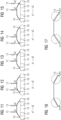
- the different sections of the trapezoid are given value ranges 14, 15, 16, 17, 18, which make a statement about the accuracy of the stopping point.
- both sensors 12, 13 determine a measured value in the value range 14, which means that the stopping point is adhered to very precisely and no correction of the vehicle braking curve is required.
- the doors 2 of the vehicle 1 and the platform doors 8 can be opened when the vehicle is stationary. If both sensors 12, 13 are in the value range 14, the vehicle 1 has reached the stopping point very precisely, so that the doors 2 of the vehicle 1 may be opened and a correction or calibration of the braking curve of the vehicle 1 is not required.
- figure 12 shows a second embodiment for a distance measurement by means of a first and a second sensor 12, 13 and a distance profile 10 in trapezoidal shape.
- the first sensor 12 is in the value range 15 and the second sensor in the value range 14. This means that the stopping point is still sufficiently precise so that the doors 2 of the vehicle 1 may be opened when the vehicle 1 is stationary.
- the braking curve of the vehicle 1 should be corrected or calibrated so that the vehicle 1 brakes later and/or more weakly in the future and thus continues to drive, so that a position is reached in which both sensors 12, 13 achieve a measured value in the value range 14 .
- figure 13 shows a third embodiment for a distance measurement by means of a first and a second sensor 12, 13 and a distance profile 10 in trapezoidal shape.
- the second sensor 13 is in the value range 16 and the first sensor in the value range 14.
- the stopping point is still sufficiently precise so that the doors 2 of the vehicle 1 may be opened when the vehicle 1 is stationary.
- the braking curve of the vehicle 1 should be corrected or calibrated so that the vehicle 1 brakes earlier and/or more heavily in the future and thus travels less far so that it reaches a position is, in which both sensors 12, 13 achieve a measured value in the value range 14. If one of sensors 12, 13 is in value range 15 or 16 and the other sensor 12, 13 is in value range 14, vehicle 1 has reached the stopping point with sufficient accuracy, but the braking curve of vehicle 1 must be corrected or calibrated .
- figure 14 shows a fourth embodiment for a distance measurement by means of a first and a second sensor 12, 13 and a distance profile 10 in trapezoidal shape.
- the vehicle 1 has reached the stopping point far too early, so that the first sensor 12 is in the value range 17 and the second sensor is in the value range 14 .
- the stopping point has no longer been reached with sufficient accuracy, so that the vehicle is not allowed to open the doors 2 in this position.
- the vehicle must therefore change its position in such a way that at least one sensor 12, 13 is in the value range 14 and the other sensor 12, 13 is in the value range 15 or 16 so that the doors 2 of the vehicle 1 may be opened.
- the braking curve of the vehicle 1 must be corrected or calibrated so that the vehicle 1 brakes later and/or more weakly in the future and thus continues to drive, so that a position is reached in which the first sensor 12 is not assigned a measured value in the value range 17 .
- figure 15 shows a fifth embodiment for a distance measurement by means of a first and a second sensor 12, 13 and a distance profile 10 in trapezoidal shape.
- vehicle 1 has reached the stopping point far too late, so that first sensor 12 is in value range 14 and second sensor is in value range 18 .
- the stopping point has no longer been reached with sufficient accuracy, so that the vehicle 1 is not allowed to open the doors 2 in this position.
- the vehicle 1 must therefore change its position in such a way that at least one sensor 12, 13 is in the value range 14 and the other sensor 12, 13 in the value range 15 or 16 so that the doors 2 of the vehicle 1 may be opened.
- the braking curve of the vehicle 1 must be corrected or calibrated so that the vehicle 1 will brake earlier and/or harder in the future and therefore drive less far, so that a position is reached in which the second sensor 13 does not assign a measured value in the value range 18 becomes. Therefore, if at least one sensor 12, 13 is in the value range 17 or 18, the vehicle 1 has no longer reached the stopping point with sufficient accuracy, so that the doors 2 of the vehicle 1 may not be opened and, in addition, a correction or calibration of the braking curve of the vehicle 1 is required.
- figure 16 shows a first exemplary embodiment of a spacer profile 10 in the form of a trapezium, in which the rising and the falling edge of the spacer profile 10 designed as a trapezium have a straight course.
- a spacer profile 10 is easy to manufacture.
- the straight course could occasionally result in the sensor of the sensor unit provided for detecting the distance not being able to carry out a detection correctly due to the smooth surface.
- figure 17 shows a second exemplary embodiment of a spacer profile 10 in the form of a trapezoid, in which the rising and the falling edge of the spacer profile 10 designed as a trapezoid have a stepped profile.
- a spacer profile 10 in the form of a trapezoid, in which the rising and the falling edge of the spacer profile 10 designed as a trapezoid have a stepped profile.
- the system according to the invention therefore carries out an evaluation using analog measured values recorded by measuring the distance from sensors 12, 13, thereby reliably recording the absolute stopping point accuracy achieved during operation and optimizing the stopping point accuracy made possible by automated correction of the braking curve.
Landscapes
- Engineering & Computer Science (AREA)
- Mechanical Engineering (AREA)
- Train Traffic Observation, Control, And Security (AREA)
- Length Measuring Devices With Unspecified Measuring Means (AREA)
- Control Of Position, Course, Altitude, Or Attitude Of Moving Bodies (AREA)
Description
- Die vorliegende Erfindung betrifft ein System zur Erfassung und Optimierung der Haltepunktgenauigkeit eines Fahrzeugs.
- Beim Betrieb von schienengebundenen Verkehrssystemen erfolgt eine zunehmende Automatisierung, was beispielsweise am Einsatz von fahrerlosen Systemen bei Metros oder U-Bahnen erkennbar ist. Im Zuge dieser Automatisierung, insbesondere im Bereich der Nahverkehrssysteme, ist auch ein Schutz der Fahrgäste am Bahnsteig erforderlich. Hierzu werden unter anderem Bahnsteigtüren eingesetzt, welche in oft aus Glas bestehenden Wänden, die die Plattform eines Haltepunktes vom Bereich des Schienen umfassenden Gleises trennen, integriert sind. Auf diese Weise wird ein Sturz von Personen in den Fahrweg beziehungsweise in das Gleis verhindert. Der Einsatz einer derartigen Schutzmaßnahme bedingt jedoch, dass bei einem Halt des Fahrzeuges die Fahrzeugtüren desselben möglichst genau in Deckung mit den Bahnsteigtüren gebracht werden müssen, da nur so ein zügiger und gefahrloser Fahrgastwechsel stattfinden kann.
- Die dafür angestrebte Haltepunktgenauigkeit lässt derzeit Abweichungen von circa 10 cm bis circa 30 cm zu. Werden die Fahrzeugtüren mit den Bahnsteigtüren nicht ausreichend in Deckung gebracht, so verengt sich der Durchgang für den Fahrgastwechsel und es kann dadurch zu einem Gedränge unter den Fahrgästen bis hin zu einer Panikreaktion bei denselben kommen. Infolgedessen kann es zu verletzten oder sogar möglicherweise getöteten Personen kommen.
- Die
WO 2016/035597 A1 und dieUS 2017/305396 A1 beschreiben ein automatisches Zugsteuersystem und eine Bremssteuerungsvorrichtung. DieDE 10 2012 219901 A1 beschreibt ein Verfahren zur Erhöhung der Haltegenauigkeit eines bewegten Objekts. Es besteht daher die Aufgabe, eine verbesserte Erfassung der im Betrieb eines schienengebundenen Fahrzeugs erreichten Haltepunktgenauigkeit beziehungsweise der hinsichtlich der Haltepunktgenauigkeit auftretenden Abweichungen bereitzustellen und dadurch eine Optimierung der Haltepunktgenauigkeit durch eine automatisierte Korrektur der Bremskurve eines Fahrzeuges zu ermöglichen. Dadurch soll sicherungstechnisch eine Haltepunktgenauigkeit von 10 cm oder weniger realisiert werden können. - Erfindungsgemäß wird eine Vorrichtung zur Erfassung und Optimierung der Haltepunktgenauigkeit eines Fahrzeugs gemäß Patentanspruch 1 zur Verfügung gestellt, umfassend wenigstens eine an dem Fahrzeug anordenbare Sensoreinheit und wenigstens eine mit der wenigstens einen Sensoreinheit verbundene Auswerteeinheit. Die wenigstens eine Sensoreinheit ist zur Messung eines Abstands relativ zu einem an einem von dem Fahrzeug befahrenen Haltepunkt angeordneten Abstandsprofil sowie zur Übermittlung des Messergebnisses an die wenigstens eine mit der Sensoreinheit verbundene Auswerteeinheit ausgebildet.
- Erfindungsgemäß wird ein System zur Erfassung und Optimierung der Haltepunktgenauigkeit eines Fahrzeugs gemäß Patentanspruch 2 zur Verfügung gestellt, welches wenigstens eine an dem Fahrzeug angeordnete Sensoreinheit, wenigstens ein an einem von dem Fahrzeug befahrenen Haltepunkt angeordnetes Abstandsprofil und wenigstens eine mit der wenigstens einen Sensoreinheit verbundene Auswerteeinheit umfasst. Erfindungsgemäß ist die wenigstens eine Sensoreinheit zur Messung des Abstandes zu dem wenigstens einen Abstandsprofil und zur Übermittlung des Messergebnisses an die wenigstens eine mit der Sensoreinheit verbundene Auswerteeinheit ausgebildet.
- Die erfindungsgemäße Lösung hat den Vorteil, dass durch eine Auswertung von analogen Messwerten, welche aus einer Messung des Abstandes von einer Sensoreinheit zu einem streckenseitig montierten, korrespondierenden Abstandsprofil resultieren, eine signaltechnisch sichere Erfassung der im Betrieb erreichten absoluten Haltepunktgenauigkeit erfolgen kann.
- Dadurch wird es zudem ermöglicht, eine Optimierung der Haltepunktgenauigkeit durch automatisierte Korrektur der Bremskurve für das Fahrzeug durchzuführen.
- Mittels eines derartigen durch das erfindungsgemäße System ermöglichten automatisierten Anlernens des Haltepunktes reduzieren sich des Weiteren dynamische Tests bei Inbetriebnahmen. Die Erfindung bietet zudem Vorteile bei der Ortssynchronisation beziehungsweise bei der Wegerfassung für ein Fahrzeug, da zum Beispiel ein sich über die Zeit reduzierender Raddurchmesser des Fahrzeugs aufgrund einer veränderten Haltepunktgenauigkeit erkannt und automatisch durch Anpassung der Bremskurve für das Fahrzeug ausgeglichen werden kann.
- Gemäß einer vorteilhaften Ausgestaltung des erfindungsgemäßen Systems ist vorgesehen, dass die wenigstens eine an dem Fahrzeug angeordnete Sensoreinheit zwei Sensoren zur Abstandsmessung umfasst. Derartige für eine Abstandsmessung vorgesehene Sensoren sind in der Lage, Objekte aus unterschiedlichen Materialien wie Metall, Holz oder Kunststoff zu erfassen. Zudem beeinträchtigen Umwelteinflüsse wie Feuchte, Staub und Rauch ihre Messgenauigkeit nicht. Des Weiteren führen auch Niederschläge wie Regen oder Schnee in normaler Dichte zu keiner Funktionsbeeinträchtigung der Sensoren, so dass auch ein Einsatz an oberirdisch gelegenen Haltepunkten möglich ist. Weiterhin ist optional durch konstruktive Maßnahmen ein vor Umwelteinflüssen geschützter Einbau möglich.
- Vorteilhafterweise ist weiter eine Anordnung der wenigstens einen Sensoreinheit unterhalb einer Tür des Fahrzeugs vorgesehen. Dadurch wird es insbesondere bei Haltepunkten, welche einen ebenerdigen Ein- und Ausstieg aufweisen, ermöglicht, die unterhalb der Tür angeordnete Sensoreinheit auf gleicher Höhe mit dem am Bahnsteig des Haltepunktes befestigten, korrespondierenden Abstandsprofil anzuordnen.
- Erfindungsgemäß ist eine Anordnung der wenigstens einen Sensoreinheit an der Unterseite des Fahrzeugs und eine Anordnung des wenigstens einen Abstandsprofils im Gleis vorgesehen. Dadurch wird eine Redundanz und eine aus dieser resultierende erhöhte Sicherheit bei der Erfassung der Haltepunktgenauigkeit eines Fahrzeugs erzielt. Vorteilhafterweise kann zudem vorgesehen sein, dass eine Validierung der von mehreren Sensoreinheiten erfassten Messergebnisse mittels einer Plausibilitätsprüfung erfolgt. Dadurch können defekte Sensoreinheiten erkannt werden.
- Besonders bevorzugt sind wenigstens zwei Sensoren zur Abstandsmessung sowie eine damit verbundene Auswerteeinheit am Fahrzeug vorgesehen. Dadurch wird erreicht, dass nicht nur eine Erfassung durchgeführt wird, ob das Fahrzeug am Haltepunkt zum Stehen gekommen ist oder den Haltepunkt verfehlt hat, sondern eine Ermittlung ermöglicht, inwieweit Abweichungen zum optimalen Haltepunkt gegeben sind.
- Vorteilhafterweise sind ferner je Seite des Fahrzeugs wenigstens zwei Auswerteeinheiten sowie damit verbundene Sensoreinheiten vorgesehen. Dadurch wird erfindungsgemäß eine signaltechnisch sichere Realisierung ermöglicht, welche eine Funktion des Systems auch bei einem Defekt einer der Auswerteeinheiten oder einer der Sensoreinheiten gewährleistet.
- Gemäß einer bevorzugten Ausgestaltung des erfindungsgemäßen Systems sind eine Auswerteeinheit sowie eine damit verbundene Sensoreinheit sowohl an der ersten Tür als auch an der letzten Tür je Seite des Fahrzeugs vorgesehen. Damit wird eine Plausibilitätsprüfung dahingehend möglich, ob das Fahrzeug vollständig, also über seine gesamte Länge, am Bahnsteig eines Haltepunktes steht. Weiterhin wird eine Plausibilitätsprüfung dahingehend möglich, auf welcher Seite sich der Bahnsteig befindet und ob somit die Türen zum Öffnen freigegeben werden dürfen.
- In einer weiteren bevorzugten Variante der Erfindung ist die wenigstens eine Auswerteeinheit in einem Zugsicherungsrechner des Fahrzeugs integriert. Dies hat den Vorteil, dass der Zugsicherungsrechner, beispielsweise ein Automatic Train Protection (ATP)-Gerät, eine Kommunikationsschnittstelle zu einer Einrichtung für die Zugsteuerung, beispielsweise ein Automatic Train Operation (ATO)-Gerät, aufweist und so die Möglichkeit besteht, die bezüglich der Haltepunktgenauigkeit notwendigen Korrekturwerte für die Bremskurve direkt vom Zugsicherungsrechner an die Zugsteuerung zu übergeben.
- Die wenigstens eine Auswerteeinheit des erfindungsgemäßen Systems weist vorteilhafterweise Mittel zur automatisierten Korrektur der Bremskurve des Fahrzeugs auf. Die Mittel können dabei als Mikroprozessor, beispielsweise im Rahmen einer integrierten Schaltung, vorliegen. Dadurch wird es ermöglicht, dass nicht nur eine Erfassung der Haltepunktgenauigkeit durchgeführt wird, sondern dass auch eine Optimierung diesbezüglich umgesetzt werden kann, indem die Bremskurve für das Fahrzeug unter Berücksichtigung der ermittelten Haltepunktgenauigkeit modifiziert wird.
- Vorteilhafterweise weist die wenigstens eine Auswerteeinheit ferner Mittel zur Übermittlung der Werte hinsichtlich der automatisierten Korrektur der Bremskurve des Fahrzeugs an eine Steuereinrichtung des Fahrzeugs auf. Die Mittel können dabei als drahtlose oder drahtgebundene Kommunikationsschnittstelle ausgebildet sein. Dies ist insbesondere für den Fall vorteilhaft, dass die Auswerteeinheit nicht im Zugsicherungsrechner integriert ist, da auf diese Weise dennoch eine automatisierte Optimierung der Bremskurve des Fahrzeugs durchgeführt werden kann.
- Gemäß einer weiteren bevorzugten Ausgestaltung der Erfindung weist das wenigstens eine Abstandsprofil die Form eines Rechtecks, eines Dreiecks oder eines Trapezes auf. Bei einem Abstandsprofil mit der Form eines Rechtecks wird eine Erfassung dahingehend ermöglicht, ob das Fahrzeug am Haltepunkt unter Berücksichtigung der zulässigen Abweichungen zum Stehen gekommen ist oder ob es den Haltepunkt verfehlt hat. Bei einem Abstandsprofil mit der Form eines Dreiecks wird es weiter ermöglicht, dass auch die Abweichungen zum optimalen Haltepunkt erfasst werden können. Ein Abstandsprofil mit der Form eines Trapezes ermöglicht es ferner, dass bei einem ausreichend genauen Haltepunkt des Fahrzeuges keine permanenten Korrekturen der Fahrzeugposition durchgeführt werden müssen. Vorzugsweise besteht das wenigstens eine Abstandsprofil aus einem insbesondere gebogenen Blech, einem Kunststoffkörper oder einem Beton-Formteil. Abstandsprofile aus derartigen Materialien sind einfach zu fertigen und sind dennoch für eine Abstandsmessung mittels der Sensoreinheit, insbesondere mittels einer zwei Ultraschallsensoren umfassenden Sensoreinheit, geeignet.
- In einer weiter bevorzugten Ausführung ist das wenigstens eine Abstandsprofil an seinen schräg verlaufenden Flächen gestuft ausgeführt. Diese Ausführung bietet Vorteile bei der Abstandsmessung durch die wenigstens eine Sensoreinheit, da mitunter Sensoren zur Abstandsmessung zum Einsatz kommen, welche glatte schräg stehende Flächen schlecht erfassen können.
- Ferner wird erfindungsgemäß ein Fahrzeug gemäß Anspruch 14 und ein Verfahren gemäß Anspruch 15 zur Verfügung gestellt.
- Die oben beschriebenen Eigenschaften, Merkmale und Vorteile dieser Erfindung sowie die Art und Weise, wie diese erreicht werden, werden klarer und deutlicher verständlich im Zusammenhang mit der folgenden Beschreibung der Ausführungsbeispiele, die im Zusammenhang mit den Zeichnungen näher erläutert werden. Es zeigen:
- Figur 1
- eine aus dem Stand der Technik bekannte Vorrichtung zur Erfassung der Haltepunktgenauigkeit eines Fahrzeugs,
- Figur 2
- ein in einer Seitenansicht dargestelltes Fahrzeug entsprechend dem erfindungsgemäßen System,
- Figur 3
- ein in einer Unteransicht dargestelltes Fahrzeug entsprechend dem erfindungsgemäßen System,
- Figur 4
- einen Haltepunkt entsprechend dem erfindungsgemäßen System,
- Figur 5
- ein erstes Ausführungsbeispiel für eine Abstandsmessung mittels eines ersten und eines zweiten Sensors und einem Abstandsprofil in rechteckiger Form,
- Figur 6
- ein zweites Ausführungsbeispiel für eine Abstandsmessung mittels eines ersten und eines zweiten Sensors und einem Abstandsprofil in rechteckiger Form,
- Figur 7
- ein drittes Ausführungsbeispiel für eine Abstandsmessung mittels eines ersten und eines zweiten Sensors und einem Abstandsprofil in rechteckiger Form,
- Figur 8
- ein erstes Ausführungsbeispiel für eine Abstandsmessung mittels eines ersten und eines zweiten Sensors und einem Abstandsprofil in dreieckiger Form,
- Figur 9
- ein zweites Ausführungsbeispiel für eine Abstandsmessung mittels eines ersten und eines zweiten Sensors und einem Abstandsprofil in dreieckiger Form,
- Figur 10
- ein drittes Ausführungsbeispiel für eine Abstandsmessung mittels eines ersten und eines zweiten Sensors und einem Abstandsprofil in dreieckiger Form,
- Figur 11
- ein erstes Ausführungsbeispiel für eine Abstandsmessung mittels eines ersten und eines zweiten Sensors und einem Abstandsprofil in Trapezform,
- Figur 12
- ein zweites Ausführungsbeispiel für eine Abstandsmessung mittels eines ersten und eines zweiten Sensors und einem Abstandsprofil in Trapezform,
- Figur 13
- ein drittes Ausführungsbeispiel für eine Abstandsmessung mittels eines ersten und eines zweiten Sensors und einem Abstandsprofil in Trapezform,
- Figur 14
- ein viertes Ausführungsbeispiel für eine Abstandsmessung mittels eines ersten und eines zweiten Sensors und einem Abstandsprofil in Trapezform,
- Figur 15
- ein fünftes Ausführungsbeispiel für eine Abstandsmessung mittels eines ersten und eines zweiten Sensors und einem Abstandsprofil in Trapezform,
- Figur 16
- ein erstes Ausführungsbeispiel eines Abstandsprofils in Trapezform,
- Figur 17
- ein zweites Ausführungsbeispiel eines Abstandsprofils in Trapezform.
- Im Folgenden wird die erfindungsgemäße Vorrichtung zur Erfassung der Haltepunktgenauigkeit eines Fahrzeugs 1 erläutert werden. Das erfindungsgemäße Fahrzeug 1 ist dabei, wie beispielhaft in den Figuren gezeigt, bevorzugt aber nicht beschränkend, ein schienengebundenes Fahrzeug 1, welches sich auf einem Schienen 20 umfassenden Gleis 19 fortbewegt.
- In der
Figur 1 ist eine aus dem Stand der Technik bekannte Vorrichtung zur Erfassung der Haltepunktgenauigkeit eines Fahrzeugs 1 gezeigt, bei welcher an einem Fahrzeug 1 zwei Wegimpulsgeber 3, zwei Radargeräte 4 sowie zwei Balisenantennen 5 vorgesehen sind. Das Fahrzeug 1 ist vorzugsweise ein schienengebundenes Fahrzeug 1, welches sich auf Schienen 20 fortbewegt, die Bestandteil eines Gleises 19 sind. Dabei wird mit dem punktförmigen Balisen-Übertragungskanal, welcher zwischen der Balisenantenne 5 des Fahrzeugs 1 und der streckenseitigen, vorzugsweise im Gleis 19 angeordneten, Festdaten-Balise 6 gebildet wird, eine Ortssynchronisation realisiert. Ferner wird mittels der Wegimpulsgeber 3 die zurückgelegte Wegstrecke über den bekannten Radumfang berechnet. Über einen Bremseingriff wird das Fahrzeug 1 bis zum Haltepunkt zum Stehen gebracht. Für die Berechnung der Haltepunktgenauigkeit spielen die möglichen Abweichungen der Balisenmittenerkennung für die Ortssynchronisation, eine fehlerhafte Wegstrecke durch ein mögliches Gleiten der Räder beim Bremsvorgang und Ungenauigkeiten beim Radumfang eine wichtige Rolle. Sicherungstechnisch lassen sich daher bisher nur Haltegenauigkeiten bis circa 1 m realisieren. Eine Erfassung der im Betrieb erreichten absoluten Haltepunktgenauigkeiten beziehungsweise die im Rahmen dieser auftretenden Abweichungen erfolgt zudem nicht. Des Weiteren ist auch keine Optimierung auf den Haltepunkt durch automatisierte Korrektur der Bremskurve des Fahrzeugs möglich. Selbst bei Nutzung von zusätzlichen Radar-Sensoren für die Berechnung der Wegstrecke sind Sensorschwächen der Radar-Sensoren zu berücksichtigen, weshalb auch dabei kein zufriedenstellendes Resultat hinsichtlich der Haltepunktgenauigkeit erzielbar ist. -
Figur 2 zeigt ein in einer Seitenansicht dargestelltes schienengebundenes Fahrzeug 1, mit welchem ein Schienen 20 umfassendes Gleis 19 befahrbar ist, entsprechend dem erfindungsgemäßen System, umfassend jeweils eine unterhalb der beiden äu-ßeren Türen 2 angeordnete Sensoreinheit 7, welche jeweils mit einer Auswerteeinheit 11 verbunden ist. Die für die Erfassung der absoluten Haltepunktgenauigkeit am Fahrzeug 1 angebrachten Sensoreinheiten 7 sind zur Abstandsmessung erforderlich und können beispielsweise Ultraschallsensoren umfassen. Zwei Balisen 5, zwei Wegimpulsgeber 3 und zwei Radargeräte 4 können vorliegend für eine Grob-Ortung des Fahrzeugs 1 und die eigentlichen Funktionen der Zugsicherung erhalten bleiben. - In
Figur 3 ist das schienengebundene Fahrzeug 1 in einer Unteransicht dargestellt, wodurch erkennbar wird, dass die Sensoreinheiten 7 auf beiden Seiten des Fahrzeugs 1 jeweils im Bereich der beiden äußeren Türen angeordnet sind. -
Figur 4 zeigt ferner einen entsprechend der vorliegenden Erfindung ausgestatteten Haltepunkt, welcher einen Bahnsteig umfasst, der auf Bahnsteigseite unterhalb der Plattformtüren und auf gleicher Höhe der Sensoreinheiten 7 des Fahrzeugs 1 Abstandsprofile 10 aufweist. Die Abstandsprofile sind dabei derart angeordnet, dass sie von den an den beiden äußeren Türen 2 des Fahrzeugs 1 angeordneten Sensoreinheiten 7 erfassbar sind. Ferner sind inFigur 4 acht Türen 8 am Haltepunkt zu erkennen, welche in eine Umgebungswand 9, die bevorzugt aus Glas ist, am Haltepunkt integriert sind und durch welche Fahrgästen der Einstieg in das Fahrzeug 1 ermöglicht wird. Jeweils zwei der Sensoreinheiten 7, welche einer Tür 2 zugeordnet sind, liefern einer Auswerteeinheit 11 zwei unabhängige Analogwerte, beispielsweise Spannungs- und/oder Stromwert, zur Auswertung und zur Ermittlung des Abstands a1, a2 zwischen einer Sensoreinheit und einem Abstandsprofil 10. Die Höhe des Ausgangswertes ist dabei proportional zum Abstand a1, a2. Vorliegend sind je Seite des Fahrzeugs 1 zwei Auswerteeinheiten 11 für eine signaltechnisch sichere Realisierung erforderlich. - Nachfolgend werden das Abstandsprofil 10 und die beiden Sensoren 12, 13, welche die Erfassung der im Betrieb erreichten absoluten Haltepunktgenauigkeit und die Optimierung auf den Haltepunkt ermöglichen, beschrieben.
-
Figur 5 zeigt ein erstes Ausführungsbeispiel für eine Abstandsmessung mittels eines ersten und eines zweiten Sensors 12, 13 und einem Abstandsprofil 10 in rechteckiger Form. Die Form eines Rechtecks für das Abstandsprofil 10 ermöglicht lediglich die Erfassung, ob das Fahrzeug 1 am Haltepunkt zum Stehen gekommen ist oder ob es den Haltepunkt verfehlt hat. InFigur 5 ist erkennbar, dass beide Sensoren 12, 13 den hervorstehenden Bereich des Abstandsprofils 10 erfassen. Daraus resultiert, dass das Fahrzeug 1 derart am Haltepunkt zum Stillstand gekommen ist, dass das im Bereich einer Tür 8 am Haltepunkt angeordnete Abstandsprofil 10 den beiden im Bereich der Tür 2 des Fahrzeugs 1 angeordneten Sensoren 12, 13 gegenüberliegt, woraus zwei gleich große Abstände a1, a2 zwischen dem hervorstehenden Bereich des Abstandsprofils 10 und den Sensoren 12, 13 resultieren. Der Haltepunkt wurde demnach optimal getroffen. -
Figur 6 zeigt ein zweites Ausführungsbeispiel für eine Abstandsmessung mittels eines ersten und eines zweiten Sensors 12, 13 und einem Abstandsprofil 10 in rechteckiger Form, bei welchem das Fahrzeug 1 den Haltepunkt zu früh erreicht hat, also zu früh zum Stillstand gekommen ist. Der erste Sensor 12 weist im Vergleich zum zweiten Sensor 13 einen größeren Abstand a1 zum Abstandsprofil 10 auf. Lediglich der Abstand a2 von dem zweiten Sensor 13 zum Abstandsprofil 10 weist den gewünschten Wert auf. -
Figur 7 zeigt ein drittes Ausführungsbeispiel für eine Abstandsmessung mittels eines ersten und eines zweiten Sensors 12, 13 und einem Abstandsprofil 10 in rechteckiger Form, bei welchem das Fahrzeug 1 den Haltepunkt zu spät erreicht hat, also zu spät zum Stillstand gekommen ist. Hier weist der zweite Sensor 13 im Vergleich zum ersten Sensor 12 einen größeren Abstand a2 zum Abstandsprofil 10 auf. Der Abstand a1 von dem ersten Sensor 12 zum Abstandsprofil 10 weist hingegen den gewünschten Wert auf. -
Figur 8 zeigt ein erstes Ausführungsbeispiel für eine Abstandsmessung mittels eines ersten und eines zweiten Sensors 12, 13 und einem Abstandsprofil 10 in dreieckiger Form. Durch die dreieckige Form wird auch die Erfassung von Abweichungen zum optimalen Haltepunkt ermöglicht. Bei dem inFigur 8 dargestellten Ausführungsbeispiel wurde der Haltepunkt vom Fahrzeug 1 optimal getroffen, das heißt das Fahrzeug 1 ist weder zu früh noch zu spät zum Stillstand gekommen. Ein derartiger Fall, bei welchem der Abstand zwischen dem ersten Sensor und dem Abstandsprofil 10 sowie dem zweiten Sensor und dem Abstandsprofil 10 mit a1=a2 exakt übereinstimmt, wird in der Realität nicht auftreten, da kleine Differenzen zwischen a1 und a2 nicht auszuschließen sind. -
Figur 9 zeigt ein zweites Ausführungsbeispiel für eine Abstandsmessung mittels eines ersten und eines zweiten Sensors 12, 13 und einem Abstandsprofil 10 in dreieckiger Form, bei welchem der Haltepunkt zu früh erreicht wurde, das Fahrzeug also zu früh zum Stillstand gekommen ist. Der Abstand a1 des ersten Sensors 12 zum Abstandsprofil 10 ist größer als der Abstand a2 des zweiten Sensors 13 zum Abstandsprofil 10. Vorliegend sollte eine Korrektur der Bremskurve des Fahrzeugs 1 durchgeführt werden, indem die Bremskurve dahingehend modifiziert wird, dass das Fahrzeug 1 später und/oder schwächer bremst und dadurch weiter fährt, so dass eine Position erreicht wird, in welcher die beiden Abstände a1 und a2 der Sensoren 12, 13 vom Abstandsprofil 10 nahezu übereinstimmen. -
Figur 10 zeigt ein drittes Ausführungsbeispiel für eine Abstandsmessung mittels eines ersten und eines zweiten Sensors 12, 13 und einem Abstandsprofil 10 in dreieckiger Form, bei welchem der Haltepunkt zu spät erreicht wurde, das Fahrzeug also zu spät zum Stillstand gekommen ist. Der Abstand a2 des zweiten Sensors 13 zum Abstandsprofil 10 ist größer als der Abstand a1 des ersten Sensors 12 zum Abstandsprofil 10. Vorliegend sollte eine Korrektur der Bremskurve des Fahrzeugs 1 durchgeführt werden, indem die Bremskurve dahingehend modifiziert wird, dass das Fahrzeug 1 früher und/oder stärker bremst und dadurch weniger weit fährt, so dass eine Position erreicht wird, in welcher die beiden Abstände a1 und a2 der Sensoren 12, 13 vom Abstandsprofil 10 nahezu übereinstimmen. -
Figur 11 zeigt ein erstes Ausführungsbeispiel für eine Abstandsmessung mittels eines ersten und eines zweiten Sensors 12, 13 und einem Abstandsprofil 10 in Trapezform. Um zu verhindern, dass bei einem ausreichend genauen Haltepunkt nicht permanent Korrekturen der Bremskurve des Fahrzeugs 1 durchgeführt werden müssen, da die von den beiden Sensoren 12, 13 gemessenen Abstände a1, a2 nicht übereinstimmen, wird ein Abstandsprofil in Trapezform verwendet. Bei dieser Form werden den verschieden Abschnitten des Trapezes Wertebereiche 14, 15, 16, 17, 18 zugeordnet, welche eine Aussage über die Genauigkeit des Haltepunkts machen. InFigur 11 ermitteln beide Sensoren 12, 13 einen Messwert im Wertebereich 14, woraus resultiert, dass der Haltepunkt sehr genau eingehalten und keine Korrektur der Fahrzeug-Bremskurve erforderlich wird. Die Türen 2 des Fahrzeugs 1 und die Plattformtüren 8 können bei stehendem Fahrzeug geöffnet werden. Sofern daher beide Sensoren 12, 13 im Wertebereich 14 liegen, ist der Haltepunkt vom Fahrzeug 1 sehr genau erreicht worden, so dass die Türen 2 des Fahrzeugs 1 geöffnet werden dürfen und eine Korrektur beziehungsweise Kalibrierung der Bremskurve des Fahrzeugs 1 nicht erforderlich ist. -
Figur 12 zeigt ein zweites Ausführungsbeispiel für eine Abstandsmessung mittels eines ersten und eines zweiten Sensors 12, 13 und einem Abstandsprofil 10 in Trapezform. Dabei liegt der erste Sensor 12 im Wertebereich 15 und der zweite Sensor im Wertebereich 14. Dies bedeutet, dass der Haltepunkt noch ausreichend genau ist, so dass eine Öffnung der Türen 2 des Fahrzeugs 1 bei Stillstand des Fahrzeugs 1 erfolgen darf. Jedoch sollte eine Korrektur beziehungsweise Kalibrierung der Bremskurve des Fahrzeugs 1 vorgenommen werden, damit das Fahrzeug 1 zukünftig später und/oder schwächer bremst und dadurch weiter fährt, so dass eine Position erreicht wird, in welcher beide Sensoren 12, 13 einen Messwert im Wertebereich 14 erzielen. -
Figur 13 zeigt ein drittes Ausführungsbeispiel für eine Abstandsmessung mittels eines ersten und eines zweiten Sensors 12, 13 und einem Abstandsprofil 10 in Trapezform. Dabei liegt der zweite Sensor 13 im Wertebereich 16 und der erste Sensor im Wertebereich 14. Dies bedeutet, dass der Haltepunkt noch ausreichend genau ist, so dass eine Öffnung der Türen 2 des Fahrzeugs 1 bei Stillstand des Fahrzeugs 1 erfolgen darf. Jedoch sollte eine Korrektur beziehungsweise Kalibrierung der Bremskurve des Fahrzeugs 1 vorgenommen werden, damit das Fahrzeug 1 zukünftig früher und/oder stärker bremst und dadurch weniger weit fährt, so dass eine Position erreicht wird, in welcher beide Sensoren 12, 13 einen Messwert im Wertebereich 14 erzielen. Sofern daher einer der Sensoren 12, 13 im Wertebereich 15 oder 16 und der andere Sensor 12, 13 im Wertebereich 14 liegt, ist der Haltepunkt vom Fahrzeug 1 zwar noch ausreichend genau erreicht worden, aber eine Korrektur beziehungsweise Kalibrierung der Bremskurve des Fahrzeugs 1 ist vorzunehmen. -
Figur 14 zeigt ein viertes Ausführungsbeispiel für eine Abstandsmessung mittels eines ersten und eines zweiten Sensors 12, 13 und einem Abstandsprofil 10 in Trapezform. In diesem Ausführungsbeispiel hat das Fahrzeug 1 den Haltepunkt viel zu früh erreicht, so dass der erste Sensor 12 im Wertebereich 17 und der zweite Sensor im Wertebereich 14 liegt. Der Haltepunkt ist vorliegend nicht mehr ausreichend genau erreicht worden, so dass das Fahrzeug in dieser Position die Türen 2 nicht öffnen darf. Das Fahrzeug muss seine Position daher derart verändern, dass wenigstens ein Sensor 12, 13 im Wertebereich 14 und der andere Sensor 12, 13 im Wertebereich 15 oder 16 liegt, damit die Türen 2 des Fahrzeugs 1 geöffnet werden dürfen. Zudem muss eine Korrektur beziehungsweise Kalibrierung der Bremskurve des Fahrzeugs 1 vorgenommen werden, damit das Fahrzeug 1 zukünftig später und/oder schwächer bremst und dadurch weiter fährt, so dass eine Position erreicht wird, in welcher der erste Sensor 12 kein Messwert im Wertebereich 17 zugeordnet wird. -
Figur 15 zeigt ein fünftes Ausführungsbeispiel für eine Abstandsmessung mittels eines ersten und eines zweiten Sensors 12, 13 und einem Abstandsprofil 10 in Trapezform. In diesem Ausführungsbeispiel hat das Fahrzeug 1 den Haltepunkt viel zu spät erreicht, so dass der erste Sensor 12 im Wertebereich 14 und der zweite Sensor im Wertebereich 18 liegt. Der Haltepunkt ist vorliegend nicht mehr ausreichend genau erreicht worden, so dass das Fahrzeug 1 in dieser Position die Türen 2 nicht öffnen darf. Das Fahrzeug 1 muss seine Position daher derart verändern, dass wenigstens ein Sensor 12, 13 im Wertebereich 14 und der andere Sensor 12, 13 im Wertebereich 15 oder 16 liegt, damit die Türen 2 des Fahrzeugs 1 geöffnet werden dürfen. Zudem muss eine Korrektur beziehungsweise Kalibrierung der Bremskurve des Fahrzeugs 1 vorgenommen werden, damit das Fahrzeug 1 zukünftig früher und/oder stärker bremst und dadurch weniger weit fährt, so dass eine Position erreicht wird, in welcher der zweite Sensor 13 kein Messwert im Wertebereich 18 zugeordnet wird. Sofern daher wenigstens ein Sensor12, 13 im Wertebereich 17 oder 18 liegt, ist der Haltepunkt vom Fahrzeug 1 nicht mehr ausreichend genau erreicht worden, so dass die Türen 2 des Fahrzeugs 1 nicht geöffnet werden dürfen und zudem eine Korrektur beziehungsweise Kalibrierung der Bremskurve des Fahrzeugs 1 erforderlich ist. -
Figur 16 zeigt ein erstes Ausführungsbeispiel eines Abstandsprofils 10 in Trapezform, bei welchem die steigende und die fallende Flanke des als Trapez ausgebildeten Abstandsprofils 10 einen geraden Verlauf aufweisen. Ein derartiger Verlauf hat den Vorteil, dass das Abstandsprofil 10 einfach zu fertigen ist. Der gerade Verlauf könnte jedoch mitunter dazu führen, dass der Sensor der für die Erfassung des Abstandes vorgesehen Sensoreinheit eine Erfassung aufgrund der glatten Oberfläche nicht fehlerfrei durchführen kann. -
Figur 17 zeigt ein zweites Ausführungsbeispiel eines Abstandsprofils 10 in Trapezform, bei welchem die steigende und die fallende Flanke des als Trapez ausgebildeten Abstandsprofils 10 einen stufenförmigen Verlauf aufweisen. Ein derartiger Verlauf hat den Vorteil, dass auch kostengünstigere Sensoren der Sensoreinheit, welche mitunter Probleme mit der Erfassung von glatten schräg stehenden Flächen haben, eingesetzt werden können. - Durch das erfindungsgemäße System wird demnach eine Auswertung durch mittels Abstandsmessung von Sensoren 12, 13 erfassten analogen Messwerten durchgeführt, wodurch eine signaltechnisch sichere Erfassung der im Betrieb erreichten absoluten Haltepunktgenauigkeit und eine Optimierung der Haltepunktgenauigkeit durch automatisierte Korrektur der Bremskurve ermöglicht wird.
- Obwohl die Erfindung im Detail durch bevorzugte Ausführungsbeispiele näher illustriert und beschrieben wurde, so ist die Erfindung nicht durch die offenbarten Beispiele eingeschränkt und andere Variationen können vom Fachmann hieraus abgeleitet werden, ohne den Schutzumfang der Erfindung, der durch die Ansprüche definiert wird, zu verlassen.
Claims (15)
- Vorrichtung zur Erfassung und Optimierung der Haltepunktgenauigkeit eines Fahrzeugs (1), umfassend- wenigstens eine an dem Fahrzeug (1) anordenbare Sensoreinheit (7),- wenigstens eine mit der wenigstens einen Sensoreinheit (7) verbundene Auswerteeinheit (11),wobei die wenigstens eine Sensoreinheit (7) zur Messung eines Abstands zu einem an einem von dem Fahrzeug (1) befahrenen Haltepunkt angeordneten Abstandsprofil (10) und zur Übermittlung des Messergebnisses an die wenigstens eine mit der Sensoreinheit (7) verbundene Auswerteeinheit (11) ausgebildet ist,wobei das Fahrzeug (1) ein schienengebundenes Fahrzeug (1) ist und eine Anordnung der wenigstens einen Sensoreinheit (7) an der Unterseite des Fahrzeugs (1) anordenbar ist und eine Anordnung des wenigstens einen Abstandsprofils (10)- an einer vom Fahrzeug (1) befahrenen Schiene (20) oder im die Schiene (20) umgebenden Gleis (19) anordenbar ist, und dabei der vertikale Abstand zwischen Sensoreinheit (7) und Abstandsprofil (10) gemessen wird, oder- an einer sich am Haltepunkt befindlichen, das Fahrzeug (1) umgebenden Umgebungswand (9) anordenbar ist und dabei der horizontale Abstand zwischen Sensoreinheit (7) und Abstandsprofil (10) gemessen wird.
- System zur Erfassung und Optimierung der Haltepunktgenauigkeit eines Fahrzeugs (1), umfassend- wenigstens eine an dem Fahrzeug (1) angeordnete Sensoreinheit (7),- wenigstens ein an einem von dem Fahrzeug (1) befahrenen Haltepunkt angeordnetes Abstandsprofil (10),- wenigstens eine mit der wenigstens einen Sensoreinheit (7) verbundene Auswerteeinheit (11),wobei die wenigstens eine Sensoreinheit (7) zur Messung des Abstands zu dem wenigstens einen Abstandsprofil (10) und zur Übermittlung des Messergebnisses an die wenigstens eine mit der Sensoreinheit (7) verbundene Auswerteeinheit (11) ausgebildet ist,wobei das Fahrzeug (1) ein schienengebundenes Fahrzeug (1) ist und eine Anordnung der wenigstens einen Sensoreinheit (7) an der Unterseite des Fahrzeugs (1) und eine Anordnung des wenigstens einen Abstandsprofils (10)- an einer vom Fahrzeug (1) befahrenen Schiene (20), oder im die Schiene (20) umgebenden Gleis (19) vorgesehen ist, und dabei der vertikale Abstand zwischen Sensoreinheit (7) und Abstandsprofil (10) gemessen wird, oder- an einer sich am Haltepunkt befindlichen, das Fahrzeug (1) umgebenden Umgebungswand (9) vorgesehen ist und dabei der horizontale Abstand zwischen Sensoreinheit (7) und Abstandsprofil (10) gemessen wird.
- System nach Anspruch 2, wobei die wenigstens eine an dem Fahrzeug (1) angeordnete Sensoreinheit (7) wenigstens zwei Sensoren zur Abstandsmessung umfasst.
- System nach Anspruch 2 oder Anspruch 3, wobei eine Anordnung der wenigstens einen Sensoreinheit (7) unterhalb einer Tür (2) des Fahrzeugs (1) vorgesehen ist.
- System nach einem der Ansprüche 2 bis 3, wobei wenigstens zwei seitenselektiv angeordnete Auswerteeinheiten (11) sowie damit verbundene Sensoreinheiten (7) am Fahrzeug (1) vorgesehen sind.
- System nach Anspruch 5, wobei je Seite des Fahrzeugs (1) wenigstens zwei Auswerteeinheiten (11) sowie damit verbundene Sensoreinheiten (7) vorgesehen sind.
- System nach einem der Ansprüche 2 bis 6, wobei eine Auswerteeinheit (11) sowie eine damit verbundene Sensoreinheit (7) sowohl an der ersten Tür (2) als auch an der letzten Tür (2) je Seite des Fahrzeugs (1) vorgesehen sind.
- System nach einem der Ansprüche 2 bis 7, wobei das Fahrzeug (1) ein Zug ist und die wenigstens eine Auswerteeinheit (11) in einem Zugsicherungsrechner des Fahrzeugs (1) integriert ist.
- System nach einem der Ansprüche 2 bis 8, wobei die wenigstens eine Auswerteeinheit (11) Mittel zur automatisierten Korrektur der Bremskurve des Fahrzeugs (1) aufweist.
- System nach Anspruch 9, wobei die wenigstens eine Auswerteeinheit (11) ferner Mittel zur Übermittlung der Werte hinsichtlich der automatisierten Korrektur der Bremskurve des Fahrzeugs (1) an eine Steuereinrichtung des Fahrzeugs (1) aufweist.
- System nach einem der Ansprüche 2 bis 10, wobei das wenigstens eine Abstandsprofil (10) die Form eines Rechtecks, eines Dreiecks oder eines Trapezes aufweist.
- System nach einem der Ansprüche 2 bis 11, wobei das wenigstens eine Abstandsprofil (10) aus einem vorzugsweise gebogenen Blech, einem Kunststoffkörper oder einem Beton-Formteil besteht.
- System nach einem der Ansprüche 2 bis 12, wobei das wenigstens eine Abstandsprofil (10) an seinen schräg verlaufenden Flächen gestuft ausgeführt ist.
- Fahrzeug, insbesondere Schienenfahrzeug, mit einer Vorrichtung nach Anspruch 1.
- Verfahren zur Erfassung und Optimierung der Haltepunktgenauigkeit eines Fahrzeugs (1), wobei das Fahrzeug (1) ein schienengebundenes Fahrzeug (1) ist,bei dem wenigstens eine Sensoreinheit (7) an der Unterseite des Fahrzeugs (1) angeordnet wird,bei dem ein Abstand zu einem an einem von dem Fahrzeug (1) befahrenen Haltepunkt angeordneten Abstandsprofil (10) gemessen wird und das Messergebnisses von einer Sensoreinheit (7) an wenigstens eine verbundene Auswerteeinheit (11) übermittelt wird, undbei dem das wenigstens eine Abstandsprofils (10)- an einer vom Fahrzeug (1) befahrenen Schiene (20) oder im die Schiene (20) umgebenden Gleis (19) angeordnet wird, und der vertikale Abstand zwischen Sensoreinheit (7) und Abstandsprofil (10) gemessen wird, oder- an einer sich am Haltepunkt befindlichen, das Fahrzeug (1) umgebenden Umgebungswand (9) angeordnet wird und der horizontale Abstand zwischen Sensoreinheit (7) und Abstandsprofil (10) gemessen wird.
Applications Claiming Priority (2)
| Application Number | Priority Date | Filing Date | Title |
|---|---|---|---|
| DE102017216712.2A DE102017216712A1 (de) | 2017-09-21 | 2017-09-21 | Erfassung und Optimierung der Haltepunktgenauigkeit eines Fahrzeugs |
| PCT/EP2018/072523 WO2019057421A1 (de) | 2017-09-21 | 2018-08-21 | Erfassung und optimierung der haltepunktgenauigkeit eines fahrzeugs |
Publications (2)
| Publication Number | Publication Date |
|---|---|
| EP3658440A1 EP3658440A1 (de) | 2020-06-03 |
| EP3658440B1 true EP3658440B1 (de) | 2023-06-07 |
Family
ID=63528701
Family Applications (1)
| Application Number | Title | Priority Date | Filing Date |
|---|---|---|---|
| EP18766135.0A Active EP3658440B1 (de) | 2017-09-21 | 2018-08-21 | Erfassung und optimierung der haltepunktgenauigkeit eines fahrzeugs |
Country Status (7)
| Country | Link |
|---|---|
| US (1) | US11708100B2 (de) |
| EP (1) | EP3658440B1 (de) |
| CN (1) | CN111094104B (de) |
| DE (1) | DE102017216712A1 (de) |
| ES (1) | ES2953663T3 (de) |
| PL (1) | PL3658440T3 (de) |
| WO (1) | WO2019057421A1 (de) |
Families Citing this family (3)
| Publication number | Priority date | Publication date | Assignee | Title |
|---|---|---|---|---|
| DE102019207462A1 (de) * | 2019-05-22 | 2020-11-26 | Robert Bosch Gmbh | Verfahren zum Zielbremsen eines Fahrzeugs |
| CN112124365B (zh) * | 2020-09-18 | 2022-08-30 | 交控科技股份有限公司 | 城轨信号系统停车点定测方法以及系统 |
| WO2023108062A1 (en) * | 2021-12-08 | 2023-06-15 | Intramotev Inc. | Self-propelled railcar |
Family Cites Families (20)
| Publication number | Priority date | Publication date | Assignee | Title |
|---|---|---|---|---|
| JPS60488B2 (ja) | 1980-03-24 | 1985-01-08 | 不動建設株式会社 | 圧気効率を高めた粉粒状材料パイル造成工法 |
| JP2898846B2 (ja) * | 1993-05-24 | 1999-06-02 | 新日本製鐵株式会社 | 定位置停止制御装置 |
| SE515571C2 (sv) * | 2000-03-10 | 2001-09-03 | Daimler Chrysler Ag | Anordning och förfarande för att bestämma positionen för ett spårbundet fordon |
| GB0505452D0 (en) * | 2005-03-17 | 2005-04-20 | Aea Technology Plc | Door control system |
| DE102008050764A1 (de) | 2008-10-09 | 2010-04-22 | Siemens Aktiengesellschaft | Verfahren und Vorrichtung zur Erhöhung der Haltegenauigkeit eines bewegten Objektes |
| DE102008060188A1 (de) * | 2008-11-28 | 2010-06-10 | Siemens Aktiengesellschaft | Verfahren und Vorrichtung zur Abstandsmessung |
| FR2951683B1 (fr) * | 2009-10-27 | 2012-01-13 | Faiveley Transport | Systeme et procede de detection d'un quai et vehicule ferroviaire equipe d'un tel systeme |
| CN102167064A (zh) | 2011-04-08 | 2011-08-31 | 南京工程学院 | Rfid辅助的地铁列车位置检测及精确停车系统 |
| CN202022221U (zh) | 2011-04-08 | 2011-11-02 | 南京工程学院 | Rfid辅助的地铁列车位置检测及精确停车系统 |
| DE102011088891A1 (de) * | 2011-12-16 | 2013-06-20 | Siemens Aktiengesellschaft | Verfahren und Vorrichtung zur Erhöhung der Haltegenauigkeit eines bewegten Objektes |
| DE102012214724A1 (de) * | 2012-08-20 | 2014-02-20 | Siemens Aktiengesellschaft | Verfahren zur Erhöhung der Positionsgenauigkeit eines bewegten Objekts |
| DE102012219901A1 (de) * | 2012-10-31 | 2014-04-30 | Siemens Aktiengesellschaft | Verfahren und Vorrichtung zur Erhöhung der Haltegenauigkeit eines bewegten Objektes |
| JP6091294B2 (ja) * | 2013-04-02 | 2017-03-08 | 株式会社神戸製鋼所 | 列車先頭位置の検出方法及び検出装置 |
| NO3012398T3 (de) * | 2013-09-30 | 2018-04-28 | ||
| KR101860245B1 (ko) | 2014-01-30 | 2018-05-21 | 닛산 지도우샤 가부시키가이샤 | 주차 지원 장치 및 주차 지원 방법 |
| WO2016035597A1 (ja) * | 2014-09-05 | 2016-03-10 | 三菱電機株式会社 | 自動列車運行システム |
| DE102014221710A1 (de) * | 2014-10-24 | 2016-04-28 | Robert Bosch Gmbh | Verfahren zur Zielbremsung eines Schienenfahrzeugs |
| JP6000488B1 (ja) * | 2015-09-17 | 2016-09-28 | 三菱重工交通機器エンジニアリング株式会社 | 列車位置検知装置、列車停止検知装置、並びに列車位置検知方法及び列車停止検知方法 |
| RU2618569C1 (ru) * | 2015-12-28 | 2017-05-04 | Общество с ограниченной ответственностью "Инновационная компания ГМК" (ООО "Инновационная компания ГМК") | Способ и система для прицельного торможения подвижного состава |
| US10093331B2 (en) * | 2016-08-08 | 2018-10-09 | Mitsubishi Electric Research Laboratories, Inc. | Train automatic stopping control with quantized throttle and braking |
-
2017
- 2017-09-21 DE DE102017216712.2A patent/DE102017216712A1/de not_active Withdrawn
-
2018
- 2018-08-21 US US16/649,419 patent/US11708100B2/en active Active
- 2018-08-21 ES ES18766135T patent/ES2953663T3/es active Active
- 2018-08-21 WO PCT/EP2018/072523 patent/WO2019057421A1/de not_active Ceased
- 2018-08-21 CN CN201880060825.9A patent/CN111094104B/zh active Active
- 2018-08-21 PL PL18766135.0T patent/PL3658440T3/pl unknown
- 2018-08-21 EP EP18766135.0A patent/EP3658440B1/de active Active
Also Published As
| Publication number | Publication date |
|---|---|
| US20200283039A1 (en) | 2020-09-10 |
| ES2953663T3 (es) | 2023-11-15 |
| CN111094104B (zh) | 2022-09-16 |
| US11708100B2 (en) | 2023-07-25 |
| DE102017216712A1 (de) | 2019-03-21 |
| PL3658440T3 (pl) | 2023-10-16 |
| EP3658440A1 (de) | 2020-06-03 |
| CN111094104A (zh) | 2020-05-01 |
| WO2019057421A1 (de) | 2019-03-28 |
Similar Documents
| Publication | Publication Date | Title |
|---|---|---|
| EP2516305B1 (de) | Verfahren und vorrichtung zur bestimmung der bewegung und/oder der position einer aufzugskabine | |
| EP2386455B1 (de) | Schienenprüfvorrichtung | |
| DE102015208058B4 (de) | Automatisiertes Parksystem | |
| EP3079965B1 (de) | Verfahren und einrichtung zur erkennung einer entgleisung oder eines auftreffens eines hindernisses auf ein schienenfahrzeug | |
| EP3658440B1 (de) | Erfassung und optimierung der haltepunktgenauigkeit eines fahrzeugs | |
| DE102008050764A1 (de) | Verfahren und Vorrichtung zur Erhöhung der Haltegenauigkeit eines bewegten Objektes | |
| EP1575816A1 (de) | Messeinrichtung zum messen der rundheit eines eisenbahnrades | |
| DE102008012416A1 (de) | Verfahren zur signaltechnischen Sicherung schienengebundener Fahrzeuge und diesbezügliches Sicherungssystem | |
| EP2145809B1 (de) | Verfahren zum Ermitteln des Kupplungszustands einer Eisenbahnkupplung, Eisenbahnkupplung sowie Anordnung mit einer Eisenbahnkupplung | |
| WO2017220304A1 (de) | Verfahren zum betreiben einer ortungseinrichtung sowie ortungseinrichtung | |
| EP3319855B1 (de) | Anordnung und verfahren zur erzeugung eines türfreigabesignals für bahnsteigtüren | |
| EP0715579A1 (de) | Einrichtung zur freigabe des öffnens der türen von schienenfahrzeugen | |
| WO2009013114A1 (de) | Verfahren zur ermittlung der geschwindigkeit einer aufzugskabine und eine steuereinheit zur durchführung dieses verfahrens | |
| EP0568167B1 (de) | Verfahren zum Bestimmen des Rollwiderstandes von Eisenbahnfahrzeugen | |
| EP4079595B1 (de) | Einrichtung und verfahren zur positionsbestimmung für ein schienenfahrzeug | |
| EP1288155B1 (de) | Verfahren und Vorrichtung zur Ermittlung des Zustandes eines Schienenstranges | |
| EP2686222A1 (de) | Verfahren und einrichtung zum stellen einer elektrisch ortsgestellten weiche | |
| EP2038160A1 (de) | System und verfahren zur bestimmung der momentanen ortsposition von fahrzeugen, insbesondere von zügen | |
| WO2023285603A1 (de) | Verfahren zum sicheren betreiben eines schienenverkehrssystems und schienenverkehrssystem | |
| WO2016096824A1 (de) | Verfahren und system zur bestimmung der position und der orientierung einer aufzugskabine | |
| DE19907465A1 (de) | Vorrichtung zum Identifizieren von Objekten und Verwendungen der Vorrichtung | |
| EP2439123A2 (de) | Verfahren zur Ermittlung einer im Eisenbahngleis codierten Information | |
| DE102004012167B4 (de) | Verfahren zur Ermittlung des Raddurchmessers von Rädern von Schienenfahrzeugen, insbesondere von Güterwagen, sowie eine Schwerkraftablaufanlage unter Anwendung des Verfahrens | |
| EP3529122B1 (de) | Verfahren zum kalibrieren eines radsensors und entsprechender radsensor sowie eisenbahntechnische anlage mit einem solchen radsensor | |
| EP2130740B1 (de) | Steuereinrichtung für eine Ablaufanlage des schienengebundenen Verkehrs und Verfahren zum Betreiben einer solchen Anlage |
Legal Events
| Date | Code | Title | Description |
|---|---|---|---|
| STAA | Information on the status of an ep patent application or granted ep patent |
Free format text: STATUS: UNKNOWN |
|
| STAA | Information on the status of an ep patent application or granted ep patent |
Free format text: STATUS: THE INTERNATIONAL PUBLICATION HAS BEEN MADE |
|
| PUAI | Public reference made under article 153(3) epc to a published international application that has entered the european phase |
Free format text: ORIGINAL CODE: 0009012 |
|
| STAA | Information on the status of an ep patent application or granted ep patent |
Free format text: STATUS: REQUEST FOR EXAMINATION WAS MADE |
|
| 17P | Request for examination filed |
Effective date: 20200225 |
|
| AK | Designated contracting states |
Kind code of ref document: A1 Designated state(s): AL AT BE BG CH CY CZ DE DK EE ES FI FR GB GR HR HU IE IS IT LI LT LU LV MC MK MT NL NO PL PT RO RS SE SI SK SM TR |
|
| AX | Request for extension of the european patent |
Extension state: BA ME |
|
| DAV | Request for validation of the european patent (deleted) | ||
| DAX | Request for extension of the european patent (deleted) | ||
| GRAP | Despatch of communication of intention to grant a patent |
Free format text: ORIGINAL CODE: EPIDOSNIGR1 |
|
| STAA | Information on the status of an ep patent application or granted ep patent |
Free format text: STATUS: GRANT OF PATENT IS INTENDED |
|
| INTG | Intention to grant announced |
Effective date: 20221109 |
|
| GRAS | Grant fee paid |
Free format text: ORIGINAL CODE: EPIDOSNIGR3 |
|
| GRAA | (expected) grant |
Free format text: ORIGINAL CODE: 0009210 |
|
| STAA | Information on the status of an ep patent application or granted ep patent |
Free format text: STATUS: THE PATENT HAS BEEN GRANTED |
|
| AK | Designated contracting states |
Kind code of ref document: B1 Designated state(s): AL AT BE BG CH CY CZ DE DK EE ES FI FR GB GR HR HU IE IS IT LI LT LU LV MC MK MT NL NO PL PT RO RS SE SI SK SM TR |
|
| REG | Reference to a national code |
Ref country code: GB Ref legal event code: FG4D Free format text: NOT ENGLISH |
|
| REG | Reference to a national code |
Ref country code: CH Ref legal event code: EP Ref country code: AT Ref legal event code: REF Ref document number: 1574153 Country of ref document: AT Kind code of ref document: T Effective date: 20230615 Ref country code: DE Ref legal event code: R096 Ref document number: 502018012388 Country of ref document: DE |
|
| REG | Reference to a national code |
Ref country code: LT Ref legal event code: MG9D |
|
| REG | Reference to a national code |
Ref country code: NL Ref legal event code: MP Effective date: 20230607 |
|
| PG25 | Lapsed in a contracting state [announced via postgrant information from national office to epo] |
Ref country code: SE Free format text: LAPSE BECAUSE OF FAILURE TO SUBMIT A TRANSLATION OF THE DESCRIPTION OR TO PAY THE FEE WITHIN THE PRESCRIBED TIME-LIMIT Effective date: 20230607 Ref country code: NO Free format text: LAPSE BECAUSE OF FAILURE TO SUBMIT A TRANSLATION OF THE DESCRIPTION OR TO PAY THE FEE WITHIN THE PRESCRIBED TIME-LIMIT Effective date: 20230907 |
|
| PGFP | Annual fee paid to national office [announced via postgrant information from national office to epo] |
Ref country code: IT Payment date: 20230828 Year of fee payment: 6 Ref country code: CZ Payment date: 20230815 Year of fee payment: 6 Ref country code: AT Payment date: 20230713 Year of fee payment: 6 |
|
| REG | Reference to a national code |
Ref country code: ES Ref legal event code: FG2A Ref document number: 2953663 Country of ref document: ES Kind code of ref document: T3 Effective date: 20231115 |
|
| PG25 | Lapsed in a contracting state [announced via postgrant information from national office to epo] |
Ref country code: RS Free format text: LAPSE BECAUSE OF FAILURE TO SUBMIT A TRANSLATION OF THE DESCRIPTION OR TO PAY THE FEE WITHIN THE PRESCRIBED TIME-LIMIT Effective date: 20230607 Ref country code: NL Free format text: LAPSE BECAUSE OF FAILURE TO SUBMIT A TRANSLATION OF THE DESCRIPTION OR TO PAY THE FEE WITHIN THE PRESCRIBED TIME-LIMIT Effective date: 20230607 Ref country code: LV Free format text: LAPSE BECAUSE OF FAILURE TO SUBMIT A TRANSLATION OF THE DESCRIPTION OR TO PAY THE FEE WITHIN THE PRESCRIBED TIME-LIMIT Effective date: 20230607 Ref country code: LT Free format text: LAPSE BECAUSE OF FAILURE TO SUBMIT A TRANSLATION OF THE DESCRIPTION OR TO PAY THE FEE WITHIN THE PRESCRIBED TIME-LIMIT Effective date: 20230607 Ref country code: HR Free format text: LAPSE BECAUSE OF FAILURE TO SUBMIT A TRANSLATION OF THE DESCRIPTION OR TO PAY THE FEE WITHIN THE PRESCRIBED TIME-LIMIT Effective date: 20230607 Ref country code: GR Free format text: LAPSE BECAUSE OF FAILURE TO SUBMIT A TRANSLATION OF THE DESCRIPTION OR TO PAY THE FEE WITHIN THE PRESCRIBED TIME-LIMIT Effective date: 20230908 |
|
| PGFP | Annual fee paid to national office [announced via postgrant information from national office to epo] |
Ref country code: PL Payment date: 20230811 Year of fee payment: 6 |
|
| PG25 | Lapsed in a contracting state [announced via postgrant information from national office to epo] |
Ref country code: FI Free format text: LAPSE BECAUSE OF FAILURE TO SUBMIT A TRANSLATION OF THE DESCRIPTION OR TO PAY THE FEE WITHIN THE PRESCRIBED TIME-LIMIT Effective date: 20230607 |
|
| PG25 | Lapsed in a contracting state [announced via postgrant information from national office to epo] |
Ref country code: SK Free format text: LAPSE BECAUSE OF FAILURE TO SUBMIT A TRANSLATION OF THE DESCRIPTION OR TO PAY THE FEE WITHIN THE PRESCRIBED TIME-LIMIT Effective date: 20230607 |
|
| PG25 | Lapsed in a contracting state [announced via postgrant information from national office to epo] |
Ref country code: IS Free format text: LAPSE BECAUSE OF FAILURE TO SUBMIT A TRANSLATION OF THE DESCRIPTION OR TO PAY THE FEE WITHIN THE PRESCRIBED TIME-LIMIT Effective date: 20231007 |
|
| PG25 | Lapsed in a contracting state [announced via postgrant information from national office to epo] |
Ref country code: SM Free format text: LAPSE BECAUSE OF FAILURE TO SUBMIT A TRANSLATION OF THE DESCRIPTION OR TO PAY THE FEE WITHIN THE PRESCRIBED TIME-LIMIT Effective date: 20230607 Ref country code: SK Free format text: LAPSE BECAUSE OF FAILURE TO SUBMIT A TRANSLATION OF THE DESCRIPTION OR TO PAY THE FEE WITHIN THE PRESCRIBED TIME-LIMIT Effective date: 20230607 Ref country code: RO Free format text: LAPSE BECAUSE OF FAILURE TO SUBMIT A TRANSLATION OF THE DESCRIPTION OR TO PAY THE FEE WITHIN THE PRESCRIBED TIME-LIMIT Effective date: 20230607 Ref country code: PT Free format text: LAPSE BECAUSE OF FAILURE TO SUBMIT A TRANSLATION OF THE DESCRIPTION OR TO PAY THE FEE WITHIN THE PRESCRIBED TIME-LIMIT Effective date: 20231009 Ref country code: IS Free format text: LAPSE BECAUSE OF FAILURE TO SUBMIT A TRANSLATION OF THE DESCRIPTION OR TO PAY THE FEE WITHIN THE PRESCRIBED TIME-LIMIT Effective date: 20231007 Ref country code: EE Free format text: LAPSE BECAUSE OF FAILURE TO SUBMIT A TRANSLATION OF THE DESCRIPTION OR TO PAY THE FEE WITHIN THE PRESCRIBED TIME-LIMIT Effective date: 20230607 |
|
| REG | Reference to a national code |
Ref country code: DE Ref legal event code: R097 Ref document number: 502018012388 Country of ref document: DE |
|
| PG25 | Lapsed in a contracting state [announced via postgrant information from national office to epo] |
Ref country code: MC Free format text: LAPSE BECAUSE OF FAILURE TO SUBMIT A TRANSLATION OF THE DESCRIPTION OR TO PAY THE FEE WITHIN THE PRESCRIBED TIME-LIMIT Effective date: 20230607 |
|
| REG | Reference to a national code |
Ref country code: CH Ref legal event code: PL |
|
| PG25 | Lapsed in a contracting state [announced via postgrant information from national office to epo] |
Ref country code: MC Free format text: LAPSE BECAUSE OF FAILURE TO SUBMIT A TRANSLATION OF THE DESCRIPTION OR TO PAY THE FEE WITHIN THE PRESCRIBED TIME-LIMIT Effective date: 20230607 |
|
| PLBE | No opposition filed within time limit |
Free format text: ORIGINAL CODE: 0009261 |
|
| STAA | Information on the status of an ep patent application or granted ep patent |
Free format text: STATUS: NO OPPOSITION FILED WITHIN TIME LIMIT |
|
| PG25 | Lapsed in a contracting state [announced via postgrant information from national office to epo] |
Ref country code: LU Free format text: LAPSE BECAUSE OF NON-PAYMENT OF DUE FEES Effective date: 20230821 |
|
| PG25 | Lapsed in a contracting state [announced via postgrant information from national office to epo] |
Ref country code: LU Free format text: LAPSE BECAUSE OF NON-PAYMENT OF DUE FEES Effective date: 20230821 Ref country code: DK Free format text: LAPSE BECAUSE OF FAILURE TO SUBMIT A TRANSLATION OF THE DESCRIPTION OR TO PAY THE FEE WITHIN THE PRESCRIBED TIME-LIMIT Effective date: 20230607 Ref country code: CH Free format text: LAPSE BECAUSE OF NON-PAYMENT OF DUE FEES Effective date: 20230831 |
|
| PG25 | Lapsed in a contracting state [announced via postgrant information from national office to epo] |
Ref country code: SI Free format text: LAPSE BECAUSE OF FAILURE TO SUBMIT A TRANSLATION OF THE DESCRIPTION OR TO PAY THE FEE WITHIN THE PRESCRIBED TIME-LIMIT Effective date: 20230607 |
|
| REG | Reference to a national code |
Ref country code: BE Ref legal event code: MM Effective date: 20230831 |
|
| 26N | No opposition filed |
Effective date: 20240308 |
|
| REG | Reference to a national code |
Ref country code: IE Ref legal event code: MM4A |
|
| PG25 | Lapsed in a contracting state [announced via postgrant information from national office to epo] |
Ref country code: SI Free format text: LAPSE BECAUSE OF FAILURE TO SUBMIT A TRANSLATION OF THE DESCRIPTION OR TO PAY THE FEE WITHIN THE PRESCRIBED TIME-LIMIT Effective date: 20230607 |
|
| PG25 | Lapsed in a contracting state [announced via postgrant information from national office to epo] |
Ref country code: IE Free format text: LAPSE BECAUSE OF NON-PAYMENT OF DUE FEES Effective date: 20230821 |
|
| PG25 | Lapsed in a contracting state [announced via postgrant information from national office to epo] |
Ref country code: IE Free format text: LAPSE BECAUSE OF NON-PAYMENT OF DUE FEES Effective date: 20230821 |
|
| PG25 | Lapsed in a contracting state [announced via postgrant information from national office to epo] |
Ref country code: BE Free format text: LAPSE BECAUSE OF NON-PAYMENT OF DUE FEES Effective date: 20230831 |
|
| PG25 | Lapsed in a contracting state [announced via postgrant information from national office to epo] |
Ref country code: BG Free format text: LAPSE BECAUSE OF FAILURE TO SUBMIT A TRANSLATION OF THE DESCRIPTION OR TO PAY THE FEE WITHIN THE PRESCRIBED TIME-LIMIT Effective date: 20230607 |
|
| PG25 | Lapsed in a contracting state [announced via postgrant information from national office to epo] |
Ref country code: BG Free format text: LAPSE BECAUSE OF FAILURE TO SUBMIT A TRANSLATION OF THE DESCRIPTION OR TO PAY THE FEE WITHIN THE PRESCRIBED TIME-LIMIT Effective date: 20230607 |
|
| REG | Reference to a national code |
Ref country code: AT Ref legal event code: MM01 Ref document number: 1574153 Country of ref document: AT Kind code of ref document: T Effective date: 20240821 |
|
| PG25 | Lapsed in a contracting state [announced via postgrant information from national office to epo] |
Ref country code: AT Free format text: LAPSE BECAUSE OF NON-PAYMENT OF DUE FEES Effective date: 20240821 |
|
| PG25 | Lapsed in a contracting state [announced via postgrant information from national office to epo] |
Ref country code: CZ Free format text: LAPSE BECAUSE OF NON-PAYMENT OF DUE FEES Effective date: 20240821 |
|
| PG25 | Lapsed in a contracting state [announced via postgrant information from national office to epo] |
Ref country code: IT Free format text: LAPSE BECAUSE OF NON-PAYMENT OF DUE FEES Effective date: 20240821 |
|
| PG25 | Lapsed in a contracting state [announced via postgrant information from national office to epo] |
Ref country code: CY Free format text: LAPSE BECAUSE OF FAILURE TO SUBMIT A TRANSLATION OF THE DESCRIPTION OR TO PAY THE FEE WITHIN THE PRESCRIBED TIME-LIMIT; INVALID AB INITIO Effective date: 20180821 |
|
| PG25 | Lapsed in a contracting state [announced via postgrant information from national office to epo] |
Ref country code: HU Free format text: LAPSE BECAUSE OF FAILURE TO SUBMIT A TRANSLATION OF THE DESCRIPTION OR TO PAY THE FEE WITHIN THE PRESCRIBED TIME-LIMIT; INVALID AB INITIO Effective date: 20180821 |
|
| REG | Reference to a national code |
Ref country code: DE Ref legal event code: R081 Ref document number: 502018012388 Country of ref document: DE Owner name: SIEMENS MOBILITY GMBH, DE Free format text: FORMER OWNER: SIEMENS MOBILITY GMBH, 81739 MUENCHEN, DE |
|
| PGFP | Annual fee paid to national office [announced via postgrant information from national office to epo] |
Ref country code: GB Payment date: 20250902 Year of fee payment: 8 |
|
| PGFP | Annual fee paid to national office [announced via postgrant information from national office to epo] |
Ref country code: FR Payment date: 20250827 Year of fee payment: 8 |
|
| PG25 | Lapsed in a contracting state [announced via postgrant information from national office to epo] |
Ref country code: TR Free format text: LAPSE BECAUSE OF FAILURE TO SUBMIT A TRANSLATION OF THE DESCRIPTION OR TO PAY THE FEE WITHIN THE PRESCRIBED TIME-LIMIT Effective date: 20230607 |
|
| PGFP | Annual fee paid to national office [announced via postgrant information from national office to epo] |
Ref country code: DE Payment date: 20251020 Year of fee payment: 8 |
|
| PG25 | Lapsed in a contracting state [announced via postgrant information from national office to epo] |
Ref country code: PL Free format text: LAPSE BECAUSE OF NON-PAYMENT OF DUE FEES Effective date: 20240821 |
|
| PGFP | Annual fee paid to national office [announced via postgrant information from national office to epo] |
Ref country code: ES Payment date: 20251124 Year of fee payment: 8 |