EP3658347B1 - Montageelement, montagesatz, verfahren zum montieren und bauteil - Google Patents
Montageelement, montagesatz, verfahren zum montieren und bauteil Download PDFInfo
- Publication number
- EP3658347B1 EP3658347B1 EP18731047.9A EP18731047A EP3658347B1 EP 3658347 B1 EP3658347 B1 EP 3658347B1 EP 18731047 A EP18731047 A EP 18731047A EP 3658347 B1 EP3658347 B1 EP 3658347B1
- Authority
- EP
- European Patent Office
- Prior art keywords
- mounting
- overmoulding
- mounting element
- component
- tool
- Prior art date
- Legal status (The legal status is an assumption and is not a legal conclusion. Google has not performed a legal analysis and makes no representation as to the accuracy of the status listed.)
- Active
Links
Images




Classifications
-
- B—PERFORMING OPERATIONS; TRANSPORTING
- B29—WORKING OF PLASTICS; WORKING OF SUBSTANCES IN A PLASTIC STATE IN GENERAL
- B29C—SHAPING OR JOINING OF PLASTICS; SHAPING OF MATERIAL IN A PLASTIC STATE, NOT OTHERWISE PROVIDED FOR; AFTER-TREATMENT OF THE SHAPED PRODUCTS, e.g. REPAIRING
- B29C33/00—Moulds or cores; Details thereof or accessories therefor
- B29C33/12—Moulds or cores; Details thereof or accessories therefor with incorporated means for positioning inserts, e.g. labels
-
- B—PERFORMING OPERATIONS; TRANSPORTING
- B29—WORKING OF PLASTICS; WORKING OF SUBSTANCES IN A PLASTIC STATE IN GENERAL
- B29C—SHAPING OR JOINING OF PLASTICS; SHAPING OF MATERIAL IN A PLASTIC STATE, NOT OTHERWISE PROVIDED FOR; AFTER-TREATMENT OF THE SHAPED PRODUCTS, e.g. REPAIRING
- B29C33/00—Moulds or cores; Details thereof or accessories therefor
- B29C33/12—Moulds or cores; Details thereof or accessories therefor with incorporated means for positioning inserts, e.g. labels
- B29C33/123—Moulds or cores; Details thereof or accessories therefor with incorporated means for positioning inserts, e.g. labels for centering the inserts
-
- B—PERFORMING OPERATIONS; TRANSPORTING
- B29—WORKING OF PLASTICS; WORKING OF SUBSTANCES IN A PLASTIC STATE IN GENERAL
- B29C—SHAPING OR JOINING OF PLASTICS; SHAPING OF MATERIAL IN A PLASTIC STATE, NOT OTHERWISE PROVIDED FOR; AFTER-TREATMENT OF THE SHAPED PRODUCTS, e.g. REPAIRING
- B29C33/00—Moulds or cores; Details thereof or accessories therefor
- B29C33/12—Moulds or cores; Details thereof or accessories therefor with incorporated means for positioning inserts, e.g. labels
- B29C33/123—Moulds or cores; Details thereof or accessories therefor with incorporated means for positioning inserts, e.g. labels for centering the inserts
- B29C33/126—Moulds or cores; Details thereof or accessories therefor with incorporated means for positioning inserts, e.g. labels for centering the inserts using centering means forming part of the insert
-
- B—PERFORMING OPERATIONS; TRANSPORTING
- B29—WORKING OF PLASTICS; WORKING OF SUBSTANCES IN A PLASTIC STATE IN GENERAL
- B29C—SHAPING OR JOINING OF PLASTICS; SHAPING OF MATERIAL IN A PLASTIC STATE, NOT OTHERWISE PROVIDED FOR; AFTER-TREATMENT OF THE SHAPED PRODUCTS, e.g. REPAIRING
- B29C39/00—Shaping by casting, i.e. introducing the moulding material into a mould or between confining surfaces without significant moulding pressure; Apparatus therefor
- B29C39/02—Shaping by casting, i.e. introducing the moulding material into a mould or between confining surfaces without significant moulding pressure; Apparatus therefor for making articles of definite length, i.e. discrete articles
- B29C39/10—Shaping by casting, i.e. introducing the moulding material into a mould or between confining surfaces without significant moulding pressure; Apparatus therefor for making articles of definite length, i.e. discrete articles incorporating preformed parts or layers, e.g. casting around inserts or for coating articles
-
- B—PERFORMING OPERATIONS; TRANSPORTING
- B29—WORKING OF PLASTICS; WORKING OF SUBSTANCES IN A PLASTIC STATE IN GENERAL
- B29C—SHAPING OR JOINING OF PLASTICS; SHAPING OF MATERIAL IN A PLASTIC STATE, NOT OTHERWISE PROVIDED FOR; AFTER-TREATMENT OF THE SHAPED PRODUCTS, e.g. REPAIRING
- B29C45/00—Injection moulding, i.e. forcing the required volume of moulding material through a nozzle into a closed mould; Apparatus therefor
- B29C45/0053—Injection moulding, i.e. forcing the required volume of moulding material through a nozzle into a closed mould; Apparatus therefor combined with a final operation, e.g. shaping
- B29C45/006—Joining parts moulded in separate cavities
- B29C45/0062—Joined by injection moulding
-
- B—PERFORMING OPERATIONS; TRANSPORTING
- B29—WORKING OF PLASTICS; WORKING OF SUBSTANCES IN A PLASTIC STATE IN GENERAL
- B29C—SHAPING OR JOINING OF PLASTICS; SHAPING OF MATERIAL IN A PLASTIC STATE, NOT OTHERWISE PROVIDED FOR; AFTER-TREATMENT OF THE SHAPED PRODUCTS, e.g. REPAIRING
- B29C45/00—Injection moulding, i.e. forcing the required volume of moulding material through a nozzle into a closed mould; Apparatus therefor
- B29C45/14—Injection moulding, i.e. forcing the required volume of moulding material through a nozzle into a closed mould; Apparatus therefor incorporating preformed parts or layers, e.g. injection moulding around inserts or for coating articles
- B29C45/14065—Positioning or centering articles in the mould
-
- G—PHYSICS
- G06—COMPUTING OR CALCULATING; COUNTING
- G06F—ELECTRIC DIGITAL DATA PROCESSING
- G06F1/00—Details not covered by groups G06F3/00 - G06F13/00 and G06F21/00
- G06F1/16—Constructional details or arrangements
- G06F1/18—Packaging or power distribution
- G06F1/183—Internal mounting support structures, e.g. for supporting printed circuit boards
- G06F1/184—Mounting of motherboards
-
- H—ELECTRICITY
- H01—ELECTRIC ELEMENTS
- H01R—ELECTRICALLY-CONDUCTIVE CONNECTIONS; STRUCTURAL ASSOCIATIONS OF A PLURALITY OF MUTUALLY-INSULATED ELECTRICAL CONNECTING ELEMENTS; COUPLING DEVICES; CURRENT COLLECTORS
- H01R43/00—Apparatus or processes specially adapted for manufacturing, assembling, maintaining, or repairing of line connectors or current collectors or for joining electric conductors
- H01R43/20—Apparatus or processes specially adapted for manufacturing, assembling, maintaining, or repairing of line connectors or current collectors or for joining electric conductors for assembling or disassembling contact members with insulating base, case or sleeve
- H01R43/24—Assembling by moulding on contact members
-
- B—PERFORMING OPERATIONS; TRANSPORTING
- B29—WORKING OF PLASTICS; WORKING OF SUBSTANCES IN A PLASTIC STATE IN GENERAL
- B29C—SHAPING OR JOINING OF PLASTICS; SHAPING OF MATERIAL IN A PLASTIC STATE, NOT OTHERWISE PROVIDED FOR; AFTER-TREATMENT OF THE SHAPED PRODUCTS, e.g. REPAIRING
- B29C45/00—Injection moulding, i.e. forcing the required volume of moulding material through a nozzle into a closed mould; Apparatus therefor
- B29C45/14—Injection moulding, i.e. forcing the required volume of moulding material through a nozzle into a closed mould; Apparatus therefor incorporating preformed parts or layers, e.g. injection moulding around inserts or for coating articles
- B29C45/14065—Positioning or centering articles in the mould
- B29C2045/14131—Positioning or centering articles in the mould using positioning or centering means forming part of the insert
-
- B—PERFORMING OPERATIONS; TRANSPORTING
- B29—WORKING OF PLASTICS; WORKING OF SUBSTANCES IN A PLASTIC STATE IN GENERAL
- B29C—SHAPING OR JOINING OF PLASTICS; SHAPING OF MATERIAL IN A PLASTIC STATE, NOT OTHERWISE PROVIDED FOR; AFTER-TREATMENT OF THE SHAPED PRODUCTS, e.g. REPAIRING
- B29C45/00—Injection moulding, i.e. forcing the required volume of moulding material through a nozzle into a closed mould; Apparatus therefor
- B29C45/14—Injection moulding, i.e. forcing the required volume of moulding material through a nozzle into a closed mould; Apparatus therefor incorporating preformed parts or layers, e.g. injection moulding around inserts or for coating articles
- B29C45/14336—Coating a portion of the article, e.g. the edge of the article
-
- B—PERFORMING OPERATIONS; TRANSPORTING
- B29—WORKING OF PLASTICS; WORKING OF SUBSTANCES IN A PLASTIC STATE IN GENERAL
- B29C—SHAPING OR JOINING OF PLASTICS; SHAPING OF MATERIAL IN A PLASTIC STATE, NOT OTHERWISE PROVIDED FOR; AFTER-TREATMENT OF THE SHAPED PRODUCTS, e.g. REPAIRING
- B29C45/00—Injection moulding, i.e. forcing the required volume of moulding material through a nozzle into a closed mould; Apparatus therefor
- B29C45/14—Injection moulding, i.e. forcing the required volume of moulding material through a nozzle into a closed mould; Apparatus therefor incorporating preformed parts or layers, e.g. injection moulding around inserts or for coating articles
- B29C45/14639—Injection moulding, i.e. forcing the required volume of moulding material through a nozzle into a closed mould; Apparatus therefor incorporating preformed parts or layers, e.g. injection moulding around inserts or for coating articles for obtaining an insulating effect, e.g. for electrical components
-
- B—PERFORMING OPERATIONS; TRANSPORTING
- B29—WORKING OF PLASTICS; WORKING OF SUBSTANCES IN A PLASTIC STATE IN GENERAL
- B29K—INDEXING SCHEME ASSOCIATED WITH SUBCLASSES B29B, B29C OR B29D, RELATING TO MOULDING MATERIALS OR TO MATERIALS FOR MOULDS, REINFORCEMENTS, FILLERS OR PREFORMED PARTS, e.g. INSERTS
- B29K2705/00—Use of metals, their alloys or their compounds, for preformed parts, e.g. for inserts
-
- B—PERFORMING OPERATIONS; TRANSPORTING
- B29—WORKING OF PLASTICS; WORKING OF SUBSTANCES IN A PLASTIC STATE IN GENERAL
- B29K—INDEXING SCHEME ASSOCIATED WITH SUBCLASSES B29B, B29C OR B29D, RELATING TO MOULDING MATERIALS OR TO MATERIALS FOR MOULDS, REINFORCEMENTS, FILLERS OR PREFORMED PARTS, e.g. INSERTS
- B29K2995/00—Properties of moulding materials, reinforcements, fillers, preformed parts or moulds
- B29K2995/0003—Properties of moulding materials, reinforcements, fillers, preformed parts or moulds having particular electrical or magnetic properties, e.g. piezoelectric
- B29K2995/0005—Conductive
-
- B—PERFORMING OPERATIONS; TRANSPORTING
- B29—WORKING OF PLASTICS; WORKING OF SUBSTANCES IN A PLASTIC STATE IN GENERAL
- B29L—INDEXING SCHEME ASSOCIATED WITH SUBCLASS B29C, RELATING TO PARTICULAR ARTICLES
- B29L2031/00—Other particular articles
- B29L2031/34—Electrical apparatus, e.g. sparking plugs or parts thereof
- B29L2031/3481—Housings or casings incorporating or embedding electric or electronic elements
-
- B—PERFORMING OPERATIONS; TRANSPORTING
- B29—WORKING OF PLASTICS; WORKING OF SUBSTANCES IN A PLASTIC STATE IN GENERAL
- B29L—INDEXING SCHEME ASSOCIATED WITH SUBCLASS B29C, RELATING TO PARTICULAR ARTICLES
- B29L2031/00—Other particular articles
- B29L2031/748—Machines or parts thereof not otherwise provided for
- B29L2031/7506—Valves
Definitions
- the present invention relates to a mounting element, a mounting kit, a method for mounting and a component.
- the present invention relates in particular to a mounting element, a mounting kit and a method for mounting a connection element to a component housing of a component body by at least partially overmolding the component body with an overmolding material, as well as to a component which is formed using the mounting element, the mounting kit and/or the method for mounting.
- Assembly elements are used which hold two component parts together and position them in relation to one another, whereby the positioning must be maintained during overmolding.
- assembly elements are used which hold two component parts together and position them in relation to one another, whereby the positioning must be maintained during overmolding.
- electrical connections on a base body of the valve with a plug and then embed at least part of the base body and its housing, as well as the electrical connections and the plug contacted with them, in the overmolding material.
- assembly clips are used as assembly elements for holding and positioning.
- a mounting element for mounting a connection element on a component housing of a component body by at least partially overmolding the component body with an overmolding material is already known.
- This mounting element is designed to hold and position a connection element on a component housing of a component body when the component body is at least partially overmolding with an overmolding material and for at least partially receiving it inside an overmolding tool during overmolding.
- the mounting element has at least two support elements, wherein at least two support elements are designed such that when the mounting element is held on the component housing of the component body, they are supported on an inner side of the overmolding tool when the component body and the mounting element are received inside the overmolding tool.
- the mounting elements and holding elements are constructed so that they extend like rails and are arranged at (right) angles.
- the assembly element according to the invention with the features of claim 1 has the advantage that even during an overmolding process, the positioning once selected between component parts that are held together can be maintained, which results in greater reliability in production.
- the mounting element according to the invention has at least two support elements which are designed such that, when the mounting element is held on the component housing of the component body, they are supported on an inner side of the overmolding tool when the component body and the mounting element are received inside the overmolding tool.
- the support elements should not make it difficult, or not significantly so, to attach the assembly element to the component body and in particular to the component housing. This means, for example, when using a clip, that the The force to be overcome should be increased only slightly by the provision of the support elements.
- a particularly simple and suitable structure is obtained in the mounting element according to the invention if, according to a preferred development, a respective support element is designed as a support knob.
- a respective nub can, for example, be essentially formed in the shape of a cylinder, a cone or a truncated cone, a pyramid or a truncated pyramid, a prism or a truncated prism, a sphere or a part of a sphere, an ellipsoid or a part of an ellipsoid.
- the number and/or the mutual geometric arrangement and/or orientation are formed relative to one another and/or relative to the geometry of an underlying body of the assembly element and/or an underlying overmolding tool.
- the number, positioning and/or orientation of the support elements can be selected so that they support each other during the overmolding process, for example against the flow direction of the overmolding material.
- a plurality of support elements are formed in pairs on the mounting element.
- elements of a respective pair of support elements can be attached to the mounting element substantially opposite one another - in particular diametrically - with respect to the mounting element, in particular with respect to a center of gravity, a figure axis, an axis of symmetry and/or a plane of symmetry of the mounting element, in order to form a pair of bearing and abutment when accommodated inside an overmolding tool when supported on the inside.
- the mounting element according to the invention is designed in a one-piece material form.
- the mounting element according to the invention can be designed with a spring-loaded and/or pre-stressed clip region which is designed to enclose a region of a component housing in a spring-loaded, positive-locking and/or non-positive manner with a bearing and abutment for holding and positioning on the component housing.
- the mounting element according to the invention is formed with a connecting element for receiving and holding the connection element and/or with or from a material which differs from an intended overmolding material of the overmolding to be formed.
- the present invention also relates to an assembly kit for mounting a connection element to a component housing of a component body by at least partially overmolding the component body with an overmolding material.
- the assembly kit according to the invention comprises an assembly element designed according to the invention and an overmolding tool, wherein the latter can be designed in the manner of an injection mold or casting mold.
- the overmolding tool is designed to accommodate the assembly element holding and positioning a connection element in its interior in such a way that, in the accommodated state, support elements of the assembly element are supported on an inner side of the overmolding tool, in particular in the manner of bearings and abutments.
- the assembly kit comprises an overmolding material in liquid or pasty form, which is different from a material on which the assembly element is based, in particular in its composition.
- connection element to a component body or to a component housing of a component body is also provided.
- connection element In the proposed method for mounting a connection element, at least one mounting element according to the present invention is used and in particular the mounting kit according to the invention, wherein the connection element is held and positioned on a component body or on a component housing of a component body by means of the mounting element.
- the assembly element holding and positioning the connection element is received together with at least a part of the component body or the component housing of the component body in the interior of an overmolding tool and in particular of the overmolding tool of the assembly kit in such a way that support elements are supported on an inner side of the overmolding tool.
- an overmolding material and in particular the overmolding material of the assembly kit is filled into the overmolding tool and in particular cured.
- the overmolding tool is then subsequently removed while releasing the assembly element to complete the component with component body, connection element and assembly element.
- a valve, injection valve or high-pressure valve or a base body of a valve, injection valve or high-pressure valve is used as the component body.
- a plug element or a flat plug made of a electrically conductive material and in particular made of metal, wherein in particular before overmolding the plug element is electrically connected as a connection element to supply and/or control connections of the valve or the base body of the valve, for example by welding or soldering.
- a valve, injection valve or high-pressure valve is produced.
- a further aspect of the present invention is the creation of a component, in particular an electrical component, a valve, a high-pressure valve or an injection valve.
- the component according to the invention has an overmolding in which an assembly element according to the invention is partially embedded.
- the component according to the invention is produced on the basis of an embodiment of the method for assembly according to the invention.
- FIG. 7 A conventional assembly kit 100' is shown in a sectional top view. This consists of an overmolding tool 20, consisting of a first mold part 21 and a second mold part 22, which in the assembled arrangement according to Figure 7 form a closed injection mold with an interior 23.
- a conventional mounting element 2' which can also be referred to as a clip, is shown inside 23 of the overmolding tool 20, in the Figure 7
- the conventional mounting element is designed to be mirror-symmetrical to the X axis in section, i.e. the mounting element 2' as a whole is designed to be mirror-symmetrical to a plane that is perpendicular to the plane of the drawing and contains the X axis.
- the conventional mounting element 2' according to the embodiment of Figure 7 has a clip area 8 with which the conventional mounting element 2' can be attached to a base body of a component, which is not shown here, by means of positive locking and/or friction locking.
- the conventional assembly element 2' has a connecting element 7, which can also be referred to as a connecting piece and which is designed to hold the component to be pre-assembled.
- the first and second molded parts 21, 22 of the overmolding tool 20 can also be separated from one another along this plane of symmetry.
- FIG. 7 The situation shown illustrates that the conventional mounting element 2' is completely contained in the interior 23 of the overmolding tool 20, but is actually completely spaced from the inner side 20-1 of the first and second mold parts 21 and 22. This means that a gap 50 is formed between the inner side 20-1 and the conventional mounting element 2' with clip area 8 and connecting element 7.
- the Figure 7 shown arrangement that during the overmolding process the conventional assembly element 2' is completely surrounded by the overmolding material.
- the forces imposed on the conventional assembly element 2' cannot be compensated by corresponding counter bearings, so that with a corresponding strength of the forces the pre-assembled conventional assembly element 2' with the held component to be pre-assembled can shift in terms of position and/or orientation.
- Figure 1 in sectional plan view an embodiment of the assembly kit 100 according to the invention with an assembly element 2 according to the invention, which is arranged in the interior 23 of an overmolding tool 20.
- each knob is essentially circular-cylindrical in shape. However, this shape is not mandatory.
- a respective nub as a support element 5 is supported on the inner side 20-1, which can also be referred to as the inner surface, on a respective molded part 21, 22 from the interior 23.
- overmolding material 1' is supplied to form an overmolding 1
- corresponding forces that are exerted on the mounting element 2 when it flows around the mounting element 2 according to the invention are absorbed and compensated by being supported on the inner side 20-1. This prevents the forces from leading to a change in the position and/or orientation of the mounting element 2 pre-assembled on a component body 11.
- the mounting element 2 remains in the predetermined position and in the predetermined orientation, so that the connection element 4 held by the mounting element 2 also remains fixed in the preselected position and orientation.
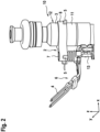
- FIGS. 2 and 3 show in perspective side view an embodiment of the mounting element 2 according to the invention, which is pre-assembled via the clip area 8 on a component housing 3 and holds a connection element 4 via the connecting element 7, namely before or after formation of the overmolding 1 with an overmolding material 1'.
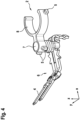
- FIGS. 4 to 6 show in different views an embodiment of the mounting element 2 according to the invention, which holds a connection element 4 for pre-assembly on the housing element 3 of a component 10 by means of a clip area 8 via a connecting element 7.
- the flat plug 4 is clipped to the connection sleeve as housing element 3 with a retaining clip as assembly element 2 during assembly and then pushed into the intended position.
- the flat plug 4 is then connected to the contacts 13 of the solenoid coil.
- the electrical conductors are connected by resistance welding.
- a clip 2, 2 ⁇ is required because simultaneous pre-assembly and welding cannot be carried out in one operation.
- a conventional clip 2' - as shown in Figure 7 is shown - deformed or displaced by the overmolding compound 1' in such a way that the conventional clip 2' is floated onto the wall of the overmolding 1 and can be seen on the surface of the overmolding.
- the current-carrying flat plugs 4 connected to the conventional clip 2' are also displaced and can thus also be floated onto the surface of the overmolding 1.
- the support knobs provided according to the invention as support elements 5 can be used directly during the manufacture of the clip 2 according to the invention at low cost. No additional parts or operations are necessary.
- Figure 3 a high-pressure injection valve as a component 10 according to the invention with the overmolding 1 - shown here semi-transparent - made of an overmolding material 1' and the clip 2 according to the invention, which is clipped onto the connection sleeve 3 of the housing 12 of the component body 11.
- the clip 2 according to the invention is firmly connected to the flat plug 4.
- the clip 2 according to the invention with four support studs 5 is positioned in the overmolding tool 20 in such a way that the clip 2 and the flat plug 4 connected to it cannot shift during the formation of the overmolding.
- the support studs 5 are positioned in such a way that they are supported on the inner wall 20-1 of the tool 20 during overmolding.
- the position can be selected in such a way that they are supported against the flow direction of the injected mass of the overmolding material 1'.
- Figure 4 to 6 a state in which the flat plug assembly 6 prior to mounting on or at the connection sleeve 3 according to Figure 3 is attached.
- more or fewer support studs 5 can also be attached.
- the shapes of the support studs can also be selected depending on the type of support and conditions.
Landscapes
- Engineering & Computer Science (AREA)
- Mechanical Engineering (AREA)
- Manufacturing & Machinery (AREA)
- Theoretical Computer Science (AREA)
- Power Engineering (AREA)
- Physics & Mathematics (AREA)
- General Engineering & Computer Science (AREA)
- General Physics & Mathematics (AREA)
- Human Computer Interaction (AREA)
- Computer Hardware Design (AREA)
- Fuel-Injection Apparatus (AREA)
- Valve Housings (AREA)
- Injection Moulding Of Plastics Or The Like (AREA)
- Insertion Pins And Rivets (AREA)
Description
- Die vorliegende Erfindung betrifft ein Montageelement, einen Montagesatz, ein Verfahren zum Montieren und ein Bauteil. Die vorliegende Erfindung betrifft insbesondere ein Montageelement, einen Montagesatz und ein Verfahren zur Montage eines Anschlusselements an ein Bauteilgehäuse eines Bauteilkörpers durch zumindest teilweises Umspritzen des Bauteilkörpers mit einem Umspritzmaterial sowie ein Bauteil, welches unter Einsatz des Montageelements, des Montagesatzes und/oder des Verfahrens zur Montage ausgebildet ist.
- Bei der industriellen Fertigung von Bauteilen müssen häufig mehrere Bauteilkomponenten miteinander verbunden und nachfolgend gemeinsam von einem einbettenden Umspritzmaterial umgeben werden. Dabei kommen Montageelemente zum Einsatz, welche zwei Bauteilkomponenten aneinander haltern und in Bezug aufeinander positionieren, wobei beim Umspritzen die Positionierung beibehalten werden soll. So ist es zum Beispiel bei vielen Ventilen notwendig, elektrische Anschlüsse eines Grundkörpers des Ventils mit einem Stecker elektrisch zu kontaktieren und dann nachfolgend zumindest einen Teil des Grundkörpers und dessen Gehäuses, sowie der elektrischen Anschlüsse und des damit kontaktierten Steckers im Umspritzmaterial einzubetten. Zum Kontaktieren des Steckers, also für die Vormontage, werden dabei zum Haltern und Positionieren Montageclips als Montageelemente eingesetzt, die den zu kontaktierenden Stecker tragen und sich am Gehäuse des Grundkörpers des Ventils zur Vormontage über Kraftschluss und/oder Formschluss anbringen lassen. Beim Umspritzen wird der Montageclip als verlorenes Element mit im Umspritzmaterial eingebettet.
- Herkömmlicherweise können bestehende Montageelemente nicht in jedem Fall beim Vorgang des Umspritzens die einmal gewählte Positionierung zwischen den Bauteilkomponenten aufrechterhalten, wodurch sich ein größeres Maß an Produktionsabweichungen einstellt.
- Aus der
KR 101 283 509 B1 - Aus den
US 2004/0020975 A1 ,US 2014/0352461 A1 undUS 2008/0187614 A1 sind auch bereits Montageelemente bekannt, um u.a. an Einspritzventilen Anschlusselemente vor dem Umspritzen vorzumontieren. - Das erfindungsgemäße Montageelement mit den Merkmalen des Anspruchs 1 weist demgegenüber den Vorteil auf, dass auch während eines Vorgangs des Umspritzens die einmal gewählte Positionierung zwischen Bauteilkomponenten, die aneinander gehaltert werden, beibehalten werden kann, wodurch sich eine höhere Zuverlässigkeit bei der Produktion einstellt. Dies wird erfindungsgemäß mit den Merkmalen des Anspruchs 1 dadurch erreicht, dass ein Montageelement und insbesondere ein Halteelement oder ein Clip zur Montage eines Anschlusselements an ein Bauteilgehäuse eines Bauteilkörpers durch zumindest teilweises Umspritzen des Bauteilkörpers mit einem Umspritzmaterial geschaffen werden, welche (i) zum Haltern und Positionieren eines Anschlusselements an einem Bauteilgehäuse eines Bauteilkörpers bei einem zumindest teilweisen Umspritzen des Bauteilkörpers mit einem Umspritzmaterial und (ii) zur zumindest teilweisen Aufnahme im Inneren eines Umspritzwerkzeugs während des Umspritzens ausgebildet sind. Das erfindungsgemäße Montageelement weist mindestens zwei Abstützelemente auf, welche so ausgebildet sind, dass sie sich in einem am Bauteilgehäuse des Bauteilkörpers gehalterten Zustand des Montageelements bei Aufnahme des Bauteilkörpers und des Montageelements im Inneren des Umspritzwerkzeugs an einer Innenseite des Umspritzwerkzeugs abstützen.
- Die Unteransprüche zeigen bevorzugte Weiterbildungen der Erfindung.
- Grundsätzlich sind alle Geometrien bei der Ausgestaltung der Abstützelemente denkbar, die die Funktion des Abstützens gewährleisten. Jedoch werden Geometrien bevorzugt, welche die sonstige Handhabung des Montageelements nicht nachteilig beeinflussen. So soll zum Beispiel durch die Abstützelemente das Anbringen des Montageelements am Bauteilkörper und insbesondere am Bauteilgehäuse nicht oder nicht nennenswert erschwert werden. Das bedeutet zum Beispiel bei der Verwendung eines Clips, dass die zum Anclippen zu überwindende Kraft durch das Vorsehen der Abstützelemente höchstens gering gesteigert werden soll.
- Eine besonders einfache und geeignete Struktur ergibt sich beim erfindungsgemäßen Montageelement dann, wenn gemäß einer bevorzugten Weiterbildung ein jeweiliges Abstützelement als Abstütznoppe ausgebildet ist.
- Eine jeweilige Noppe kann zum Beispiel im Wesentlichen ausgebildet sein in der Form eines Zylinders, eines Kegels oder Kegelstumpfs, einer Pyramide oder eines Pyramidenstumpfs, eines Prismas oder eines Prismenstumpfs, einer Kugel oder eines Teils einer Kugel, eines Ellipsoids oder eines Teils eines Ellipsoids.
- Bei einer anderen vorteilhaften Weiterbildung werden alternativ oder zusätzlich die Anzahl und/oder die gegenseitige geometrische Anordnung und/oder Orientierung relativ zueinander und/oder relativ zur Geometrie eines zu Grunde liegenden Körpers des Montageelements und/oder eines zu Grunde liegenden Umspritzwerkzeugs ausgebildet.
- Dabei können die Anzahl, die Positionierung und/oder die Orientierung der Abstützelemente so gewählt werden, dass sie sich beim Vorgang des Umspritzens zum Beispiel gegen die Strömungsrichtung des Umspritzmaterials abstützen.
- Bei einer bevorzugten Ausführungsform des erfindungsgemäßen Montageelements ist eine Mehrzahl von Abstützelementen paarweise am Montageelement ausgebildet.
- Alternativ oder zusätzlich können Elemente eines jeweiligen Paares von Abstützelementen in Bezug auf das Montageelement im Wesentlichen einander - insbesondere diametral - gegenüberstehend am Montageelement angebracht sein, insbesondere in Bezug auf einen Schwerpunkt, eine Figurenachse, eine Symmetrieachse und/oder eine Symmetrieebene des Montageelements, um bei Aufnahme im Inneren eines Umspritzwerkzeugs beim Abstützen an der Innenseite ein Paar aus Lager und Widerlager zu bilden.
- Bei einer anderen vorteilhaften zusätzlichen oder alternativen Weiterbildung des erfindungsgemäßen Montageelements ist dieses in materialeinstückiger Form ausgebildet.
- Zusätzlich oder alternativ kann das erfindungsgemäße Montageelement mit einem federnden und/oder vorgespannten Clipbereich ausgebildet sein, welcher eingerichtet ist, einen Bereich eines Bauteilgehäuses federvorgespannt, formschlüssig und/oder kraftschlüssig mit Lager und Widerlager zum Haltern und Positionieren am Bauteilgehäuse zu umfassen.
- Bei einer anderen vorteilhaften Ausgestaltungsform ist das erfindungsgemäße Montageelement mit einem Verbindungselement zur Aufnahme und zum Haltern des Anschlusselements und/oder mit oder aus einem Material ausgebildet, welches sich von einem vorgesehenen Umspritzmaterial der Auszubildenden Umspritzung unterscheidet.
- Ferner betrifft die vorliegende Erfindung auch einen Montagesatz zur Montage eines Anschlusselements an ein Bauteilgehäuse eines Bauteilkörpers durch zumindest teilweises Umspritzen des Bauteilkörpers mit einem Umspritzmaterial.
- Der erfindungsgemäße Montagesatz weist ein erfindungsgemäß ausgestaltetes Montageelement sowie ein Umspritzwerkzeug auf, wobei letzteres nach Art einer Spritzform oder Gussform ausgestaltet sein kann.
- Beim erfindungsgemäßen Montagesatz ist das Umspritzwerkzeug dazu eingerichtet, das ein Anschlusselement halternde und positionierende Montageelement derart in seinem Inneren aufzunehmen, dass sich im aufgenommenen Zustand Abstützelemente des Montageelements an einer Innenseite des Umspritzwerkzeugs abstützen, insbesondere nach Art von Lagern und Widerlagern.
- Bei einer vorteilhaften Ausführungsform des erfindungsgemäßen Montagesatzes weist dieser ein Umspritzmaterial in flüssiger oder pastöser Form auf, welches insbesondere zu einem dem Montageelement zu Grunde liegenden Material unterschiedlich ist, insbesondere in seiner Zusammensetzung.
- Gemäß einem weiteren Aspekt der vorliegenden Erfindung wird auch ein Verfahren zum Montieren eines Anschlusselements an einen Bauteilkörper oder an ein Bauteilgehäuse eines Bauteilkörpers geschaffen.
- Bei dem vorgeschlagenen Verfahren zum Montieren eines Anschlusselements wird zumindest ein Montageelement gemäß der vorliegenden Erfindung verwendet und insbesondere der erfindungsgemäße Montagesatz, wobei dabei das Anschlusselement an einem Bauteilkörpers oder an einem Bauteilgehäuse eines Bauteilkörpers mittels des Montageelements gehaltert und positioniert wird.
- Gemäß einer Weiterbildung des erfindungsgemäßen Verfahrens wird im gehalterten Zustand das das Anschlusselement haltende und positionierende Montageelement gemeinsam mit zumindest einem Teil des Bauteilkörpers oder des Bauteilgehäuses des Bauteilkörpers derart im Inneren eines Umspritzwerkzeugs und insbesondere des Umspritzwerkzeugs des Montagesatzes aufgenommen, dass sich Abstützelemente auf einer Innenseite des Umspritzwerkzeugs abstützen.
- Bei einer anderen vorteilhaften Ausgestaltungsform des erfindungsgemäßen Verfahrens wird in einem Zustand, bei welchem das das Anschlusselement halternde und positionierende Montageelement im Inneren des Umspritzwerkzeugs aufgenommen ist und bei welchem sich Abstützelemente des Montageelements an einer Innenseite des Umspritzwerkzeugs abstützen, ein Umspritzmaterial und insbesondere das Umspritzmaterial des Montagesatzes in das Umspritzwerkzeug eingefüllt und insbesondere ausgehärtet.
- Bevorzugt wird dann nachfolgend das Umspritzwerkzeug unter Freigabe des Montageelements zur Fertigstellung des Bauteils mit Bauteilkörper, Anschlusselement und Montageelement entfernt.
- Gemäß einer anderen bevorzugten Weiterbildung des erfindungsgemäßen Verfahrens wird als Bauteilkörper ein Ventil, Einspritzventil oder Hochdruckventil oder ein Grundkörper eines Ventils, Einspritzventils oder Hochdruckventils verwendet.
- Zusätzlich oder alternativ kann bei dem erfindungsgemäßen Verfahren als Anschlusselement ein Steckerelement oder ein Flachstecker aus einem elektrisch leitfähigen Material und insbesondere aus Metall verwendet werden, wobei insbesondere vor einem Umspritzen das Steckerelement als Anschlusselement mit Versorgungs- und/oder Steueranschlüssen des Ventils oder des Grundkörpers des Ventils elektrisch verbunden wird, zum Beispiel durch Schweißen oder Löten.
- Bei bevorzugten Ausgestaltungsformen des erfindungsgemäßen Verfahrens zum Montieren wird also ein Ventil, Einspritzventil oder Hochdruckventil hergestellt.
- Schließlich ist ein weiterer Aspekt der vorliegenden Erfindung die Schaffung eines Bauteils, insbesondere eines elektrischen Bauteils, eines Ventils, eines Hochdruckventils oder eines Einspritzventils.
- Das erfindungsgemäße Bauteil weist eine Umspritzung auf, in welcher ein erfindungsgemäßes Montageelement zum Teil eingebettet ist.
- Insbesondere ist das erfindungsgemäße Bauteil auf der Grundlage einer Ausführungsform des erfindungsgemäßen Verfahrens zum Montieren hergestellt.
- Unter Bezugnahme auf die beigefügten Figuren werden Ausführungsformen der Erfindung im Detail beschrieben.
- Figur 1
- zeigt in geschnittener Draufsicht eine Ausführungsform des erfindungsgemäßen Montagesatzes mit einem erfindungsgemäßen Montageelement im Inneren eines Umspritzwerkzeugs.
- Figuren 2 und 3
- zeigen in perspektivischer Seitenansicht eine Ausführungsform des erfindungsgemäßen Montageelements, welches an einem Bauteilgehäuse vormontiert ist und ein Anschlusselement haltert, und zwar vor und nach Umspritzung mit einem Umspritzmaterial.
- Figuren 4 bis 6
- zeigen in verschiedenen Ansichten eine Ausführungsform des erfindungsgemäßen Montageelements, welches ein Anschlusselement zur Vormontage haltert.
- Figur 7
- zeigt analog zur
Figur 1 ein herkömmliches Montageelement in einem Umspritzwerkzeug. - Nachfolgend werden unter Bezugnahme auf die
Figuren 1 bis 7 Ausführungsbeispiele der Erfindung und der technische Hintergrund im Detail beschrieben. Gleiche und äquivalente sowie gleich oder äquivalent wirkende Elemente und Komponenten werden mit denselben Bezugszeichen bezeichnet. Nicht in jedem Fall ihres Auftretens wird die Detailbeschreibung der bezeichneten Elemente und Komponenten wiedergegeben. - Die dargestellten Merkmale und weiteren Eigenschaften können in beliebiger Form voneinander isoliert und beliebig miteinander kombiniert werden, ohne den Kern der Erfindung zu verlassen.
- Bevor auf die Erfindung im Detail eingegangen wird, sollen zunächst unter Bezugnahme auf
Figur 7 ein herkömmlicher Montagesatz 100' und insbesondere ein herkömmliches Montageelement 2` in einem Umspritzwerkzeug 20 erläutert werden. - In
Figur 7 ist also in geschnittener Draufsicht ein herkömmlicher Montagesatz 100' dargestellt. Dieser besteht aus einem Umspritzwerkzeug 20, bestehend aus einem ersten Formteil 21 und einem zweiten Formteil 22, die in zusammengefügter Anordnung gemäßFigur 7 eine geschlossene Spritzform mit einem Inneren 23 bilden. - Im Inneren 23 des Umspritzwerkzeugs 20 ist in der in
Figur 7 dargestellten Situation ein herkömmliches Montageelement 2', welches auch als Clip bezeichnet werden kann, gezeigt. Das herkömmliche Montageelement ist im Schnitt spiegelsymmetrisch zur Achse X ausgebildet, das heißt das Montageelement 2' als Ganzes ist zu einer Ebene spiegelsymmetrisch aufgebaut, die senkrecht zur Zeichenebene steht und die Achse X enthält. - Das herkömmliche Montageelement 2' gemäß der Ausführungsform aus
Figur 7 weist einen Clipbereich 8 auf, mit welchem das herkömmliche Montageelement 2' an einem Grundkörper eines Bauteils, welcher hier nicht dargestellt ist, angebracht werden kann, und zwar mittels Formschluss und/oder Kraftschluss. - Zur Aufnahme einer vorzumontierenden Komponente, zum Beispiel eines Anschlusselements, eines Steckers oder dergleichen, weist das herkömmliche Montageelement 2' ein Verbindungselements 7 auf, welches auch als Verbindungsstück bezeichnet werden kann und welches eingerichtet ist, die vorzumontierende Komponente zu Haltern.
- Entlang dieser Symmetrieebene lassen sich auch das erste und das zweite Formteil 21, 22 des Umspritzwerkzeugs 20 voneinander trennen.
- Die in
Figur 7 dargestellte Situation verdeutlicht, dass das herkömmliche Montageelement 2` zwar vollständig im Inneren 23 des Umspritzwerkzeugs 20 enthalten ist, aber tatsächlich vollkommen beabstandet ist von der Innenseite 20-1 der ersten und zweiten Formteile 21 und 22. Das bedeutet, dass zwischen der Innenseite 20-1 und dem herkömmlichen Montageelement 2' mit Clipbereich 8 und Verbindungselement 7 eine Lücke 50 ausgebildet ist. - Im Betrieb ergibt sich aus der in
Figur 7 gezeigten Anordnung, dass beim Vorgang des Umspritzens das herkömmliche Montageelement 2` vollständig vom Umspritzmaterial umspült wird. Bei entsprechender Zähigkeit und/oder bei entsprechendem Druck können die auf das herkömmliche Montageelement 2' aufgeprägten Kräfte nicht durch entsprechende Gegenlager kompensiert werden, so dass bei entsprechender Stärke der Kräfte sich das vormontierte herkömmliche Montageelement 2' mit der gehalterten vorzumontierenden Komponente hinsichtlich Position und/oder Orientierung verschieben kann. - Dies führt herkömmlicherweise zu Qualitätseinbußen bei der Produktion.
- Dieses Problem wird erfindungsgemäß durch das Vorsehen entsprechender Abstützelemente 5 am erfindungsgemäßen Montageelement 2 und insbesondere mit Anordnung an dessen Außenumfang vermieden.
- Im Vergleich zu
Figur 7 zeigtFigur 1 in geschnittener Draufsicht eine Ausführungsform des erfindungsgemäßen Montagesatzes 100 mit einem erfindungsgemäßen Montageelement 2, welches im Inneren 23 eines Umspritzwerkzeugs 20 angeordnet ist. - Im Unterschied zur Anordnung gemäß
Figur 7 ist deutlich zu erkennen, dass der Clipbereich 8 und das Verbindungselement 7 jeweils mit einem Paar von Abstützelementen 5 in Form von Noppen ausgebildet sind. Eine jeweilige Noppe ist hier im Wesentlichen von kreiszylindrischer Gestalt. Diese Form ist jedoch nicht zwingend. - Deutlich zu erkennen ist, dass eine jeweilige Noppe als Abstützelement 5 sich an der Innenseite 20-1, die auch als Innenfläche bezeichnet werden kann, an einem jeweiligen Formteil 21, 22 vom Inneren 23 her abstützt. Beim Zuführen von Umspritzmaterial 1' zur Ausbildung einer Umspritzung 1 werden entsprechende Kräfte, die beim Umströmen des erfindungsgemäßen Montageelements 2 auf das Montageelement 2 ausgeübt werden, durch Abstützen an der Innenseite 20-1 aufgefangen und kompensiert. Dadurch wird verhindert, dass die Kräfte zu einer Änderung der Position und/oder der Orientierung des an einem Bauteilkörper 11 vormontierten Montageelements 2 führen.
- Beim Vorgang des Umspritzens bleibt somit erfindungsgemäß das Montageelement 2 an der vorbestimmten Position und in der vorbestimmten Orientierung, so dass auch das vom Montageelement 2 gehalterte Anschlusselement 4 fixiert in der vorgewählten Position und Orientierung verbleibt.
- Die
Figuren 2 und3 zeigen in perspektivischer Seitenansicht eine Ausführungsform des erfindungsgemäßen Montageelements 2, welches über den Clipbereich 8 an einem Bauteilgehäuse 3 vormontiert ist und über das Verbindungselement 7 ein Anschlusselement 4 haltert, und zwar vor bzw. nach Ausbildung der Umspritzung 1 mit einem Umspritzmaterial 1'. - Die
Figuren 4 bis 6 zeigen in verschiedenen Ansichten einer Ausführungsform des erfindungsgemäßen Montageelements 2, welches zur Vormontage am Gehäuseelement 3 eines Bauteils 10 mittels eines Clipbereichs 8 über ein Verbindungselement 7 ein Anschlusselement 4 zur Vormontage haltert. - Diese und weitere Merkmale und Eigenschaften der vorliegenden Erfindung werden an Hand der folgenden Darlegungen weiter erläutert:
Bei einem Einspritzventil als Bauteil 10 wird der Flachstecker 4 mit einem Halteclip als Montageelements 2 bei der Montage an die Anschlusshülse als Gehäuseelement 3 geclipt und anschließend auf die vorgesehene Position geschoben. Anschließend wir der Flachstecker 4 mit den Kontakten 13 der Magnetspule verbunden. In diesem Fall werden die elektrischen Leiter durch Widerstandschweißen verbunden. - Ein Clip 2, 2` wird benötigt, da ein gleichzeitiges Vormontieren und Schweißen in einem Arbeitsgang nicht ausgeführt werden kann.
- Bei der Ausbildung der Umspritzung 1 des Einspritzventils 10 wird ein herkömmlicher Clip 2' - wie dies in
Figur 7 dargestellt ist - durch die Umspritzungsmasse 1' so verformt oder verschoben, dass der herkömmliche Clip 2' auf die Wandung der Umspritzung 1 aufgeschwemmt wird und auf der Oberfläche der Umspritzung zu sehen ist. Durch das Verformen und Verschieben der Position des herkömmlichen Clips 2' werden auch die mit dem herkömmlichen Clip 2' verbundenen stromführenden Flachstecker 4 verschoben und können so auch auf die Oberfläche der Umspritzung 1 geschwemmt werden. - Es ist eine Aufgabe der vorliegenden Erfindung, mit möglichst einfachen und kostengünstigen Mitteln das Aufschwimmen des herkömmlichen Clips 2' und die daraus folgende Verschiebung der stromführenden Flachstecker 4 zu vermeiden.
- Ein Verstärken des herkömmlichen Clips 2', um die Verformung zu verhindern, hätte zur Folge, dass sich die zu überwindende Clipkraft erhöht.
- Eine andere Möglichkeit wäre die Veränderung der Anströmung oder anderer Einstellparameter der Maschine beim Ausbilden der Umspritzung 1. Dies ist jedoch in vielen Fällen technisch oder aus Kostengründen nicht möglich.
- Die erfindungsgemäß vorgesehenen Abstütznoppen als Abstützelemente 5 können direkt bei der Herstellung des erfindungsgemäßen Clips 2 kostengünstig hergestellt werden. Es sind keine zusätzlichen Teile oder Arbeitsgänge notwendig.
- Unter anderem zeigt
Figur 3 ein Hochdruckeinspritzventil als erfindungsgemäßes Bauteil 10 mit der Umspritzung 1 - hier halbtransparent dargestellt - aus einem Umspritzmaterial 1' und dem erfindungsgemäßen Clip 2, der auf die Anschlusshülse 3 des Gehäuses 12 des Bauteilkörpers 11 aufgeclipt wird. Der erfindungsgemäße Clip 2 ist mit dem Flachstecker 4 fest verbunden. - In dem beschriebenen Fall wird der erfindungsgemäße Clip 2 mit vier Abstütznoppen 5 in dem Umspritzungswerkzeug 20 so positioniert, dass der Clip 2 und der mit ihm verbundene Flachstecker 4 sich beim Ausbilden der Umspritzung nicht verschieben können.
- Die Abstütznoppen 5 werden so positioniert, dass sie sich beim Umspritzen im Werkzeug 20 an der Werkzeuginnenwand 20-1 abstützen. Die Position kann dabei so gewählt werden, dass sie sich gegen die Strömungsrichtung der eingespritzten Masse des Umspritzmaterials 1' abstützen.
- Unter anderem zeigen die
Figur 4 bis 6 einen Zustand, bei welchem die Flachsteckerbaugruppe 6 vor der Montage auf oder an der Anschlusshülse 3 gemäßFigur 3 angebracht ist. - Am erfindungsgemäßen Clip 2 und am Verbindungsstück 7 zum Flachstecker 4 sind in dem beschriebenen Fall vier Abstütznoppen 5 symmetrisch angebracht.
- Es können erfindungsgemäß auch mehr oder weniger Abstütznoppen 5 angebracht werden.
- Auch die Formen der Abstütznoppen können je nach Art der Abstützung und Bedingungen entsprechend gewählt werden.
Claims (9)
- Montageelement (2), insbesondere Halteelement oder Clip, zur Montage eines Anschlusselements (4) an ein Bauteilgehäuse (12) eines Bauteilkörpers (11) durch zumindest teilweises Umspritzen des Bauteilkörpers (11) mit einem Umspritzmaterial (1')- welches ausgebildet ist- zum Haltern und Positionieren eines Anschlusselements (4) an einem Bauteilgehäuse (12) eines Bauteilkörpers (11) bei einem zumindest teilweisen Umspritzen des Bauteilkörpers (11) mit einem Umspritzmaterial (1') und- zur zumindest teilweisen Aufnahme im Inneren (23) eines Umspritzwerkzeugs (20) während des Umspritzens,- welches mindestens zwei Abstützelemente (5) aufweist und- bei welchem die mindestens zwei Abstützelemente (5) so ausgebildet sind, dass sie sich in einem am Bauteilgehäuse (12) des Bauteilkörpers (11) gehalterten Zustand des Montageelements (2) bei Aufnahme des Bauteilkörpers (11) und des Montageelements (2) im Inneren (23) des Umspritzwerkzeugs (20) an einer Innenseite (20-1) des Umspritzwerkzeugs (20) abstützen,dadurch gekennzeichnet,
dass das Montageelement (2) aus einem Clipbereich (8) und einem Verbindungselement (7) besteht, wobei das Montagelement (2) über den Clipbereich (8) an dem Bauteilgehäuse (12) vormontiert ist und über das Verbindungselement (7) das Anschlusselement (4) haltert, wobei der Clipbereich (8) und das Verbindungselement (7) jeweils mit einem Paar von Abstützelementen (5) in Form von Noppen ausgebildet sind. - Montageelement (2) nach einem der vorangehenden Ansprüche,- bei welchem eine Mehrzahl von Abstützelementen (5) derart paarweise am Montageelement (2) ausgebildet ist,- dass Elemente eines jeweiligen Paares von Abstützelementen (5) in Bezug auf das Montageelement (2) im Wesentlichen einander - insbesondere diametral - gegenüberstehend am Montageelement (2) angebracht sind, insbesondere in Bezug auf einen Schwerpunkt, eine Figurenachse, eine Symmetrieachse und/oder eine Symmetrieebene des Montageelements (2), um bei Aufnahme im Inneren (23) eines Umspritzwerkzeugs (20) beim Abstützen an der Innenseite (20-1) ein Paar aus Lager und Widerlager zu bilden.
- Montageelement (2) nach einem der vorangehenden Ansprüche, welches ausgebildet ist - insbesondere in materialeinstückiger Form -- mit einem federnden und/oder vorgespannten Clipbereich (8), welcher eingerichtet ist, einen Bereich eines Bauteilgehäuses (12) federvorgespannt, formschlüssig und/oder kraftschlüssig mit Lager und Widerlager zum Haltern und Positionieren am Bauteilgehäuse (12) zu umfassen.
- Montagesatz (100) zur Montage eines Anschlusselements (4) an ein Bauteilgehäuse (12) eines Bauteilkörpers (11) durch zumindest teilweises Umspritzen des Bauteilkörpers (11) mit einem Umspritzmaterial (1'),- mit- einem Montageelement (2) nach einem der Ansprüche 1 bis 3 und- einem Umspritzwerkzeug (20), insbesondere nach Art einer Spritzform oder Gussform,- wobei das Umspritzwerkzeug (20) dazu eingerichtet ist, das ein Anschlusselement (4) halternde und positionierende Montageelement (2) derart in seinem Inneren (23) aufzunehmen, dass sich im aufgenommenen Zustand Abstützelemente (5) des Montageelements (2) an einer Innenseite (20-1) des Umspritzwerkzeugs (20) abstützen, insbesondere nach Art von Lagern und Widerlagern.
- Verfahren zum Montieren eines Anschlusselements (4) an ein Bauteilgehäuse (12) eines Bauteilkörpers (11),
bei welchem unter Verwendung eines Montageelements (2) nach einem der Ansprüche 1 bis 3 und/oder eines Montagesatzes (100) nach Anspruch 4 das Anschlusselement (4) an einem Bauteilgehäuse (12) eines Bauteilkörpers (11) mittels des Montageelements (2) gehaltert und positioniert wird. - Verfahren nach Anspruch 5,
bei welchem im gehalterten Zustand das das Anschlusselement (4) halternde und positionierende Montageelement (2) gemeinsam mit zumindest einem Teil des Bauteilgehäuses (12) des Bauteilkörpers (11) derart im Inneren (23) eines Umspritzwerkzeugs (20) und insbesondere des Umspritzwerkzeugs (20) des Montagesatzes (100) aufgenommen wird, dass sich Abstützelemente (5) auf einer Innenseite (20-1) des Umspritzwerkzeugs (20) abstützen. - Verfahren nach Anspruch 6, bei welchem- in einem Zustand, bei welchem das das Anschlusselement (4) halternde und positionierende Montageelement (2) im Inneren (23) des Umspritzwerkzeugs (20) aufgenommen ist und bei welchem sich Abstützelemente (5) des Montageelements (2) an einer Innenseite (20-1) des Umspritzwerkzeugs (20) abstützen, ein Umspritzmaterial (1') und insbesondere das Umspritzmaterial (1') des Montagesatzes (100) in das Umspritzwerkzeug (20) eingefüllt und insbesondere ausgehärtet wird und- nachfolgend das Umspritzwerkzeug (20) unter Freigabe des Montageelements (2) zur Fertigstellung des Bauteils (10) mit Bauteilkörper (11), Anschlusselement (4) und Montageelement (2) entfernt wird.
- Verfahren nach einem der Ansprüche 5 bis 7, bei welchem- als Bauteilkörper (11) ein Ventil, Einspritzventil oder Hochdruckventil oder ein Grundkörper eines Ventils, Einspritzventils oder Hochdruckventils verwendet wird,- als Anschlusselement (4) ein Steckerelement oder ein Flachstecker aus einem elektrisch leitfähigen Material und insbesondere aus Metall verwendet wird und insbesondere vor einem Umspritzen das Steckerelement mit Versorgungs- und/oder Steueranschlüssen des Ventils oder Grundkörpers des Ventils elektrisch verbunden wird, insbesondere durch Schweißen oder Löten, und/oder- bei welchem ein Ventil, Einspritzventil oder Hochdruckventil hergestellt wird.
- Einspritzventil,- welches eine Umspritzung (1) aufweist und bei welchem in der Umspritzung (1) ein Montageelement (2) nach einem der Ansprüche 1 bis 3 zumindest teilweise eingebettet ist und/oder- welches mittels eines Verfahrens nach einem der Ansprüche 5 bis 8 ausgebildet ist.
Applications Claiming Priority (2)
| Application Number | Priority Date | Filing Date | Title |
|---|---|---|---|
| DE102017212971.9A DE102017212971A1 (de) | 2017-07-27 | 2017-07-27 | Montageelement, Montagesatz, Verfahren zum Montieren und Bauteil |
| PCT/EP2018/065310 WO2019020257A1 (de) | 2017-07-27 | 2018-06-11 | Montageelement, montagesatz, verfahren zum montieren und bauteil |
Publications (2)
| Publication Number | Publication Date |
|---|---|
| EP3658347A1 EP3658347A1 (de) | 2020-06-03 |
| EP3658347B1 true EP3658347B1 (de) | 2024-09-18 |
Family
ID=62599591
Family Applications (1)
| Application Number | Title | Priority Date | Filing Date |
|---|---|---|---|
| EP18731047.9A Active EP3658347B1 (de) | 2017-07-27 | 2018-06-11 | Montageelement, montagesatz, verfahren zum montieren und bauteil |
Country Status (7)
| Country | Link |
|---|---|
| US (1) | US11331835B2 (de) |
| EP (1) | EP3658347B1 (de) |
| JP (1) | JP7082183B2 (de) |
| KR (2) | KR20200033859A (de) |
| CN (1) | CN110944819A (de) |
| DE (1) | DE102017212971A1 (de) |
| WO (1) | WO2019020257A1 (de) |
Families Citing this family (1)
| Publication number | Priority date | Publication date | Assignee | Title |
|---|---|---|---|---|
| CN115087803B (zh) * | 2019-12-18 | 2024-09-24 | 罗伯特·博世有限公司 | 包括端子接片的燃料喷射器 |
Citations (3)
| Publication number | Priority date | Publication date | Assignee | Title |
|---|---|---|---|---|
| DE20203315U1 (de) * | 2002-03-01 | 2003-07-10 | Robert Bosch Gmbh, 70469 Stuttgart | Flachsteckerumspritzung, insbesondere im Bereich des Flachsteckeraustritts |
| US7655319B2 (en) * | 2007-02-02 | 2010-02-02 | Continental Automotive Systems Us, Inc. | Plastic positioning pin for overmolded product |
| KR101283509B1 (ko) * | 2013-04-05 | 2013-07-12 | 에스디(주) | 인서트 사출 성형용 접속단자 |
Family Cites Families (28)
| Publication number | Priority date | Publication date | Assignee | Title |
|---|---|---|---|---|
| AT288090B (de) * | 1966-11-09 | 1971-02-25 | Bosch Gmbh Robert | Elektromagnetisch betätigbares Einspritzventil für zeitgesteuerte Niederdruck-Kraftstoffeinspritz-Anlage von Brennkraftmaschinen |
| US5507089A (en) * | 1992-05-22 | 1996-04-16 | Component Sales & Consultants, Inc. | Method of assembly of a variable reluctance sensor |
| FR2698819B1 (fr) * | 1992-12-03 | 1995-02-17 | Saint Romain Cie Ets | Procédé de fabrication d'un manche surmoulé de fouet culinaire et manche obtenu. |
| JPH11132127A (ja) * | 1996-11-13 | 1999-05-18 | Denso Corp | 燃料噴射弁及びその組立方法 |
| US5944262A (en) * | 1997-02-14 | 1999-08-31 | Denso Corporation | Fuel injection valve and its manufacturing method |
| JP3654564B2 (ja) * | 1999-03-02 | 2005-06-02 | 矢崎総業株式会社 | 成形コネクタの製造方法 |
| EP1262654A4 (de) | 2000-01-26 | 2005-04-06 | Hitachi Ltd | Elektromagnetisch betätigter brennstoffinjektor |
| JP2001272109A (ja) * | 2000-03-28 | 2001-10-05 | Toto Ltd | 温水洗浄装置便座用熱交換タンク |
| JP2002276505A (ja) | 2001-03-19 | 2002-09-25 | Unisia Jecs Corp | 燃料噴射弁及びその製造方法 |
| US6687997B2 (en) | 2001-03-30 | 2004-02-10 | Siemens Automotive Corporation | Method of fabricating and testing a modular fuel injector |
| US6722558B2 (en) | 2002-07-31 | 2004-04-20 | Robert Bosch Corporation | Method of soldering metallic terminals |
| JP5146711B2 (ja) * | 2003-05-29 | 2013-02-20 | アイシン精機株式会社 | 樹脂封止品製造方法及びケース |
| JP2005036696A (ja) | 2003-07-18 | 2005-02-10 | Hitachi Ltd | 電磁駆動式燃料噴射弁 |
| JP4576212B2 (ja) | 2004-11-24 | 2010-11-04 | 日立オートモティブシステムズ株式会社 | インサート射出成形用金型 |
| FR2878464B1 (fr) * | 2004-11-30 | 2007-06-22 | Faurecia Interieur Ind Snc | Procede de fabrication d'un element d'habillage interieur, et element d'habillage interieur sans defaut central |
| JP4758205B2 (ja) | 2005-11-18 | 2011-08-24 | トヨタ自動車株式会社 | 成形体の製造方法 |
| FR2957463B1 (fr) * | 2010-03-09 | 2012-09-28 | Bontaz Centre Sa | Dispositif de connexion electrique etanche a travers une paroi |
| DE102010031277A1 (de) * | 2010-07-13 | 2012-01-19 | Robert Bosch Gmbh | Kraftstoffeinspritzventil mit reduzierter Bauteileanzahl |
| DE102011121412A1 (de) | 2011-12-17 | 2013-06-20 | Continental Automotive Gmbh | Verfahren zur Herstellung eines Sensors und Sensor |
| JP6154106B2 (ja) * | 2012-06-13 | 2017-06-28 | 矢崎総業株式会社 | 電線端末接続部の樹脂モールド方法及び樹脂モールド用の金型 |
| CN103660140B (zh) * | 2012-08-30 | 2016-01-06 | 鼎佳(天津)汽车电子有限公司 | 气压传感器的骨架结构 |
| US9209544B2 (en) * | 2013-01-31 | 2015-12-08 | Heraeus Precious Metals Gmbh & Co. Kg | Lead connector with distal frame and method of manufacture |
| JP6011449B2 (ja) | 2013-05-14 | 2016-10-19 | 日立金属株式会社 | モールドコネクタの製造方法 |
| EP2860009B1 (de) * | 2013-10-11 | 2019-01-09 | Ems-Patent Ag | Verfahren zu der Herstellung von verstärkten Formkörper |
| DE102014208425A1 (de) * | 2013-11-28 | 2015-05-28 | Continental Teves Ag & Co. Ohg | Verfahren zum Herstellen eines Sensors |
| US9636888B2 (en) | 2015-02-04 | 2017-05-02 | Ford Global Technologies, Llc | Injection molding of hollow articles |
| US9664297B2 (en) * | 2015-02-06 | 2017-05-30 | Mueller International, Llc | Main valve with grooved rigid internal structure |
| DE102015226452A1 (de) * | 2015-12-22 | 2017-06-22 | Robert Bosch Gmbh | Ventil zum Zumessen eines Fluids |
-
2017
- 2017-07-27 DE DE102017212971.9A patent/DE102017212971A1/de not_active Withdrawn
-
2018
- 2018-06-11 WO PCT/EP2018/065310 patent/WO2019020257A1/de not_active Ceased
- 2018-06-11 KR KR1020207002436A patent/KR20200033859A/ko not_active Ceased
- 2018-06-11 US US16/633,476 patent/US11331835B2/en active Active
- 2018-06-11 CN CN201880049850.7A patent/CN110944819A/zh active Pending
- 2018-06-11 KR KR1020237030299A patent/KR102872499B1/ko active Active
- 2018-06-11 JP JP2020503759A patent/JP7082183B2/ja active Active
- 2018-06-11 EP EP18731047.9A patent/EP3658347B1/de active Active
Patent Citations (3)
| Publication number | Priority date | Publication date | Assignee | Title |
|---|---|---|---|---|
| DE20203315U1 (de) * | 2002-03-01 | 2003-07-10 | Robert Bosch Gmbh, 70469 Stuttgart | Flachsteckerumspritzung, insbesondere im Bereich des Flachsteckeraustritts |
| US7655319B2 (en) * | 2007-02-02 | 2010-02-02 | Continental Automotive Systems Us, Inc. | Plastic positioning pin for overmolded product |
| KR101283509B1 (ko) * | 2013-04-05 | 2013-07-12 | 에스디(주) | 인서트 사출 성형용 접속단자 |
Also Published As
| Publication number | Publication date |
|---|---|
| JP2020528515A (ja) | 2020-09-24 |
| JP7082183B2 (ja) | 2022-06-07 |
| KR20200033859A (ko) | 2020-03-30 |
| CN110944819A (zh) | 2020-03-31 |
| US11331835B2 (en) | 2022-05-17 |
| DE102017212971A1 (de) | 2019-01-31 |
| EP3658347A1 (de) | 2020-06-03 |
| KR20230145110A (ko) | 2023-10-17 |
| KR102872499B1 (ko) | 2025-10-20 |
| US20200156294A1 (en) | 2020-05-21 |
| WO2019020257A1 (de) | 2019-01-31 |
Similar Documents
| Publication | Publication Date | Title |
|---|---|---|
| EP3209916B1 (de) | Ventildichteinrichtung für ein kippankerventil und verfahren zum herstellen einer ventildichteinrichtung für ein kippankerventil | |
| DE102007053299A1 (de) | Ventilpatrone für ein Magnetventil und zugehöriges Magnetventil | |
| EP0733162A1 (de) | Verfahren zur herstellung eines magnetkreises für ein ventil | |
| DE2346154A1 (de) | Vorgefertigtes anschlusselement mit schraube und beilagscheiben sowie verfahren zu seiner herstellung | |
| WO2012007201A1 (de) | Kraftstoffeinspritzventil mit reduzierter bauteileanzahl | |
| EP1068441A1 (de) | Elektromagnetisch betätigbares ventil und verfahren zur herstellung eines magnetmantels für ein ventil | |
| DE602004000933T2 (de) | Kraftstoffeinspritzeinrichtung für eine Brennkraftmaschine, insbesondere eines Kraftfahrzeugs | |
| DE19712922A1 (de) | Brennstoffeinspritzventil | |
| DE602004012541T2 (de) | Methode zur Herstellung eines Brennstoffeinspritzventils für eine Brennkraftmaschine und Einspritzventil hergestellt gemäss dieser Methode | |
| WO2019020257A1 (de) | Montageelement, montagesatz, verfahren zum montieren und bauteil | |
| DE4108665C2 (de) | Einstellbuchse für ein elektromagnetisch betätigbares Ventil | |
| DE19932747B4 (de) | Verfahren zur Herstellung eines Druckregelventils für ein Automatikgetriebe eines Kraftfahrzeuges und nach dem Verfahren hergestelltes Druckregelventil | |
| DE102012221897A1 (de) | Elektrische Kontaktanordnung zur Kontaktierung einer Spule | |
| DE3149541A1 (de) | Verfahren zum herstellen eines dichtelements | |
| DE102018200084B4 (de) | Verfahren zur Herstellung einer elektromagnetischen Ventilanordnung sowie elektromagnetische Ventilanordnung | |
| DE1765099B2 (de) | Elektrische steckvorrichtung | |
| EP3292592B1 (de) | Batterieklemme und verfahren zur herstellung einer batterieklemme | |
| EP2978564B2 (de) | Spannnest mit fixierelementen | |
| WO2020200615A1 (de) | Kugelgelenk für ein fahrwerk eines fahrzeugs und verfahren zum herstellen eines solchen kugelgelenks | |
| WO2021099007A1 (de) | Elektromagnetische betätigungseinrichtung | |
| DE10319632A1 (de) | Pilotmagnetventil | |
| DE69208998T2 (de) | Herstellung von Zündkerzen | |
| DE10254524B4 (de) | Verfahren zur Herstellung eines Halters mit einer Planarantenne sowie Halter für eine Planarantenne | |
| DE102019217459A1 (de) | Kontaktanordnung für ein elektronisches Bauelement | |
| DE102024123650A1 (de) | Funktionsteil für einen Magnetkern eines Elektromagneten, Magnetanordnung, Magnetventil und Verfahren zur Herstellung einer Magnetanordnung |
Legal Events
| Date | Code | Title | Description |
|---|---|---|---|
| STAA | Information on the status of an ep patent application or granted ep patent |
Free format text: STATUS: UNKNOWN |
|
| STAA | Information on the status of an ep patent application or granted ep patent |
Free format text: STATUS: THE INTERNATIONAL PUBLICATION HAS BEEN MADE |
|
| PUAI | Public reference made under article 153(3) epc to a published international application that has entered the european phase |
Free format text: ORIGINAL CODE: 0009012 |
|
| STAA | Information on the status of an ep patent application or granted ep patent |
Free format text: STATUS: REQUEST FOR EXAMINATION WAS MADE |
|
| 17P | Request for examination filed |
Effective date: 20200227 |
|
| AK | Designated contracting states |
Kind code of ref document: A1 Designated state(s): AL AT BE BG CH CY CZ DE DK EE ES FI FR GB GR HR HU IE IS IT LI LT LU LV MC MK MT NL NO PL PT RO RS SE SI SK SM TR |
|
| AX | Request for extension of the european patent |
Extension state: BA ME |
|
| DAV | Request for validation of the european patent (deleted) | ||
| DAX | Request for extension of the european patent (deleted) | ||
| STAA | Information on the status of an ep patent application or granted ep patent |
Free format text: STATUS: EXAMINATION IS IN PROGRESS |
|
| 17Q | First examination report despatched |
Effective date: 20220125 |
|
| REG | Reference to a national code |
Ref legal event code: R079 Ipc: B29C0045140000 Ref country code: DE Ref document number: 502018015152 Country of ref document: DE Free format text: PREVIOUS MAIN CLASS: B29C0045160000 |
|
| GRAP | Despatch of communication of intention to grant a patent |
Free format text: ORIGINAL CODE: EPIDOSNIGR1 |
|
| STAA | Information on the status of an ep patent application or granted ep patent |
Free format text: STATUS: GRANT OF PATENT IS INTENDED |
|
| RIC1 | Information provided on ipc code assigned before grant |
Ipc: H01R 43/24 20060101ALN20240612BHEP Ipc: B29L 31/00 20060101ALN20240612BHEP Ipc: B29C 45/00 20060101ALI20240612BHEP Ipc: B29C 33/12 20060101ALI20240612BHEP Ipc: B29C 45/14 20060101AFI20240612BHEP |
|
| INTG | Intention to grant announced |
Effective date: 20240626 |
|
| GRAS | Grant fee paid |
Free format text: ORIGINAL CODE: EPIDOSNIGR3 |
|
| GRAA | (expected) grant |
Free format text: ORIGINAL CODE: 0009210 |
|
| STAA | Information on the status of an ep patent application or granted ep patent |
Free format text: STATUS: THE PATENT HAS BEEN GRANTED |
|
| AK | Designated contracting states |
Kind code of ref document: B1 Designated state(s): AL AT BE BG CH CY CZ DE DK EE ES FI FR GB GR HR HU IE IS IT LI LT LU LV MC MK MT NL NO PL PT RO RS SE SI SK SM TR |
|
| REG | Reference to a national code |
Ref country code: GB Ref legal event code: FG4D Free format text: NOT ENGLISH |
|
| REG | Reference to a national code |
Ref country code: CH Ref legal event code: EP |
|
| REG | Reference to a national code |
Ref country code: IE Ref legal event code: FG4D Free format text: LANGUAGE OF EP DOCUMENT: GERMAN |
|
| REG | Reference to a national code |
Ref country code: DE Ref legal event code: R096 Ref document number: 502018015152 Country of ref document: DE |
|
| REG | Reference to a national code |
Ref country code: LT Ref legal event code: MG9D |
|
| PG25 | Lapsed in a contracting state [announced via postgrant information from national office to epo] |
Ref country code: NO Free format text: LAPSE BECAUSE OF FAILURE TO SUBMIT A TRANSLATION OF THE DESCRIPTION OR TO PAY THE FEE WITHIN THE PRESCRIBED TIME-LIMIT Effective date: 20241218 |
|
| PG25 | Lapsed in a contracting state [announced via postgrant information from national office to epo] |
Ref country code: GR Free format text: LAPSE BECAUSE OF FAILURE TO SUBMIT A TRANSLATION OF THE DESCRIPTION OR TO PAY THE FEE WITHIN THE PRESCRIBED TIME-LIMIT Effective date: 20241219 Ref country code: FI Free format text: LAPSE BECAUSE OF FAILURE TO SUBMIT A TRANSLATION OF THE DESCRIPTION OR TO PAY THE FEE WITHIN THE PRESCRIBED TIME-LIMIT Effective date: 20240918 |
|
| PG25 | Lapsed in a contracting state [announced via postgrant information from national office to epo] |
Ref country code: BG Free format text: LAPSE BECAUSE OF FAILURE TO SUBMIT A TRANSLATION OF THE DESCRIPTION OR TO PAY THE FEE WITHIN THE PRESCRIBED TIME-LIMIT Effective date: 20240918 |
|
| PG25 | Lapsed in a contracting state [announced via postgrant information from national office to epo] |
Ref country code: LV Free format text: LAPSE BECAUSE OF FAILURE TO SUBMIT A TRANSLATION OF THE DESCRIPTION OR TO PAY THE FEE WITHIN THE PRESCRIBED TIME-LIMIT Effective date: 20240918 |
|
| PG25 | Lapsed in a contracting state [announced via postgrant information from national office to epo] |
Ref country code: HR Free format text: LAPSE BECAUSE OF FAILURE TO SUBMIT A TRANSLATION OF THE DESCRIPTION OR TO PAY THE FEE WITHIN THE PRESCRIBED TIME-LIMIT Effective date: 20240918 |
|
| REG | Reference to a national code |
Ref country code: NL Ref legal event code: MP Effective date: 20240918 |
|
| PG25 | Lapsed in a contracting state [announced via postgrant information from national office to epo] |
Ref country code: RS Free format text: LAPSE BECAUSE OF FAILURE TO SUBMIT A TRANSLATION OF THE DESCRIPTION OR TO PAY THE FEE WITHIN THE PRESCRIBED TIME-LIMIT Effective date: 20241218 |
|
| PG25 | Lapsed in a contracting state [announced via postgrant information from national office to epo] |
Ref country code: RS Free format text: LAPSE BECAUSE OF FAILURE TO SUBMIT A TRANSLATION OF THE DESCRIPTION OR TO PAY THE FEE WITHIN THE PRESCRIBED TIME-LIMIT Effective date: 20241218 Ref country code: NO Free format text: LAPSE BECAUSE OF FAILURE TO SUBMIT A TRANSLATION OF THE DESCRIPTION OR TO PAY THE FEE WITHIN THE PRESCRIBED TIME-LIMIT Effective date: 20241218 Ref country code: LV Free format text: LAPSE BECAUSE OF FAILURE TO SUBMIT A TRANSLATION OF THE DESCRIPTION OR TO PAY THE FEE WITHIN THE PRESCRIBED TIME-LIMIT Effective date: 20240918 Ref country code: HR Free format text: LAPSE BECAUSE OF FAILURE TO SUBMIT A TRANSLATION OF THE DESCRIPTION OR TO PAY THE FEE WITHIN THE PRESCRIBED TIME-LIMIT Effective date: 20240918 Ref country code: GR Free format text: LAPSE BECAUSE OF FAILURE TO SUBMIT A TRANSLATION OF THE DESCRIPTION OR TO PAY THE FEE WITHIN THE PRESCRIBED TIME-LIMIT Effective date: 20241219 Ref country code: FI Free format text: LAPSE BECAUSE OF FAILURE TO SUBMIT A TRANSLATION OF THE DESCRIPTION OR TO PAY THE FEE WITHIN THE PRESCRIBED TIME-LIMIT Effective date: 20240918 Ref country code: BG Free format text: LAPSE BECAUSE OF FAILURE TO SUBMIT A TRANSLATION OF THE DESCRIPTION OR TO PAY THE FEE WITHIN THE PRESCRIBED TIME-LIMIT Effective date: 20240918 |
|
| PG25 | Lapsed in a contracting state [announced via postgrant information from national office to epo] |
Ref country code: NL Free format text: LAPSE BECAUSE OF FAILURE TO SUBMIT A TRANSLATION OF THE DESCRIPTION OR TO PAY THE FEE WITHIN THE PRESCRIBED TIME-LIMIT Effective date: 20240918 |
|
| PG25 | Lapsed in a contracting state [announced via postgrant information from national office to epo] |
Ref country code: PT Free format text: LAPSE BECAUSE OF FAILURE TO SUBMIT A TRANSLATION OF THE DESCRIPTION OR TO PAY THE FEE WITHIN THE PRESCRIBED TIME-LIMIT Effective date: 20250120 Ref country code: IS Free format text: LAPSE BECAUSE OF FAILURE TO SUBMIT A TRANSLATION OF THE DESCRIPTION OR TO PAY THE FEE WITHIN THE PRESCRIBED TIME-LIMIT Effective date: 20250118 |
|
| PG25 | Lapsed in a contracting state [announced via postgrant information from national office to epo] |
Ref country code: RO Free format text: LAPSE BECAUSE OF FAILURE TO SUBMIT A TRANSLATION OF THE DESCRIPTION OR TO PAY THE FEE WITHIN THE PRESCRIBED TIME-LIMIT Effective date: 20240918 Ref country code: SM Free format text: LAPSE BECAUSE OF FAILURE TO SUBMIT A TRANSLATION OF THE DESCRIPTION OR TO PAY THE FEE WITHIN THE PRESCRIBED TIME-LIMIT Effective date: 20240918 |
|
| PG25 | Lapsed in a contracting state [announced via postgrant information from national office to epo] |
Ref country code: ES Free format text: LAPSE BECAUSE OF FAILURE TO SUBMIT A TRANSLATION OF THE DESCRIPTION OR TO PAY THE FEE WITHIN THE PRESCRIBED TIME-LIMIT Effective date: 20240918 |
|
| PG25 | Lapsed in a contracting state [announced via postgrant information from national office to epo] |
Ref country code: EE Free format text: LAPSE BECAUSE OF FAILURE TO SUBMIT A TRANSLATION OF THE DESCRIPTION OR TO PAY THE FEE WITHIN THE PRESCRIBED TIME-LIMIT Effective date: 20240918 |
|
| PG25 | Lapsed in a contracting state [announced via postgrant information from national office to epo] |
Ref country code: CZ Free format text: LAPSE BECAUSE OF FAILURE TO SUBMIT A TRANSLATION OF THE DESCRIPTION OR TO PAY THE FEE WITHIN THE PRESCRIBED TIME-LIMIT Effective date: 20240918 Ref country code: PL Free format text: LAPSE BECAUSE OF FAILURE TO SUBMIT A TRANSLATION OF THE DESCRIPTION OR TO PAY THE FEE WITHIN THE PRESCRIBED TIME-LIMIT Effective date: 20240918 |
|
| PG25 | Lapsed in a contracting state [announced via postgrant information from national office to epo] |
Ref country code: SK Free format text: LAPSE BECAUSE OF FAILURE TO SUBMIT A TRANSLATION OF THE DESCRIPTION OR TO PAY THE FEE WITHIN THE PRESCRIBED TIME-LIMIT Effective date: 20240918 |
|
| REG | Reference to a national code |
Ref country code: DE Ref legal event code: R097 Ref document number: 502018015152 Country of ref document: DE |
|
| PG25 | Lapsed in a contracting state [announced via postgrant information from national office to epo] |
Ref country code: DK Free format text: LAPSE BECAUSE OF FAILURE TO SUBMIT A TRANSLATION OF THE DESCRIPTION OR TO PAY THE FEE WITHIN THE PRESCRIBED TIME-LIMIT Effective date: 20240918 |
|
| PGFP | Annual fee paid to national office [announced via postgrant information from national office to epo] |
Ref country code: GB Payment date: 20250620 Year of fee payment: 8 |
|
| PGFP | Annual fee paid to national office [announced via postgrant information from national office to epo] |
Ref country code: FR Payment date: 20250626 Year of fee payment: 8 |
|
| PLBE | No opposition filed within time limit |
Free format text: ORIGINAL CODE: 0009261 |
|
| STAA | Information on the status of an ep patent application or granted ep patent |
Free format text: STATUS: NO OPPOSITION FILED WITHIN TIME LIMIT |
|
| 26N | No opposition filed |
Effective date: 20250619 |
|
| PG25 | Lapsed in a contracting state [announced via postgrant information from national office to epo] |
Ref country code: SE Free format text: LAPSE BECAUSE OF FAILURE TO SUBMIT A TRANSLATION OF THE DESCRIPTION OR TO PAY THE FEE WITHIN THE PRESCRIBED TIME-LIMIT Effective date: 20240918 |
|
| PGFP | Annual fee paid to national office [announced via postgrant information from national office to epo] |
Ref country code: DE Payment date: 20250814 Year of fee payment: 8 |
|
| PGFP | Annual fee paid to national office [announced via postgrant information from national office to epo] |
Ref country code: IT Payment date: 20250630 Year of fee payment: 8 |
|
| REG | Reference to a national code |
Ref country code: CH Ref legal event code: H13 Free format text: ST27 STATUS EVENT CODE: U-0-0-H10-H13 (AS PROVIDED BY THE NATIONAL OFFICE) Effective date: 20260127 |
|
| PG25 | Lapsed in a contracting state [announced via postgrant information from national office to epo] |
Ref country code: MC Free format text: LAPSE BECAUSE OF FAILURE TO SUBMIT A TRANSLATION OF THE DESCRIPTION OR TO PAY THE FEE WITHIN THE PRESCRIBED TIME-LIMIT Effective date: 20240918 |
|
| PG25 | Lapsed in a contracting state [announced via postgrant information from national office to epo] |
Ref country code: LU Free format text: LAPSE BECAUSE OF NON-PAYMENT OF DUE FEES Effective date: 20250611 |
|
| REG | Reference to a national code |
Ref country code: BE Ref legal event code: MM Effective date: 20250630 |
|
| PG25 | Lapsed in a contracting state [announced via postgrant information from national office to epo] |
Ref country code: IE Free format text: LAPSE BECAUSE OF NON-PAYMENT OF DUE FEES Effective date: 20250611 |
|
| PG25 | Lapsed in a contracting state [announced via postgrant information from national office to epo] |
Ref country code: BE Free format text: LAPSE BECAUSE OF NON-PAYMENT OF DUE FEES Effective date: 20250630 |
|
| PG25 | Lapsed in a contracting state [announced via postgrant information from national office to epo] |
Ref country code: CH Free format text: LAPSE BECAUSE OF NON-PAYMENT OF DUE FEES Effective date: 20250630 |