EP3656497B1 - Welding or additive manufacturing dual wire drive system - Google Patents
Welding or additive manufacturing dual wire drive system Download PDFInfo
- Publication number
- EP3656497B1 EP3656497B1 EP19203376.9A EP19203376A EP3656497B1 EP 3656497 B1 EP3656497 B1 EP 3656497B1 EP 19203376 A EP19203376 A EP 19203376A EP 3656497 B1 EP3656497 B1 EP 3656497B1
- Authority
- EP
- European Patent Office
- Prior art keywords
- welding
- welding wire
- wire
- annular groove
- groove
- Prior art date
- Legal status (The legal status is an assumption and is not a legal conclusion. Google has not performed a legal analysis and makes no representation as to the accuracy of the status listed.)
- Active
Links
Images


Classifications
-
- B—PERFORMING OPERATIONS; TRANSPORTING
- B23—MACHINE TOOLS; METAL-WORKING NOT OTHERWISE PROVIDED FOR
- B23K—SOLDERING OR UNSOLDERING; WELDING; CLADDING OR PLATING BY SOLDERING OR WELDING; CUTTING BY APPLYING HEAT LOCALLY, e.g. FLAME CUTTING; WORKING BY LASER BEAM
- B23K9/00—Arc welding or cutting
- B23K9/12—Automatic feeding or moving of electrodes or work for spot or seam welding or cutting
- B23K9/124—Circuits or methods for feeding welding wire
- B23K9/125—Feeding of electrodes
-
- B—PERFORMING OPERATIONS; TRANSPORTING
- B23—MACHINE TOOLS; METAL-WORKING NOT OTHERWISE PROVIDED FOR
- B23K—SOLDERING OR UNSOLDERING; WELDING; CLADDING OR PLATING BY SOLDERING OR WELDING; CUTTING BY APPLYING HEAT LOCALLY, e.g. FLAME CUTTING; WORKING BY LASER BEAM
- B23K9/00—Arc welding or cutting
- B23K9/12—Automatic feeding or moving of electrodes or work for spot or seam welding or cutting
- B23K9/124—Circuits or methods for feeding welding wire
-
- B—PERFORMING OPERATIONS; TRANSPORTING
- B22—CASTING; POWDER METALLURGY
- B22F—WORKING METALLIC POWDER; MANUFACTURE OF ARTICLES FROM METALLIC POWDER; MAKING METALLIC POWDER; APPARATUS OR DEVICES SPECIALLY ADAPTED FOR METALLIC POWDER
- B22F12/00—Apparatus or devices specially adapted for additive manufacturing; Auxiliary means for additive manufacturing; Combinations of additive manufacturing apparatus or devices with other processing apparatus or devices
-
- B—PERFORMING OPERATIONS; TRANSPORTING
- B23—MACHINE TOOLS; METAL-WORKING NOT OTHERWISE PROVIDED FOR
- B23K—SOLDERING OR UNSOLDERING; WELDING; CLADDING OR PLATING BY SOLDERING OR WELDING; CUTTING BY APPLYING HEAT LOCALLY, e.g. FLAME CUTTING; WORKING BY LASER BEAM
- B23K3/00—Tools, devices, or special appurtenances for soldering, e.g. brazing, or unsoldering, not specially adapted for particular methods
- B23K3/06—Solder feeding devices; Solder melting pans
- B23K3/0607—Solder feeding devices
- B23K3/063—Solder feeding devices for wire feeding
-
- B—PERFORMING OPERATIONS; TRANSPORTING
- B23—MACHINE TOOLS; METAL-WORKING NOT OTHERWISE PROVIDED FOR
- B23K—SOLDERING OR UNSOLDERING; WELDING; CLADDING OR PLATING BY SOLDERING OR WELDING; CUTTING BY APPLYING HEAT LOCALLY, e.g. FLAME CUTTING; WORKING BY LASER BEAM
- B23K35/00—Rods, electrodes, materials, or media, for use in soldering, welding, or cutting
- B23K35/02—Rods, electrodes, materials, or media, for use in soldering, welding, or cutting characterised by mechanical features, e.g. shape
- B23K35/0255—Rods, electrodes, materials, or media, for use in soldering, welding, or cutting characterised by mechanical features, e.g. shape for use in welding
- B23K35/0261—Rods, electrodes, wires
- B23K35/0266—Rods, electrodes, wires flux-cored
-
- B—PERFORMING OPERATIONS; TRANSPORTING
- B23—MACHINE TOOLS; METAL-WORKING NOT OTHERWISE PROVIDED FOR
- B23K—SOLDERING OR UNSOLDERING; WELDING; CLADDING OR PLATING BY SOLDERING OR WELDING; CUTTING BY APPLYING HEAT LOCALLY, e.g. FLAME CUTTING; WORKING BY LASER BEAM
- B23K9/00—Arc welding or cutting
- B23K9/12—Automatic feeding or moving of electrodes or work for spot or seam welding or cutting
- B23K9/133—Means for feeding electrodes, e.g. drums, rolls, motors
- B23K9/1336—Driving means
-
- B—PERFORMING OPERATIONS; TRANSPORTING
- B23—MACHINE TOOLS; METAL-WORKING NOT OTHERWISE PROVIDED FOR
- B23K—SOLDERING OR UNSOLDERING; WELDING; CLADDING OR PLATING BY SOLDERING OR WELDING; CUTTING BY APPLYING HEAT LOCALLY, e.g. FLAME CUTTING; WORKING BY LASER BEAM
- B23K9/00—Arc welding or cutting
- B23K9/16—Arc welding or cutting making use of shielding gas
- B23K9/173—Arc welding or cutting making use of shielding gas and of a consumable electrode
- B23K9/1735—Arc welding or cutting making use of shielding gas and of a consumable electrode making use of several electrodes
-
- B—PERFORMING OPERATIONS; TRANSPORTING
- B33—ADDITIVE MANUFACTURING TECHNOLOGY
- B33Y—ADDITIVE MANUFACTURING, i.e. MANUFACTURING OF THREE-DIMENSIONAL [3-D] OBJECTS BY ADDITIVE DEPOSITION, ADDITIVE AGGLOMERATION OR ADDITIVE LAYERING, e.g. BY 3-D PRINTING, STEREOLITHOGRAPHY OR SELECTIVE LASER SINTERING
- B33Y30/00—Apparatus for additive manufacturing; Details thereof or accessories therefor
-
- B—PERFORMING OPERATIONS; TRANSPORTING
- B23—MACHINE TOOLS; METAL-WORKING NOT OTHERWISE PROVIDED FOR
- B23K—SOLDERING OR UNSOLDERING; WELDING; CLADDING OR PLATING BY SOLDERING OR WELDING; CUTTING BY APPLYING HEAT LOCALLY, e.g. FLAME CUTTING; WORKING BY LASER BEAM
- B23K35/00—Rods, electrodes, materials, or media, for use in soldering, welding, or cutting
- B23K35/02—Rods, electrodes, materials, or media, for use in soldering, welding, or cutting characterised by mechanical features, e.g. shape
-
- Y—GENERAL TAGGING OF NEW TECHNOLOGICAL DEVELOPMENTS; GENERAL TAGGING OF CROSS-SECTIONAL TECHNOLOGIES SPANNING OVER SEVERAL SECTIONS OF THE IPC; TECHNICAL SUBJECTS COVERED BY FORMER USPC CROSS-REFERENCE ART COLLECTIONS [XRACs] AND DIGESTS
- Y02—TECHNOLOGIES OR APPLICATIONS FOR MITIGATION OR ADAPTATION AGAINST CLIMATE CHANGE
- Y02P—CLIMATE CHANGE MITIGATION TECHNOLOGIES IN THE PRODUCTION OR PROCESSING OF GOODS
- Y02P10/00—Technologies related to metal processing
- Y02P10/25—Process efficiency
Definitions
- the invention relates to a welding or additive manufacturing system according to the preamble of claim 1.
- Devices, systems, and methods consistent with the invention relate to material deposition with a dual wire configuration.
- Document DD 129 180 A1 discloses a double wire feeder that ensures the transport of two welding wires to the welding head with the aim to improve the quality of the weld seam by continuously feeding filler material.
- the task is to ensure a smooth, synchronised and parallel feed of both welding wires to the welding point during single-sided arc joint welding by means of parallel wire welding.
- the feed roller of the double wire feed unit is provided with a groove on the circumference, the cross-section of which is a circular section.
- a welding or additive manufacturing wire drive system includes a first drive roll having a first annular groove, and a second drive roll having a second annular groove aligned with the first annular groove.
- a first welding wire is located between the first drive roll and the second drive roll in both of the first annular groove and the second annular groove.
- a second welding wire is located between the first drive roll and the second drive roll in both of the first annular groove and the second annular groove.
- a biasing member biases the first drive roll toward the second drive roll to force the first welding wire to contact the second welding wire.
- the first welding wire contacts each of a first sidewall portion of the first annular groove, a first sidewall portion of the second annular groove, and the second welding wire.
- the second welding wire contacts each of a second sidewall portion of the first annular groove, a second sidewall portion of the second annular groove, and the first welding wire.
- the first drive roll and the second drive roll rotate in opposite directions thereby moving the first welding wire and the second welding wire through the welding wire drive system.
- a welding or additive manufacturing wire drive system includes a first drive roll having a first circumferential groove comprising a first groove base extending between a first inner sidewall and a first outer sidewall of the first circumferential groove.
- the system further includes a second drive roll having a second circumferential groove aligned with the first circumferential groove.
- the second circumferential groove comprises a second groove base extending between a second inner sidewall and a second outer sidewall of the second circumferential groove.
- a first welding wire is located between the first drive roll and the second drive roll in both of the first circumferential groove and the second circumferential groove
- a second welding wire is located between the first drive roll and the second drive roll in both of the first circumferential groove and the second circumferential groove.
- a biasing member biases the first drive roll toward the second drive roll to force the first welding wire to contact the second welding wire.
- the first welding wire contacts each of the first inner sidewall, the second inner sidewall, and the second welding wire
- the second welding wire contacts each of the first outer sidewall, the second outer sidewall, and the first welding wire. At least one of the first welding wire and the second welding wire is offset from both of the first groove base and the second groove base.
- a welding or additive manufacturing wire drive system includes a first drive roll and a second drive roll.
- One or both of the first drive roll and the second drive roll has a circumferential groove.
- a first welding wire is located between the first drive roll and the second drive roll in the circumferential groove.
- a second welding wire is located between the first drive roll and the second drive roll in the circumferential groove.
- a biasing member biases the first drive roll toward the second drive roll to force the first welding wire to contact the second welding wire.
- the first welding wire further contacts a first sidewall portion of the circumferential groove
- the second welding wire further contacts a second sidewall portion of the circumferential groove
- both of the first welding wire and the second welding wire are offset from a base portion of the circumferential groove.
- the base portion extends between the first sidewall portion and the second sidewall portion of the circumferential groove.
- Embodiments of the present invention are described herein in the context of a welding system.
- Example welding systems include gas metal arc welding (GMAW) systems, submerged arc welding (SAW) systems, flux-cored arc welding (FCAW) systems, metal-cored arc welding (MCAW) systems, and the like.
- GMAW gas metal arc welding
- SAW submerged arc welding
- FCAW flux-cored arc welding
- MCAW metal-cored arc welding
- the electrodes described herein can be solid electrodes, embodiments of the present invention are not limited to the use of solid electrodes.
- flux-cored electrodes and metal-cored electrodes can also be used.
- embodiments of the present invention can also be used in manual, semiautomatic and robotic welding operations. Because such systems are well known, they will not be described in detail herein.
- Embodiments of the present invention will be discussed in the context of a welding system. However, in addition to welding operations, embodiments can be used in additive manufacturing processes and other welding-type processes involving driven wire electrodes (e.g., hardfacing).
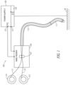
- FIG. 1 depicts an exemplary embodiment of a welding system 100.
- the welding system 100 contains a welding power source or power supply 109 which is coupled to both a welding torch 111 and a wire feeder 105.
- the power source 109 can be any known type of welding power source capable of delivering welding current and welding waveforms, for example, pulse spray, STT and/or short arc type welding waveforms. Because the construction, design and operation of such power supplies are well known, they need not be described in detail herein. It is also noted that welding power can be supplied by more than one power supply at the same time - again the operation of such systems are known.
- the power source 109 can also include a controller 120 which is coupled to a user interface to allow a user to input control or welding parameters for the welding operation.
- the controller 120 can have a processor, CPU, memory etc. to be used to control the operation of the welding process and the generation of welding waveforms.
- the torch 111 which can be constructed similar to known manual, semiautomatic or robotic welding torches and can be of a straight or gooseneck type.
- the wire feeder 105 draws wire electrodes E1 and E2 from electrode sources 101 and 103, respectively, which can be of any known type, such as reels, spools, containers or the like.
- the wire feeder 105 employs drive rolls 107 to draw the electrodes or welding wires E1 and E2 and push or pull the electrodes to the torch 111.
- the drive rolls 107 and wire feeder 105 are configured for a dual electrode welding operation. That is, they supply both electrodes E1 and E2 simultaneously to the torch 111 for creating an arc and welding the workpiece W. As shown, the wire feeder 105 is operatively connected to the power source 109 consistent with known configurations of welding operations.
- the electrodes E1 and E2 can be passed through a liner 113 to deliver the electrodes E1 and E2 to the torch 111.
- the liner 113 is appropriately sized to allow for the passage of the electrodes E1 and E2 to the torch 111.
- a standard 0.0625 inch (1.5875 mm) diameter liner 113 (which is typically used for a single 0.0625 inch (1.5875 mm) diameter electrode) can be used with no modification.
- the wire electrodes E1, E2 can have different diameters. That is, embodiments of the present invention can use an electrode of a first, larger, diameter and an electrode of a second, smaller, diameter. In such an embodiment, it may be possible to more conveniently weld two workpieces of different thicknesses.
- the larger electrode can be oriented to the larger workpiece while the smaller electrode can be oriented to the smaller workpiece.
- embodiments of the present invention can be used for many different types of welding operations including, but not limited to, GMAW, SAW, FCAW, and MCAW. Additionally, embodiments of the present invention can be utilized with different electrode types.
- a cored electrode e.g., flux-cored or metal-cored
- electrodes of differing compositions can be used to achieve desired weld properties and composition of the final weld bead.
- Two different, but compatible, consumables can be combined to create a desired weld joint.
- compatible consumables such as hardfacing wires, stainless wires, nickel alloys and steel wires of different composition can be combined.
- a mild steel wire can be combined with an overal-loyed wire to make a 309 stainless steel composition. This can be advantageous when a single consumable of the type desired does not have desirable weld properties.
- some consumables for specialized welding provide the desired weld chemistry but are extremely difficult to use and have difficulty providing a satisfactory weld.
- embodiments of the present invention allow for the use of two consumables that are easier to weld with to be combined to create the desired weld chemistry.
- Embodiments of the present invention can be used to create an alloy/deposit chemistry that is not otherwise commercially available, or otherwise very expensive to manufacture.
- two different consumables can be used to obviate the need for an expensive or unavailable consumable.
- embodiments can be used to create a diluted alloy.
- a first welding wire could be a common, inexpensive alloy and a second welding wire could be a specialty wire.
- the resulting deposit would be the average of the two wires, mixed well in the formation of a molten droplet, at the lower average cost of the two wires, over an expensive specialty wire.
- the desired deposit could be unavailable due to the lack of appropriate consumable chemistry, but could be achieved by mixing two standard alloy wires, mixed within the molten droplet and deposited as a single droplet.
- the desired deposit may be combination of tungsten carbide particles from one wire and chrome carbide particles from another.
- a larger wire housing larger parti-des within is mixed with a smaller wire containing fewer particles or smaller particles, to deposit a mixture of the two wires.
- the expected contribution from each of the wires is proportional to the size of wire.
- exemplary embodiments are discussed herein utilizing two wire electrodes simultaneously, other embodiments of the present invention can utilize more than two electrodes.
- a three or more electrode configuration can be utilized consistent with the descriptions and discussions set forth herein.
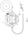
- FIG. 2 provides a perspective view of the welding system 100.
- the wire feeder 105 comprises drive rolls for conveying wire electrodes E1, E2 from electrode sources 101, 103, for use in a particular application.
- the wire electrodes E1, E2 may be drawn continuously from a reel, spool, or container (e.g., a box or a drum), and delivered to the workpiece W, which in the current embodiment is a weldment.
- the wire feeder 105 may include a drive assembly that utilizes power from one or more locomotive devices, such as an electric motor, that drive the wire electrodes E1, E2 to the application work site or workpiece W.
- the welding power source 109 may receive electrical input power from an outside source (e.g., utility power), that is directed to an onboard transformer and processor-controlled inverter or chopper circuitry, not depicted in the figures. Output from the power source 109 may be provided through welding output terminals 121 or studs of the welding power source.
- a welding gun or torch 111 and wire conduit may be electrically connected to the welding power source 109 through the welding wire feeder 105 for delivering welding current to the workpiece W in a manner known in the art. It follows that the welding wires E1, E1 are fed through the torch 111 and metered out, i.e. dispensed, at the discretion of the application and/or end user in any manner suitable for conducting the welding process.
- the electrodes E1, E1 conduct electricity for establishing a welding arc, wherein the electrodes are conveyed to the workpiece W having a voltage potential equal to or approximately equal to the output voltage of the welding power source 109, which may be substantially greater than ground.
- Different modes of conveying the wire electrodes E1, E2 are known in the art, an example of which includes pushing the electrodes to the torch 111 via power or torque provided by the locomotive device.
- Other modes of conveying the electrodes include push/pull modes that utilize multiple locomotive devices.
- the electrodes E1, E2 are delivered to the torch 111, which may have a trigger or other activation mechanism for dispensing the electrodes at the user's discretion. At times, it may be necessary to deliver the electrodes E1, E2 at varying rates of feed. Therefore, the locomotive device has an output that is adjustable for varying the wire feed speed (WFS) of the electrodes E1, E2.
- WFS wire feed speed
- a drive motor of the wire feeder 105 may be a variable speed motor to adjust the WFS.
- a drive motor 123 is shown in Figure 3 .
- the wire feeder 105 and/or drive motor(s) 123 may draw operating power from the welding power source 109, or an altogether separate power source. Still any manner of providing power to operate the welding wire feeder 105 and/or the drive motors 123 may be chosen with sound engineering judgment as is appropriate for use with the embodiments of the present invention.
- the welding wire feeder 105 may include a drive assembly, or drive roll assembly.
- the drive motor 123 also called a wire feeder motor, delivers power, i.e. torque, to convey the first and second welding wires E1, E2 through the wire feeder and to the torch 111 and subsequently to the workpiece W.
- Drive rolls 107 are included that grip the welding wires E1, E2 for pushing or pulling the welding wires in the appropriate direction, i.e. toward the workpiece W.
- Sets of drive rolls 107 are vertically aligned and have corresponding aligned annular or circumferential grooves through which the wending wires E1, E2 pass simultaneously.
- the vertically-aligned sets of drive rolls 107 rotate in opposite directions to drive the welding wires E1, E2 through the wire feeder 105.
- the upper drive rolls 107 rotate clockwise and the lower drive rolls rotate counterclockwise.
- the drive rolls 107 may be cylindrical in configuration, or more specifically disk-shaped, although the particular configuration should not be construed as limiting.
- the surface, i.e. the outer circumference, of the driver rolls 107 may be comprised of a sufficiently hardened material, like steel, that is durable and suitable for gripping the welding wires E1, E2.
- the drive rolls 107 may be disposed in pairs along the wire trajectory with each drive roll of the pair being supported on opposing sides of the welding wires E1, E2, such that respective outer circumferential portions of the rolls engage opposite sides of the wires (e.g., from above and below). It is noted that the central axes of respective drive rolls 107 extend substantially parallel with one another and generally transverse to the trajectory of the welding wires E1, E1.
- the wire feeder 105 can include a biasing member that biases the vertically-aligned sets of drive rolls 107 toward one another.
- the biasing member sets the clamping force or compression that the drive rolls 107 apply to the welding wires E1, E2.
- the wire feeder 105 can include biasing springs 125 that apply a bias force to one or more drive rolls 107 to set the compression that the drive rolls apply to the welding wires E1, E2.
- the biasing springs 125 are mounted to an adjusting rod 127 that can be moved inward and outward to adjust the compression of the biasing springs 125. The force of the biasing springs 125 is transferred to the upper drive rolls 107 via pivoting levers 129.
- the vertically-aligned sets of drive rolls 107 have corresponding aligned annular or circumferential grooves through which the wending wires E1, E2 pass simultaneously. That is, the welding wires E1, E2 are located together in the grooves of an upper drive roll and a lower drive roll. The welding wires E1, E2 are squeezed or compressed within the grooves by the bias force applied by the biasing springs 125 to the drive rolls 107. As will be explained further below, the welding wires E1, E2 are made to contact each other within the grooves when squeezed by the drive rolls 107.
- a sideways compressive force is also applied to the welding wires E1, E2 to force them together inside of the grooves.
- the sideways compressive force is provided through the shape of the sidewalls of the grooves.
- FIGs 4 and 5 illustrate an example drive roll 107.
- the drive roll has a central bore.
- the inner surface of the bore can include contoured recesses 131 for receiving projections on a driving mechanism, such as a drive gear, to transfer drive torque to the drive roll 107.
- the drive roll 107 includes one or more annular or circumferential wire receiving grooves 133, 135.
- the wire receiving grooves 133, 135 are spaced axially along the circumference of the drive roll 107.
- the wire receiving grooves 133, 135 are designed to receive two welding wires.
- Example standard welding wire diameters for use with the drive rolls 107 include 0.030 inches (0.762 mm), 0.035 inches (0.889 mm), 0.040 inches (1.016 mm), 0.045 inches (1.143 mm), etc.
- the wire receiving grooves 133, 135 can have the same width and depth as each other, or have different widths and depths to accommodate different sizes or combinations of dual welding wires. If the wire receiving grooves 133, 135 each have the same width and depth, then the drive roll 107 can be reused when one groove is worn out by simply flipping the drive roll over and reinstalling it on the wire feeder.
- the wire receiving grooves 133, 135 can be configured to simultaneously drive two wires having the same diameter, or two wires having different diameters.
- the wire receiving grooves 133, 135 have a trapezoidal shape with straight, angled or inwardly-tapered sidewalls and a flat base extending between the sidewalls.
- the wire receiving grooves 133, 135 could have other shapes besides a trapezoidal shape, such as having a curved, concave groove base for example.
- the grooves 133, 135 can include knurling or other frictional surface treatments to help grip the welding wires.
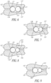
- Figures 6 through 11 show partial cross sections of example drive rolls 107 as they would be mounted on a wire feeder for supplying dual welding wires.
- the drive rolls 107 are biased together to provide a clamping force on the first E1 and the second E2 welding wires.
- the welding wires E1, E2 are both located in the annular grooves of the upper and lower drive rolls 107.
- the annular grooves are aligned and can have a trapezoidal shape.
- the trapezoidal shape is an isosceles trapezoid formed by an inner sidewall 137, an outer sidewall 139, and a groove base 141 extending between the sidewalls.
- the isosceles trapezoidal shape is inverted as a cross-sectional recess from the outer circumferential surface of the drive rolls 107.
- the welding wires E1, E2 are clamped in the annular grooves between upper and lower sidewalls 137, 139 forming the grooves and the neighboring welding wire.
- the welding wires E1, E2 are stably held via three points of contact within the annular grooves.
- This clamping system can allow both wires to be fed through the wire feeder in a consistent manner.
- the two welding wires E1, E2 support each other during feeding and pull each other along via friction. Because the inner 137 and outer 139 sidewalls of the annular grooves are angled, they apply both vertical and horizontal clamping forces on the welding wires E1, E2. The horizontal clamping force pushes the welding wires E1, E2 together, causing them to contact each other.
- the welding wires E1, E2 are clamped within the annular grooves so as to be radially offset from both of the groove bases 141. That is, the welding wires E1, E2 are pinned between each other and the angled sidewalls 137, 139 of the grooves such that gaps exist between the welding wires and the groove bases 141. This can be seen clearly in Figure 6 .
- the clamping system discussed above allows for some variability (e.g., due to manufacturing tolerances) in the diameters of the welding wires E1, E2. If each welding wire E1, E2 had its own dedicated annular groove in the drive rolls 107, and one of the welding wires was slightly larger than the other, then the smaller welding wire might not be adequately clamped between the drive rolls. In such a situation, the larger welding wire would limit the radial displacement of the drive rolls 107 toward each other, thereby preventing proper clamping of the smaller wire. This could lead to feeding problems and so-called birdnesting of the smaller welding wire during feeding.
- the clamping system discussed above can accommodate wires of different sizes because the clamping system is self-adjusting.
- Figure 8 shows drive rolls 107 having annular grooves 143 with cross sections having an acute trapezoid shape instead of an isosceles trapezoid.
- the inner 145 and outer 147 sidewalls of the grooves have different lengths and form different angles with the outer circumferential surface of the drive rolls.
- the drive rolls 107 have annular grooves 149 having a right trapezoid shape.
- Acute and right trapezoidal grooves can accommodate greater differences in welding wire diameters than isosceles trapezoids.
- acute and right trapezoidal grooves can be used when the groove is intended to drive welding wires having different diameters, such as a 0.040 inch (1.016 mm) welding wire with a 0.045 inch (1.143 mm) welding wire.
- the sidewalls and/or base of the grooves can be curved (e.g., concave or convex).
- the inside corner transitions between the sidewalls and the base of the trapezoidal grooves can be curved or radiused.
- Figure 10 shows example drive rolls having annular grooves with straight, angled sidewalls 150 joined by a concave curved or radiused groove base 152.
- the angle between the sidewalls 150 and the outer circumference of the drive roll 107 is about 150°, although other angles are possible and can be determined with sound engineering judgment.
- Figure 11 shows an example embodiment in which one drive roll 107 has a trapezoidal groove for the welding wires E1, E2, and the other drive roll 107a has a non-trapezoidal groove.
- the non-trapezoidal groove is rectangular in shape, however other shapes are possible.
- the non-trapezoidal groove could be curved, such as elliptical or rounded in shape.
- the trapezoidal groove is shown as being located on the lower drive roll 107.
- the trapezoidal groove could be located on the upper drive roll 107a and the non-trapezoidal groove located on the lower drive roll.
- the welding wires E1, E2 are clamped between respective sidewalls 137, 139 of the trapezoidal groove and the base 153 of the non-trapezoidal groove 151, and the welding wires are forced into contact with each other as discussed above.
- the welding wires E1, E2 are stably held via three points of contact within the annular grooves 107, 107a.
- Figure 12 shows an example embodiment in which one drive roll 107 has a trapezoidal groove for the welding wires E1, E2, and the other drive roll 107b has no groove, but rather directly contacts the welding wires on its outer circumferential surface 155.
- the trapezoidal groove is shown as being located on the lower drive roll 107. However, the trapezoidal groove could be located on the upper drive roll.
- the welding wires E1, E2 are clamped between respective sidewalls 137, 139 of the trapezoidal groove and the outer circumferential surface 155 of the upper drive roll 107b, and the welding wires are forced into contact with each other as discussed above.
- the welding wires E1, E2 are stably held via three points of contact.
Landscapes
- Engineering & Computer Science (AREA)
- Mechanical Engineering (AREA)
- Physics & Mathematics (AREA)
- Plasma & Fusion (AREA)
- Chemical & Material Sciences (AREA)
- Manufacturing & Machinery (AREA)
- Materials Engineering (AREA)
- Arc Welding In General (AREA)
- Wire Processing (AREA)
- Butt Welding And Welding Of Specific Article (AREA)
Applications Claiming Priority (3)
| Application Number | Priority Date | Filing Date | Title |
|---|---|---|---|
| US16/159,805 US11198192B2 (en) | 2018-10-15 | 2018-10-15 | Welding or additive manufacturing dual wire drive system |
| US201962815036P | 2019-03-07 | 2019-03-07 | |
| US16/527,328 US11426813B2 (en) | 2018-10-15 | 2019-07-31 | Welding or additive manufacturing dual wire drive system |
Publications (4)
| Publication Number | Publication Date |
|---|---|
| EP3656497A2 EP3656497A2 (en) | 2020-05-27 |
| EP3656497A3 EP3656497A3 (en) | 2020-09-09 |
| EP3656497C0 EP3656497C0 (en) | 2024-12-18 |
| EP3656497B1 true EP3656497B1 (en) | 2024-12-18 |
Family
ID=68281078
Family Applications (2)
| Application Number | Title | Priority Date | Filing Date |
|---|---|---|---|
| EP19203369.4A Active EP3656496B1 (en) | 2018-10-15 | 2019-10-15 | Welding or additive manufacturing dual wire drive system |
| EP19203376.9A Active EP3656497B1 (en) | 2018-10-15 | 2019-10-15 | Welding or additive manufacturing dual wire drive system |
Family Applications Before (1)
| Application Number | Title | Priority Date | Filing Date |
|---|---|---|---|
| EP19203369.4A Active EP3656496B1 (en) | 2018-10-15 | 2019-10-15 | Welding or additive manufacturing dual wire drive system |
Country Status (6)
| Country | Link |
|---|---|
| EP (2) | EP3656496B1 (enExample) |
| JP (2) | JP7441629B2 (enExample) |
| KR (2) | KR102719782B1 (enExample) |
| CN (2) | CN111037058A (enExample) |
| ES (1) | ES3004541T3 (enExample) |
| PL (1) | PL3656497T3 (enExample) |
Families Citing this family (12)
| Publication number | Priority date | Publication date | Assignee | Title |
|---|---|---|---|---|
| US11504788B2 (en) | 2017-08-08 | 2022-11-22 | Lincoln Global, Inc. | Dual wire welding or additive manufacturing system and method |
| US10792752B2 (en) | 2017-08-08 | 2020-10-06 | Lincoln Global, Inc. | Dual wire welding or additive manufacturing system and method |
| US10532418B2 (en) | 2017-08-08 | 2020-01-14 | Lincoln Global, Inc. | Dual wire welding or additive manufacturing contact tip and diffuser |
| US11440121B2 (en) | 2017-08-08 | 2022-09-13 | Lincoln Global, Inc. | Dual wire welding or additive manufacturing system and method |
| US11285557B2 (en) | 2019-02-05 | 2022-03-29 | Lincoln Global, Inc. | Dual wire welding or additive manufacturing system |
| US11498146B2 (en) | 2019-09-27 | 2022-11-15 | Lincoln Global, Inc. | Dual wire welding or additive manufacturing system and method |
| AU2021200318B2 (en) * | 2020-02-10 | 2025-12-11 | Lincoln Global, Inc. | Welding or additive manufacturing dual wire drive system |
| CN112548269A (zh) * | 2020-11-26 | 2021-03-26 | 西安交通大学 | 一种同步多机器人双丝结构件电弧增材装备及其控制方法 |
| US12168268B2 (en) | 2021-05-20 | 2024-12-17 | Lincoln Global, Inc. | Reduction of droplet size for CO2 shielded welding wire |
| CN115041781A (zh) * | 2022-05-20 | 2022-09-13 | 国家石油天然气管网集团有限公司 | 自动送丝装置及自动焊接系统 |
| CN116000511B (zh) * | 2022-12-26 | 2024-04-09 | 深圳市海志亿半导体工具有限公司 | 一种增强细间距送丝成形效果的劈刀刀头 |
| WO2024259407A1 (en) * | 2023-06-15 | 2024-12-19 | Lincoln Global, Inc. | Dual wire drive system |
Citations (3)
| Publication number | Priority date | Publication date | Assignee | Title |
|---|---|---|---|---|
| DD129180A1 (de) * | 1976-12-30 | 1978-01-04 | Willi Zaft | Doppeldrahtvorschubrolle zum einseitigen lichtbogenverbindungsschweissen von blechen |
| SU1763124A1 (ru) * | 1989-08-22 | 1992-09-23 | Центр научно-технического творчества молодежи "Астрон" | Способ одновременной подачи в зону сварки двух сварочных проволок |
| US7383973B2 (en) * | 2004-03-15 | 2008-06-10 | Lincoln Global, Inc. | Drive rollers for wire feeding mechanism |
Family Cites Families (26)
| Publication number | Priority date | Publication date | Assignee | Title |
|---|---|---|---|---|
| US2866079A (en) * | 1957-02-18 | 1958-12-23 | Westinghouse Electric Corp | Arc welding apparatus |
| AT313026B (de) * | 1969-12-24 | 1974-01-25 | Boehler & Co Ag Geb | Lichtbogen-Schmelzschweißverfahren |
| JPS5071536A (enExample) * | 1973-10-29 | 1975-06-13 | ||
| JPS5910869B2 (ja) * | 1974-10-12 | 1984-03-12 | 三菱電機株式会社 | 非消耗性電極式全姿勢自動溶接装置 |
| US4058700A (en) * | 1976-02-03 | 1977-11-15 | Sumitomo Metal Industries Ltd. | Method for horizontal fillet welding of steel plates |
| JPS5329726U (enExample) * | 1976-08-19 | 1978-03-14 | ||
| JPH02118671U (enExample) * | 1989-03-13 | 1990-09-25 | ||
| JP2620440B2 (ja) * | 1991-10-18 | 1997-06-11 | 新日本製鐵株式会社 | ワイヤ送給装置 |
| JPH05177351A (ja) * | 1991-12-27 | 1993-07-20 | Ishikawajima Harima Heavy Ind Co Ltd | 溶接制御装置 |
| US5981906A (en) * | 1995-08-11 | 1999-11-09 | Lincoln Global, Inc. | Method of welding the ends of pipe together using dual welding wires |
| DE19611597A1 (de) * | 1996-03-23 | 1997-09-25 | Fichtel & Sachs Ag | Einrichtung zum Doppeldrahtschweißen |
| US5816466A (en) | 1996-04-19 | 1998-10-06 | The Lincoln Electric Company | Wire feeding apparatus |
| JP3739870B2 (ja) * | 1996-10-08 | 2006-01-25 | 三菱重工業株式会社 | 複数電極ガスシールドアーク溶接用ワイヤ送給装置 |
| DE19800671C2 (de) * | 1998-01-10 | 2002-11-28 | L & P Swiss Holding Company Wi | Federwindeautomat |
| US7390989B2 (en) * | 2004-04-08 | 2008-06-24 | Illinois Tool Works Inc. | Wire feeder |
| US7531768B2 (en) * | 2004-04-08 | 2009-05-12 | Illinois Tool Works Inc. | Wire feeder pinch force mechanism |
| CN2843710Y (zh) * | 2005-12-06 | 2006-12-06 | 广州广船国际股份有限公司 | 单电源埋弧自动焊送丝系统 |
| CN201279562Y (zh) * | 2008-10-30 | 2009-07-29 | 陈伟亮 | 一种弯箍机送料装置 |
| CN201405154Y (zh) * | 2009-04-15 | 2010-02-17 | 孔祥钦 | 双驱动送双焊丝桥式自动焊接机 |
| US8278599B2 (en) * | 2009-06-11 | 2012-10-02 | Illinois Tool Works Inc. | Belt drive for feeding welding wire |
| US8569653B2 (en) * | 2009-11-02 | 2013-10-29 | Lincoln Global, Inc. | Drive roll assembly for wire feeder |
| US9839970B2 (en) | 2010-12-21 | 2017-12-12 | Lincoln Global, Inc. | Dual wire welding system and method |
| US9144862B2 (en) * | 2012-11-30 | 2015-09-29 | Illinois Tool Works Inc. | System and method for determining welding wire diameter |
| WO2015059535A1 (en) * | 2013-10-25 | 2015-04-30 | Lincoln Global, Inc. | Drive roll assembly |
| FI125568B (en) * | 2014-06-03 | 2015-11-30 | Rosendahl Nextrom Oy | Apparatus for processing optical fibers |
| CN204339099U (zh) * | 2014-11-24 | 2015-05-20 | 成都熊谷加世电器有限公司 | 金属粉芯焊丝的送丝机 |
-
2019
- 2019-10-10 KR KR1020190125550A patent/KR102719782B1/ko active Active
- 2019-10-10 KR KR1020190125551A patent/KR102719783B1/ko active Active
- 2019-10-11 JP JP2019187626A patent/JP7441629B2/ja active Active
- 2019-10-11 JP JP2019187620A patent/JP7452973B2/ja active Active
- 2019-10-12 CN CN201910965794.8A patent/CN111037058A/zh active Pending
- 2019-10-12 CN CN201910965802.9A patent/CN111037059B/zh active Active
- 2019-10-15 ES ES19203376T patent/ES3004541T3/es active Active
- 2019-10-15 EP EP19203369.4A patent/EP3656496B1/en active Active
- 2019-10-15 EP EP19203376.9A patent/EP3656497B1/en active Active
- 2019-10-15 PL PL19203376.9T patent/PL3656497T3/pl unknown
Patent Citations (3)
| Publication number | Priority date | Publication date | Assignee | Title |
|---|---|---|---|---|
| DD129180A1 (de) * | 1976-12-30 | 1978-01-04 | Willi Zaft | Doppeldrahtvorschubrolle zum einseitigen lichtbogenverbindungsschweissen von blechen |
| SU1763124A1 (ru) * | 1989-08-22 | 1992-09-23 | Центр научно-технического творчества молодежи "Астрон" | Способ одновременной подачи в зону сварки двух сварочных проволок |
| US7383973B2 (en) * | 2004-03-15 | 2008-06-10 | Lincoln Global, Inc. | Drive rollers for wire feeding mechanism |
Also Published As
| Publication number | Publication date |
|---|---|
| ES3004541T3 (en) | 2025-03-12 |
| EP3656496A3 (en) | 2020-09-02 |
| EP3656497C0 (en) | 2024-12-18 |
| JP7452973B2 (ja) | 2024-03-19 |
| KR102719782B1 (ko) | 2024-10-18 |
| KR102719783B1 (ko) | 2024-10-18 |
| EP3656497A2 (en) | 2020-05-27 |
| JP2020062687A (ja) | 2020-04-23 |
| EP3656497A3 (en) | 2020-09-09 |
| KR20200042855A (ko) | 2020-04-24 |
| CN111037058A (zh) | 2020-04-21 |
| EP3656496A2 (en) | 2020-05-27 |
| CN111037059A (zh) | 2020-04-21 |
| EP3656496C0 (en) | 2025-08-20 |
| KR20200042856A (ko) | 2020-04-24 |
| EP3656496B1 (en) | 2025-08-20 |
| CN111037059B (zh) | 2023-03-21 |
| JP2020062686A (ja) | 2020-04-23 |
| PL3656497T3 (pl) | 2025-05-12 |
| JP7441629B2 (ja) | 2024-03-01 |
Similar Documents
| Publication | Publication Date | Title |
|---|---|---|
| EP3656497B1 (en) | Welding or additive manufacturing dual wire drive system | |
| EP3693116B1 (en) | Dual wire welding or additive manufacturing system | |
| US11504787B2 (en) | Welding or additive manufacturing dual wire drive system | |
| AU2025271349A1 (en) | Welding or additive manufacturing dual wire drive system | |
| US11198192B2 (en) | Welding or additive manufacturing dual wire drive system | |
| US20230017476A1 (en) | Wire spool clutch | |
| KR102873425B1 (ko) | 이중 와이어 용접 또는 적층 제조 시스템 및 방법 | |
| US11426813B2 (en) | Welding or additive manufacturing dual wire drive system | |
| US11504788B2 (en) | Dual wire welding or additive manufacturing system and method |
Legal Events
| Date | Code | Title | Description |
|---|---|---|---|
| PUAI | Public reference made under article 153(3) epc to a published international application that has entered the european phase |
Free format text: ORIGINAL CODE: 0009012 |
|
| STAA | Information on the status of an ep patent application or granted ep patent |
Free format text: STATUS: THE APPLICATION HAS BEEN PUBLISHED |
|
| AK | Designated contracting states |
Kind code of ref document: A2 Designated state(s): AL AT BE BG CH CY CZ DE DK EE ES FI FR GB GR HR HU IE IS IT LI LT LU LV MC MK MT NL NO PL PT RO RS SE SI SK SM TR |
|
| AX | Request for extension of the european patent |
Extension state: BA ME |
|
| PUAL | Search report despatched |
Free format text: ORIGINAL CODE: 0009013 |
|
| AK | Designated contracting states |
Kind code of ref document: A3 Designated state(s): AL AT BE BG CH CY CZ DE DK EE ES FI FR GB GR HR HU IE IS IT LI LT LU LV MC MK MT NL NO PL PT RO RS SE SI SK SM TR |
|
| AX | Request for extension of the european patent |
Extension state: BA ME |
|
| RIC1 | Information provided on ipc code assigned before grant |
Ipc: B23K 9/12 20060101AFI20200806BHEP Ipc: B23K 9/133 20060101ALI20200806BHEP Ipc: B23K 9/173 20060101ALI20200806BHEP |
|
| STAA | Information on the status of an ep patent application or granted ep patent |
Free format text: STATUS: REQUEST FOR EXAMINATION WAS MADE |
|
| 17P | Request for examination filed |
Effective date: 20210309 |
|
| RBV | Designated contracting states (corrected) |
Designated state(s): AL AT BE BG CH CY CZ DE DK EE ES FI FR GB GR HR HU IE IS IT LI LT LU LV MC MK MT NL NO PL PT RO RS SE SI SK SM TR |
|
| STAA | Information on the status of an ep patent application or granted ep patent |
Free format text: STATUS: EXAMINATION IS IN PROGRESS |
|
| 17Q | First examination report despatched |
Effective date: 20231113 |
|
| GRAP | Despatch of communication of intention to grant a patent |
Free format text: ORIGINAL CODE: EPIDOSNIGR1 |
|
| STAA | Information on the status of an ep patent application or granted ep patent |
Free format text: STATUS: GRANT OF PATENT IS INTENDED |
|
| INTG | Intention to grant announced |
Effective date: 20240731 |
|
| GRAS | Grant fee paid |
Free format text: ORIGINAL CODE: EPIDOSNIGR3 |
|
| GRAA | (expected) grant |
Free format text: ORIGINAL CODE: 0009210 |
|
| STAA | Information on the status of an ep patent application or granted ep patent |
Free format text: STATUS: THE PATENT HAS BEEN GRANTED |
|
| AK | Designated contracting states |
Kind code of ref document: B1 Designated state(s): AL AT BE BG CH CY CZ DE DK EE ES FI FR GB GR HR HU IE IS IT LI LT LU LV MC MK MT NL NO PL PT RO RS SE SI SK SM TR |
|
| REG | Reference to a national code |
Ref country code: CH Ref legal event code: EP |
|
| REG | Reference to a national code |
Ref country code: DE Ref legal event code: R096 Ref document number: 602019063581 Country of ref document: DE |
|
| REG | Reference to a national code |
Ref country code: IE Ref legal event code: FG4D |
|
| U01 | Request for unitary effect filed |
Effective date: 20250109 |
|
| U07 | Unitary effect registered |
Designated state(s): AT BE BG DE DK EE FI FR IT LT LU LV MT NL PT RO SE SI Effective date: 20250114 |
|
| REG | Reference to a national code |
Ref country code: ES Ref legal event code: FG2A Ref document number: 3004541 Country of ref document: ES Kind code of ref document: T3 Effective date: 20250312 |
|
| PG25 | Lapsed in a contracting state [announced via postgrant information from national office to epo] |
Ref country code: HR Free format text: LAPSE BECAUSE OF FAILURE TO SUBMIT A TRANSLATION OF THE DESCRIPTION OR TO PAY THE FEE WITHIN THE PRESCRIBED TIME-LIMIT Effective date: 20241218 |
|
| PG25 | Lapsed in a contracting state [announced via postgrant information from national office to epo] |
Ref country code: NO Free format text: LAPSE BECAUSE OF FAILURE TO SUBMIT A TRANSLATION OF THE DESCRIPTION OR TO PAY THE FEE WITHIN THE PRESCRIBED TIME-LIMIT Effective date: 20250318 |
|
| PG25 | Lapsed in a contracting state [announced via postgrant information from national office to epo] |
Ref country code: GR Free format text: LAPSE BECAUSE OF FAILURE TO SUBMIT A TRANSLATION OF THE DESCRIPTION OR TO PAY THE FEE WITHIN THE PRESCRIBED TIME-LIMIT Effective date: 20250319 |
|
| PG25 | Lapsed in a contracting state [announced via postgrant information from national office to epo] |
Ref country code: RS Free format text: LAPSE BECAUSE OF FAILURE TO SUBMIT A TRANSLATION OF THE DESCRIPTION OR TO PAY THE FEE WITHIN THE PRESCRIBED TIME-LIMIT Effective date: 20250318 |
|
| RAP4 | Party data changed (patent owner data changed or rights of a patent transferred) |
Owner name: LINCOLN GLOBAL, INC. |
|
| U1H | Name or address of the proprietor changed after the registration of the unitary effect |
Owner name: LINCOLN GLOBAL, INC.; US |
|
| PG25 | Lapsed in a contracting state [announced via postgrant information from national office to epo] |
Ref country code: SM Free format text: LAPSE BECAUSE OF FAILURE TO SUBMIT A TRANSLATION OF THE DESCRIPTION OR TO PAY THE FEE WITHIN THE PRESCRIBED TIME-LIMIT Effective date: 20241218 |
|
| PG25 | Lapsed in a contracting state [announced via postgrant information from national office to epo] |
Ref country code: IS Free format text: LAPSE BECAUSE OF FAILURE TO SUBMIT A TRANSLATION OF THE DESCRIPTION OR TO PAY THE FEE WITHIN THE PRESCRIBED TIME-LIMIT Effective date: 20250418 |
|
| PG25 | Lapsed in a contracting state [announced via postgrant information from national office to epo] |
Ref country code: SK Free format text: LAPSE BECAUSE OF FAILURE TO SUBMIT A TRANSLATION OF THE DESCRIPTION OR TO PAY THE FEE WITHIN THE PRESCRIBED TIME-LIMIT Effective date: 20241218 |
|
| PG25 | Lapsed in a contracting state [announced via postgrant information from national office to epo] |
Ref country code: CZ Free format text: LAPSE BECAUSE OF FAILURE TO SUBMIT A TRANSLATION OF THE DESCRIPTION OR TO PAY THE FEE WITHIN THE PRESCRIBED TIME-LIMIT Effective date: 20241218 |
|
| PLBE | No opposition filed within time limit |
Free format text: ORIGINAL CODE: 0009261 |
|
| STAA | Information on the status of an ep patent application or granted ep patent |
Free format text: STATUS: NO OPPOSITION FILED WITHIN TIME LIMIT |
|
| 26N | No opposition filed |
Effective date: 20250919 |
|
| U20 | Renewal fee for the european patent with unitary effect paid |
Year of fee payment: 7 Effective date: 20251022 |