EP3655293B1 - Verschlusselement - Google Patents
Verschlusselement Download PDFInfo
- Publication number
- EP3655293B1 EP3655293B1 EP18734525.1A EP18734525A EP3655293B1 EP 3655293 B1 EP3655293 B1 EP 3655293B1 EP 18734525 A EP18734525 A EP 18734525A EP 3655293 B1 EP3655293 B1 EP 3655293B1
- Authority
- EP
- European Patent Office
- Prior art keywords
- bracket
- closure element
- ball
- extension
- ball joint
- Prior art date
- Legal status (The legal status is an assumption and is not a legal conclusion. Google has not performed a legal analysis and makes no representation as to the accuracy of the status listed.)
- Active
Links
Images



Classifications
-
- B—PERFORMING OPERATIONS; TRANSPORTING
- B60—VEHICLES IN GENERAL
- B60S—SERVICING, CLEANING, REPAIRING, SUPPORTING, LIFTING, OR MANOEUVRING OF VEHICLES, NOT OTHERWISE PROVIDED FOR
- B60S1/00—Cleaning of vehicles
- B60S1/02—Cleaning windscreens, windows or optical devices
- B60S1/04—Wipers or the like, e.g. scrapers
- B60S1/0413—Modular wiper assembly
- B60S1/0422—Modular wiper assembly having a separate transverse element
- B60S1/0425—Modular wiper assembly having a separate transverse element characterised by the attachment of the wiper shaft holders to the transverse element
-
- B—PERFORMING OPERATIONS; TRANSPORTING
- B60—VEHICLES IN GENERAL
- B60S—SERVICING, CLEANING, REPAIRING, SUPPORTING, LIFTING, OR MANOEUVRING OF VEHICLES, NOT OTHERWISE PROVIDED FOR
- B60S1/00—Cleaning of vehicles
- B60S1/02—Cleaning windscreens, windows or optical devices
- B60S1/04—Wipers or the like, e.g. scrapers
- B60S1/06—Wipers or the like, e.g. scrapers characterised by the drive
- B60S1/16—Means for transmitting drive
- B60S1/18—Means for transmitting drive mechanically
- B60S1/24—Means for transmitting drive mechanically by rotary cranks
-
- B—PERFORMING OPERATIONS; TRANSPORTING
- B60—VEHICLES IN GENERAL
- B60S—SERVICING, CLEANING, REPAIRING, SUPPORTING, LIFTING, OR MANOEUVRING OF VEHICLES, NOT OTHERWISE PROVIDED FOR
- B60S1/00—Cleaning of vehicles
- B60S1/02—Cleaning windscreens, windows or optical devices
- B60S1/04—Wipers or the like, e.g. scrapers
- B60S1/043—Attachment of the wiper assembly to the vehicle
- B60S1/0441—Attachment of the wiper assembly to the vehicle characterised by the attachment means
- B60S1/0447—Attachment of the wiper assembly to the vehicle characterised by the attachment means non-screw fixation, (e.g. snap-in, bayonnet-type..)
-
- F—MECHANICAL ENGINEERING; LIGHTING; HEATING; WEAPONS; BLASTING
- F16—ENGINEERING ELEMENTS AND UNITS; GENERAL MEASURES FOR PRODUCING AND MAINTAINING EFFECTIVE FUNCTIONING OF MACHINES OR INSTALLATIONS; THERMAL INSULATION IN GENERAL
- F16C—SHAFTS; FLEXIBLE SHAFTS; ELEMENTS OR CRANKSHAFT MECHANISMS; ROTARY BODIES OTHER THAN GEARING ELEMENTS; BEARINGS
- F16C11/00—Pivots; Pivotal connections
- F16C11/04—Pivotal connections
- F16C11/06—Ball-joints; Other joints having more than one degree of angular freedom, i.e. universal joints
- F16C11/0619—Ball-joints; Other joints having more than one degree of angular freedom, i.e. universal joints the female part comprising a blind socket receiving the male part
- F16C11/0623—Construction or details of the socket member
-
- F—MECHANICAL ENGINEERING; LIGHTING; HEATING; WEAPONS; BLASTING
- F16—ENGINEERING ELEMENTS AND UNITS; GENERAL MEASURES FOR PRODUCING AND MAINTAINING EFFECTIVE FUNCTIONING OF MACHINES OR INSTALLATIONS; THERMAL INSULATION IN GENERAL
- F16C—SHAFTS; FLEXIBLE SHAFTS; ELEMENTS OR CRANKSHAFT MECHANISMS; ROTARY BODIES OTHER THAN GEARING ELEMENTS; BEARINGS
- F16C11/00—Pivots; Pivotal connections
- F16C11/04—Pivotal connections
- F16C11/06—Ball-joints; Other joints having more than one degree of angular freedom, i.e. universal joints
- F16C11/0685—Manufacture of ball-joints and parts thereof, e.g. assembly of ball-joints
- F16C11/069—Manufacture of ball-joints and parts thereof, e.g. assembly of ball-joints with at least one separate part to retain the ball member in the socket; Quick-release systems
-
- F—MECHANICAL ENGINEERING; LIGHTING; HEATING; WEAPONS; BLASTING
- F16—ENGINEERING ELEMENTS AND UNITS; GENERAL MEASURES FOR PRODUCING AND MAINTAINING EFFECTIVE FUNCTIONING OF MACHINES OR INSTALLATIONS; THERMAL INSULATION IN GENERAL
- F16C—SHAFTS; FLEXIBLE SHAFTS; ELEMENTS OR CRANKSHAFT MECHANISMS; ROTARY BODIES OTHER THAN GEARING ELEMENTS; BEARINGS
- F16C11/00—Pivots; Pivotal connections
- F16C11/04—Pivotal connections
- F16C11/06—Ball-joints; Other joints having more than one degree of angular freedom, i.e. universal joints
- F16C11/0695—Mounting of ball-joints, e.g. fixing them to a connecting rod
-
- F—MECHANICAL ENGINEERING; LIGHTING; HEATING; WEAPONS; BLASTING
- F16—ENGINEERING ELEMENTS AND UNITS; GENERAL MEASURES FOR PRODUCING AND MAINTAINING EFFECTIVE FUNCTIONING OF MACHINES OR INSTALLATIONS; THERMAL INSULATION IN GENERAL
- F16C—SHAFTS; FLEXIBLE SHAFTS; ELEMENTS OR CRANKSHAFT MECHANISMS; ROTARY BODIES OTHER THAN GEARING ELEMENTS; BEARINGS
- F16C11/00—Pivots; Pivotal connections
- F16C11/04—Pivotal connections
- F16C11/10—Arrangements for locking
- F16C11/103—Arrangements for locking frictionally clamped
- F16C11/106—Arrangements for locking frictionally clamped for ball joints
-
- F—MECHANICAL ENGINEERING; LIGHTING; HEATING; WEAPONS; BLASTING
- F16—ENGINEERING ELEMENTS AND UNITS; GENERAL MEASURES FOR PRODUCING AND MAINTAINING EFFECTIVE FUNCTIONING OF MACHINES OR INSTALLATIONS; THERMAL INSULATION IN GENERAL
- F16C—SHAFTS; FLEXIBLE SHAFTS; ELEMENTS OR CRANKSHAFT MECHANISMS; ROTARY BODIES OTHER THAN GEARING ELEMENTS; BEARINGS
- F16C2326/00—Articles relating to transporting
- F16C2326/01—Parts of vehicles in general
- F16C2326/09—Windscreen wipers, e.g. pivots therefore
Definitions
- the invention relates to a closure element for a ball joint, a ball shell of a ball joint, a ball joint with such a closure element and a wiper system with such a closure element, as well as a method for arranging the closure element on the ball joint.
- Ball joints are known in which a pin with a ball head is arranged in a spherical shell.
- the pin with the ball head is not secured in the ball socket, which means that the ball joint can easily be dismantled unintentionally.
- the pin with the ball head can be pulled out of the ball socket unintentionally.
- Such disadvantageous ball joints are installed, for example, in wiper systems for motor vehicles.
- a closure element according to the preamble of claim 1 is from WO 2005/033531 A1 known.
- the present invention according to the main claim and the independent claims has the advantage that the ball joint is secured by a locking element in such a way that unwanted dismantling of the ball joint is not possible.
- the closure element is essentially constructed from two brackets arranged transversely to one another.
- the first bracket is designed to secure the ball joint.
- the first bracket secures the ball joint when the closure element is arranged in an end position on the ball socket.
- the second bracket positions the closure element with respect to the spherical shell in an intermediate position that the closure element assumes during an assembly process of the ball joint.
- This intermediate position is particularly advantageous if, for example, a pin with a ball head is pushed into the spherical socket.
- the intermediate position can be defined by stops so that it can be equivalent to a stop position.
- the first bracket includes a locking side and a bracket side, the sides being formed by the side walls.
- the locking side has a fastening slot which is designed as a recess in the side wall assigned to the locking side.
- the fastening slot is used to fix the locking element on the ball joint.
- the bracket side also has the second bracket.
- the bracket side is also designed with a recess, the recess being able to accommodate part of the spherical shell of the ball joint.
- the recess on the side of the bracket is usually larger than the recess in the fastening slot.
- a closure element can be provided by the independent claims, which first moves into an end position on the
- Spherical shell is arranged. After the closure element has been fully positioned, the ball head is pushed through the first bracket and secured by it. The second bracket ensures the end position of the closure element. This means that no two positioning steps are necessary.
- the first bracket is advantageously U-shaped. Its essential shape is U-shaped and includes two legs with free ends.
- the U-shaped bracket is equipped with a channel-shaped cross-sectional profile along its main direction.
- the channel-shaped cross-sectional profile is open inwards, so that the channel forms a closed U-shaped contour towards the outside, which extends essentially along the direction of the bracket.
- the trough-shaped bracket thus has two side walls which extend radially inwards from the U-shaped outer contour. Such a shaped bracket makes it possible to securely hold the ball joint.
- the advantageous second bracket extends transversely from the bracket side of the first bracket.
- the second bracket can also extend vertically from the side of the bracket.
- the second bracket is designed in an arc shape from one leg to the other leg of the first bracket.
- the Arches can have curves and/or corners.
- the arch can comprise straight as well as curved sections, with the second bracket extending from the free ends of the first bracket.
- the second bracket is formed directly on the free ends.
- the second bracket is U-shaped, you get a fastening element that is easy to assemble and fits tightly.
- the second bracket is preferably designed as a strip which has a certain width in the direction of extension of the legs of the first bracket.
- the specific width of the second bracket can be shorter than the length of the legs of the first bracket, so that the second bracket only arises from a partial section of the first bracket.
- An edge of the second bracket can be designed flush with the free ends of the legs of the first bracket or the edge can be spaced from the free ends.
- the U-shaped bracket is designed like a band from one leg to the other.
- the second bracket has no free ends.
- the second bracket can also cover the entire length of the legs of the first bracket, so that the specific width of the second bracket has the length of the legs.
- the second bracket is equipped with a recess for a positioning extension.
- the recess is preferably formed on the edge of the second bracket in such a way that it is open to the outside, so that the positioning extension can be guided into the recess by a lateral movement along the direction of extension of the legs of the first bracket.
- the second bracket is designed to be resilient.
- the second bracket can thus be deflected elastically transversely to the first bracket.
- the elastic deflection is preferably carried out by the positioning extension when it is pushed under the bracket.
- the advantageous positioning extension is arranged on the spherical shell.
- the spherical shell is bowl-shaped and has one side that is the second bracket is facing. This side is dome-shaped.
- the positioning extension is arranged on the dome.
- the positioning extension is preferably arranged eccentrically on the dome.
- the dome can be round or square.
- a particularly advantageous embodiment is provided by a ramp-shaped positioning extension.
- the positioning extension has an inclined plane that fulfills a ramp function.
- the ramp of the positioning extension is directed in the sliding direction of the closure element.
- the second bracket is guided along the ramp, and the inclined plane deflects the second bracket elastically transversely to the first bracket. Using the inclined plane, this elastic deflection of the second bracket is possible by a sliding movement in the direction of the legs of the first bracket.
- At least one extension is formed on the edge of the opening of the spherical shell, which cooperates with the fastening slot.
- two extensions are formed, which are arranged in a line along the diameter in alignment with the sliding direction. The extensions position and fix the spherical shell with respect to the closure element in an end position of the assembly process.
- the advantageous assembly process for the ball joint includes a spherical shell that is injected into a joint rod.
- the spherical shell preferably has the positioning extension and two extensions on the opposite side.
- the closure element is placed on the end of the joint rod where the spherical shell is injected.
- the fastening slot is turned to the side of the extensions so that the second bracket is on the side of the positioning extension.
- the closure element is pushed partially over the spherical shell in the direction of the legs of the first bracket along the joint rod until the free ends of the legs abut a first extension.
- the first extension is diametrically opposite the second extension with respect to the spherical shell opening and is further away from the end of the joint rod than the second extension.
- the positioning extension In this position, the positioning extension is locked into the recess. While pushing into this stop position, the positioning extension is pushed to the edge of the second Bracket brought in, which is directed towards the free ends. While pushing, the positioning extension is guided under the second bracket, whereby it is deflected elastically. When the positioning extension is passed under the bracket, it enters the recess and the second bracket relaxes into its starting position. This enables a secure and clear assembly of the closure element.
- a pin with a ball head can be pushed through the fastening slot into the opening of the spherical shell. Since the fastening slot reduces the opening of the spherical shell and the ball head of the pin has a larger dimension than the fastening slot, the legs of the first bracket are spread by the ball head. The legs are spread in an elastic manner. If the ball head passes the fastening slot and enters the ball socket through the opening of the ball socket, the legs relax into their starting position.
- the closure element is then pushed further until the second extension comes to rest in a corresponding recess within the fastening slot.
- This corresponding recess is designed to complement the second extension and is formed at an axial end of the fastening slot.
- a projection protruding into the fastening slot comes to rest on the first extension, so that the two extensions are arranged between the complementary recess and the projection with respect to the sliding direction.
- the closure element is securely mounted in this end position.
- the first bracket has the two legs with free ends and an arch that is shaped after the end of the joint rod.
- An edge of the articulated rod can engage in the channel-like structure of the first bracket.
- the edge of the joint rod at the end of the joint rod can rest in the channel in the end position.
- the closure element can be brought directly in one step into an end position in which the extensions engage in the slot.
- the positioning extension is arranged in the end position in the recess in the second bracket and remains there.
- the recess is arranged along the direction of extension of the legs of the first bracket at the level of a transition region between the legs and the arch of the bracket. This can be achieved by the second bracket having a certain bracket width that corresponds to the length of the legs of the first bracket. This results in a robust design.
- this position of the recess can be achieved by forming the recess in a tab that extends to the transition area of the legs and the arch, while the width of the second bracket does not take up the entire length of the legs. This ensures excellent elasticity of the closure element.
- a depression can be formed on the top of the second bracket, which can be intended for a finger.
- the recess serves to hold the closure element mounted in the end position when inserting the ball head.
- a technician's finger can be placed on the recess and the ball head can be joined.
- FIG. 1 a motor vehicle is shown that has a wiper system 1000, which is operated by means of a linkage 1001.
- the linkage 1001 is connected to the windshield wiper and a motor.
- This connection is realized by at least one ball joint 12.
- this ball joint 12 is equipped with a closure element 10 from the figures.
- FIG. 2 Such a closure element 10 is in Figure 2 pictured.
- the closure element 10 has two brackets 14, 16.
- the two brackets 14, 16 are arranged transversely, preferably perpendicularly, to one another.
- the first bracket 14 is U-shaped. It has a groove-shaped cross-sectional profile along its main direction of extension. The groove-shaped cross-sectional profile is opened radially inwards and its side walls form recesses.
- the first bracket 14 also has free ends 26 which are formed on legs of the U-shaped first bracket 14. There are two legs that run essentially parallel to each other. The legs are of equal length and merge into a common round section which lies opposite the free ends 26. In the area of the free ends 26, the annular cross-sectional profile is open.
- the second bracket 16 is U-shaped and extends from one leg to the other leg on a bracket side 20 of the first bracket 14.
- the second bracket 16 is strip-shaped. The width of the strip extends in the direction of expansion of the legs of the first bracket 14.
- the bracket side 20 is formed by the side walls.
- the second bracket 16 has an edge that is directed towards the free ends 26. This edge is flush with the free ends 26.
- a recess 24 is formed on an opposite edge of the second bracket 16. This recess 24 is in the middle of the edge of the second bracket 26, so that this recess 24 is open towards the round section of the first bracket 14. Essentially, the recess 24 is provided with a rectangular cross section.
- a spherical shell 100 is molded on in the area of the end of a joint rod 1001.
- the spherical shell 100 is shown with its opening 109.
- the opening 109 is surrounded by a collar on which two diametrically opposite extensions 106 are arranged.
- the two extensions 106 are aligned with the mounting direction 1 of the closure element 10.
- the two extensions 106 extend essentially vertically from the collar in a common direction which is transverse to the legs of the first bracket 14.
- a locking side 18 of the first bracket 14 is formed, which contains a fastening slot 22.
- the blocking side 18 is provided by the side walls of the groove-shaped cross-sectional profile.
- the fastening slot 22 has a dimension transverse to the legs that is smaller than the diameter of the opening 109.
- the fastening slot 22 extends in the direction of the legs of the first arch 14.
- a recess 23 in the fastening slot 22 is complementary to a second extension 107 of the two extensions 106, with the second extension 107 in the assembly direction 1 of the closure element 10 at the beginning of assembly as in Figure 3 a) is closer to the closure element 10 than a first extension 105 of the two extensions 106.
- the second extension 107 is closer to the round section of the first bracket 14.
- the second extension 107 has a trapezoidal cross section in a plane parallel to the opening 109, with the complementary recess 23 has a trapezoidal contour.
- the first extension 105 essentially has a T-shaped cross section. The T-shaped cross section is aligned in assembly direction 1.
- a projection 19 is formed on each edge side of the fastening slot 22 assigned to the respective leg.
- the projection 19 is shaped like a step in the mounting direction 1 along the fastening slot 22.
- the step of the projection 19 is directed in the direction of the complementary recess 23.
- the projection 19 extends flush to the free end 26.
- a chamfer 21 is formed on the projection 19 on the outward-facing side of the locking side 18.
- the chamfer 21 has a triangular contour, the tip of which coincides with the step of the projection 19.
- the step tapers inwards through the chamfer 21.
- the step is complementary to the undercut 103 of the T-shaped cross section of the first extension 105.
- the second extension 107 is first pushed into the fastening slot 22 by pushing the closure element 10 Figure 3 b) promoted.
- the joint rod 1001 is pushed into the annular cross-sectional profile of the U-shaped first bracket 14.
- the closure element 10 is pushed in the assembly direction 1 until it reaches a stop position according to Figure 3 c) reached.
- the stop position is also in Figure 4 shown.
- the free end hits 26 facing part of the projection 19 to the first extension 105.
- the projection 19 rests on the side of the first extension 105 that faces the opening 109.
- the second paragraph 107 is spaced apart from its complementary recesses 23.
- the positioning extension 101 is also arranged in the recess 24.
- An axially directed surface which extends essentially vertically from an underside of a dome of the spherical shell 100, abuts the contour of the recess 24.
- the positioning extension 101 In order to get into the stop position, the positioning extension 101 is pushed under the second arch 16, while the joint rod 1001 is pushed into the groove-shaped cross-sectional profile of the first bracket 14. So that easy pushing can take place, the positioning extension 101 has an inclined plane 103 in the assembly direction 1.
- the inclined plane 103 causes a ramp-like formation of the positioning extension 101.
- the second bracket 16 is tilted relative to the mounting direction 1, so that the mounting direction 1 and an imaginary line along at least the area of the underside of the second sheet 16, along which the positioning extension 101 is guided , include an acute angle.
- the hinge rod 1001 and the underside of the second arch 16 form an acute angle that is open towards the hinge rod.
- the inclined plane 103 acts at least with the tilted underside of the second sheet 16 together in such a way that it can easily be pushed under the second sheet 16.
- the second arch 16 is elastic and is additionally deflected upwards by the positioning extension.
- the area of the recess 24 has a chamfer 25 on the edge facing the round section, which prevents the underside of the second arch 16 from colliding with the dome of the spherical shell 100.
- the underside is spaced from the dome by the chamfer 25. If this chamfer 25 were not there, the edge of the second arch 16 would rest on the dome due to the acute angle between the second arch 16 and the joint rod 1001.
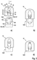
- Figure 5 shows the assembly of a pin 108 with a ball head 110 in the ball socket 100 of the ball joint 12, with the closure element 10 in the stop position.
- the contour of the ball head is shown schematically by the dashed line.
- the pin 108 is inserted into the spherical shell 100 in a joining direction 2 according to a).
- the steps according to b) to d) take place.
- the ball head 110 has a smaller diameter dimension than the dimension of the width of the fastening slot 22. Since the opening 109 is now blocked by the edge of the fastening slot 22 and the projections 19, a pin 108 to be joined rests first on three contact points 111 , as shown in b) by three black schematic dots. It rests on the bevels 21 and radially on the second extension 107. According to their inclined plane, the chamfers 21 guide the ball head 110 of the pin 108 against the radially directed side of the second extension 107 and inwards through the opening 109.
- the legs of the first bracket 14 are spread in a direction 3 transverse to the legs. This takes place until the projections 19 no longer rest on the radially directed side of the first extension 105, but are spaced further apart from one another than the first extension 105 is wide. Now the sliding can continue in the assembly direction 1 of the closure element 10. The sliding is carried out by the inclined plane of the chamfer 19 supported or accomplished completely alone. When the ball head 110 has now completely slipped from the chamfers 19, it can slide through the opening 109 into the spherical shell 100. Further pushing leads to the legs relaxing when the projections 19 are positioned behind the second extension 105. They snap into the undercuts 103 and the opening 109 is narrowed in such a way that the ball head 110 cannot be removed.
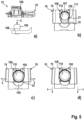
- FIG 6 an alternative embodiment of the closure element 10 is shown.
- the structure and function of this alternative is the same as the previously described embodiment of the closure element 10. Therefore, the features, in particular with regard to the fastening slot 22 and / or the assembly of the ball head and / or the bracket side and / or the locking side, can be used with the other embodiment can be combined with this alternative.
- the alternative closure element 10 can be mounted directly in the end position.
- the closure element points in Figure 6 a) two legs 601 with free ends and an arch 600 between the legs 601, the first bracket 14 being constructed by the legs and the arch.
- a transition region 602 is arranged between a leg and the bow, at which the bow merges into the leg. This may also be the case in the previous embodiment.
- the second bracket 16 has a recess 605 for a technician's finger.
- the fitter can press on the recess 605 and generate a counter-holding force for mounting the ball head 110.
- a tab 603 is formed centrally on the second bracket, which extends from an edge of the bracket 16 facing the bow 600.
- the tab has a semicircular contour in which the recess 604 for the positioning extension 101 is formed.
- the recess is formed at the distal end of the tab and in the direction of extension of the legs 601 at the level of the transition region 602.
- the positioning extension 101 is arranged in the recess 604 and the tab 604 covers the spherical shell 100.
- the ball head 110 is arranged in the spherical shell after assembly, which is in Figure 6 b) 1.
- Figure 6 b) 1. can be seen, whereby the ball head 110 has been joined over bevels 607 which are arranged in the contour of the fastening slot 22.
- the edge of the joint rod 1001 sits in the trough-like structure of the first bracket 14.
- the bracket 14 surrounds the end of the joint rod 1001 his thighs and the bow. This can also apply to the previously described embodiments.
- the assembly of the closure element Figure 6 is also carried out by sliding the joint rod in the longitudinal direction, as is done in the previous embodiments.
- the thighs are also spread and extensions on the spherical shell can be grasped.
- FIG 6 c) is shown how a ball head is inserted into the spherical shell 100 in the direction of the arrow.
- the ball head 110 is pushed through the fastening slot 22 into the spherical shell 100, with the legs 601 spreading.
- the ball head 110 is attached to the fastening slot 22, as in Figure 6 c) 1.
- a fitter can now press his finger on the recess 605 and generate a counter-holding force for assembly in the direction of the arrow.
- the ball head begins to slide into the spherical shell and at the same time the legs 601 spread, which in Figure 6 c) 2 is shown.
- the spreading reaches a maximum value when the bevels are arranged approximately at the location of the largest diameter of the ball head in the direction of the arrow, which is in Figure 6 c) 3. is shown.
- the legs relax back to their original state and block the opening in the ball socket for the ball head and prevent the ball head from being easily removed.
Landscapes
- Engineering & Computer Science (AREA)
- General Engineering & Computer Science (AREA)
- Mechanical Engineering (AREA)
- Pivots And Pivotal Connections (AREA)
Applications Claiming Priority (3)
| Application Number | Priority Date | Filing Date | Title |
|---|---|---|---|
| DE102017212407 | 2017-07-19 | ||
| DE102017213439 | 2017-08-02 | ||
| PCT/EP2018/066958 WO2019015918A1 (de) | 2017-07-19 | 2018-06-25 | Verschlusselement |
Publications (2)
| Publication Number | Publication Date |
|---|---|
| EP3655293A1 EP3655293A1 (de) | 2020-05-27 |
| EP3655293B1 true EP3655293B1 (de) | 2024-03-06 |
Family
ID=64951506
Family Applications (1)
| Application Number | Title | Priority Date | Filing Date |
|---|---|---|---|
| EP18734525.1A Active EP3655293B1 (de) | 2017-07-19 | 2018-06-25 | Verschlusselement |
Country Status (8)
| Country | Link |
|---|---|
| US (1) | US11702036B2 (cg-RX-API-DMAC7.html) |
| EP (1) | EP3655293B1 (cg-RX-API-DMAC7.html) |
| JP (1) | JP6882593B2 (cg-RX-API-DMAC7.html) |
| CN (1) | CN110869251B (cg-RX-API-DMAC7.html) |
| BR (1) | BR112020000873B1 (cg-RX-API-DMAC7.html) |
| DE (1) | DE102018210319A1 (cg-RX-API-DMAC7.html) |
| HU (1) | HUE066549T2 (cg-RX-API-DMAC7.html) |
| WO (1) | WO2019015918A1 (cg-RX-API-DMAC7.html) |
Families Citing this family (1)
| Publication number | Priority date | Publication date | Assignee | Title |
|---|---|---|---|---|
| EP4378765B1 (en) * | 2022-12-02 | 2026-05-06 | Valeo Systèmes d'Essuyage | Wiper actuating linkage system |
Citations (1)
| Publication number | Priority date | Publication date | Assignee | Title |
|---|---|---|---|---|
| FR2887836B1 (fr) * | 2005-07-01 | 2007-10-12 | Peugeot Citroen Automobiles Sa | Verrou pour solidariser une extremite spherique de commande de frein a un poussoir de pedale de frein de vehicule automobile |
Family Cites Families (16)
| Publication number | Priority date | Publication date | Assignee | Title |
|---|---|---|---|---|
| BE499755A (fr) | 1950-12-01 | 1950-12-30 | Bosch Gmbh Robert | Articulation a rotule pour l accouplement d organes de commande, particulierement pour essuie-glaces de vehicules |
| DE2313745A1 (de) | 1973-03-20 | 1974-10-03 | Bosch Gmbh Robert | Gelenkverbindung zwischen wenigstes zwei getriebeteilen |
| DE19647023A1 (de) | 1996-11-14 | 1998-05-20 | Teves Gmbh Alfred | Kugelgelenk für in Fahrzeugen verwendete Antriebe, insbesondere für Scheibenwischervorrichtungen |
| JP3477474B2 (ja) * | 1996-12-10 | 2003-12-10 | 自動車電機工業株式会社 | ボールジョイントの組立方法 |
| US20040034957A1 (en) * | 2002-07-19 | 2004-02-26 | Valeo Electrical Systems, Inc. | Windshield wiper drive linkage with interlocking joint |
| DE10242299A1 (de) | 2002-09-12 | 2004-03-18 | Robert Bosch Gmbh | Vorrichtung zur Abdichtung von Kugelgelenken |
| US20040253049A1 (en) * | 2003-06-10 | 2004-12-16 | Bissonnette Lee A. | Tubular link with integral crimp socket joint and optional secondary side crimp |
| WO2005033531A1 (en) * | 2003-10-03 | 2005-04-14 | Vapsint Srl | Attachment device for a mechanical member, such as a gas spring, a lever, or other |
| DE102004001465B4 (de) | 2004-01-08 | 2006-04-20 | Zf Friedrichshafen Ag | Kugelgelenk, vorzugsweise zum Einsatz in Fahrzeugen |
| DE102006057557B4 (de) | 2006-12-07 | 2013-01-03 | Stabilus Gmbh | Kugelgelenkanordnung |
| JP4938525B2 (ja) * | 2007-03-26 | 2012-05-23 | 株式会社ミツバ | ボールジョイントのシール構造 |
| DE102008001938A1 (de) * | 2008-05-21 | 2009-11-26 | Robert Bosch Gmbh | Wischerarm für eine Scheibenwischanlage, Scheibenwischanlage sowie Verfahren zur Montage einer Scheibenwischanlage |
| DE102010001968A1 (de) * | 2010-02-16 | 2011-08-18 | Robert Bosch GmbH, 70469 | Wischergestänge |
| DE112016004067T5 (de) * | 2015-09-08 | 2018-05-30 | Asmo Co., Ltd. | Wischervorrichtung |
| DE102016209861A1 (de) | 2016-01-29 | 2017-08-03 | Robert Bosch Gmbh | Kugelschale für ein Kugelgelenk |
| DE102016214130A1 (de) | 2016-08-01 | 2018-02-15 | Robert Bosch Gmbh | Kugelschale, Fixiermittel und Scheibenwischanlage |
-
2018
- 2018-06-25 DE DE102018210319.4A patent/DE102018210319A1/de active Pending
- 2018-06-25 WO PCT/EP2018/066958 patent/WO2019015918A1/de not_active Ceased
- 2018-06-25 US US16/632,193 patent/US11702036B2/en active Active
- 2018-06-25 HU HUE18734525A patent/HUE066549T2/hu unknown
- 2018-06-25 BR BR112020000873-7A patent/BR112020000873B1/pt active IP Right Grant
- 2018-06-25 JP JP2020502440A patent/JP6882593B2/ja active Active
- 2018-06-25 CN CN201880047875.3A patent/CN110869251B/zh active Active
- 2018-06-25 EP EP18734525.1A patent/EP3655293B1/de active Active
Patent Citations (1)
| Publication number | Priority date | Publication date | Assignee | Title |
|---|---|---|---|---|
| FR2887836B1 (fr) * | 2005-07-01 | 2007-10-12 | Peugeot Citroen Automobiles Sa | Verrou pour solidariser une extremite spherique de commande de frein a un poussoir de pedale de frein de vehicule automobile |
Also Published As
| Publication number | Publication date |
|---|---|
| BR112020000873A2 (pt) | 2020-07-21 |
| EP3655293A1 (de) | 2020-05-27 |
| US11702036B2 (en) | 2023-07-18 |
| DE102018210319A1 (de) | 2019-01-24 |
| BR112020000873B1 (pt) | 2024-03-12 |
| WO2019015918A1 (de) | 2019-01-24 |
| JP6882593B2 (ja) | 2021-06-02 |
| JP2020527214A (ja) | 2020-09-03 |
| US20200164836A1 (en) | 2020-05-28 |
| CN110869251A (zh) | 2020-03-06 |
| HUE066549T2 (hu) | 2024-08-28 |
| CN110869251B (zh) | 2023-06-23 |
Similar Documents
| Publication | Publication Date | Title |
|---|---|---|
| EP2614203B1 (de) | Seilumlenkstück für einen seilfensterheber | |
| DE69817266T2 (de) | Federklemme zum Befestigen von einem Brennstoffeinspritzventil in einem Anschlusstutzen eines Brennstoffverteilers | |
| EP1732792B1 (de) | Wischblatt | |
| EP2110565B1 (de) | Verbindungsbaugruppe zur Befestigung eines Anbauelements auf einem Trägerelement | |
| DE102009024983B4 (de) | Verbindungsbaugruppe | |
| DE69500213T2 (de) | Schnellverbindung | |
| EP2497991B1 (de) | Verbindungsanordnung | |
| EP1781979A1 (de) | Steckverbindung für fluid-leitungen | |
| EP2098831A2 (de) | Sensor mit Halterung | |
| WO2010108614A1 (de) | Spreizniet | |
| DE102008012213A1 (de) | Endanschlag | |
| DE102012009173A1 (de) | Toleranzausgleichseinrichtung | |
| DE19645058C1 (de) | Selbstjustierender Stößelschalter, insbesondere KFZ-Bremslichtschalter | |
| DE202011105943U1 (de) | Toleranzausgleichseinrichtung | |
| DE102022108487A1 (de) | Abstandhaltervorrichtung | |
| WO2006103265A1 (de) | Befestigungselement zur anbringung auf einem gewindebolzen | |
| EP2216205B1 (de) | Dachlastenträger für Kraftfahrzeuge | |
| EP2725957B1 (de) | Verbindungshülse zur verbindung von rohren mit weiteren bauteilen | |
| WO2019015918A1 (de) | Verschlusselement | |
| DE102007016667B4 (de) | Befestigungsanordnung | |
| DE102017116057B4 (de) | Befestigungsbaugruppe | |
| WO2006005454A1 (de) | Gassack-modul | |
| DE102012214035A1 (de) | Verbindungsanordnung für Druckleitungen | |
| DE4016343C2 (cg-RX-API-DMAC7.html) | ||
| DE602004000592T2 (de) | Verbindungsvorrichtung für ein Steuerkabelende |
Legal Events
| Date | Code | Title | Description |
|---|---|---|---|
| STAA | Information on the status of an ep patent application or granted ep patent |
Free format text: STATUS: UNKNOWN |
|
| STAA | Information on the status of an ep patent application or granted ep patent |
Free format text: STATUS: THE INTERNATIONAL PUBLICATION HAS BEEN MADE |
|
| PUAI | Public reference made under article 153(3) epc to a published international application that has entered the european phase |
Free format text: ORIGINAL CODE: 0009012 |
|
| STAA | Information on the status of an ep patent application or granted ep patent |
Free format text: STATUS: REQUEST FOR EXAMINATION WAS MADE |
|
| 17P | Request for examination filed |
Effective date: 20200219 |
|
| AK | Designated contracting states |
Kind code of ref document: A1 Designated state(s): AL AT BE BG CH CY CZ DE DK EE ES FI FR GB GR HR HU IE IS IT LI LT LU LV MC MK MT NL NO PL PT RO RS SE SI SK SM TR |
|
| AX | Request for extension of the european patent |
Extension state: BA ME |
|
| DAV | Request for validation of the european patent (deleted) | ||
| DAX | Request for extension of the european patent (deleted) | ||
| REG | Reference to a national code |
Ref country code: DE Free format text: PREVIOUS MAIN CLASS: B60S0001240000 Ref country code: DE Ref legal event code: R079 Ref document number: 502018014229 Country of ref document: DE Free format text: PREVIOUS MAIN CLASS: B60S0001240000 Ipc: F16C0011100000 |
|
| STAA | Information on the status of an ep patent application or granted ep patent |
Free format text: STATUS: EXAMINATION IS IN PROGRESS |
|
| 17Q | First examination report despatched |
Effective date: 20210428 |
|
| RIC1 | Information provided on ipc code assigned before grant |
Ipc: F16C 11/10 20060101AFI20210416BHEP Ipc: B60S 1/24 20060101ALI20210416BHEP Ipc: F16C 11/06 20060101ALI20210416BHEP |
|
| GRAP | Despatch of communication of intention to grant a patent |
Free format text: ORIGINAL CODE: EPIDOSNIGR1 |
|
| STAA | Information on the status of an ep patent application or granted ep patent |
Free format text: STATUS: GRANT OF PATENT IS INTENDED |
|
| INTG | Intention to grant announced |
Effective date: 20230927 |
|
| GRAS | Grant fee paid |
Free format text: ORIGINAL CODE: EPIDOSNIGR3 |
|
| GRAA | (expected) grant |
Free format text: ORIGINAL CODE: 0009210 |
|
| STAA | Information on the status of an ep patent application or granted ep patent |
Free format text: STATUS: THE PATENT HAS BEEN GRANTED |
|
| AK | Designated contracting states |
Kind code of ref document: B1 Designated state(s): AL AT BE BG CH CY CZ DE DK EE ES FI FR GB GR HR HU IE IS IT LI LT LU LV MC MK MT NL NO PL PT RO RS SE SI SK SM TR |
|
| REG | Reference to a national code |
Ref country code: GB Ref legal event code: FG4D Free format text: NOT ENGLISH |
|
| REG | Reference to a national code |
Ref country code: CH Ref legal event code: EP |
|
| REG | Reference to a national code |
Ref country code: DE Ref legal event code: R096 Ref document number: 502018014229 Country of ref document: DE |
|
| REG | Reference to a national code |
Ref country code: IE Ref legal event code: FG4D Free format text: LANGUAGE OF EP DOCUMENT: GERMAN |
|
| REG | Reference to a national code |
Ref country code: LT Ref legal event code: MG9D |
|
| PG25 | Lapsed in a contracting state [announced via postgrant information from national office to epo] |
Ref country code: LT Free format text: LAPSE BECAUSE OF FAILURE TO SUBMIT A TRANSLATION OF THE DESCRIPTION OR TO PAY THE FEE WITHIN THE PRESCRIBED TIME-LIMIT Effective date: 20240306 |
|
| REG | Reference to a national code |
Ref country code: NL Ref legal event code: MP Effective date: 20240306 |
|
| PG25 | Lapsed in a contracting state [announced via postgrant information from national office to epo] |
Ref country code: GR Free format text: LAPSE BECAUSE OF FAILURE TO SUBMIT A TRANSLATION OF THE DESCRIPTION OR TO PAY THE FEE WITHIN THE PRESCRIBED TIME-LIMIT Effective date: 20240607 |
|
| PG25 | Lapsed in a contracting state [announced via postgrant information from national office to epo] |
Ref country code: RS Free format text: LAPSE BECAUSE OF FAILURE TO SUBMIT A TRANSLATION OF THE DESCRIPTION OR TO PAY THE FEE WITHIN THE PRESCRIBED TIME-LIMIT Effective date: 20240606 Ref country code: HR Free format text: LAPSE BECAUSE OF FAILURE TO SUBMIT A TRANSLATION OF THE DESCRIPTION OR TO PAY THE FEE WITHIN THE PRESCRIBED TIME-LIMIT Effective date: 20240306 |
|
| PG25 | Lapsed in a contracting state [announced via postgrant information from national office to epo] |
Ref country code: ES Free format text: LAPSE BECAUSE OF FAILURE TO SUBMIT A TRANSLATION OF THE DESCRIPTION OR TO PAY THE FEE WITHIN THE PRESCRIBED TIME-LIMIT Effective date: 20240306 |
|
| PG25 | Lapsed in a contracting state [announced via postgrant information from national office to epo] |
Ref country code: RS Free format text: LAPSE BECAUSE OF FAILURE TO SUBMIT A TRANSLATION OF THE DESCRIPTION OR TO PAY THE FEE WITHIN THE PRESCRIBED TIME-LIMIT Effective date: 20240606 Ref country code: NO Free format text: LAPSE BECAUSE OF FAILURE TO SUBMIT A TRANSLATION OF THE DESCRIPTION OR TO PAY THE FEE WITHIN THE PRESCRIBED TIME-LIMIT Effective date: 20240606 Ref country code: LT Free format text: LAPSE BECAUSE OF FAILURE TO SUBMIT A TRANSLATION OF THE DESCRIPTION OR TO PAY THE FEE WITHIN THE PRESCRIBED TIME-LIMIT Effective date: 20240306 Ref country code: HR Free format text: LAPSE BECAUSE OF FAILURE TO SUBMIT A TRANSLATION OF THE DESCRIPTION OR TO PAY THE FEE WITHIN THE PRESCRIBED TIME-LIMIT Effective date: 20240306 Ref country code: GR Free format text: LAPSE BECAUSE OF FAILURE TO SUBMIT A TRANSLATION OF THE DESCRIPTION OR TO PAY THE FEE WITHIN THE PRESCRIBED TIME-LIMIT Effective date: 20240607 Ref country code: FI Free format text: LAPSE BECAUSE OF FAILURE TO SUBMIT A TRANSLATION OF THE DESCRIPTION OR TO PAY THE FEE WITHIN THE PRESCRIBED TIME-LIMIT Effective date: 20240306 Ref country code: ES Free format text: LAPSE BECAUSE OF FAILURE TO SUBMIT A TRANSLATION OF THE DESCRIPTION OR TO PAY THE FEE WITHIN THE PRESCRIBED TIME-LIMIT Effective date: 20240306 Ref country code: BG Free format text: LAPSE BECAUSE OF FAILURE TO SUBMIT A TRANSLATION OF THE DESCRIPTION OR TO PAY THE FEE WITHIN THE PRESCRIBED TIME-LIMIT Effective date: 20240306 |
|
| REG | Reference to a national code |
Ref country code: HU Ref legal event code: AG4A Ref document number: E066549 Country of ref document: HU |
|
| PG25 | Lapsed in a contracting state [announced via postgrant information from national office to epo] |
Ref country code: SE Free format text: LAPSE BECAUSE OF FAILURE TO SUBMIT A TRANSLATION OF THE DESCRIPTION OR TO PAY THE FEE WITHIN THE PRESCRIBED TIME-LIMIT Effective date: 20240306 Ref country code: LV Free format text: LAPSE BECAUSE OF FAILURE TO SUBMIT A TRANSLATION OF THE DESCRIPTION OR TO PAY THE FEE WITHIN THE PRESCRIBED TIME-LIMIT Effective date: 20240306 |
|
| PG25 | Lapsed in a contracting state [announced via postgrant information from national office to epo] |
Ref country code: NL Free format text: LAPSE BECAUSE OF FAILURE TO SUBMIT A TRANSLATION OF THE DESCRIPTION OR TO PAY THE FEE WITHIN THE PRESCRIBED TIME-LIMIT Effective date: 20240306 |
|
| PG25 | Lapsed in a contracting state [announced via postgrant information from national office to epo] |
Ref country code: NL Free format text: LAPSE BECAUSE OF FAILURE TO SUBMIT A TRANSLATION OF THE DESCRIPTION OR TO PAY THE FEE WITHIN THE PRESCRIBED TIME-LIMIT Effective date: 20240306 |
|
| PG25 | Lapsed in a contracting state [announced via postgrant information from national office to epo] |
Ref country code: IS Free format text: LAPSE BECAUSE OF FAILURE TO SUBMIT A TRANSLATION OF THE DESCRIPTION OR TO PAY THE FEE WITHIN THE PRESCRIBED TIME-LIMIT Effective date: 20240706 |
|
| PG25 | Lapsed in a contracting state [announced via postgrant information from national office to epo] |
Ref country code: PT Free format text: LAPSE BECAUSE OF FAILURE TO SUBMIT A TRANSLATION OF THE DESCRIPTION OR TO PAY THE FEE WITHIN THE PRESCRIBED TIME-LIMIT Effective date: 20240708 Ref country code: SM Free format text: LAPSE BECAUSE OF FAILURE TO SUBMIT A TRANSLATION OF THE DESCRIPTION OR TO PAY THE FEE WITHIN THE PRESCRIBED TIME-LIMIT Effective date: 20240306 |
|
| PG25 | Lapsed in a contracting state [announced via postgrant information from national office to epo] |
Ref country code: CZ Free format text: LAPSE BECAUSE OF FAILURE TO SUBMIT A TRANSLATION OF THE DESCRIPTION OR TO PAY THE FEE WITHIN THE PRESCRIBED TIME-LIMIT Effective date: 20240306 Ref country code: EE Free format text: LAPSE BECAUSE OF FAILURE TO SUBMIT A TRANSLATION OF THE DESCRIPTION OR TO PAY THE FEE WITHIN THE PRESCRIBED TIME-LIMIT Effective date: 20240306 |
|
| PG25 | Lapsed in a contracting state [announced via postgrant information from national office to epo] |
Ref country code: PL Free format text: LAPSE BECAUSE OF FAILURE TO SUBMIT A TRANSLATION OF THE DESCRIPTION OR TO PAY THE FEE WITHIN THE PRESCRIBED TIME-LIMIT Effective date: 20240306 |
|
| PG25 | Lapsed in a contracting state [announced via postgrant information from national office to epo] |
Ref country code: SK Free format text: LAPSE BECAUSE OF FAILURE TO SUBMIT A TRANSLATION OF THE DESCRIPTION OR TO PAY THE FEE WITHIN THE PRESCRIBED TIME-LIMIT Effective date: 20240306 |
|
| PG25 | Lapsed in a contracting state [announced via postgrant information from national office to epo] |
Ref country code: SM Free format text: LAPSE BECAUSE OF FAILURE TO SUBMIT A TRANSLATION OF THE DESCRIPTION OR TO PAY THE FEE WITHIN THE PRESCRIBED TIME-LIMIT Effective date: 20240306 Ref country code: SK Free format text: LAPSE BECAUSE OF FAILURE TO SUBMIT A TRANSLATION OF THE DESCRIPTION OR TO PAY THE FEE WITHIN THE PRESCRIBED TIME-LIMIT Effective date: 20240306 Ref country code: RO Free format text: LAPSE BECAUSE OF FAILURE TO SUBMIT A TRANSLATION OF THE DESCRIPTION OR TO PAY THE FEE WITHIN THE PRESCRIBED TIME-LIMIT Effective date: 20240306 Ref country code: PT Free format text: LAPSE BECAUSE OF FAILURE TO SUBMIT A TRANSLATION OF THE DESCRIPTION OR TO PAY THE FEE WITHIN THE PRESCRIBED TIME-LIMIT Effective date: 20240708 Ref country code: PL Free format text: LAPSE BECAUSE OF FAILURE TO SUBMIT A TRANSLATION OF THE DESCRIPTION OR TO PAY THE FEE WITHIN THE PRESCRIBED TIME-LIMIT Effective date: 20240306 Ref country code: IS Free format text: LAPSE BECAUSE OF FAILURE TO SUBMIT A TRANSLATION OF THE DESCRIPTION OR TO PAY THE FEE WITHIN THE PRESCRIBED TIME-LIMIT Effective date: 20240706 Ref country code: EE Free format text: LAPSE BECAUSE OF FAILURE TO SUBMIT A TRANSLATION OF THE DESCRIPTION OR TO PAY THE FEE WITHIN THE PRESCRIBED TIME-LIMIT Effective date: 20240306 Ref country code: CZ Free format text: LAPSE BECAUSE OF FAILURE TO SUBMIT A TRANSLATION OF THE DESCRIPTION OR TO PAY THE FEE WITHIN THE PRESCRIBED TIME-LIMIT Effective date: 20240306 |
|
| PG25 | Lapsed in a contracting state [announced via postgrant information from national office to epo] |
Ref country code: IT Free format text: LAPSE BECAUSE OF FAILURE TO SUBMIT A TRANSLATION OF THE DESCRIPTION OR TO PAY THE FEE WITHIN THE PRESCRIBED TIME-LIMIT Effective date: 20240306 |
|
| REG | Reference to a national code |
Ref country code: DE Ref legal event code: R097 Ref document number: 502018014229 Country of ref document: DE |
|
| PG25 | Lapsed in a contracting state [announced via postgrant information from national office to epo] |
Ref country code: IT Free format text: LAPSE BECAUSE OF FAILURE TO SUBMIT A TRANSLATION OF THE DESCRIPTION OR TO PAY THE FEE WITHIN THE PRESCRIBED TIME-LIMIT Effective date: 20240306 |
|
| PLBE | No opposition filed within time limit |
Free format text: ORIGINAL CODE: 0009261 |
|
| STAA | Information on the status of an ep patent application or granted ep patent |
Free format text: STATUS: NO OPPOSITION FILED WITHIN TIME LIMIT |
|
| PG25 | Lapsed in a contracting state [announced via postgrant information from national office to epo] |
Ref country code: DK Free format text: LAPSE BECAUSE OF FAILURE TO SUBMIT A TRANSLATION OF THE DESCRIPTION OR TO PAY THE FEE WITHIN THE PRESCRIBED TIME-LIMIT Effective date: 20240306 |
|
| PG25 | Lapsed in a contracting state [announced via postgrant information from national office to epo] |
Ref country code: DK Free format text: LAPSE BECAUSE OF FAILURE TO SUBMIT A TRANSLATION OF THE DESCRIPTION OR TO PAY THE FEE WITHIN THE PRESCRIBED TIME-LIMIT Effective date: 20240306 Ref country code: MC Free format text: LAPSE BECAUSE OF FAILURE TO SUBMIT A TRANSLATION OF THE DESCRIPTION OR TO PAY THE FEE WITHIN THE PRESCRIBED TIME-LIMIT Effective date: 20240306 |
|
| REG | Reference to a national code |
Ref country code: CH Ref legal event code: PL |
|
| 26N | No opposition filed |
Effective date: 20241209 |
|
| PG25 | Lapsed in a contracting state [announced via postgrant information from national office to epo] |
Ref country code: LU Free format text: LAPSE BECAUSE OF NON-PAYMENT OF DUE FEES Effective date: 20240625 |
|
| GBPC | Gb: european patent ceased through non-payment of renewal fee |
Effective date: 20240625 |
|
| PG25 | Lapsed in a contracting state [announced via postgrant information from national office to epo] |
Ref country code: IE Free format text: LAPSE BECAUSE OF NON-PAYMENT OF DUE FEES Effective date: 20240625 |
|
| PG25 | Lapsed in a contracting state [announced via postgrant information from national office to epo] |
Ref country code: SI Free format text: LAPSE BECAUSE OF FAILURE TO SUBMIT A TRANSLATION OF THE DESCRIPTION OR TO PAY THE FEE WITHIN THE PRESCRIBED TIME-LIMIT Effective date: 20240306 Ref country code: CH Free format text: LAPSE BECAUSE OF NON-PAYMENT OF DUE FEES Effective date: 20240630 Ref country code: BE Free format text: LAPSE BECAUSE OF NON-PAYMENT OF DUE FEES Effective date: 20240630 |
|
| PG25 | Lapsed in a contracting state [announced via postgrant information from national office to epo] |
Ref country code: GB Free format text: LAPSE BECAUSE OF NON-PAYMENT OF DUE FEES Effective date: 20240625 |
|
| REG | Reference to a national code |
Ref country code: BE Ref legal event code: MM Effective date: 20240630 |
|
| PGFP | Annual fee paid to national office [announced via postgrant information from national office to epo] |
Ref country code: HU Payment date: 20250625 Year of fee payment: 8 Ref country code: FR Payment date: 20250618 Year of fee payment: 8 |
|
| REG | Reference to a national code |
Ref country code: AT Ref legal event code: MM01 Ref document number: 1663781 Country of ref document: AT Kind code of ref document: T Effective date: 20240625 |
|
| PGFP | Annual fee paid to national office [announced via postgrant information from national office to epo] |
Ref country code: DE Payment date: 20250814 Year of fee payment: 8 |
|
| PG25 | Lapsed in a contracting state [announced via postgrant information from national office to epo] |
Ref country code: AT Free format text: LAPSE BECAUSE OF NON-PAYMENT OF DUE FEES Effective date: 20240625 |
|
| PG25 | Lapsed in a contracting state [announced via postgrant information from national office to epo] |
Ref country code: CY Free format text: LAPSE BECAUSE OF FAILURE TO SUBMIT A TRANSLATION OF THE DESCRIPTION OR TO PAY THE FEE WITHIN THE PRESCRIBED TIME-LIMIT; INVALID AB INITIO Effective date: 20180625 |
|
| PG25 | Lapsed in a contracting state [announced via postgrant information from national office to epo] |
Ref country code: TR Free format text: LAPSE BECAUSE OF FAILURE TO SUBMIT A TRANSLATION OF THE DESCRIPTION OR TO PAY THE FEE WITHIN THE PRESCRIBED TIME-LIMIT Effective date: 20240306 |