EP3654486B1 - Power generation system and electric power system - Google Patents
Power generation system and electric power system Download PDFInfo
- Publication number
- EP3654486B1 EP3654486B1 EP18832701.9A EP18832701A EP3654486B1 EP 3654486 B1 EP3654486 B1 EP 3654486B1 EP 18832701 A EP18832701 A EP 18832701A EP 3654486 B1 EP3654486 B1 EP 3654486B1
- Authority
- EP
- European Patent Office
- Prior art keywords
- power
- capacitance
- energy
- power generating
- generating device
- Prior art date
- Legal status (The legal status is an assumption and is not a legal conclusion. Google has not performed a legal analysis and makes no representation as to the accuracy of the status listed.)
- Active
Links
- 238000010248 power generation Methods 0.000 title claims description 41
- 239000003990 capacitor Substances 0.000 claims description 100
- 238000004891 communication Methods 0.000 claims description 11
- 238000007599 discharging Methods 0.000 claims description 4
- 238000010586 diagram Methods 0.000 description 20
- 230000000694 effects Effects 0.000 description 16
- 230000000295 complement effect Effects 0.000 description 13
- 230000008878 coupling Effects 0.000 description 7
- 238000010168 coupling process Methods 0.000 description 7
- 238000005859 coupling reaction Methods 0.000 description 7
- 230000002441 reversible effect Effects 0.000 description 7
- 230000000452 restraining effect Effects 0.000 description 4
- 239000002699 waste material Substances 0.000 description 4
- 238000004364 calculation method Methods 0.000 description 3
- 230000003247 decreasing effect Effects 0.000 description 3
- 230000000149 penetrating effect Effects 0.000 description 3
- 230000002265 prevention Effects 0.000 description 3
- 238000004804 winding Methods 0.000 description 3
- 101100328518 Caenorhabditis elegans cnt-1 gene Proteins 0.000 description 2
- 101000983292 Homo sapiens N-fatty-acyl-amino acid synthase/hydrolase PM20D1 Proteins 0.000 description 2
- 102100026873 N-fatty-acyl-amino acid synthase/hydrolase PM20D1 Human genes 0.000 description 2
- 239000000853 adhesive Substances 0.000 description 2
- 230000001070 adhesive effect Effects 0.000 description 2
- 238000013461 design Methods 0.000 description 2
- 238000002474 experimental method Methods 0.000 description 2
- 238000003306 harvesting Methods 0.000 description 2
- 238000005286 illumination Methods 0.000 description 2
- 238000000034 method Methods 0.000 description 2
- 238000004088 simulation Methods 0.000 description 2
- 230000002411 adverse Effects 0.000 description 1
- 238000013459 approach Methods 0.000 description 1
- 230000007423 decrease Effects 0.000 description 1
- 238000001514 detection method Methods 0.000 description 1
- 239000002803 fossil fuel Substances 0.000 description 1
- 230000014509 gene expression Effects 0.000 description 1
- 238000012544 monitoring process Methods 0.000 description 1
- 238000010792 warming Methods 0.000 description 1
Images


Classifications
-
- H—ELECTRICITY
- H02—GENERATION; CONVERSION OR DISTRIBUTION OF ELECTRIC POWER
- H02J—CIRCUIT ARRANGEMENTS OR SYSTEMS FOR SUPPLYING OR DISTRIBUTING ELECTRIC POWER; SYSTEMS FOR STORING ELECTRIC ENERGY
- H02J7/00—Circuit arrangements for charging or depolarising batteries or for supplying loads from batteries
- H02J7/34—Parallel operation in networks using both storage and other dc sources, e.g. providing buffering
- H02J7/345—Parallel operation in networks using both storage and other dc sources, e.g. providing buffering using capacitors as storage or buffering devices
-
- E—FIXED CONSTRUCTIONS
- E05—LOCKS; KEYS; WINDOW OR DOOR FITTINGS; SAFES
- E05D—HINGES OR SUSPENSION DEVICES FOR DOORS, WINDOWS OR WINGS
- E05D11/00—Additional features or accessories of hinges
-
- F—MECHANICAL ENGINEERING; LIGHTING; HEATING; WEAPONS; BLASTING
- F16—ENGINEERING ELEMENTS AND UNITS; GENERAL MEASURES FOR PRODUCING AND MAINTAINING EFFECTIVE FUNCTIONING OF MACHINES OR INSTALLATIONS; THERMAL INSULATION IN GENERAL
- F16C—SHAFTS; FLEXIBLE SHAFTS; ELEMENTS OR CRANKSHAFT MECHANISMS; ROTARY BODIES OTHER THAN GEARING ELEMENTS; BEARINGS
- F16C11/00—Pivots; Pivotal connections
- F16C11/04—Pivotal connections
- F16C11/045—Pivotal connections with at least a pair of arms pivoting relatively to at least one other arm, all arms being mounted on one pin
-
- H—ELECTRICITY
- H02—GENERATION; CONVERSION OR DISTRIBUTION OF ELECTRIC POWER
- H02J—CIRCUIT ARRANGEMENTS OR SYSTEMS FOR SUPPLYING OR DISTRIBUTING ELECTRIC POWER; SYSTEMS FOR STORING ELECTRIC ENERGY
- H02J7/00—Circuit arrangements for charging or depolarising batteries or for supplying loads from batteries
- H02J7/0063—Circuit arrangements for charging or depolarising batteries or for supplying loads from batteries with circuits adapted for supplying loads from the battery
-
- H—ELECTRICITY
- H02—GENERATION; CONVERSION OR DISTRIBUTION OF ELECTRIC POWER
- H02J—CIRCUIT ARRANGEMENTS OR SYSTEMS FOR SUPPLYING OR DISTRIBUTING ELECTRIC POWER; SYSTEMS FOR STORING ELECTRIC ENERGY
- H02J7/00—Circuit arrangements for charging or depolarising batteries or for supplying loads from batteries
- H02J7/0068—Battery or charger load switching, e.g. concurrent charging and load supply
-
- H—ELECTRICITY
- H02—GENERATION; CONVERSION OR DISTRIBUTION OF ELECTRIC POWER
- H02J—CIRCUIT ARRANGEMENTS OR SYSTEMS FOR SUPPLYING OR DISTRIBUTING ELECTRIC POWER; SYSTEMS FOR STORING ELECTRIC ENERGY
- H02J7/00—Circuit arrangements for charging or depolarising batteries or for supplying loads from batteries
- H02J7/14—Circuit arrangements for charging or depolarising batteries or for supplying loads from batteries for charging batteries from dynamo-electric generators driven at varying speed, e.g. on vehicle
- H02J7/1415—Circuit arrangements for charging or depolarising batteries or for supplying loads from batteries for charging batteries from dynamo-electric generators driven at varying speed, e.g. on vehicle with a generator driven by a prime mover other than the motor of a vehicle
-
- H—ELECTRICITY
- H02—GENERATION; CONVERSION OR DISTRIBUTION OF ELECTRIC POWER
- H02K—DYNAMO-ELECTRIC MACHINES
- H02K7/00—Arrangements for handling mechanical energy structurally associated with dynamo-electric machines, e.g. structural association with mechanical driving motors or auxiliary dynamo-electric machines
- H02K7/10—Structural association with clutches, brakes, gears, pulleys or mechanical starters
- H02K7/116—Structural association with clutches, brakes, gears, pulleys or mechanical starters with gears
-
- H—ELECTRICITY
- H02—GENERATION; CONVERSION OR DISTRIBUTION OF ELECTRIC POWER
- H02K—DYNAMO-ELECTRIC MACHINES
- H02K7/00—Arrangements for handling mechanical energy structurally associated with dynamo-electric machines, e.g. structural association with mechanical driving motors or auxiliary dynamo-electric machines
- H02K7/18—Structural association of electric generators with mechanical driving motors, e.g. with turbines
- H02K7/1807—Rotary generators
- H02K7/1853—Rotary generators driven by intermittent forces
-
- E—FIXED CONSTRUCTIONS
- E05—LOCKS; KEYS; WINDOW OR DOOR FITTINGS; SAFES
- E05D—HINGES OR SUSPENSION DEVICES FOR DOORS, WINDOWS OR WINGS
- E05D11/00—Additional features or accessories of hinges
- E05D11/0081—Additional features or accessories of hinges for transmitting energy, e.g. electrical cable routing
-
- E—FIXED CONSTRUCTIONS
- E05—LOCKS; KEYS; WINDOW OR DOOR FITTINGS; SAFES
- E05Y—INDEXING SCHEME ASSOCIATED WITH SUBCLASSES E05D AND E05F, RELATING TO CONSTRUCTION ELEMENTS, ELECTRIC CONTROL, POWER SUPPLY, POWER SIGNAL OR TRANSMISSION, USER INTERFACES, MOUNTING OR COUPLING, DETAILS, ACCESSORIES, AUXILIARY OPERATIONS NOT OTHERWISE PROVIDED FOR, APPLICATION THEREOF
- E05Y2900/00—Application of doors, windows, wings or fittings thereof
- E05Y2900/10—Application of doors, windows, wings or fittings thereof for buildings or parts thereof
- E05Y2900/13—Type of wing
- E05Y2900/132—Doors
-
- F—MECHANICAL ENGINEERING; LIGHTING; HEATING; WEAPONS; BLASTING
- F16—ENGINEERING ELEMENTS AND UNITS; GENERAL MEASURES FOR PRODUCING AND MAINTAINING EFFECTIVE FUNCTIONING OF MACHINES OR INSTALLATIONS; THERMAL INSULATION IN GENERAL
- F16C—SHAFTS; FLEXIBLE SHAFTS; ELEMENTS OR CRANKSHAFT MECHANISMS; ROTARY BODIES OTHER THAN GEARING ELEMENTS; BEARINGS
- F16C2380/00—Electrical apparatus
- F16C2380/26—Dynamo-electric machines or combinations therewith, e.g. electro-motors and generators
- F16C2380/27—Motor coupled with a gear, e.g. worm gears
-
- H—ELECTRICITY
- H02—GENERATION; CONVERSION OR DISTRIBUTION OF ELECTRIC POWER
- H02J—CIRCUIT ARRANGEMENTS OR SYSTEMS FOR SUPPLYING OR DISTRIBUTING ELECTRIC POWER; SYSTEMS FOR STORING ELECTRIC ENERGY
- H02J2207/00—Indexing scheme relating to details of circuit arrangements for charging or depolarising batteries or for supplying loads from batteries
- H02J2207/50—Charging of capacitors, supercapacitors, ultra-capacitors or double layer capacitors
-
- H—ELECTRICITY
- H02—GENERATION; CONVERSION OR DISTRIBUTION OF ELECTRIC POWER
- H02J—CIRCUIT ARRANGEMENTS OR SYSTEMS FOR SUPPLYING OR DISTRIBUTING ELECTRIC POWER; SYSTEMS FOR STORING ELECTRIC ENERGY
- H02J50/00—Circuit arrangements or systems for wireless supply or distribution of electric power
- H02J50/001—Energy harvesting or scavenging
-
- H—ELECTRICITY
- H02—GENERATION; CONVERSION OR DISTRIBUTION OF ELECTRIC POWER
- H02M—APPARATUS FOR CONVERSION BETWEEN AC AND AC, BETWEEN AC AND DC, OR BETWEEN DC AND DC, AND FOR USE WITH MAINS OR SIMILAR POWER SUPPLY SYSTEMS; CONVERSION OF DC OR AC INPUT POWER INTO SURGE OUTPUT POWER; CONTROL OR REGULATION THEREOF
- H02M7/00—Conversion of ac power input into dc power output; Conversion of dc power input into ac power output
- H02M7/02—Conversion of ac power input into dc power output without possibility of reversal
- H02M7/04—Conversion of ac power input into dc power output without possibility of reversal by static converters
- H02M7/06—Conversion of ac power input into dc power output without possibility of reversal by static converters using discharge tubes without control electrode or semiconductor devices without control electrode
-
- H—ELECTRICITY
- H05—ELECTRIC TECHNIQUES NOT OTHERWISE PROVIDED FOR
- H05B—ELECTRIC HEATING; ELECTRIC LIGHT SOURCES NOT OTHERWISE PROVIDED FOR; CIRCUIT ARRANGEMENTS FOR ELECTRIC LIGHT SOURCES, IN GENERAL
- H05B47/00—Circuit arrangements for operating light sources in general, i.e. where the type of light source is not relevant
Definitions
- the present disclosure relates to a power generation system provided with a power generating device and a capacitor(s), and relates to a power system including such a power generating system.
- US 2009/273322 A1 discloses a method for providing power to a low current electronic device includes pivotably coupling a door to a door frame.
- a rotating member of an alternating current generator is coupled to either the edge surface of the door or the door-facing surface of the door frame.
- a stationary member of an alternating current generator is coupled to an other of the edge surface of the door and the door-facing surface of the door frame.
- JP2003-296827A discloses a opening/closing detection sensor being provided with a power generating part for generating power by converting kinetic energy of a sliding door to electric energy when the sliding door to be moved parallel to an opening face of an opening for opening/closing the opening is translated in the direction of opening/ closing the opening,
- PATENT DOCUMENT1 Japanese Patent Laid-open Publication No. JP 2001-231234 A
- Electric power generated by a variety of power generating devices is stored in capacitors or secondary batteries for later use (see Patent Document 1). If the capacitors have small capacitance, the battery is fully charged in a moment, and part of the generated electric power may be wasted. In addition, if the capacitors have large capacitance, their size and cost increase. For a power generation system provided with the power generating device and the capacitors, it is an important issue to determine the capacitance of the capacitors in consideration of various requirements. Accordingly, it is required to easily determine the optimal or nearly optimal capacitance of capacitors, and to provide a power system provided with such capacitors.
- the present disclosure provides a power generation system provided with a capacitor(s) having capacitance determined so as to reduce waste in generated electric power, without excessively increased size and cost.
- the present disclosure also provides a power system including such a power generation system.
- a power generation system is provided with: at least one power generating device that generates electric power by rotation of an input shaft; and a power storage circuit including at least one capacitor, that stores energy of the electric power generated by the power generating device.
- the power storage circuit has a capacitance equal to or near an energy-maximizing capacitance, the energy-maximizing capacitance indicating a capacitance maximizing an upper limit energy in characteristics of energy to capacitance, the characteristics being calculated as the upper limit energy to be stored in the power storage circuit, with respect to the capacitance of the power storage circuit.
- the characteristics of energy to capacitance are calculated based on: the capacitance of the power storage circuit, an electromotive force of the power generating device, an internal resistance of the power generating device, and a duration of one power generating action of the power generating device.
- the power generation system provided with the capacitor(s) having capacitance determined so as to reduce waste in generated electric power, without excessively increased size and cost.
- Fig. 1 is a schematic diagram illustrating a configuration of a power system according to a first embodiment.
- the power system of Fig. 1 is incorporated into, for example, a door including a stationary object 21 and a movable object 22.
- the power system of Fig. 1 is provided with a hinge device 10, a rectifier circuit 11, a power storage circuit 12, a controller circuit 13, and a load device 14.
- the hinge device 10 is provided with a hinge component 1, a hinge component 2, and a power generating device 3.
- the hinge component 1 is fixed to the stationary object 21 with a plurality of screws 23.
- the hinge component 2 is fixed to the movable object 22 with a plurality of screws 23.
- the power generating device 3 is provided with a gear mechanism G1 and a power generator M1.
- Fig. 2 is an exploded perspective view illustrating the configuration of the power generating device 3 including the gear mechanism G1 and the power generator M1 of Fig. 1 .
- the gear mechanism G1 is provided with a housing 30a, an input shaft 31, and a plurality of internal gears.
- the power generator M1 is provided with a housing 30b, an internal rotor and an internal stator (not shown), and a gear 33 coupled to the rotor.
- the housings 30a and 30b are collectively referred to as a "housing 30".
- the gear mechanism G1 transmits rotation of the input shaft 31 to the gear 33 of the power generator M1 at a certain increasing gear ratio.
- the power generator M1 generates electric power by rotation transmitted by the gear mechanism G1.
- the power generating device 3 generates electric power (voltage and current) by rotation of the input shaft 31.
- the gear mechanism G1 may include, for example, a multi-stage planetary gear mechanism. Thus, it is possible to compactly incorporate a gear mechanism having a large increasing gear ratio, in alignment to the input shaft 31 of the power generator M1.
- the gear mechanism G1 may have, for example, a cylindrical housing 30a.
- the cylindrical housing 30 is suitable for incorporating the gear mechanism G1 into a hinge device.
- the input shaft 31 has a dent 32 on a side surface thereof, in order to restrain the input shaft 31 to the hinge component 2.
- the power generator M1 may be a DC generator, or may be an AC generator.
- the operation of the power generator and the operation of the motor are reversible. Accordingly, instead of using the gear mechanism G1 having an increasing gear ratio, and the power generator M1, a motor and a gear mechanism having a certain decreasing gear ratio may be used. In this case, the gear mechanism transmits rotation of an output shaft to the motor, at an increasing gear ratio equal to a reciprocal of the decreasing gear ratio. The motor then generates electric power by rotation transmitted by the gear mechanism.
- Figs. 3 to 6 are perspective views illustrating first to fourth steps of assembling the hinge device 10 of Fig. 1 .
- the hinge component 1 has a cylindrical portion and a planar portion coupled to each other.
- the cylindrical portion of the hinge component 1 has: a protrusion 1a to be engaged with the hinge component 2, and a recess 1b (hollow) accommodating the power generating device 3.
- the cylindrical portion of the hinge component 1 is further provided with a through hole 1c at a position where the hinge component 1 and the hinge component 2 are engaged with each other, the through hole 1c being formed so that the input shaft 31 of the power generating device 3 protrudes from the hinge component 1 toward the hinge component 2.
- the planar portion of the hinge component 1 has a plurality of screw holes 1d for fixing the hinge component 1 to the stationary object 21 with the plurality of screws 23.
- the hinge component 2 also has a cylindrical portion and a planar portion coupled to each other.
- the cylindrical portion of the hinge component 2 has a recess 2a (hollow) into which the protrusion 1a of the hinge component 1 is engaged (inserted), and a screw hole 2b penetrating the hinge component 2 from the outside of the hinge component 2 to the recess 2a.
- the planar portion of the hinge component 2 has a plurality of screw holes 2c for fixing the hinge component 2 to the movable object 22 with the plurality of screws 23.
- the hinge component 1 and the hinge component 2 are engaged with each other, so as to be rotatable about a common reference axis (indicated by line A-A' in Fig. 3 ) relative to each other, and so that one of the hinge component 1 and the hinge component 2 supports the other. Since the protrusion 1a of the hinge component 1 has an outer cylindrical surface, and the recess 2a of the hinge component 2 has an inner cylindrical surface, the hinge component 1 and the hinge component 2 are engaged with each other so as to be rotatable relative to each other. In addition, in the example of Fig. 4 , the hinge component 2 is disposed above the hinge component 1, and the hinge component 1 supports the hinge component 2.
- the cylindrical portion of the hinge component 1 has two portions with different outer diameters.
- the weight of the hinge component 2 is applied to the hinge component 1, at a position where the lower end of the cylindrical portion of the hinge component 2 is in contact with the cylindrical portion of the hinge component 1.
- the power generating device 3 is inserted into the recess 1b of the hinge component 1.
- the housing 30 of the power generating device 3 is fixed to the hinge component 1 with an adhesive or a screw (not shown), so that the input shaft 31 of the power generating device 3 is positioned on the reference axis.
- the outer surfaces of the hinge component 1 and the hinge component 2 may not be cylindrically shaped, but may be shaped as triangular prisms, quadrangular prisms, other polygonal prisms, other polyhedrons.
- the recess 2a of the hinge component 2 accommodates the input shaft 31 of the power generating device 3 protruding through the through hole 1c.
- the input shaft 31 of the power generating device 3 is restrained to the hinge component 2 with respect to the direction of rotation about the reference axis, so that the input shaft 31 of the power generating device 3 rotates by as much as rotation of the hinge component 2 when the hinge component 2 rotates about the reference axis.
- the input shaft 31 of the power generating device 3 has the dent 32 on the side surface of the input shaft 31. Accordingly, as shown in Figs.
- a screw 41 is inserted through the screw hole 2b of the hinge component 2, such that the screw 41 extends from the outside of the hinge component 2 to the recess 2a so as to penetrate the hinge component 2 and contact with the dent 32 in the recess 2a.
- the input shaft 31 of the power generating device 3 is restrained to the hinge component 2 with respect to the direction of rotation about the reference axis.
- the hinge device 10 is made by engaging the hinge component 1 and the hinge component 2 with each other, fixing the housing 30 of the power generating device 3 to the hinge component 1, and restraining the input shaft 31 of the power generating device 3 with respect to the hinge component 2 by the screw 41.
- the power generating device 3 is incorporated in the hinge device 10.
- the input shaft 31 of the power generating device 3 protrudes from the through hole 1c, and the input shaft 31 of the power generating device 3 is restrained to the hinge component 2 by the screw 41. Accordingly, rotation of the hinge component 2 can be transmitted to the power generating device 3 accommodated in the recess 1b of the hinge component 1.
- the power generating device 3 is incorporated in the hinge device 10. Since the power generating device 3 is incorporated in the hinge device 10, it is possible to provide the hinge device 10 having a good appearance.
- the hinge component 1 supports the hinge component 2, the weight of the hinge component 2 and the movable object 22 is not applied to the power generating device 3.
- the screw 41 does not have to restrain the input shaft 31 of the power generating device 3 to the hinge component 2 with respect to the longitudinal direction of the reference axis, but restrains the input shaft 31 to the hinge component 2 with respect to at least the direction of rotational about the reference axis. Accordingly, it is possible to achieve such a configuration that the weight of the hinge component 2 and the movable object 22 is not applied to the power generating device 3, while the input shaft 31 of the power generating device 3 protrudes from the through hole 1c and the input shaft 31 of the power generating device 3 is restrained to the hinge component 2 by the screw 41. Since the weight of the hinge component 2 and the movable object 22 is not applied to the power generating device 3, it is possible to reliably operate the power generating device 3, without applying an extra mechanical load to the power generating device 3.
- the hinge component 1 and the hinge component 2 having the configuration as shown in Figs. 3 to 6 are engaged with each other so as to be detachable from each other.
- the hinge component 1, to which the housing 30 of the power generating device 3 is fixed is also referred to as a "first hinge component”
- the hinge component 2, to which the input shaft 31 of the power generating device 3 is restrained is also referred to as a "second hinge component”.
- the "recess” includes a penetrating structure.
- Figs. 7 to 9 are perspective views illustrating the first to third steps of attaching the hinge device 10 of Fig. 1 , to the door including the stationary object 21 and the movable object 22.
- Figs. 7 to 9 illustrate a case where two hinge devices 10-1 and 10-2, configured in a manner similar to that of the hinge device 10 of Figs. 3 to 6 , are attached to the door including the stationary object 21 and the movable object 22.
- the hinge device 10-1 includes hinge components 1-1 and 2-1 and a power generating device 3-1
- the hinge device 10-2 includes hinge components 1-2 and 2-2 and a power generating device 3-2.
- the hinge components 1-1 and 1-2 are fixed to the stationary object 21 with a plurality of screws 23.
- the hinge components 2-1 and 2-2 are also fixed to the movable object 22 with a plurality of screws (not shown).
- the movable object 22 is attached to the stationary object 21, by engaging the hinge components 1-1 and 1-2 with the hinge components 2-1 and 2-2, respectively, so that protrusions of the hinge components 1-1 and 1-2 are inserted into recesses of the hinge components 2-1 and 2-2, respectively.
- the hinge components 1-1 and 1-2, and the hinge components 2-1 and 2-2, each configured as shown in Figs. 3 to 6 are engaged with each other so as to be detachable from each other.
- the input shaft of the power generating device 3-1 is restrained to the hinge component 2-1 by a screw 41-1
- the input shaft of the power generating device 3-2 is restrained to the hinge component 2-2 by a screw 41-2.
- the weight of the movable object 22 is supported by the hinge components 1-1, 1-2, 2-1, and 2-2, and the stationary object 21. Since the weight of the movable object 22 is not applied to the power generating devices 3-1 and 3-2, it is possible to reliably operate the power generating devices 3-1 and 3-2, without applying an extra mechanical load to the power generating devices 3-1 and 3-2.
- the movable object 22 rotates with respect to the stationary object 21 about the reference axis of the hinge devices 10-1 and 10-2.
- the power generating devices 3-1 and 3-2 generate electric power by rotation of their input shafts.
- Three or more hinge devices 10 may be used for attaching the movable object 22 to the stationary object 21.
- a combination of hinge devices may be used, including: a hinge device 10 according to an embodiment of the present disclosure, provided with a power generating device 3; and a conventional hinge device without a power generating device.
- the rectifier circuit 11 rectifies the electric power generated by the power generating device 3 of the hinge device 10. Even if the power generator M1 is a DC generator, the power generator M1 rotates in reverse directions to generate a voltage of reverse polarities, depending on whether the door is opened or closed. Therefore, rectification is required to store the generated electric power in a capacitor or a secondary battery.
- the power storage circuit 12 is provided with at least one capacitor that stores energy of electric power rectified by the rectifier circuit 11.
- the controller circuit 13 controls discharging of the power storage circuit 12.
- the load device 14 consumes electric power of the power storage circuit 12 under control of the controller circuit 13.
- the load device 14 includes, for example, a lighting device and/or a communication device (wired or wireless).
- a force exerted from a user's body is inputted to the power generating device 3 of the hinge device 10, via the movable object 22 of the door.
- the stationary object 21 and the movable object 22 of the door, and the hinge component 1, the hinge component 2, and the power generating device 3 of the hinge device 10 convert mechanical energy into electrical energy.
- the rectifier circuit 11, the power storage circuit 12, and the controller circuit 13 convert electrical energy into electrical energy.
- the output of the power system of Fig. 1 is the work of the load device 14.
- the rectifier circuit 11, the power storage circuit 12, the controller circuit 13, and the load device 14 are disposed, for example, on a stationary object 21, as shown in Fig. 1 .
- Fig. 10 is a circuit diagram illustrating the configuration of the power system according to the first embodiment. It is advantageous if a large amount of electric power (energy) is extracted from very short movement of opening and closing the door only once. Therefore, in the power system of Fig. 10 , two hinge devices, each provided with a power generating device, are installed at two locations on the door, respectively (see Fig. 9 ), and the power generators of these power generating devices are cascaded, i.e., connected in series, for use. Further, since the power generator rotates in reverse directions to generate a voltage of reverse polarities, depending on whether the door is opened or closed, voltage-doubling rectification can be used to effectively extract the generated electric power.
- the power system of Fig. 10 is provided with power generators M1 and M2 included in the power generating devices of the two hinge devices, respectively.
- the rectifier circuit 11 is provided with four diodes D1 to D4.
- the power storage circuit 12 is provided with four capacitors C1 to C4.
- the controller circuit 13 is provided with capacitors C5 to C8, diodes D5 to D7, a coil L1, resistors R1 to R6, a variable resistor VR1, a transformer T1, and transistors TR1 to TR5.
- the power system of Fig. 10 is provided with a light emitting diode 14a and a wireless transmitter 14b1 as components corresponding to the load device 14 of Fig. 1 .
- the wireless transmitter 14b1 is wirelessly-communicatively connected with a wireless receiver 14b2.
- the diodes D1 and D2 and the capacitors C1 and C2 constitute a voltage-doubling rectifier circuit for voltage-doubling rectification of voltage generated by the power generator M1.
- the diodes D3 and D4 and the capacitors C3 and C4 constitute a voltage-doubling rectifier circuit for voltage-doubling rectification of voltage generated by the power generator M2.
- a voltage of reverse polarities is generated depending on whether the door is opened or closed.
- the capacitors C1 to C4 are, for example, electrolytic capacitors.
- the output terminals of the power generators M1 and M2 are cascaded with each other.
- a plurality of hinge devices are used.
- each of these hinge devices may be provided with a power generating device.
- the sum of voltages across the capacitors C1 to C4 is obtained as the output voltage.
- the capacitors C5 to C7, the diode D5, the resistors R1 to R6, the transformer T1, and the transistors TR2 to TR5 constitute an inverter circuit 13a.
- the inverter circuit 13a operates in a voltage-resonant mode, and performs soft switching (zero volt switching).
- the capacitor C5, the resistor R1, the variable resistor VR1, and the transistors TR1 to TR3 constitute a voltage setting circuit 13b.
- the voltage setting circuit 13b sets a voltage range in which the power system operates, by the variable resistor VR1 and the transistor TR1, in particular, sets a lower limit voltage of the output voltage of the power storage circuit 12.
- the controller circuit 13 stops supplying electric power from the power storage circuit 12 to the load device (light emitting diode 14a), when the voltage across the capacitors C1 to C4 of the power storage circuit 12 is equal to or lower than the lower limit voltage set by the voltage setting circuit 13b.
- the capacitors C5 and C7, the resistors R1 to R3, R5, and R6, the transformer T1, and the transistors TR2, TR3, and TR5 constitute a constant-current controller circuit 13c.
- the constant-current controller circuit 13c supplies a constant current from the power storage circuit 12 to the load device (light emitting diode 14a).
- the controller circuit 13 sets the lower limit voltage for the power storage circuit 12. For example, assuming that generated voltage (induced electromotive force, speed electromotive force) per one power generator M1 is 12 (V).
- the light emitting diode 14a can achieve the same illumination effect as that of an incandescent lamp and a fluorescent lamp, with smaller energy and a smaller device as compared with those of an incandescent lamp and a fluorescent lamp. Accordingly, the light emitting diode 14a is suitable for effectively utilizing limited energy in the power system according to the embodiment of the present disclosure.
- the light emitting diode 14a as the load device, when opening and closing a door of a gate, an entrance, a corridor, or the like, at night, it is possible to obtain an auxiliary illumination effect with brightness enough to guide around the door (e.g., around the feet), for safe and assured movement at night.
- the light emitting diode 14a when a suspicious person tries to enter by opening and closing the door, it is possible to warn the suspicious person and/or prevent his/her entry, in a manner similar to that of a sensor light.
- the light emitting diode 14a when opening and closing a door of a cabinet or warehouse (e.g., a cabinet under a washbasin, or outdoor warehouse) not connected to a commercial power source, it is convenient to visually recognize the inside of the cabinet or warehouse for a certain period of time.
- the light emitting diode 14a is also referred to as an "lighting device”.
- the wireless transmitter 14b1 and the wireless receiver 14b2 can be used to achieve a watching function for monitoring living activities of an elderly person or the like.
- the wireless transmitter 14b1 as the load device
- by incorporating the hinge device into a toilet door it is possible to notify a predetermined person of information, such as the number of times by which a toilet is used, via wireless communication.
- this is effective in watching in a case where an elderly person and their family live apart.
- the wireless transmitter 14b1 as the load device, when a suspicious person tries to enter by opening and closing a door of, e.g., a gate and/or entrance, it is possible to notify a predetermined person of the entry via wireless communication, for assurance.
- the power system according to the embodiment of the present disclosure may be provided with a player device for voice guidance, a camera for capturing digital images, and the like, as components corresponding to the load device 14 of Fig. 1 .
- the power system according to the first embodiment may be provided with three or more power generating devices.
- the wireless transmitter 14b1 is also referred to as a "communication device".
- the power system according to the embodiment of the present disclosure may be provided with a wired communication device, instead of and/or in addition to the wireless transmitter.
- Fig. 11 is a schematic diagram illustrating operation of the power system according to the first embodiment.
- Fig. 11 illustrates a scene of generation of electric power from energy obtained from a user's living activities, and utilization of the generated electric power.
- Fig. 11(a) for example, at night or in a dark place, the user pulls a handle (door knob) of the movable object 22 to open a door.
- Figs. 11(b) to 11(c) while the movable object 22 is moving to open the door, the power generating devices of the hinge devices 10-1 and 10-2 generate electric power, and store the energy of the generated electric power in the power storage circuit 12 (not shown in Fig. 11 ).
- Fig. 11 illustrates a scene of generation of electric power from energy obtained from a user's living activities, and utilization of the generated electric power.
- Fig. 11(a) for example, at night or in a dark place, the user pulls a handle (door knob) of the movable object 22 to open a
- the power generating devices of the hinge devices 10-1 and 10-2 generate electric power, and store the energy of the generated electric power in the power storage circuit 12.
- the controller circuit 13 (not shown in Fig. 11 ) supplies the energy of the power storage circuit 12 to the load device 14, and turns on the load device 14 (lighting device).
- the controller circuit 13 supplies the energy of the power storage circuit 12 to the load device 14, thus lighting the forward and guiding the user's feet.
- the load device 14 is kept lighting while the user is moving, e.g., for five seconds, and the user arrives at the destination (e.g., the next door). As shown in Fig. 11(e) , for example, five seconds after starting to open the door, the controller circuit 13 turns off the load device 14.
- the controller circuit 13 may supply electric power from the power storage circuit 12 to the load device 14, simultaneously with the power generating action of the power generating device 3. In addition, the controller circuit 13 may supply electric power from the power storage circuit 12 to the load device 14, after a predetermined time has elapsed from the power generating action of the power generating device 3. In addition, the controller circuit 13 may supply electric power from the power storage circuit 12 to the load device 14, independently of the power generating action of the power generating device 3. Accordingly, it is convenient and assured to operate the load device 14 at any moment, including during, after, and before operation of the power generating device 3.
- the power generating device 3 is incorporated into the hinge device 10, it is possible to efficiently extract energy from the user's living activities to generate electric power.
- Figs. 12 to 15 are perspective views illustrating the first to fourth steps of assembling a hinge device 10A of a power system according to a first modified embodiment of the first embodiment.
- the shape of the hinge component of the hinge device is not limited to that of Figs. 3 to 6 .
- a hinge component 1A has a protrusion 1Aa, a recess 1Ab, a through hole 1Ac, and a screw hole 1Ad corresponding to the protrusion 1a, the recess 1b, the through hole 1c, and the screw hole 1d of the hinge component 1 of Fig. 3 , respectively.
- a hinge component 2A has recesses 2Aa and 2Aaa, a screw hole 2Ab, and a screw hole 2Ac corresponding to the recess 2a, the screw hole 2b, and the screw hole 2c of the hinge component 2 of Fig. 3 , respectively.
- a cylindrical portion of the hinge component 2A has the two recesses 2Aa and 2Aaa with different inner diameters.
- the screw hole 2Ab penetrates the hinge component 2A from the outside of the hinge component 2A to the recess 2Aaa.
- the subsequent assembly of the hinge device 10A is similar to the assembly of the hinge device 10 described with reference to Figs. 4 to 6 .
- Fig. 16 is a schematic diagram illustrating a configuration of a power system according to a second modified embodiment of the first embodiment.
- the hinge device 10 of Fig. 16 is configured in a manner similar to that of the hinge device 10 of Fig. 1 , the hinge component 1, to which the housing 30 of the power generating device 3 is fixed, is disposed above the hinge component 2, to which the input shaft 31 of the power generating device 3 is restrained, and the hinge component 2 supports the hinge component 1.
- the hinge component 2 may support the hinge component 1, instead of supporting the hinge component 2 by the hinge component 1.
- the hinge component 1, to which the housing 30 of the power generating device 3 is fixed may be fixed to the movable object 22, and the hinge component 2, to which the input shaft 31 of the power generating device 3 is restrained, may be fixed to the stationary object 21.
- Fig. 17 is a schematic diagram illustrating a configuration of a power system according to a third modified embodiment of the first embodiment.
- the rectifier circuit 11, the power storage circuit 12, the controller circuit 13, and the load device 14 may be disposed on the movable object 22, as shown in Fig. 17 .
- Fig. 18 is a schematic diagram illustrating a configuration of a power system according to a fourth modified embodiment of the first embodiment. At least one of the rectifier circuit 11, the power storage circuit 12, and the controller circuit 13 may be disposed on the hinge component 1, together with the power generating device 3. In the example of Fig. 18 , the rectifier circuit 11 and the power storage circuit 12 are provided in the recess (hollow) of the hinge component 1, together with the power generating device 3, and the controller circuit 13 and the load device 14 are disposed on the stationary object 21. According to the configuration of Fig. 18 , it is possible to simplify and improve the appearance of the power system.
- Fig. 19 is a schematic diagram illustrating a configuration of a power system according to a fifth modified embodiment of the first embodiment. At least one of the rectifier circuit 11, the power storage circuit 12, and the controller circuit 13 is not necessarily disposed in the recess of the hinge component 1, and may be disposed at other positions on the hinge component 1. In the example of Fig. 19 , the rectifier circuit 11 and the power storage circuit 12 are provided on the hinge component 1, and the controller circuit 13 and the load device 14 are disposed on the stationary object 21. Even when the circuit components can not be disposed inside the hinge component 1, the circuit components can be provided at any other locations in accordance with the user's usage and the appearance.
- Fig. 20 is a schematic diagram illustrating a configuration of a power system according to a sixth modified embodiment of the first embodiment. At least one of the rectifier circuit 11, the power storage circuit 12, and the controller circuit 13 may be disposed on the hinge component 2. In the example of Fig. 20 , the rectifier circuit 11 and the power storage circuit 12 are provided on the hinge component 2, and the controller circuit 13 and the load device 14 are disposed on the movable object 22.
- the hinge component 2 may be provided with a recess (hollow), and at least one of the rectifier circuit 11, the power storage circuit 12, and the controller circuit 13 may be provided in the recess.
- the rectifier circuit 11, the power storage circuit 12, the controller circuit 13, and the load device 14 can be disposed at desired locations in accordance with the user's usage and the appearance.
- the hinge device and the power system according to the first embodiment are characterized by the following configurations.
- the hinge device 10 is provided with: the first hinge component 1 and the second hinge component 2 having the common reference axis, and the power generating device 3.
- the first hinge component 1 and the second hinge component 2 are engaged with each other, so as to be rotatable about the reference axis relative to each other, and so that one of the first hinge component 1 and the second hinge component 2 supports the other.
- the power generating device 3 is provided with the housing 30 and the input shaft 31, and generates electric power by rotation of the input shaft 31.
- the housing 30 of the power generating device 3 is fixed to the first hinge component 1, so that the input shaft 31 of the power generating device 3 is positioned on the reference axis.
- the input shaft 31 of the power generating device 3 is restrained to the second hinge component 2 with respect to the direction of rotation about the reference axis, so that the input shaft 31 of the power generating device 3 rotates by as much as rotation of the second hinge component 2 when the second hinge component 2 rotates about the reference axis.
- the hinge device 10 provided with the power generating device 3, the hinge device 10 being capable of efficiently extracting energy from the user's living activities to generate electric power.
- the first hinge component 1 may be provided with the through hole 1c at the position where the first hinge component 1 and the second hinge component 2 are engaged with each other, the through hole 1c being formed so that the input shaft 31 of the power generating device 3 protrudes from the first hinge component 1 toward the second hinge component 2.
- the second hinge component 2 is formed to have the recess 2a at the position where the first hinge component 1 and the second hinge component 2 are engaged with each other, the recess 2a accommodating the input shaft 31 of the power generating device 3 protruding through the through hole 1c.
- the power generating device 3 can be incorporated in the hinge device 10, so that rotation of the hinge component 2 is transmitted to the power generating device 3 fixed to the first hinge component 1.
- the input shaft 31 of the power generating device 3 may have the dent 32 on the side surface of the input shaft 31.
- the input shaft 31 of the power generating device 3 is restrained to the second hinge component 2 with respect to the direction of rotation about the reference axis, by the screw 41 extending from the outside of the second hinge component 2 to the recess 2a so as to penetrate the second hinge component 2 and contact with the dent 32 in the recess 2a.
- the input shaft 31 of the power generating device 3 rotates by as much as rotation of the second hinge component 2, when the second hinge component 2 rotates about the reference axis.
- the screw 41 does not have to restrain the input shaft 31 of the power generating device 3 to the hinge component 2 with respect to the longitudinal direction of the reference axis. Accordingly, since the weight of the hinge component 2 is not applied to the power generating device 3 when the hinge component 1 supports the hinge component 2, it is possible to reliably operate the power generating device 3, without applying an extra mechanical load to the power generating device 3.
- the first hinge component 1 and the second hinge component 2 may be engaged with each other so as to be detachable from each other.
- the hinge device 10 it is possible to easily build, for example, a door including the stationary object 21 and the movable object 22.
- the power generating device 3 may be provided with: the gear mechanism G1 that transmits rotation of the input shaft 31 of the power generating device 3 at the increasing gear ratio, and the power generator M1 that generates electric power by rotation transmitted by the gear mechanism G1.
- the power system is provided with the hinge device 10, the rectifier circuit 11, the power storage circuit 12, the controller circuit 13, and the load device 14.
- the rectifier circuit 11 rectifies the electric power generated by the power generating device 3 of the hinge device 10.
- the power storage circuit 12 stores the energy of electric power rectified by the rectifier circuit 11.
- the controller circuit 13 controls discharging of the power storage circuit 12.
- the load device 14 consumes electric power of the power storage circuit 12 under control of the controller circuit 13.
- the power generating device 3, and at least one of the rectifier circuit 11, the power storage circuit 12, and the controller circuit 13 may be provided on the first hinge component 1 of the hinge device 10.
- At least one of the rectifier circuit 11, the power storage circuit 12, and the controller circuit 13 may be disposed on the second hinge component 2 of the hinge device 10.
- one of the first hinge component 1 and the second hinge component 2 of the hinge device 10 may be fixed to the stationary object 21, and the other may be fixed to the movable object 22.
- the weight of the movable object 22 is supported by the first hinge component 1 and the second hinge component 2, and the stationary object 21.
- the power generating device 3 When the movable object 22 rotates with respect to the stationary object 21 about the reference axis of the hinge device 10, the power generating device 3 generates electric power by rotation of the input shaft 31.
- At least one of the rectifier circuit 11, the power storage circuit 12, and the controller circuit 13 may be disposed on the stationary object 21.
- At least one of the rectifier circuit 11, the power storage circuit 12, and the controller circuit 13 may be disposed on the movable object 22.
- the power generation system may be provided with the plurality of power generating devices 3 cascaded with each other.
- the power storage circuit 12 may include the plurality of capacitors C1 to C4.
- the rectifier circuit 11 includes the voltage-doubling rectifier circuit.
- the controller circuit 13 may supply electric power from the power storage circuit 12 to the load device 14, simultaneously with power generating action of the power generating device 3, or after the predetermined time has elapsed from the power generating action of the power generating device 3, or independently of the power generating action of the power generating device 3.
- the controller circuit 13 may stop supplying electric power from the power storage circuit 12 to the load device 14, when the voltage across the capacitors C1 to C4 of the power storage circuit 12 is equal to or lower than the predetermined lower limit voltage.
- the load device 14 may include a lighting device.
- the power system including the lighting device can be utilized for purposes of, e.g., lighting, warning to a suspicious person, and/or prevention of entry of a suspicious person.
- the load device 14 may include the communication device.
- the power system including the communication device can be utilized for purposes of, e.g., watching an elderly person and/or notification of a suspicious person.
- the hinge device according to the first embodiment can be applied to any structure using the hinge device, such as doors, windows, gates, or lids. All the above-described advantageous effects can be obtained in the opening/closing action of gates, revolving doors, and single doors of general households, public facilities, or the like.
- hinge components of a hinge device are not limited to those shown in Figs. 3 to 6 , and Figs. 12 to 15 .
- hinge devices of power systems according to a second embodiment will be described.
- Figs. 21 to 23 are perspective views illustrating first to third steps of assembling a hinge device 10B of a power system according to the second embodiment.
- the hinge device 10B is provided with a hinge component 1B1, a hinge component 1B2, a hinge component 2B, and a power generating device 3.
- the hinge component 1B1 has a cylindrical portion and a planar portion coupled to each other.
- the cylindrical portion of the hinge component 1B1 has: a recess 1B1a to be engaged with the hinge component 2B, and a recess 1B1b accommodating the power generating device 3.
- the cylindrical portion of the hinge component 1B1 is further provided with a through hole 1B1c at a position where the hinge component 1B1 and the hinge component 2B are engaged with each other, the through hole 1B1c being formed so that the input shaft 31 of the power generating device 3 protrudes from the hinge component 1B1 toward the hinge component 2B.
- the planar portion of the hinge component 1B1 has: a plurality of screw holes 1B1d for fixing the hinge component 1B1 to a stationary object with a plurality of screws, and a coupling portion 1B1e including screw holes for coupling the hinge components 1B1 and 1B2 to each other.
- the hinge component 1B2 also has a cylindrical portion and a planar portion coupled to each other.
- the cylindrical portion of the hinge component 1B2 has a recess 1B2a to be engaged with the hinge component 2B.
- the planar portion of the hinge component 1B2 has: a plurality of screw holes 1B2d for fixing the hinge component 1B2 to the stationary object with a plurality of screws, and a coupling portion 1B2e including screw holes for coupling the hinge components 1B1 and 1B2 to each other.
- the hinge component 2B also has a cylindrical portion and a planar portion coupled to each other.
- the cylindrical portion of the hinge component 2B has a first end (lower end in Fig. 21 ) and a second end (upper end in Fig. 21 ) along a reference axis (indicated by line A-A' in Fig. 21 ).
- the cylindrical portion of the hinge component 2B has: a protrusion 2Ba1 at the first end to be engaged with the recess 1B1a of the hinge component 1B1, and a protrusion 2Ba2 at the second end to be engaged with the recess 1B2a of the hinge component 1B2.
- the cylindrical portion of the hinge component 2B has a recess 2Bb at the first end to be engaged with the input shaft 31 of the power generating device 3.
- the planar portion of the hinge component 2B has a plurality of screw holes 2Bc for fixing the hinge component 2B to a movable object with a plurality of screws.
- the input shaft 31 of the power generating device 3 has a protrusion 34 of some shape at a tip thereof, instead of the dent 32 of Fig. 2 , so that the input shaft 31 is restrained to the hinge component 2B with respect to the direction of rotation about the reference axis.
- the input shaft 31 of the power generating device 3 has a gear-shaped protrusion 34.
- the recess 2Bb of the hinge component 2B is shaped complementary to the protrusion 34 of the power generating device 3 as seen from a point on the reference axis.
- the hinge components 1B1 and 1B2 and the hinge component 2B are engaged with each other, so as to be rotatable about a common reference axis relative to each other, and so that one of the hinge components 1B1 and 1B2 and the hinge component 2B supports the other. Since the recess 1B1a of the hinge component 1B1 has an inner cylindrical surface, and the protrusion 2Ba1 of the hinge component 2B has an outer cylindrical surface, the hinge component 1B1 and the hinge component 2B are engaged with each other so as to be rotatable relative to each other.
- the hinge component 1B2 and the hinge component 2B are engaged with each other so as to be rotatable relative to each other.
- the hinge component 2B is disposed between the hinge components 1B1 and 1B2, and the hinge components 1B1 and 1B2 support the hinge component 2B.
- the hinge components 1B1 and 1B2 are coupled to each other at the coupling portions 1B1e and 1B2e with screws 1B3.
- the outer surfaces of the hinge components 1B1 and 1B2 and the hinge component 2B may not be cylindrically shaped, but may be shaped as triangular prisms, quadrangular prisms, other polygonal prisms, other polyhedrons.
- the power generating device 3 is inserted into the recess 1B1b of the hinge component 1B1.
- the housing 30 of the power generating device 3 is fixed to the hinge component 1B1 with an adhesive, a screw (not shown) or the like, so that the input shaft 31 of the power generating device 3 is positioned on the reference axis.
- the recess 2Bb of the hinge component 2B accommodates the protrusion 34 at the tip of the input shaft 31 of the power generating device 3, the protrusion 34 protruding through the through hole 1B1c.
- the input shaft 31 of the power generating device 3 is restrained to the hinge component 2B with respect to the direction of rotation about the reference axis. Accordingly, when the hinge component 2B rotates about the reference axis, the input shaft 31 of the power generating device 3 rotates by as much as rotation of the hinge component 2B.
- the hinge device 10B is made by engaging the hinge components 1B1 and 1B2 and the hinge component 2B with each other, fixing the housing 30 of the power generating device 3 to the hinge component 1B1, restraining the input shaft 31 of the power generating device 3 to the hinge component 2B, and coupling the hinge components 1B1 and 1B2 to each other with a screw 1B3.
- the power generating device 3 is incorporated in the hinge device 10B.
- the input shaft 31 of the power generating device 3 protrudes from the through hole 1B1c, and the input shaft 31 of the power generating device 3 is restrained to the hinge component 2B by the protrusion 34 of the power generating device 3 and the recess 2Bb of the hinge component 2B, being shaped complementary to each other. Accordingly, rotation of the hinge component 2B can be transmitted to the power generating device 3 accommodated in the recess 1B1b of the hinge component 1B1.
- the power generating device 3 is incorporated in the hinge device 10B. Since the power generating device 3 is incorporated in the hinge device 10B, it is possible to provide the hinge device 10B having a good appearance.
- the hinge components 1B1 and 1B2 support the hinge component 2B, the weight of the hinge component 2B is not applied to the power generating device 3.
- the protrusion 34 of the power generating device 3 and the recess 2Bb of the hinge component 2B being shaped complementary to each other, do not have to restrain the input shaft 31 of the power generating device 3 to the hinge component 2B with respect to the longitudinal direction of the reference axis, but restrain the input shaft 31 to the hinge component 2B with respect to at least the direction of rotational about the reference axis.
- the weight of the hinge component 2B (and a movable object 22 described below) is not applied to the power generating device 3, while the input shaft 31 of the power generating device 3 protrudes from the through hole 1B1c, and the input shaft 31 of the power generating device 3 is restrained to the hinge component 2B by the protrusion 34 of the power generating device 3 and the recess 2Bb of the hinge component 2B, being shaped complementary to each other. Since the weight of the hinge component 2B (and the movable object 22B) is not applied to the power generating device 3, it is possible to reliably operate the power generating device 3, without applying an extra mechanical load to the power generating device 3.
- hinge components 1B1 and 1B2 and the hinge component 2B having the configurations of Figs. 21 to 23 are integrally configured so as to be rotatable with respect to each other. Accordingly, using the hinge device 10B, it is possible to easily build a door including a stationary object and a movable object.
- the hinge components 1B1 and 1B2 are also referred to as “first hinge component”, and the hinge component 2B is also referred to as a "second hinge component”.
- the hinge component 1B1 is also referred to as a "first portion of the first hinge component”
- the hinge component 1B2 is also referred to as a "second portion of the first hinge component”.
- Figs. 24 to 26 are perspective views illustrating first to third steps of attaching the hinge device 10B of Fig. 18 , to a door including a stationary object 21B and a movable object 22B.
- the stationary object 21B has a recess 21Ba for accommodating the hinge device 10B.
- the hinge components 1B1 and 1B2 are fixed to the stationary object 21B in the recess 21Ba thereof with a plurality of screws (not shown).
- the hinge component 2B is fixed to the movable object 22B with a plurality of screws 23.
- the recess 21Ba of the stationary object 21B may be covered with covers 21Bb.
- the power generating device 3 generates electric power by rotation of the input shaft.
- the protrusion 34 of the power generating device 3 and the recess 2Bb of the hinge component 2B being shaped complementary to each other, are not limited to be shaped like gears, but may be shaped in any other shape, as long as the input shaft 31 of the power generating device 3 can be restrained to the hinge component 2B.
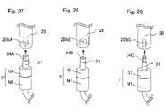
- Fig. 27 is a perspective view illustrating configurations of a power generating device 3 and a hinge component 2B according to a first modified embodiment of the second embodiment.
- the input shaft 31 of the power generating device 3 may have a triangular protrusion 34A
- the hinge component 2B may have a complementary triangular recess 2BbA.
- Fig. 28 is a perspective view illustrating configurations of a power generating device 3 and a hinge component 2B according to a second modified embodiment of the second embodiment.
- the input shaft 31 of the power generating device 3 may have a quadrangular protrusion 34B, and the hinge component 2B may have a complementary quadrangular recess 2BbB.
- Fig. 29 is a perspective view illustrating configurations of a power generating device 3 and a hinge component 2B according to a third modified embodiment of the second embodiment.
- the input shaft 31 of the power generating device 3 may have a cross-shaped protrusion 34C
- the hinge component 2B may have a complementary cross-shaped recess 2BbC.
- the input shaft 31 of the power generating device 3 may have a recess of some shape and the recess 2Bb of the hinge component 2B may have a protrusion of a complementary shape.
- the hinge devices according to the second embodiment are characterized by the following configurations.
- the input shaft of the power generating device 3 and the recess of the hinge component 2B may be shaped complementary to each other as seen from the point on the reference axis.
- the input shaft 31 of the power generating device 3 rotates by as much as rotation of the second hinge component 2B when the second hinge component 2B rotates about the reference axis.
- the protrusion 34 of the power generating device 3 and the recess 2Bb of the hinge component 2B being shaped complementary to each other, do not have to restrain the input shaft 31 of the power generating device 3 to the hinge component 2B with respect to the longitudinal direction of the reference axis. Accordingly, when the hinge components 1B1 and 1B12 support the hinge component 2B, the weight of the hinge component 2B is not applied to the power generating device 3. Therefore, it is possible to reliably operate the power generating device 3, without applying an extra mechanical load to the power generating device 3.
- the hinge components 1B1 and 1B2 may include the first portion (hinge component 1B1) and the second portion (hinge component 1B2).
- the hinge component 2B has the first and second ends along the reference axis, and the hinge component 2B is engaged with the hinge component 1B1 at the first end, and engaged with the hinge component 1B2 at the second end.
- the hinge components 1B1 and 1B2 are coupled to each other.
- the hinge device 10B it is possible to easily build, for example, a door including a stationary object and a movable object.
- the power generating device 3 may be provided in the hinge component 1B2.
- the first and second embodiments may be combined with each other.
- the tip of the input shaft 31 of the power generating device 3 and the recess 2a of the hinge component 2 may be shaped complementary to each other, instead of the dent 32 and the screw 41.
- the input shaft 31 of the power generating device 3 may be restrained to the hinge component 2B by a screw 41 penetrating the hinge component 2B.
- Various methods for restraining the input shaft 31 of the power generating device 3 to the hinge component 2B can be selected according to usage and size.
- the hinge component 1 may have a recess to be engaged with the hinge component 2, and the hinge component 2 may have a protrusion to be engaged with the hinge component 1.
- at least one of the hinge components 1B1 and 1B2 may have a protrusion to be engaged with the hinge component 2B, and the hinge component 2B may have a corresponding recess.
- the capacitors of the power storage circuit 12 have small capacitance, the battery is fully charged in a moment, and part of the generated electric power may be wasted. In addition, if the capacitors of the power storage circuit 12 have large capacitance, their size and cost increase. For a power generation system provided with the power generating device 3, the rectifier circuit 11, and the power storage circuit 12, it is an important issue to determine the capacitance of the capacitors of the power storage circuit 12 in consideration of various requirements. Accordingly, it is required to easily determine the optimal or nearly optimal capacitance of capacitors, and to provide a power system provided with such capacitors.
- a power system is provided, the power system being provided with capacitors having capacitance determined so as to reduce waste in generated electric power, without excessively increased size and cost.
- the power generating device 3 can generate a voltage as large as possible, when mechanical energy is inputted at a small angular velocity as slow as possible. Accordingly, hereinafter, we will illustrate a case of using a combination of a gear mechanism G1 having a high increasing gear ratio, and a power generator M1 having a high rated output voltage.
- the counter electromotive voltage constant Ked is an important indicator indicating the voltage across the output terminals of the power generating device 3, with respect to the rotational speed of the input shaft of the power generating device 3. As the counter electromotive voltage constant Ked becomes larger, a larger voltage output can be obtained from slow rotation.
- the SI units International System of Units
- Nda 28 (rpm) of the output shaft of the gear mechanism, when no load is applied, into SI units, the rotational angular velocity ⁇ da (rad/s) is obtained as follows.
- rotational torque Td is applied to the input shaft of the gear mechanism.
- the corresponding rotational angular velocity cod (rad/s) is obtained from the duration "t" (s) and the rotational angle ⁇ d d (degree) of the single opening or closing action of the door.
- ⁇ d (rad/s) is obtained as follows.
- the voltage generated at the output terminals of the power generating device 3 (speed electromotive force) is 12.86 (V).
- Fig. 30 is a schematic diagram for illustrating operations of the four capacitors C1 to C4 in the power system according to the third embodiment.
- voltage-doubling rectification is applied to voltage generated by the two power generators M1 and M2, and the capacitors C1 to C4 to be charged with voltage generated by the power generators M1 and M2 are cascaded with each other.
- E m1 and E m2 denote output voltages of the power generators M1 and M2, respectively.
- R m1 " and “R m2” denote resistances of winding of the power generators M1 and M2, respectively.
- C 1 " to “C 4” denote capacitances of the capacitors C1 to C4, respectively.
- V 1 " to “V 4” denote voltages stored in the capacitors C1 to C4, respectively.
- V 0 denotes a voltage across the four cascaded capacitors C1 to C4.
- each of waveforms of the voltages E m1 and E m2 represents a rectangular wave (AC voltage waveform) generated from the opening and closing actions of the door.
- the waveform of the voltage V 0 indicates the change over time in the stored voltage, depending on time constants of the resistances R m1 and R m2 and the capacitances C 1 to C 4 .
- the energy stored in the capacitors C1 to C4 is not completely consumed until the voltage across the capacitors C1 to C4 becomes zero, but supplying electric power from the power storage circuit 12 to the load device 14 is stopped when the voltage of one capacitor drops to a predetermined threshold voltage V 01 (V). Accordingly, when charging one capacitor, a state of the lower limit voltage (initial voltage) V 01 (V), and a state of the voltage V 1 at the end of the door opening/closing action are repeated.
- Fig. 31 is a schematic diagram for illustrating operation of one capacitor C1 in the power system according to the third embodiment. Referring to Fig. 31 , we analyze the operation of storing electric power generated by one power generator M1 when opening the door, in one capacitor C1. In the embodiment, this operation serves as a building block, and when the door is opened and closed only once in the electric power system including two power generators M1 and M2, a stored energy four times that of the building block operation is obtained.
- V 1 (V) across the capacitor C1 is obtained as follows.
- V 1 V 01 + E m 1 ⁇ V 01 1 ⁇ e ⁇ t / ⁇ 1
- V 01 (V) denotes the lower limit voltage of the capacitor C1, as described above.
- W E1M (J) the maximum energy W E1M (J) to be stored in the capacitor C1 is obtained as follows.
- W E 1 M 1 2 C 1 V 1 2
- the available energy W E1 (J) to be supplied from the capacitor C1 to the load device 14 is obtained as follows.
- V 1 10.712 (V).
- W E1M 0.5738 (J).
- W E1 0.5625 (J).
- the available energy W EE is, for example, 2.25 (J).
- the power system according to the embodiment can generate electric power exceeding 1 (W) and 1 (J).
- Fig. 32 is a graph showing characteristics of available energy to capacitance of a power system according to a first implementation example of the third embodiment.
- Fig. 33 is a graph showing characteristics of available energy to capacitance of a power system according to a second implementation example of the third embodiment.
- the characteristics of available energy to capacitance were calculated as shown in Figs. 32 and 33 , the characteristics being calculated as an upper limit available energy to be stored in the capacitors C1 to C4, with respect to the capacitance of each of the capacitors C1 to C4.
- Figs. 32 and 33 it can be seen that even when increasing the capacitances of the capacitors C1 to C4, the available energy reaches the upper limit at a certain capacitance. In addition, in the case of Fig. 32 , it can be clearly seen that the available energy has a peak value. Comparing Figs. 32 and 33 with each other, the available energy reaches the maximum at the capacitance of about 15 mF. The existence of this maximum can be explained by the fact that the output voltages E m1 and E m1 of the power generating devices are the same in cases of Figs. 32 and 33 , and the fact that the windings of the power generators M1 and M2 have resistances R m1 and R m2 , respectively.
- the available energy reaches the peak value at the capacitance of about 15 mF. Therefore, it can be seen that even when using capacitors having larger capacitances, their size and cost adversely increase.
- the capacitances of the capacitors C1 to C4 are gradually increased, and then, when the available energy approaches the peak value, the corresponding capacitance Cp is determined as the energy-maximizing capacitance.
- the power system of the embodiment of the present disclosure it can be seen that when selecting the energy-maximizing capacitance Cp as a design value, it is possible to achieve the maximum or nearly maximum performance with small size and low cost.
- the capacitances of the capacitors C1 to C4 are not necessarily strictly identical to the peak available energy.
- a capacitance may be selected from a range of capacitance corresponding to 80% (20% lower) to 90% (10% lower) of the strict peak available energy based on experiment.
- the range of capacitance is from a capacitance Cps1 lower than the energy-maximizing capacitance Cp, to a capacitance Cps2 higher than the energy-maximizing capacitance Cp, the energy-maximizing capacitance Cp corresponding to the strict peak available energy.
- the reason for selecting the capacitances Cps 1 and Cps2 corresponding to 80% to 90% of the peak available energy is to consider the range of variations of typical components.
- a capacitance may be selected from a range of capacitance, having a lower limit capacitance Cps1 corresponding to an available energy between 80% (20% lower) to 90% (10% lower) of the peak available energy (capacitance lower than the energy-maximizing capacitance Cp), and an upper limit capacitance Cp2 twice the energy-maximizing capacitance Cp.
- the reason for setting the upper limit twice the energy-maximizing capacitance Cp is that the capacitors' size is nearly doubled and their cost also increases accordingly, and it is considered that a capacitance up to twice the energy-maximizing capacitance Cp is acceptable as a small and inexpensive power system.
- the characteristics of available energy to capacitance indicating the upper limit available energy to be stored in the power storage circuit 12, with respect to the capacitance of the power storage circuit 12.
- the characteristics of energy to capacitance may be calculated, indicating an upper limit energy to be stored in the power storage circuit 12, with respect to the capacitance of the power storage circuit 12.
- a capacitance equal to or near the energy-maximizing capacitance can be set as the capacitance of the power storage circuit 12, the energy-maximizing capacitance indicating the capacitance maximizing the upper limit energy in the characteristics of energy to capacitance.
- the power generation systems and the power systems according to the third embodiment are characterized by the following configurations.
- the power generation system is provided with: at least one power generating device 3 that generates electric power by rotation of the input shaft 31; and the power storage circuit 12 including at least one capacitor C1 to C4, that stores the energy of the electric power generated by the power generating device 3.
- the power storage circuit 12 has a capacitance equal to or near the energy-maximizing capacitance, the energy-maximizing capacitance indicating a capacitance maximizing the upper limit energy in the characteristics of energy to capacitance, the characteristics being calculated as the upper limit energy to be stored in the power storage circuit 12, with respect to the capacitance of the power storage circuit 12.
- the characteristics of energy to capacitance are calculated based on: the capacitance of the power storage circuit 12, the electromotive force of the power generating device 3, the internal resistance of the power generating device 3, and the duration of one power generating action of the power generating device 3.
- the power storage circuit 12 may have a capacitance within a range of capacitance corresponding to a range of energy whose upper limit is equal to or greater than a predetermined value near the maximum energy in the characteristics of energy to capacitance.
- the power storage circuit 12 may have a capacitance within a range of capacitance corresponding to a range of energy whose upper limit is equal to or greater than a predetermined value between 80% to 90% of the maximum energy in the characteristics of energy to capacitance.
- the power storage circuit 12 may have a capacitance within a range of capacitance corresponding to a range of energy whose upper limit is equal to or greater than a predetermined value near the maximum energy in the characteristics of energy to capacitance, the range of capacitance having a lower limit capacitance smaller than the energy-maximizing capacitance, and an upper limit capacitance obtained by multiplying the energy-maximizing capacitance by a factor larger than one.
- the power storage circuit 12 may have a capacitance within a range of capacitance corresponding to a range of energy whose upper limit is equal to or greater than a predetermined value between 80% to 90% of the maximum energy in the characteristics of energy to capacitance, the range of capacitance having a lower limit capacitance smaller than the energy-maximizing capacitance, and an upper limit capacitance twice the energy-maximizing capacitance.
- C 1 denotes the capacitance of the capacitor C 1 of the power storage circuit 12
- Voi denotes the lower limit voltage of the capacitor C1
- E m1 denotes the electromotive force of the power generating device 3
- t denotes the duration of one power generating action of the power generating device 3
- ⁇ 1 denotes the time constant, based on the capacitance C 1 of the capacitor C1, and the internal resistance of the power generating device 3.
- the power generating device 3 may be provided with: the gear mechanism G1 that transmits rotation of the input shaft 31 of the power generating device 3 at the increasing gear ratio; and the power generator M1 that generates electric power by rotation transmitted by the gear mechanism G1.
- the power generation system may be provided with the plurality of power generating devices 3 cascaded with each other.
- the power generation system may be further provided with the rectifier circuit 11 that rectifies the electric power generated by the power generating device 3.
- the power storage circuit 12 stores energy of the electric power generated by the power generating device 3 and rectified by the rectifier circuit 11.
- the power storage circuit 12 may include the plurality of capacitors C1 to C4.
- the rectifier circuit 11 includes the voltage-doubling rectifier circuit.
- the power generation system may be further provided with the hinge device 10 provided with the first hinge component 1 and the second hinge component 2 having the common reference axis.
- the first hinge component 1 and the second hinge component 2 are engaged with each other, so as to be rotatable about the reference axis relative to each other, and so that one of the first hinge component 1 and the second hinge component 2 supports the other.
- the housing 30 of the power generating device 3 is fixed to the first hinge component 1, so that the input shaft 31 of the power generating device 3 is positioned on the reference axis.
- the input shaft 31 of the power generating device 3 is restrained to the second hinge component 2 with respect to the direction of rotation about the reference axis, so that the input shaft 31 of the power generating device 3 rotates by as much as rotation of the second hinge component 2 when the second hinge component 2 rotates about the reference axis.
- the hinge device 10 provided with the power generating device 3, the hinge device 10 being capable of efficiently extracting energy from the user's living activities to generate electric power.
- the power system is provided with: the power generation system; the controller circuit 13 that controls discharging of the power storage circuit 12 of the power generation system; and the load device 14 that consumes the electric power of the power storage circuit 12 under control of the controller circuit 13.
- the controller circuit 13 may supply electric power from the power storage circuit 12 to the load device 14, simultaneously with power generating action of the power generating device 3, or after the predetermined time has elapsed from the power generating action of the power generating device 3, or independently of the power generating action of the power generating device 3.
- the controller circuit 13 may stop supplying electric power from the power storage circuit 12 to the load device 14, when the voltage across the capacitors C1 to C4 of the power storage circuit 12 is equal to or lower than the predetermined lower limit voltage.
- the load device 14 may include a lighting device.
- the power system including the lighting device can be utilized for purposes of, e.g., lighting, warning to a suspicious person, and/or prevention of entry of a suspicious person.
- the load device 14 may include a communication device.
- the power system including the communication device can be utilized for purposes of, e.g., watching an elderly person and/or notification of a suspicious person.
Landscapes
- Engineering & Computer Science (AREA)
- Power Engineering (AREA)
- Mechanical Engineering (AREA)
- General Engineering & Computer Science (AREA)
- Charge And Discharge Circuits For Batteries Or The Like (AREA)
- Connection Of Motors, Electrical Generators, Mechanical Devices, And The Like (AREA)
Applications Claiming Priority (2)
| Application Number | Priority Date | Filing Date | Title |
|---|---|---|---|
| JP2017137357 | 2017-07-13 | ||
| PCT/JP2018/020990 WO2019012845A1 (ja) | 2017-07-13 | 2018-05-31 | 発電システム及び電力システム |
Publications (3)
| Publication Number | Publication Date |
|---|---|
| EP3654486A4 EP3654486A4 (en) | 2020-05-20 |
| EP3654486A1 EP3654486A1 (en) | 2020-05-20 |
| EP3654486B1 true EP3654486B1 (en) | 2023-03-08 |
Family
ID=65002139
Family Applications (1)
| Application Number | Title | Priority Date | Filing Date |
|---|---|---|---|
| EP18832701.9A Active EP3654486B1 (en) | 2017-07-13 | 2018-05-31 | Power generation system and electric power system |
Country Status (5)
| Country | Link |
|---|---|
| US (1) | US11139717B2 (ja) |
| EP (1) | EP3654486B1 (ja) |
| JP (1) | JP6948652B2 (ja) |
| CN (1) | CN110915096B (ja) |
| WO (1) | WO2019012845A1 (ja) |
Citations (1)
| Publication number | Priority date | Publication date | Assignee | Title |
|---|---|---|---|---|
| JP3960557B1 (ja) * | 2006-11-02 | 2007-08-15 | 株式会社パワーシステム | 電気車両のハイブリッド蓄電装置及び電気車両 |
Family Cites Families (28)
| Publication number | Priority date | Publication date | Assignee | Title |
|---|---|---|---|---|
| JP3331529B2 (ja) | 1993-01-29 | 2002-10-07 | キヤノン株式会社 | 蓄電装置及び電力システム |
| JPH06343225A (ja) * | 1993-05-28 | 1994-12-13 | Asahi Glass Co Ltd | 蓄電電源装置 |
| JP2000130005A (ja) | 1998-10-26 | 2000-05-09 | Seiko Epson Corp | ドアクローザー |
| JP2001112178A (ja) * | 1999-10-01 | 2001-04-20 | Mitsubishi Heavy Ind Ltd | 発電システム |
| JP2001231234A (ja) | 2000-02-10 | 2001-08-24 | Hyper Electronics:Kk | 携帯用発電機 |
| JP2002084795A (ja) | 2000-09-01 | 2002-03-22 | Shinko Electric Co Ltd | 発電装置 |
| JP3915577B2 (ja) | 2002-04-05 | 2007-05-16 | 松下電工株式会社 | 開閉検知センサ |
| JP2004204533A (ja) * | 2002-12-25 | 2004-07-22 | Mitsubishi Electric Engineering Co Ltd | 扉開閉装置 |
| JP4797488B2 (ja) * | 2005-07-26 | 2011-10-19 | パナソニック株式会社 | 車両用電源装置 |
| DE202006009731U1 (de) | 2006-06-22 | 2006-09-07 | Christoph Langenhorst Gmbh | Energieerzeugungseinrichtung |
| US7795746B2 (en) * | 2008-05-01 | 2010-09-14 | Robert Bosch Gmbh | Apparatus and method for generating power for a low current device |
| TW201001350A (en) | 2008-06-20 | 2010-01-01 | Hsuan-Chang Chiang | On-door indication apparatus and method with self power generation |
| CN102470812B (zh) * | 2009-07-24 | 2014-07-23 | 三菱电机株式会社 | 车辆用电源系统 |
| JP5491169B2 (ja) * | 2009-12-29 | 2014-05-14 | 旭化成株式会社 | 電源供給システムおよび電源供給システムを備える携帯機器、ならびに電源供給システムの充電方法、電源供給システムの放電方法および電源供給システムの充放電方法 |
| US8816537B2 (en) | 2010-01-18 | 2014-08-26 | Toyota Jidosha Kabushiki Kaisha | Contactless electric power receiving apparatus, contactless electric power transmitting apparatus, contactless electric power feeding system, and vehicle |
| JP5302913B2 (ja) | 2010-02-18 | 2013-10-02 | 八千代工業株式会社 | 扉発電装置 |
| EP2378041B1 (en) | 2010-04-15 | 2017-01-04 | Hanchett Entry Systems, Inc. | Electric door release powered by an energy harvester |
| CN203289293U (zh) * | 2010-10-22 | 2013-11-13 | 日本电产株式会社 | 发电机 |
| JP2013070520A (ja) | 2011-09-22 | 2013-04-18 | Panasonic Corp | 非接触給電装置の駆動方法、非接触給電装置及び非接触給電システム |
| JP2013155495A (ja) | 2012-01-27 | 2013-08-15 | Nhk Spring Co Ltd | ドアクローザ |
| JP6012971B2 (ja) * | 2012-01-30 | 2016-10-25 | 株式会社ブラザーエンタープライズ | スライド扉用発電装置、およびスライド扉用作動装置 |
| JP5849897B2 (ja) * | 2012-08-22 | 2016-02-03 | トヨタ自動車株式会社 | 電池管理システムおよび電池の交換方法 |
| JP6144484B2 (ja) | 2012-12-18 | 2017-06-07 | キヤノンプレシジョン株式会社 | ドアクローザ |
| KR102082866B1 (ko) * | 2013-04-18 | 2020-04-14 | 삼성에스디아이 주식회사 | 배터리 관리 시스템 및 그 구동방법 |
| JP2015001126A (ja) | 2013-06-17 | 2015-01-05 | 日本発條株式会社 | 制動装置及びドアクローザ |
| CN203734323U (zh) * | 2014-03-20 | 2014-07-23 | 大英聚能科技发展有限公司 | 超级电容电池智能错峰储电供电器 |
| CN105940161B (zh) * | 2014-03-31 | 2019-02-12 | 住友建机株式会社 | 挖土机 |
| JP6686704B2 (ja) * | 2016-05-31 | 2020-04-22 | 株式会社デンソー | 制御装置 |
-
2018
- 2018-05-31 EP EP18832701.9A patent/EP3654486B1/en active Active
- 2018-05-31 JP JP2019528977A patent/JP6948652B2/ja active Active
- 2018-05-31 US US16/628,429 patent/US11139717B2/en active Active
- 2018-05-31 WO PCT/JP2018/020990 patent/WO2019012845A1/ja unknown
- 2018-05-31 CN CN201880046259.6A patent/CN110915096B/zh active Active
Patent Citations (1)
| Publication number | Priority date | Publication date | Assignee | Title |
|---|---|---|---|---|
| JP3960557B1 (ja) * | 2006-11-02 | 2007-08-15 | 株式会社パワーシステム | 電気車両のハイブリッド蓄電装置及び電気車両 |
Also Published As
| Publication number | Publication date |
|---|---|
| WO2019012845A1 (ja) | 2019-01-17 |
| US20200161935A1 (en) | 2020-05-21 |
| JPWO2019012845A1 (ja) | 2020-04-16 |
| CN110915096A (zh) | 2020-03-24 |
| EP3654486A4 (en) | 2020-05-20 |
| US11139717B2 (en) | 2021-10-05 |
| JP6948652B2 (ja) | 2021-10-13 |
| CN110915096B (zh) | 2023-04-21 |
| EP3654486A1 (en) | 2020-05-20 |
Similar Documents
| Publication | Publication Date | Title |
|---|---|---|
| US11211847B2 (en) | Hinge device provided with power generating device and capable of extracting energy from user's living activities to generate electric power | |
| EP1562281B1 (en) | Wind power generator | |
| US8093731B2 (en) | Gearless human power generation | |
| US20080157636A1 (en) | Human power generation using dual pulls | |
| EP0862262A2 (en) | Power generating device, charging method and timepiece | |
| US7876065B2 (en) | Method for extending the time a portable generator powered by a DC battery may operate by recharging the battery at the same time it is being used as a power source | |
| US20080150378A1 (en) | Human power generation using a pulley | |
| EP2527606A2 (en) | Closed energy combined cycle system and operation method thereof | |
| US9515516B2 (en) | Portable power station system | |
| EP3654486B1 (en) | Power generation system and electric power system | |
| CN113037129A (zh) | 摩擦纳米发电机及基于其的自驱动智能测速仪 | |
| US20110019447A1 (en) | Solar motor generator power converter | |
| US9812927B2 (en) | Electro-mechanical dynamo for C and D battery replacement | |
| JP2001019310A (ja) | エレベータ | |
| Abilash et al. | IoT Based Solar Power Monitoring System | |
| Nahale et al. | Electricity Generation by Human Efforts in Swing and Mobile Charging System | |
| US11165274B1 (en) | Portable, motor-driven alternator for use in recharging a battery | |
| Vignesh et al. | Design and analysis of door harvesting energy | |
| CN215956291U (zh) | 摩擦纳米发电机及基于其的自驱动智能测速仪 | |
| JP3217337U (ja) | 独立電源を提供可能な蓄電ユニット及び当該蓄電ユニットを備えた倉庫、物置、ガレージ又はカーポート | |
| KR200312426Y1 (ko) | 풍력을 이용한 자동 밧데리 충전기 | |
| RU1192U1 (ru) | Фотовспышка с электродинамическим источником питания | |
| KR20020038669A (ko) | 리모콘용 자가발전 전원공급장치 | |
| Lund | Rotor Powered Battery Charger | |
| KR19980073970A (ko) | 충전식 배터리팩의 자기충전장치 |
Legal Events
| Date | Code | Title | Description |
|---|---|---|---|
| STAA | Information on the status of an ep patent application or granted ep patent |
Free format text: STATUS: THE INTERNATIONAL PUBLICATION HAS BEEN MADE |
|
| PUAI | Public reference made under article 153(3) epc to a published international application that has entered the european phase |
Free format text: ORIGINAL CODE: 0009012 |
|
| STAA | Information on the status of an ep patent application or granted ep patent |
Free format text: STATUS: REQUEST FOR EXAMINATION WAS MADE |
|
| 17P | Request for examination filed |
Effective date: 20200107 |
|
| A4 | Supplementary search report drawn up and despatched |
Effective date: 20200312 |
|
| AK | Designated contracting states |
Kind code of ref document: A1 Designated state(s): AL AT BE BG CH CY CZ DE DK EE ES FI FR GB GR HR HU IE IS IT LI LT LU LV MC MK MT NL NO PL PT RO RS SE SI SK SM TR |
|
| AX | Request for extension of the european patent |
Extension state: BA ME |
|
| DAV | Request for validation of the european patent (deleted) | ||
| DAX | Request for extension of the european patent (deleted) | ||
| STAA | Information on the status of an ep patent application or granted ep patent |
Free format text: STATUS: EXAMINATION IS IN PROGRESS |
|
| 17Q | First examination report despatched |
Effective date: 20210421 |
|
| REG | Reference to a national code |
Ref country code: DE Ref legal event code: R079 Ref document number: 602018047071 Country of ref document: DE Free format text: PREVIOUS MAIN CLASS: H02J0007000000 Ipc: H02J0007340000 |
|
| GRAP | Despatch of communication of intention to grant a patent |
Free format text: ORIGINAL CODE: EPIDOSNIGR1 |
|
| STAA | Information on the status of an ep patent application or granted ep patent |
Free format text: STATUS: GRANT OF PATENT IS INTENDED |
|
| RIC1 | Information provided on ipc code assigned before grant |
Ipc: H02J 50/00 20160101ALN20221018BHEP Ipc: H02K 7/18 20060101ALI20221018BHEP Ipc: F16C 11/04 20060101ALI20221018BHEP Ipc: E05D 11/00 20060101ALI20221018BHEP Ipc: H02J 7/14 20060101ALI20221018BHEP Ipc: H02J 7/34 20060101AFI20221018BHEP |
|
| INTG | Intention to grant announced |
Effective date: 20221104 |
|
| RIC1 | Information provided on ipc code assigned before grant |
Ipc: H02J 50/00 20160101ALN20221021BHEP Ipc: H02K 7/18 20060101ALI20221021BHEP Ipc: F16C 11/04 20060101ALI20221021BHEP Ipc: E05D 11/00 20060101ALI20221021BHEP Ipc: H02J 7/14 20060101ALI20221021BHEP Ipc: H02J 7/34 20060101AFI20221021BHEP |
|
| GRAS | Grant fee paid |
Free format text: ORIGINAL CODE: EPIDOSNIGR3 |
|
| GRAA | (expected) grant |
Free format text: ORIGINAL CODE: 0009210 |
|
| STAA | Information on the status of an ep patent application or granted ep patent |
Free format text: STATUS: THE PATENT HAS BEEN GRANTED |
|
| AK | Designated contracting states |
Kind code of ref document: B1 Designated state(s): AL AT BE BG CH CY CZ DE DK EE ES FI FR GB GR HR HU IE IS IT LI LT LU LV MC MK MT NL NO PL PT RO RS SE SI SK SM TR |
|
| REG | Reference to a national code |
Ref country code: CH Ref legal event code: EP Ref country code: AT Ref legal event code: REF Ref document number: 1553248 Country of ref document: AT Kind code of ref document: T Effective date: 20230315 |
|
| REG | Reference to a national code |
Ref country code: IE Ref legal event code: FG4D |
|
| REG | Reference to a national code |
Ref country code: DE Ref legal event code: R096 Ref document number: 602018047071 Country of ref document: DE |
|
| REG | Reference to a national code |
Ref country code: LT Ref legal event code: MG9D |
|
| REG | Reference to a national code |
Ref country code: NL Ref legal event code: MP Effective date: 20230308 |
|
| PG25 | Lapsed in a contracting state [announced via postgrant information from national office to epo] |
Ref country code: RS Free format text: LAPSE BECAUSE OF FAILURE TO SUBMIT A TRANSLATION OF THE DESCRIPTION OR TO PAY THE FEE WITHIN THE PRESCRIBED TIME-LIMIT Effective date: 20230308 Ref country code: NO Free format text: LAPSE BECAUSE OF FAILURE TO SUBMIT A TRANSLATION OF THE DESCRIPTION OR TO PAY THE FEE WITHIN THE PRESCRIBED TIME-LIMIT Effective date: 20230608 Ref country code: LV Free format text: LAPSE BECAUSE OF FAILURE TO SUBMIT A TRANSLATION OF THE DESCRIPTION OR TO PAY THE FEE WITHIN THE PRESCRIBED TIME-LIMIT Effective date: 20230308 Ref country code: LT Free format text: LAPSE BECAUSE OF FAILURE TO SUBMIT A TRANSLATION OF THE DESCRIPTION OR TO PAY THE FEE WITHIN THE PRESCRIBED TIME-LIMIT Effective date: 20230308 Ref country code: HR Free format text: LAPSE BECAUSE OF FAILURE TO SUBMIT A TRANSLATION OF THE DESCRIPTION OR TO PAY THE FEE WITHIN THE PRESCRIBED TIME-LIMIT Effective date: 20230308 Ref country code: ES Free format text: LAPSE BECAUSE OF FAILURE TO SUBMIT A TRANSLATION OF THE DESCRIPTION OR TO PAY THE FEE WITHIN THE PRESCRIBED TIME-LIMIT Effective date: 20230308 |
|
| REG | Reference to a national code |
Ref country code: AT Ref legal event code: MK05 Ref document number: 1553248 Country of ref document: AT Kind code of ref document: T Effective date: 20230308 |
|
| PG25 | Lapsed in a contracting state [announced via postgrant information from national office to epo] |
Ref country code: SE Free format text: LAPSE BECAUSE OF FAILURE TO SUBMIT A TRANSLATION OF THE DESCRIPTION OR TO PAY THE FEE WITHIN THE PRESCRIBED TIME-LIMIT Effective date: 20230308 Ref country code: NL Free format text: LAPSE BECAUSE OF FAILURE TO SUBMIT A TRANSLATION OF THE DESCRIPTION OR TO PAY THE FEE WITHIN THE PRESCRIBED TIME-LIMIT Effective date: 20230308 Ref country code: GR Free format text: LAPSE BECAUSE OF FAILURE TO SUBMIT A TRANSLATION OF THE DESCRIPTION OR TO PAY THE FEE WITHIN THE PRESCRIBED TIME-LIMIT Effective date: 20230609 Ref country code: FI Free format text: LAPSE BECAUSE OF FAILURE TO SUBMIT A TRANSLATION OF THE DESCRIPTION OR TO PAY THE FEE WITHIN THE PRESCRIBED TIME-LIMIT Effective date: 20230308 |
|
| PG25 | Lapsed in a contracting state [announced via postgrant information from national office to epo] |
Ref country code: SM Free format text: LAPSE BECAUSE OF FAILURE TO SUBMIT A TRANSLATION OF THE DESCRIPTION OR TO PAY THE FEE WITHIN THE PRESCRIBED TIME-LIMIT Effective date: 20230308 Ref country code: RO Free format text: LAPSE BECAUSE OF FAILURE TO SUBMIT A TRANSLATION OF THE DESCRIPTION OR TO PAY THE FEE WITHIN THE PRESCRIBED TIME-LIMIT Effective date: 20230308 Ref country code: PT Free format text: LAPSE BECAUSE OF FAILURE TO SUBMIT A TRANSLATION OF THE DESCRIPTION OR TO PAY THE FEE WITHIN THE PRESCRIBED TIME-LIMIT Effective date: 20230710 Ref country code: EE Free format text: LAPSE BECAUSE OF FAILURE TO SUBMIT A TRANSLATION OF THE DESCRIPTION OR TO PAY THE FEE WITHIN THE PRESCRIBED TIME-LIMIT Effective date: 20230308 Ref country code: CZ Free format text: LAPSE BECAUSE OF FAILURE TO SUBMIT A TRANSLATION OF THE DESCRIPTION OR TO PAY THE FEE WITHIN THE PRESCRIBED TIME-LIMIT Effective date: 20230308 Ref country code: AT Free format text: LAPSE BECAUSE OF FAILURE TO SUBMIT A TRANSLATION OF THE DESCRIPTION OR TO PAY THE FEE WITHIN THE PRESCRIBED TIME-LIMIT Effective date: 20230308 |
|
| PG25 | Lapsed in a contracting state [announced via postgrant information from national office to epo] |
Ref country code: SK Free format text: LAPSE BECAUSE OF FAILURE TO SUBMIT A TRANSLATION OF THE DESCRIPTION OR TO PAY THE FEE WITHIN THE PRESCRIBED TIME-LIMIT Effective date: 20230308 Ref country code: PL Free format text: LAPSE BECAUSE OF FAILURE TO SUBMIT A TRANSLATION OF THE DESCRIPTION OR TO PAY THE FEE WITHIN THE PRESCRIBED TIME-LIMIT Effective date: 20230308 Ref country code: IS Free format text: LAPSE BECAUSE OF FAILURE TO SUBMIT A TRANSLATION OF THE DESCRIPTION OR TO PAY THE FEE WITHIN THE PRESCRIBED TIME-LIMIT Effective date: 20230708 |
|
| REG | Reference to a national code |
Ref country code: DE Ref legal event code: R097 Ref document number: 602018047071 Country of ref document: DE |
|
| REG | Reference to a national code |
Ref country code: CH Ref legal event code: PL |
|
| PLBE | No opposition filed within time limit |
Free format text: ORIGINAL CODE: 0009261 |
|
| STAA | Information on the status of an ep patent application or granted ep patent |
Free format text: STATUS: NO OPPOSITION FILED WITHIN TIME LIMIT |
|
| PG25 | Lapsed in a contracting state [announced via postgrant information from national office to epo] |
Ref country code: MC Free format text: LAPSE BECAUSE OF FAILURE TO SUBMIT A TRANSLATION OF THE DESCRIPTION OR TO PAY THE FEE WITHIN THE PRESCRIBED TIME-LIMIT Effective date: 20230308 |
|
| REG | Reference to a national code |
Ref country code: BE Ref legal event code: MM Effective date: 20230531 |
|
| PG25 | Lapsed in a contracting state [announced via postgrant information from national office to epo] |
Ref country code: SI Free format text: LAPSE BECAUSE OF FAILURE TO SUBMIT A TRANSLATION OF THE DESCRIPTION OR TO PAY THE FEE WITHIN THE PRESCRIBED TIME-LIMIT Effective date: 20230308 Ref country code: MC Free format text: LAPSE BECAUSE OF FAILURE TO SUBMIT A TRANSLATION OF THE DESCRIPTION OR TO PAY THE FEE WITHIN THE PRESCRIBED TIME-LIMIT Effective date: 20230308 Ref country code: LU Free format text: LAPSE BECAUSE OF NON-PAYMENT OF DUE FEES Effective date: 20230531 Ref country code: LI Free format text: LAPSE BECAUSE OF NON-PAYMENT OF DUE FEES Effective date: 20230531 Ref country code: DK Free format text: LAPSE BECAUSE OF FAILURE TO SUBMIT A TRANSLATION OF THE DESCRIPTION OR TO PAY THE FEE WITHIN THE PRESCRIBED TIME-LIMIT Effective date: 20230308 Ref country code: CH Free format text: LAPSE BECAUSE OF NON-PAYMENT OF DUE FEES Effective date: 20230531 |
|
| 26N | No opposition filed |
Effective date: 20231211 |
|
| GBPC | Gb: european patent ceased through non-payment of renewal fee |
Effective date: 20230608 |
|
| REG | Reference to a national code |
Ref country code: IE Ref legal event code: MM4A |
|
| PG25 | Lapsed in a contracting state [announced via postgrant information from national office to epo] |
Ref country code: IE Free format text: LAPSE BECAUSE OF NON-PAYMENT OF DUE FEES Effective date: 20230531 |
|
| PG25 | Lapsed in a contracting state [announced via postgrant information from national office to epo] |
Ref country code: IE Free format text: LAPSE BECAUSE OF NON-PAYMENT OF DUE FEES Effective date: 20230531 Ref country code: GB Free format text: LAPSE BECAUSE OF NON-PAYMENT OF DUE FEES Effective date: 20230608 |
|
| PG25 | Lapsed in a contracting state [announced via postgrant information from national office to epo] |
Ref country code: IT Free format text: LAPSE BECAUSE OF FAILURE TO SUBMIT A TRANSLATION OF THE DESCRIPTION OR TO PAY THE FEE WITHIN THE PRESCRIBED TIME-LIMIT Effective date: 20230308 Ref country code: FR Free format text: LAPSE BECAUSE OF NON-PAYMENT OF DUE FEES Effective date: 20230531 Ref country code: BE Free format text: LAPSE BECAUSE OF NON-PAYMENT OF DUE FEES Effective date: 20230531 |
|
| PGFP | Annual fee paid to national office [announced via postgrant information from national office to epo] |
Ref country code: DE Payment date: 20240521 Year of fee payment: 7 |