EP3653379A1 - Rakelkammerträger - Google Patents
Rakelkammerträger Download PDFInfo
- Publication number
- EP3653379A1 EP3653379A1 EP19210039.4A EP19210039A EP3653379A1 EP 3653379 A1 EP3653379 A1 EP 3653379A1 EP 19210039 A EP19210039 A EP 19210039A EP 3653379 A1 EP3653379 A1 EP 3653379A1
- Authority
- EP
- European Patent Office
- Prior art keywords
- doctor blade
- chamber
- doctor
- blade chamber
- carrier
- Prior art date
- Legal status (The legal status is an assumption and is not a legal conclusion. Google has not performed a legal analysis and makes no representation as to the accuracy of the status listed.)
- Granted
Links
Images


Classifications
-
- B—PERFORMING OPERATIONS; TRANSPORTING
- B41—PRINTING; LINING MACHINES; TYPEWRITERS; STAMPS
- B41F—PRINTING MACHINES OR PRESSES
- B41F31/00—Inking arrangements or devices
- B41F31/02—Ducts, containers, supply or metering devices
- B41F31/027—Ink rail devices for inking ink rollers
-
- B—PERFORMING OPERATIONS; TRANSPORTING
- B41—PRINTING; LINING MACHINES; TYPEWRITERS; STAMPS
- B41F—PRINTING MACHINES OR PRESSES
- B41F13/00—Common details of rotary presses or machines
- B41F13/0024—Frames
Definitions
- the invention relates to a doctor blade chamber carrier of a printing machine for fastening a doctor blade chamber, which cooperates with a metering roller in a printing operating position, and a corresponding method for fastening a doctor blade chamber to a doctor blade chamber carrier.
- the original system is the submersible roller inking unit (3-roller inking unit), which for example comes from DE 29 42 521 C2 is known.
- the ink is metered by squeezing the excess ink in the nip between the dip roller and anilox roller.
- the squeegee chamber system has therefore established itself as a further inking unit type, which offers the advantage of very easy-to-dose ink transfer with simultaneous repeatability.
- the open and the closed system With the squeegee chamber system, a distinction is again made between the open and the closed system, whereby the closed system has largely prevailed since it also enables automatic cleaning of the anilox rollers and all ink-carrying parts and thus fast and automatable job and ink changes.
- a closed doctor blade chamber system according to the prior art is known for example from US Pat EP1 302 315 B1 known.
- a remaining problem of such a doctor blade chamber system is, however, the fact that various measures have to be taken to ensure tightness, which entail constant and not negligible maintenance.
- those in the EP1 302 315 B1 mentioned face seals are regularly replaced and renewed to ensure the tightness of the closed doctor chamber system.
- the performance of maintenance work on a closed doctor blade chamber system is in turn impaired by the fact that the doctor blade chamber is difficult to access within the printing press. So the closed doctor chamber system comes according to the EP1 302 315 B1 usually used in a central cylinder printing machine, such as this from the WO 2009/144016 A1 is known. This means that typically 8 closed doctor blade chamber systems are arranged around the central cylinder. Since the central cylinder forms a sensitive core in every central cylinder printing machine, maintenance work on the doctor blade chamber systems in its vicinity may only be carried out with extreme caution and only by trained specialist personnel. This aspect also increases the costs for any maintenance work on the doctor blade chamber systems.
- the object of the invention is therefore to reduce the maintenance outlay of the inking units known in particular from the flexographic printing sector.
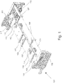
- Fig. 1 shows a perspective view of the doctor blade chamber carrier according to the invention.
- the doctor blade chamber carrier 101 has two side parts 102 and 103 which are connected to one another by a strut 104 and a holding plate 105.
- a plurality of guide rails 106, 107, 108, 109, 110 and 111 are provided on the upper side of the doctor blade chamber carrier 101, on which the attached doctor blade chamber can be moved.
- a cylinder 112 On the underside of the squeegee chamber carrier 101, a cylinder 112 is provided with which the two bolts 113 and 114 can be actuated. In addition to the bolts 113 and 114 there is a stop 115 and 116.
- nozzles 117 and 118 At the ends of the holding plate 105 there are in each case nozzles 117 and 118, with which a sealing connection to the ink circuit on the machine side can be produced in the printing operating position.
- Fig. 2 shows a perspective view of the doctor blade chamber carrier 101 from Fig. 1 with attached doctor chamber 201.
- the reference symbols of the doctor chamber carrier correspond to the reference symbols Fig. 1 , so refer to the explanations above Fig. 1 can be referred.
- With the directional arrow 202 Direction of displacement indicated, in which the attached doctor chamber 201 can be moved against the stops 115 and 116.
- Fig. 3 shows a perspective view of the doctor blade chamber carrier Fig. 2 with advanced doctor chamber.
- the reference symbols correspond to the reference symbols Fig. 1 and Fig. 2 , so refer to the explanations above Fig. 1 and Fig. 2 can be referred.
- the doctor chamber 201 is now displaced against the stops 114 and 115 and is fixed in the lateral direction by the guide rails 108, 109, 110 and 111.
- the squeegee chamber 201 is thus held in a form-fitting manner on the squeegee chamber carrier 101, with the exception of one degree of freedom, the one degree of freedom being capable of being acted upon by at least one switchable and reversible bolt in such a way that the bolt keeps the squeegee chamber at a distance from the squeegee chamber carrier or fixes it to the squeegee chamber carrier.
- the arrow 301 points to the visible distance that the doctor blade chamber 201 has when the bolts 113 and 114 are extended relative to the holding plate 105.
- Fig. 4 shows a perspective view of the doctor blade chamber carrier Fig. 3 with fixed squeegee chamber.
- the reference symbols correspond to the reference symbols Fig. 1 , Fig. 2 and Fig. 3 , so refer to the explanations above Fig. 1 , Fig. 2 and Fig. 3 can be referred.
- the difference between the state in Fig. 3 and the state in Fig. 4 now consists in that the bolts 113 and 114 were actuated downward, so that the doctor chamber 201 is thus fixed to the doctor chamber carrier 101.
- the arrow 401 shows that the doctor chamber 201 is now opposite the state in FIG Fig. 3 was lowered.
Landscapes
- Engineering & Computer Science (AREA)
- Mechanical Engineering (AREA)
- Inking, Control Or Cleaning Of Printing Machines (AREA)
Abstract
Description
- Die Erfindung betrifft einen Rakelkammerträger einer Druckmaschine zum Befestigen einer Rakelkammer, die in einer Druckbetriebsposition mit einer Dosierwalze zusammenwirkt, und ein entsprechendes Verfahren zum Befestigen einer Rakelkammer an einem Rakelkammerträger.
- Im Bereich des Flexodrucks sind grundsätzlich verschiedene Dosierwerke bzw. Farbwerkstypen bekannt, von denen das Rakelkammersystem einen Farbwerkstyp darstellt.
- Das ursprüngliche System ist das Tauchwalzenfarbwerk (3-Walzen-Farbwerk), das beispielsweise aus der
DE 29 42 521 C2 bekannt ist. Die Farbdosierung erfolgt über das Abquetschen der überflüssigen Farbe in dem Walzenspalt zwischen Tauchwalze und Rasterwalze. - Mit der zunehmenden Bedeutung des Rasterdrucks wurden allerdings immer höhere Anforderungen an die Druckqualität gestellt, die sich durch das vorgenannte Tauchwalzenfarbwerk nicht erfüllen lassen. Als weiterer Farbwerkstyp hat sich daher vor allem das Rakelkammersystem etabliert, das den Vorteil einer sehr gut dosierbaren Farbübertragung bei gleichzeitig beliebiger Wiederholbarkeit bietet. Beim Rakelkammersystem unterscheidet man wiederum zwischen dem offenen und dem geschlossenen System, wobei sich das geschlossene System inzwischen weitestgehend durchgesetzt hat, da hiermit auch eine automatische Reinigung der Rasterwalzen und aller farbführenden Teile und damit schnelle und automatisierbare Auftrags- und Farbwechsel möglich ist.
- Ein geschlossenes Rakelkammersystem nach dem Stand der Technik ist beispielsweise aus der
EP1 302 315 B1 bekannt. Ein verbleibendes Problem eines derartigen Rakelkammersystems ist allerdings die Tatsache, dass zur Gewährleistung der Dichtigkeit verschiedene Maßnahmen ergriffen müssen, die einen ständigen und nicht zu vernachlässigen Wartungsaufwand nach sich ziehen. So müssen beispielsweise die in derEP1 302 315 B1 erwähnten stirnseitigen Dichtungen regelmäßig ausgetauscht und erneuert werden, um die Dichtigkeit des geschlossenen Rakelkammersystems sicherzustellen. - Die Durchführung von Wartungsarbeiten an einem geschlossenen Rakelkammersystem wird wiederum dadurch beeinträchtigt, dass die Rakelkammer innerhalb der Druckmaschine nur schwer zugänglich ist. So kommt das geschlossene Rakelkammersystem gemäß der
EP1 302 315 B1 in der Regel in einer Zentralzylinderdruckmaschine zum Einsatz, wie diese beispielsweise aus derWO 2009/144016 A1 bekannt ist. Dies bedeutet, dass typischerweise 8 geschlossene Rakelkammersysteme um den Zentralzylinder herum angeordnet sind. Da der Zentralzylinder ein empfindliches Herzstück in jeder Zentralzylinderdruckmaschine bildet, dürfen in dessen Nähe Wartungsarbeiten an den Rakelkammersystemen nur mit äußerster Vorsicht und nur von geschultem Fachpersonal durchgeführt werden. Auch dieser Aspekt erhöht die Kosten für jegliche Wartungsarbeiten an den Rakelkammersystemen. - Aufgabe der Erfindung ist es daher, den Wartungsaufwand der insbesondere aus dem Flexodruckbereich bekannten Farbwerke zu reduzieren.
- Diese Aufgabe wird durch die Merkmale des Patentanspruchs 1 und des Patentanspruchs 3 gelöst. Bevorzugte Ausführungsformen sind durch die Unteransprüche 2 und 4 gegeben.
- Weitere Einzelheiten und Vorteile der Erfindung werden anhand der beigefügten Zeichnungen beschrieben:
- Fig. 1
- zeigt eine perspektivische Ansicht des erfindungsgemäßen Rakelkammerträgers.
- Fig. 2
- zeigt eine perspektivische Ansicht des Rakelkammerträgers aus
Fig. 1 mit aufgesetzter Rakelkammer. - Fig. 3
- zeigt eine perspektivische Ansicht des Rakelkammerträgers aus
Fig. 2 mit vorgeschobener Rakelkammer. - Fig. 4
- zeigt eine perspektivische Ansicht des Rakelkammerträgers aus
Fig. 3 mit fixierter Rakelkammer. -
Fig. 1 zeigt eine perspektivische Ansicht des erfindungsgemäßen Rakelkammerträgers. Seinem grundsätzlichen Aufbau nach weist der Rakelkammerträger 101 zwei Seitenteile 102 und 103 auf, die durch eine Strebe 104 und eine Halteplatte 105 miteinander verbunden sind. - An der Oberseite des Rakelkammerträgers 101 sind mehrere Führungsschienen 106, 107, 108, 109, 110 und 111 vorgesehen, auf denen die aufgesetzte Rakelkammer geführt verschoben werden kann.
- An der Unterseite des Rakelkammerträgers 101 ist ein Zylinder 112 vorgesehen, mit dem die beiden Bolzen 113 und 114 betätigt werden können. Neben den Bolzen 113 und 114 befindet sich jeweils ein Anschlag 115 und 116.
- An den Enden der Halteplatte 105 sind jeweils Stutzen 117 und 118 vorgesehen, mit denen in der Druckbetriebsposition ein dichtender Anschluss an den maschinenseitigen Farbkreislauf herstellbar ist.
-
Fig. 2 zeigt eine perspektivische Ansicht des Rakelkammerträgers 101 ausFig. 1 mit aufgesetzter Rakelkammer 201. Die Bezugszeichen des Rakelkammerträgers entsprechen den Bezugszeichen ausFig. 1 , sodass diesbezüglich auf die obigen Erläuterungen zuFig. 1 verwiesen werden kann. Mit dem Richtungspfeil 202 ist die Verschieberichtung angedeutet, in die die aufgesetzte Rakelkammer 201 gegen die Anschläge 115 und 116 verschoben werden kann. -
Fig. 3 zeigt eine perspektivische Ansicht des Rakelkammerträgers ausFig. 2 mit vorgeschobener Rakelkammer. Die Bezugszeichen entsprechen den Bezugszeichen ausFig. 1 undFig. 2 , sodass diesbezüglich auf die obigen Erläuterungen zuFig. 1 undFig. 2 verwiesen werden kann. In der gezeigten Position ist die Rakelkammer 201 nunmehr gegen die Anschläge 114 und 115 verschoben und wird in seitlicher Richtung durch die Führungsschienen 108, 109, 110 und 111 fixiert. Damit wird die Rakelkammer 201 formschlüssig am Rakelkammerträger 101 mit Ausnahme eines Freiheitsgrades gehalten, wobei der eine Freiheitsgrad mit mindestens einem schaltbaren und umkehrbaren Bolzen derart beaufschlagbar ist, dass der Bolzen die Rakelkammer wahlweise gegenüber dem Rakelkammerträger auf Abstand hält oder am Rakelkammerträger fixiert. Der Pfeil 301 zeigt auf den sichtbaren Abstand, den die Rakelkammer 201 bei ausgefahrenen Bolzen 113 und 114 gegenüber der Halteplatte 105 aufweist. -
Fig. 4 zeigt eine perspektivische Ansicht des Rakelkammerträgers ausFig. 3 mit fixierter Rakelkammer. Die Bezugszeichen entsprechen den Bezugszeichen ausFig. 1 ,Fig. 2 undFig. 3 , sodass diesbezüglich auf die obigen Erläuterungen zuFig. 1 ,Fig. 2 undFig. 3 verwiesen werden kann. Der Unterschied zwischen dem Zustand inFig. 3 und dem Zustand inFig. 4 besteht nunmehr darin, dass die Bolzen 113 und 114 nach unten betätigt wurden, sodass die Rakelkammer 201 damit am Rakelkammerträger 101 fixiert ist. Der Pfeil 401 zeigt, dass nunmehr die Rakelkammer 201 gegenüber dem Zustand inFig. 3 abgesenkt wurde.
Claims (4)
- Rakelkammerträger einer Druckmaschine zum Befestigen einer Rakelkammer, die in einer Druckbetriebsposition mit einer Dosierwalze zusammenwirkt,
wobei am Rakelkammerträger Befestigungsmittel vorgesehen sind, die die Rakelkammer formschlüssig am Rakelkammerträger mit Ausnahme eines Freiheitsgrades halten, und
wobei der eine Freiheitsgrad mit mindestens einem schaltbaren und umkehrbaren Bolzen derart beaufschlagbar ist, dass der Bolzen die Rakelkammer wahlweise gegenüber dem Rakelkammerträger auf Abstand hält oder am Rakelkammerträger fixiert. - Rakelkammerträger nach Anspruch 1, wobei an dem Rakelkammerträger Stutzen vorgesehen sind, mit denen in der Druckbetriebsposition ein dichtender Anschluss an den maschinenseitigen Farbkreislauf herstellbar ist.
- Verfahren zum Befestigen einer Rakelkammer an einem Rakelkammerträger einer Druckmaschine, wobei die Rakelkammer in einer Druckbetriebsposition mit einer Dosierwalze zusammenwirkt und wobei am Rakelkammerträger Befestigungsmittel vorgesehen sind, die die Rakelkammer formschlüssig am Rakelkammerträger mit Ausnahme eines Freiheitsgrades halten,
bei dem der eine Freiheitsgrad mit mindestens einem schaltbaren und umkehrbaren Bolzen derart beaufschlagbar ist, dass der Bolzen die Rakelkammer wahlweise gegenüber dem Rakelkammerträger auf Abstand hält oder am Rakelkammerträger fixiert. - Verfahren nach Anspruch 3, wobei an dem Rakelkammerträger Stutzen vorgesehen sind, mit denen in der Druckbetriebsposition ein dichtender Anschluss an den maschinenseitigen Farbkreislauf hergestellt wird.
Applications Claiming Priority (1)
| Application Number | Priority Date | Filing Date | Title |
|---|---|---|---|
| DE102018129086.1A DE102018129086A1 (de) | 2018-11-19 | 2018-11-19 | Rakelkammerträger |
Publications (2)
| Publication Number | Publication Date |
|---|---|
| EP3653379A1 true EP3653379A1 (de) | 2020-05-20 |
| EP3653379B1 EP3653379B1 (de) | 2024-08-28 |
Family
ID=68731661
Family Applications (1)
| Application Number | Title | Priority Date | Filing Date |
|---|---|---|---|
| EP19210039.4A Active EP3653379B1 (de) | 2018-11-19 | 2019-11-19 | Rakelkammerträger und entsprechendes verfahren dafür |
Country Status (3)
| Country | Link |
|---|---|
| EP (1) | EP3653379B1 (de) |
| DE (1) | DE102018129086A1 (de) |
| ES (1) | ES2989337T3 (de) |
Citations (8)
| Publication number | Priority date | Publication date | Assignee | Title |
|---|---|---|---|---|
| US4821672A (en) * | 1987-06-22 | 1989-04-18 | Nick Bruno | Doctor blade assembly with rotary end seals and interchangeable heads |
| US5388515A (en) * | 1992-04-25 | 1995-02-14 | Koenig & Bauer Aktiengesellschaft | Method and apparatus for placement of a doctor blade against an ink-dispensing roller |
| DE29513812U1 (de) * | 1995-08-29 | 1995-10-05 | MAN Roland Druckmaschinen AG, 63075 Offenbach | Kammerrakel |
| DE10316467A1 (de) * | 2003-04-09 | 2004-11-04 | Windmöller & Hölscher Kg | Träger für eine Rakelkammer in einer Rotationsdruckmaschine |
| EP1302315B1 (de) | 2001-10-16 | 2007-02-28 | Windmöller & Hölscher KG | Stirnseitige Abdichtung der Rakelkammer |
| WO2009144016A1 (de) | 2008-05-29 | 2009-12-03 | Windmöller & Hölscher Kg | Druckmaschine mit mehreren farbwerken |
| US20130174751A1 (en) * | 2010-06-01 | 2013-07-11 | Comexi Group Industries, S.A | Scraper device for a printing machine |
| DE102014224243A1 (de) * | 2014-11-27 | 2016-06-02 | Windmöller & Hölscher Kg | Rakelkammerträger |
Family Cites Families (1)
| Publication number | Priority date | Publication date | Assignee | Title |
|---|---|---|---|---|
| DE2941521C2 (de) * | 1979-10-12 | 1982-11-25 | Windmöller & Hölscher, 4540 Lengerich | Verfahren zum Austauschen der Formzylinder einer Flexodruckmaschine |
-
2018
- 2018-11-19 DE DE102018129086.1A patent/DE102018129086A1/de not_active Ceased
-
2019
- 2019-11-19 ES ES19210039T patent/ES2989337T3/es active Active
- 2019-11-19 EP EP19210039.4A patent/EP3653379B1/de active Active
Patent Citations (8)
| Publication number | Priority date | Publication date | Assignee | Title |
|---|---|---|---|---|
| US4821672A (en) * | 1987-06-22 | 1989-04-18 | Nick Bruno | Doctor blade assembly with rotary end seals and interchangeable heads |
| US5388515A (en) * | 1992-04-25 | 1995-02-14 | Koenig & Bauer Aktiengesellschaft | Method and apparatus for placement of a doctor blade against an ink-dispensing roller |
| DE29513812U1 (de) * | 1995-08-29 | 1995-10-05 | MAN Roland Druckmaschinen AG, 63075 Offenbach | Kammerrakel |
| EP1302315B1 (de) | 2001-10-16 | 2007-02-28 | Windmöller & Hölscher KG | Stirnseitige Abdichtung der Rakelkammer |
| DE10316467A1 (de) * | 2003-04-09 | 2004-11-04 | Windmöller & Hölscher Kg | Träger für eine Rakelkammer in einer Rotationsdruckmaschine |
| WO2009144016A1 (de) | 2008-05-29 | 2009-12-03 | Windmöller & Hölscher Kg | Druckmaschine mit mehreren farbwerken |
| US20130174751A1 (en) * | 2010-06-01 | 2013-07-11 | Comexi Group Industries, S.A | Scraper device for a printing machine |
| DE102014224243A1 (de) * | 2014-11-27 | 2016-06-02 | Windmöller & Hölscher Kg | Rakelkammerträger |
Also Published As
| Publication number | Publication date |
|---|---|
| DE102018129086A1 (de) | 2020-05-20 |
| EP3653379B1 (de) | 2024-08-28 |
| ES2989337T3 (es) | 2024-11-26 |
Similar Documents
| Publication | Publication Date | Title |
|---|---|---|
| EP3405351B1 (de) | Markiervorrichtung zur markierung von elektrischen bauelementen | |
| EP0567909B1 (de) | Verfahren zum Anstellen einer Kammerrakel an eine farbabgebende Walze und Vorrichtung zur Durchführung des Verfahrens | |
| DE102006061452A1 (de) | Druckplattenkassette | |
| DE102017130286A1 (de) | Vorrichtung zum Austausch eines Gewebes in einer Bahnbildungsmaschine | |
| EP1151864B1 (de) | Reinigungsvorrichtung für einen Zylinder einer Druckmaschine | |
| EP3653379B1 (de) | Rakelkammerträger und entsprechendes verfahren dafür | |
| DE3045164A1 (de) | "ausbaufaehige bogenoffset-rotationsdruckmaschine" | |
| EP3224051B1 (de) | Rakelkammerträger | |
| CH651501A5 (en) | Sheet-fed rotary printing machine having at least one printing unit | |
| EP1769912B1 (de) | Rollenrotationsdruckmaschine | |
| DE4035664A1 (de) | Vorrichtung zum befestigen einer biegsamen druckplatte | |
| DE69903490T2 (de) | Farbwerk | |
| EP2112099B1 (de) | Positioniervorrichtung zum Positionieren eines an seiner Oberfläche zu behandelnden Werkstückes | |
| DE102007044622B4 (de) | Rollendruckmaschine | |
| DE3535138A1 (de) | Vorrichtung zum befestigen biegsamer druckplatten | |
| EP2045077B1 (de) | Einrichtung zum Einfärben einer Druckfarbe übertragenden Walze einer Rotationsdruckmaschine | |
| EP3653381B1 (de) | Drainbox für eine rakelkammer | |
| DE102004031504B4 (de) | Farbkasten für eine Druckmaschine | |
| EP3569416B1 (de) | Rakel für eine siebdruckmaschine | |
| WO2004016429A1 (de) | Druckmaschine und verfahren zum bedrucken von zwei bahnen | |
| EP0073841A1 (de) | Druckwiderlager für Schnelldrucker, insbesondere für Typenbanddrucker | |
| DE9216755U1 (de) | Rakelbalken | |
| DE102006030457A1 (de) | Druckeinheit einer Rollenrotationsdruckmaschine | |
| DE102018200609A1 (de) | Vorrichtung zum Ausrichten von Druckköpfen | |
| DD275212A1 (de) | Farbwerk fuer druckmaschinen |
Legal Events
| Date | Code | Title | Description |
|---|---|---|---|
| PUAI | Public reference made under article 153(3) epc to a published international application that has entered the european phase |
Free format text: ORIGINAL CODE: 0009012 |
|
| STAA | Information on the status of an ep patent application or granted ep patent |
Free format text: STATUS: THE APPLICATION HAS BEEN PUBLISHED |
|
| AK | Designated contracting states |
Kind code of ref document: A1 Designated state(s): AL AT BE BG CH CY CZ DE DK EE ES FI FR GB GR HR HU IE IS IT LI LT LU LV MC MK MT NL NO PL PT RO RS SE SI SK SM TR |
|
| AX | Request for extension of the european patent |
Extension state: BA ME |
|
| STAA | Information on the status of an ep patent application or granted ep patent |
Free format text: STATUS: REQUEST FOR EXAMINATION WAS MADE |
|
| 17P | Request for examination filed |
Effective date: 20201120 |
|
| RBV | Designated contracting states (corrected) |
Designated state(s): AL AT BE BG CH CY CZ DE DK EE ES FI FR GB GR HR HU IE IS IT LI LT LU LV MC MK MT NL NO PL PT RO RS SE SI SK SM TR |
|
| STAA | Information on the status of an ep patent application or granted ep patent |
Free format text: STATUS: EXAMINATION IS IN PROGRESS |
|
| 17Q | First examination report despatched |
Effective date: 20230615 |
|
| GRAP | Despatch of communication of intention to grant a patent |
Free format text: ORIGINAL CODE: EPIDOSNIGR1 |
|
| STAA | Information on the status of an ep patent application or granted ep patent |
Free format text: STATUS: GRANT OF PATENT IS INTENDED |
|
| INTG | Intention to grant announced |
Effective date: 20240402 |
|
| GRAS | Grant fee paid |
Free format text: ORIGINAL CODE: EPIDOSNIGR3 |
|
| GRAA | (expected) grant |
Free format text: ORIGINAL CODE: 0009210 |
|
| STAA | Information on the status of an ep patent application or granted ep patent |
Free format text: STATUS: THE PATENT HAS BEEN GRANTED |
|
| AK | Designated contracting states |
Kind code of ref document: B1 Designated state(s): AL AT BE BG CH CY CZ DE DK EE ES FI FR GB GR HR HU IE IS IT LI LT LU LV MC MK MT NL NO PL PT RO RS SE SI SK SM TR |
|
| REG | Reference to a national code |
Ref country code: GB Ref legal event code: FG4D Free format text: NOT ENGLISH |
|
| REG | Reference to a national code |
Ref country code: CH Ref legal event code: EP |
|
| REG | Reference to a national code |
Ref country code: DE Ref legal event code: R096 Ref document number: 502019011980 Country of ref document: DE |
|
| REG | Reference to a national code |
Ref country code: IE Ref legal event code: FG4D Free format text: LANGUAGE OF EP DOCUMENT: GERMAN |
|
| REG | Reference to a national code |
Ref country code: ES Ref legal event code: FG2A Ref document number: 2989337 Country of ref document: ES Kind code of ref document: T3 Effective date: 20241126 |
|
| REG | Reference to a national code |
Ref country code: LT Ref legal event code: MG9D |
|
| PG25 | Lapsed in a contracting state [announced via postgrant information from national office to epo] |
Ref country code: NO Free format text: LAPSE BECAUSE OF FAILURE TO SUBMIT A TRANSLATION OF THE DESCRIPTION OR TO PAY THE FEE WITHIN THE PRESCRIBED TIME-LIMIT Effective date: 20241128 |
|
| PG25 | Lapsed in a contracting state [announced via postgrant information from national office to epo] |
Ref country code: NL Free format text: LAPSE BECAUSE OF FAILURE TO SUBMIT A TRANSLATION OF THE DESCRIPTION OR TO PAY THE FEE WITHIN THE PRESCRIBED TIME-LIMIT Effective date: 20240828 Ref country code: PT Free format text: LAPSE BECAUSE OF FAILURE TO SUBMIT A TRANSLATION OF THE DESCRIPTION OR TO PAY THE FEE WITHIN THE PRESCRIBED TIME-LIMIT Effective date: 20241230 Ref country code: GR Free format text: LAPSE BECAUSE OF FAILURE TO SUBMIT A TRANSLATION OF THE DESCRIPTION OR TO PAY THE FEE WITHIN THE PRESCRIBED TIME-LIMIT Effective date: 20241129 Ref country code: PL Free format text: LAPSE BECAUSE OF FAILURE TO SUBMIT A TRANSLATION OF THE DESCRIPTION OR TO PAY THE FEE WITHIN THE PRESCRIBED TIME-LIMIT Effective date: 20240828 Ref country code: FI Free format text: LAPSE BECAUSE OF FAILURE TO SUBMIT A TRANSLATION OF THE DESCRIPTION OR TO PAY THE FEE WITHIN THE PRESCRIBED TIME-LIMIT Effective date: 20240828 |
|
| PG25 | Lapsed in a contracting state [announced via postgrant information from national office to epo] |
Ref country code: BG Free format text: LAPSE BECAUSE OF FAILURE TO SUBMIT A TRANSLATION OF THE DESCRIPTION OR TO PAY THE FEE WITHIN THE PRESCRIBED TIME-LIMIT Effective date: 20240828 |
|
| PG25 | Lapsed in a contracting state [announced via postgrant information from national office to epo] |
Ref country code: LV Free format text: LAPSE BECAUSE OF FAILURE TO SUBMIT A TRANSLATION OF THE DESCRIPTION OR TO PAY THE FEE WITHIN THE PRESCRIBED TIME-LIMIT Effective date: 20240828 |
|
| REG | Reference to a national code |
Ref country code: NL Ref legal event code: MP Effective date: 20240828 |
|
| PG25 | Lapsed in a contracting state [announced via postgrant information from national office to epo] |
Ref country code: IS Free format text: LAPSE BECAUSE OF FAILURE TO SUBMIT A TRANSLATION OF THE DESCRIPTION OR TO PAY THE FEE WITHIN THE PRESCRIBED TIME-LIMIT Effective date: 20241228 |
|
| PG25 | Lapsed in a contracting state [announced via postgrant information from national office to epo] |
Ref country code: HR Free format text: LAPSE BECAUSE OF FAILURE TO SUBMIT A TRANSLATION OF THE DESCRIPTION OR TO PAY THE FEE WITHIN THE PRESCRIBED TIME-LIMIT Effective date: 20240828 |
|
| PG25 | Lapsed in a contracting state [announced via postgrant information from national office to epo] |
Ref country code: RS Free format text: LAPSE BECAUSE OF FAILURE TO SUBMIT A TRANSLATION OF THE DESCRIPTION OR TO PAY THE FEE WITHIN THE PRESCRIBED TIME-LIMIT Effective date: 20241128 |
|
| PG25 | Lapsed in a contracting state [announced via postgrant information from national office to epo] |
Ref country code: RS Free format text: LAPSE BECAUSE OF FAILURE TO SUBMIT A TRANSLATION OF THE DESCRIPTION OR TO PAY THE FEE WITHIN THE PRESCRIBED TIME-LIMIT Effective date: 20241128 Ref country code: PT Free format text: LAPSE BECAUSE OF FAILURE TO SUBMIT A TRANSLATION OF THE DESCRIPTION OR TO PAY THE FEE WITHIN THE PRESCRIBED TIME-LIMIT Effective date: 20241230 Ref country code: PL Free format text: LAPSE BECAUSE OF FAILURE TO SUBMIT A TRANSLATION OF THE DESCRIPTION OR TO PAY THE FEE WITHIN THE PRESCRIBED TIME-LIMIT Effective date: 20240828 Ref country code: NO Free format text: LAPSE BECAUSE OF FAILURE TO SUBMIT A TRANSLATION OF THE DESCRIPTION OR TO PAY THE FEE WITHIN THE PRESCRIBED TIME-LIMIT Effective date: 20241128 Ref country code: NL Free format text: LAPSE BECAUSE OF FAILURE TO SUBMIT A TRANSLATION OF THE DESCRIPTION OR TO PAY THE FEE WITHIN THE PRESCRIBED TIME-LIMIT Effective date: 20240828 Ref country code: LV Free format text: LAPSE BECAUSE OF FAILURE TO SUBMIT A TRANSLATION OF THE DESCRIPTION OR TO PAY THE FEE WITHIN THE PRESCRIBED TIME-LIMIT Effective date: 20240828 Ref country code: IS Free format text: LAPSE BECAUSE OF FAILURE TO SUBMIT A TRANSLATION OF THE DESCRIPTION OR TO PAY THE FEE WITHIN THE PRESCRIBED TIME-LIMIT Effective date: 20241228 Ref country code: HR Free format text: LAPSE BECAUSE OF FAILURE TO SUBMIT A TRANSLATION OF THE DESCRIPTION OR TO PAY THE FEE WITHIN THE PRESCRIBED TIME-LIMIT Effective date: 20240828 Ref country code: GR Free format text: LAPSE BECAUSE OF FAILURE TO SUBMIT A TRANSLATION OF THE DESCRIPTION OR TO PAY THE FEE WITHIN THE PRESCRIBED TIME-LIMIT Effective date: 20241129 Ref country code: FI Free format text: LAPSE BECAUSE OF FAILURE TO SUBMIT A TRANSLATION OF THE DESCRIPTION OR TO PAY THE FEE WITHIN THE PRESCRIBED TIME-LIMIT Effective date: 20240828 Ref country code: BG Free format text: LAPSE BECAUSE OF FAILURE TO SUBMIT A TRANSLATION OF THE DESCRIPTION OR TO PAY THE FEE WITHIN THE PRESCRIBED TIME-LIMIT Effective date: 20240828 |
|
| PG25 | Lapsed in a contracting state [announced via postgrant information from national office to epo] |
Ref country code: DK Free format text: LAPSE BECAUSE OF FAILURE TO SUBMIT A TRANSLATION OF THE DESCRIPTION OR TO PAY THE FEE WITHIN THE PRESCRIBED TIME-LIMIT Effective date: 20240828 Ref country code: SM Free format text: LAPSE BECAUSE OF FAILURE TO SUBMIT A TRANSLATION OF THE DESCRIPTION OR TO PAY THE FEE WITHIN THE PRESCRIBED TIME-LIMIT Effective date: 20240828 Ref country code: RO Free format text: LAPSE BECAUSE OF FAILURE TO SUBMIT A TRANSLATION OF THE DESCRIPTION OR TO PAY THE FEE WITHIN THE PRESCRIBED TIME-LIMIT Effective date: 20240828 |
|
| PG25 | Lapsed in a contracting state [announced via postgrant information from national office to epo] |
Ref country code: EE Free format text: LAPSE BECAUSE OF FAILURE TO SUBMIT A TRANSLATION OF THE DESCRIPTION OR TO PAY THE FEE WITHIN THE PRESCRIBED TIME-LIMIT Effective date: 20240828 |
|
| PG25 | Lapsed in a contracting state [announced via postgrant information from national office to epo] |
Ref country code: SK Free format text: LAPSE BECAUSE OF FAILURE TO SUBMIT A TRANSLATION OF THE DESCRIPTION OR TO PAY THE FEE WITHIN THE PRESCRIBED TIME-LIMIT Effective date: 20240828 |
|
| REG | Reference to a national code |
Ref country code: DE Ref legal event code: R097 Ref document number: 502019011980 Country of ref document: DE |
|
| REG | Reference to a national code |
Ref country code: CH Ref legal event code: PL |
|
| PLBE | No opposition filed within time limit |
Free format text: ORIGINAL CODE: 0009261 |
|
| STAA | Information on the status of an ep patent application or granted ep patent |
Free format text: STATUS: NO OPPOSITION FILED WITHIN TIME LIMIT |
|
| PG25 | Lapsed in a contracting state [announced via postgrant information from national office to epo] |
Ref country code: MC Free format text: LAPSE BECAUSE OF FAILURE TO SUBMIT A TRANSLATION OF THE DESCRIPTION OR TO PAY THE FEE WITHIN THE PRESCRIBED TIME-LIMIT Effective date: 20240828 |
|
| PG25 | Lapsed in a contracting state [announced via postgrant information from national office to epo] |
Ref country code: LU Free format text: LAPSE BECAUSE OF NON-PAYMENT OF DUE FEES Effective date: 20241119 |
|
| REG | Reference to a national code |
Ref country code: CH Ref legal event code: PL |
|
| GBPC | Gb: european patent ceased through non-payment of renewal fee |
Effective date: 20241128 |
|
| PG25 | Lapsed in a contracting state [announced via postgrant information from national office to epo] |
Ref country code: CH Free format text: LAPSE BECAUSE OF NON-PAYMENT OF DUE FEES Effective date: 20241130 |
|
| 26N | No opposition filed |
Effective date: 20250530 |
|
| REG | Reference to a national code |
Ref country code: BE Ref legal event code: MM Effective date: 20241130 |
|
| PG25 | Lapsed in a contracting state [announced via postgrant information from national office to epo] |
Ref country code: SE Free format text: LAPSE BECAUSE OF FAILURE TO SUBMIT A TRANSLATION OF THE DESCRIPTION OR TO PAY THE FEE WITHIN THE PRESCRIBED TIME-LIMIT Effective date: 20240828 |
|
| PG25 | Lapsed in a contracting state [announced via postgrant information from national office to epo] |
Ref country code: BE Free format text: LAPSE BECAUSE OF NON-PAYMENT OF DUE FEES Effective date: 20241130 Ref country code: GB Free format text: LAPSE BECAUSE OF NON-PAYMENT OF DUE FEES Effective date: 20241128 |
|
| PG25 | Lapsed in a contracting state [announced via postgrant information from national office to epo] |
Ref country code: FR Free format text: LAPSE BECAUSE OF NON-PAYMENT OF DUE FEES Effective date: 20241130 |
|
| PG25 | Lapsed in a contracting state [announced via postgrant information from national office to epo] |
Ref country code: IE Free format text: LAPSE BECAUSE OF NON-PAYMENT OF DUE FEES Effective date: 20241119 |
|
| PGFP | Annual fee paid to national office [announced via postgrant information from national office to epo] |
Ref country code: CZ Payment date: 20250929 Year of fee payment: 7 |
|
| PGFP | Annual fee paid to national office [announced via postgrant information from national office to epo] |
Ref country code: DE Payment date: 20251130 Year of fee payment: 7 |
|
| PG25 | Lapsed in a contracting state [announced via postgrant information from national office to epo] |
Ref country code: AT Free format text: LAPSE BECAUSE OF NON-PAYMENT OF DUE FEES Effective date: 20241119 |
|
| PGFP | Annual fee paid to national office [announced via postgrant information from national office to epo] |
Ref country code: IT Payment date: 20251121 Year of fee payment: 7 |
|
| REG | Reference to a national code |
Ref country code: AT Ref legal event code: MM01 Ref document number: 1717548 Country of ref document: AT Kind code of ref document: T Effective date: 20241119 |
|
| PGFP | Annual fee paid to national office [announced via postgrant information from national office to epo] |
Ref country code: ES Payment date: 20251209 Year of fee payment: 7 |
|
| PG25 | Lapsed in a contracting state [announced via postgrant information from national office to epo] |
Ref country code: HU Free format text: LAPSE BECAUSE OF FAILURE TO SUBMIT A TRANSLATION OF THE DESCRIPTION OR TO PAY THE FEE WITHIN THE PRESCRIBED TIME-LIMIT; INVALID AB INITIO Effective date: 20191119 |
|
| PG25 | Lapsed in a contracting state [announced via postgrant information from national office to epo] |
Ref country code: CY Free format text: LAPSE BECAUSE OF FAILURE TO SUBMIT A TRANSLATION OF THE DESCRIPTION OR TO PAY THE FEE WITHIN THE PRESCRIBED TIME-LIMIT; INVALID AB INITIO Effective date: 20191119 |
|
| PG25 | Lapsed in a contracting state [announced via postgrant information from national office to epo] |
Ref country code: TR Free format text: LAPSE BECAUSE OF FAILURE TO SUBMIT A TRANSLATION OF THE DESCRIPTION OR TO PAY THE FEE WITHIN THE PRESCRIBED TIME-LIMIT Effective date: 20240828 |
|
| PG25 | Lapsed in a contracting state [announced via postgrant information from national office to epo] |
Ref country code: SI Free format text: LAPSE BECAUSE OF FAILURE TO SUBMIT A TRANSLATION OF THE DESCRIPTION OR TO PAY THE FEE WITHIN THE PRESCRIBED TIME-LIMIT Effective date: 20240828 |
|
| PG25 | Lapsed in a contracting state [announced via postgrant information from national office to epo] |
Ref country code: LT Free format text: LAPSE BECAUSE OF FAILURE TO SUBMIT A TRANSLATION OF THE DESCRIPTION OR TO PAY THE FEE WITHIN THE PRESCRIBED TIME-LIMIT Effective date: 20240828 |