EP3653187B1 - Appareils de support de patient ayant des éléments d'exercice - Google Patents
Appareils de support de patient ayant des éléments d'exercice Download PDFInfo
- Publication number
- EP3653187B1 EP3653187B1 EP19217688.1A EP19217688A EP3653187B1 EP 3653187 B1 EP3653187 B1 EP 3653187B1 EP 19217688 A EP19217688 A EP 19217688A EP 3653187 B1 EP3653187 B1 EP 3653187B1
- Authority
- EP
- European Patent Office
- Prior art keywords
- support
- patient
- support deck
- deck
- respect
- Prior art date
- Legal status (The legal status is an assumption and is not a legal conclusion. Google has not performed a legal analysis and makes no representation as to the accuracy of the status listed.)
- Active
Links
- 210000002414 leg Anatomy 0.000 description 82
- 210000002683 foot Anatomy 0.000 description 71
- 230000006870 function Effects 0.000 description 32
- 230000007246 mechanism Effects 0.000 description 21
- 230000007423 decrease Effects 0.000 description 16
- 210000001364 upper extremity Anatomy 0.000 description 14
- 238000002560 therapeutic procedure Methods 0.000 description 8
- 230000037396 body weight Effects 0.000 description 7
- 210000003141 lower extremity Anatomy 0.000 description 7
- 238000003860 storage Methods 0.000 description 5
- 238000005728 strengthening Methods 0.000 description 5
- 210000003423 ankle Anatomy 0.000 description 4
- 238000006073 displacement reaction Methods 0.000 description 4
- 210000003414 extremity Anatomy 0.000 description 4
- 238000000034 method Methods 0.000 description 4
- 208000027418 Wounds and injury Diseases 0.000 description 3
- 230000001133 acceleration Effects 0.000 description 3
- 230000006378 damage Effects 0.000 description 3
- 230000001419 dependent effect Effects 0.000 description 3
- 208000014674 injury Diseases 0.000 description 3
- 210000003127 knee Anatomy 0.000 description 3
- 239000000463 material Substances 0.000 description 3
- 210000003205 muscle Anatomy 0.000 description 3
- 230000000712 assembly Effects 0.000 description 2
- 238000000429 assembly Methods 0.000 description 2
- 230000008901 benefit Effects 0.000 description 2
- 230000003750 conditioning effect Effects 0.000 description 2
- 201000010099 disease Diseases 0.000 description 2
- 208000037265 diseases, disorders, signs and symptoms Diseases 0.000 description 2
- 210000002969 egg yolk Anatomy 0.000 description 2
- 238000010253 intravenous injection Methods 0.000 description 2
- 239000000758 substrate Substances 0.000 description 2
- 230000001225 therapeutic effect Effects 0.000 description 2
- 230000000007 visual effect Effects 0.000 description 2
- 235000006576 Althaea officinalis Nutrition 0.000 description 1
- 208000001953 Hypotension Diseases 0.000 description 1
- 208000010428 Muscle Weakness Diseases 0.000 description 1
- 206010028372 Muscular weakness Diseases 0.000 description 1
- 206010033799 Paralysis Diseases 0.000 description 1
- 238000002266 amputation Methods 0.000 description 1
- 210000000748 cardiovascular system Anatomy 0.000 description 1
- 230000008859 change Effects 0.000 description 1
- 230000001276 controlling effect Effects 0.000 description 1
- 230000008878 coupling Effects 0.000 description 1
- 238000010168 coupling process Methods 0.000 description 1
- 238000005859 coupling reaction Methods 0.000 description 1
- 230000003247 decreasing effect Effects 0.000 description 1
- 230000000593 degrading effect Effects 0.000 description 1
- 230000006866 deterioration Effects 0.000 description 1
- 238000010586 diagram Methods 0.000 description 1
- 238000009826 distribution Methods 0.000 description 1
- 230000000694 effects Effects 0.000 description 1
- 229940082150 encore Drugs 0.000 description 1
- 239000000835 fiber Substances 0.000 description 1
- 239000006260 foam Substances 0.000 description 1
- 235000021189 garnishes Nutrition 0.000 description 1
- 210000000629 knee joint Anatomy 0.000 description 1
- 208000012866 low blood pressure Diseases 0.000 description 1
- 238000004519 manufacturing process Methods 0.000 description 1
- 238000005259 measurement Methods 0.000 description 1
- 230000006996 mental state Effects 0.000 description 1
- 230000001483 mobilizing effect Effects 0.000 description 1
- 230000007935 neutral effect Effects 0.000 description 1
- 238000002360 preparation method Methods 0.000 description 1
- 238000003825 pressing Methods 0.000 description 1
- 230000008569 process Effects 0.000 description 1
- 238000011084 recovery Methods 0.000 description 1
- 230000001105 regulatory effect Effects 0.000 description 1
- 230000000452 restraining effect Effects 0.000 description 1
- 239000012209 synthetic fiber Substances 0.000 description 1
- 229920002994 synthetic fiber Polymers 0.000 description 1
- 230000007704 transition Effects 0.000 description 1
Images


Classifications
-
- A—HUMAN NECESSITIES
- A61—MEDICAL OR VETERINARY SCIENCE; HYGIENE
- A61H—PHYSICAL THERAPY APPARATUS, e.g. DEVICES FOR LOCATING OR STIMULATING REFLEX POINTS IN THE BODY; ARTIFICIAL RESPIRATION; MASSAGE; BATHING DEVICES FOR SPECIAL THERAPEUTIC OR HYGIENIC PURPOSES OR SPECIFIC PARTS OF THE BODY
- A61H1/00—Apparatus for passive exercising; Vibrating apparatus; Chiropractic devices, e.g. body impacting devices, external devices for briefly extending or aligning unbroken bones
- A61H1/001—Apparatus for applying movements to the whole body
-
- A—HUMAN NECESSITIES
- A61—MEDICAL OR VETERINARY SCIENCE; HYGIENE
- A61G—TRANSPORT, PERSONAL CONVEYANCES, OR ACCOMMODATION SPECIALLY ADAPTED FOR PATIENTS OR DISABLED PERSONS; OPERATING TABLES OR CHAIRS; CHAIRS FOR DENTISTRY; FUNERAL DEVICES
- A61G7/00—Beds specially adapted for nursing; Devices for lifting patients or disabled persons
- A61G7/002—Beds specially adapted for nursing; Devices for lifting patients or disabled persons having adjustable mattress frame
- A61G7/005—Beds specially adapted for nursing; Devices for lifting patients or disabled persons having adjustable mattress frame tiltable around transverse horizontal axis, e.g. for Trendelenburg position
-
- A—HUMAN NECESSITIES
- A61—MEDICAL OR VETERINARY SCIENCE; HYGIENE
- A61G—TRANSPORT, PERSONAL CONVEYANCES, OR ACCOMMODATION SPECIALLY ADAPTED FOR PATIENTS OR DISABLED PERSONS; OPERATING TABLES OR CHAIRS; CHAIRS FOR DENTISTRY; FUNERAL DEVICES
- A61G7/00—Beds specially adapted for nursing; Devices for lifting patients or disabled persons
- A61G7/002—Beds specially adapted for nursing; Devices for lifting patients or disabled persons having adjustable mattress frame
- A61G7/015—Beds specially adapted for nursing; Devices for lifting patients or disabled persons having adjustable mattress frame divided into different adjustable sections, e.g. for Gatch position
-
- A—HUMAN NECESSITIES
- A61—MEDICAL OR VETERINARY SCIENCE; HYGIENE
- A61G—TRANSPORT, PERSONAL CONVEYANCES, OR ACCOMMODATION SPECIALLY ADAPTED FOR PATIENTS OR DISABLED PERSONS; OPERATING TABLES OR CHAIRS; CHAIRS FOR DENTISTRY; FUNERAL DEVICES
- A61G7/00—Beds specially adapted for nursing; Devices for lifting patients or disabled persons
- A61G7/05—Parts, details or accessories of beds
- A61G7/0507—Side-rails
- A61G7/0512—Side-rails characterised by customised length
- A61G7/0513—Side-rails characterised by customised length covering particular sections of the bed, e.g. one or more partial side-rail sections along the bed
-
- A—HUMAN NECESSITIES
- A61—MEDICAL OR VETERINARY SCIENCE; HYGIENE
- A61G—TRANSPORT, PERSONAL CONVEYANCES, OR ACCOMMODATION SPECIALLY ADAPTED FOR PATIENTS OR DISABLED PERSONS; OPERATING TABLES OR CHAIRS; CHAIRS FOR DENTISTRY; FUNERAL DEVICES
- A61G7/00—Beds specially adapted for nursing; Devices for lifting patients or disabled persons
- A61G7/10—Devices for lifting patients or disabled persons, e.g. special adaptations of hoists thereto
- A61G7/16—Devices for lifting patients or disabled persons, e.g. special adaptations of hoists thereto converting a lying surface into a chair
-
- A—HUMAN NECESSITIES
- A63—SPORTS; GAMES; AMUSEMENTS
- A63B—APPARATUS FOR PHYSICAL TRAINING, GYMNASTICS, SWIMMING, CLIMBING, OR FENCING; BALL GAMES; TRAINING EQUIPMENT
- A63B21/00—Exercising apparatus for developing or strengthening the muscles or joints of the body by working against a counterforce, with or without measuring devices
- A63B21/16—Supports for anchoring force-resisters
- A63B21/1672—Supports for anchoring force-resisters for anchoring on beds or mattresses
-
- A—HUMAN NECESSITIES
- A63—SPORTS; GAMES; AMUSEMENTS
- A63B—APPARATUS FOR PHYSICAL TRAINING, GYMNASTICS, SWIMMING, CLIMBING, OR FENCING; BALL GAMES; TRAINING EQUIPMENT
- A63B23/00—Exercising apparatus specially adapted for particular parts of the body
- A63B23/035—Exercising apparatus specially adapted for particular parts of the body for limbs, i.e. upper or lower limbs, e.g. simultaneously
- A63B23/04—Exercising apparatus specially adapted for particular parts of the body for limbs, i.e. upper or lower limbs, e.g. simultaneously for lower limbs
- A63B23/0405—Exercising apparatus specially adapted for particular parts of the body for limbs, i.e. upper or lower limbs, e.g. simultaneously for lower limbs involving a bending of the knee and hip joints simultaneously
-
- A—HUMAN NECESSITIES
- A61—MEDICAL OR VETERINARY SCIENCE; HYGIENE
- A61G—TRANSPORT, PERSONAL CONVEYANCES, OR ACCOMMODATION SPECIALLY ADAPTED FOR PATIENTS OR DISABLED PERSONS; OPERATING TABLES OR CHAIRS; CHAIRS FOR DENTISTRY; FUNERAL DEVICES
- A61G2203/00—General characteristics of devices
- A61G2203/30—General characteristics of devices characterised by sensor means
- A61G2203/44—General characteristics of devices characterised by sensor means for weight
-
- A—HUMAN NECESSITIES
- A63—SPORTS; GAMES; AMUSEMENTS
- A63B—APPARATUS FOR PHYSICAL TRAINING, GYMNASTICS, SWIMMING, CLIMBING, OR FENCING; BALL GAMES; TRAINING EQUIPMENT
- A63B71/00—Games or sports accessories not covered in groups A63B1/00 - A63B69/00
- A63B71/0009—Games or sports accessories not covered in groups A63B1/00 - A63B69/00 for handicapped persons
- A63B2071/0018—Games or sports accessories not covered in groups A63B1/00 - A63B69/00 for handicapped persons for wheelchair users
-
- A—HUMAN NECESSITIES
- A63—SPORTS; GAMES; AMUSEMENTS
- A63B—APPARATUS FOR PHYSICAL TRAINING, GYMNASTICS, SWIMMING, CLIMBING, OR FENCING; BALL GAMES; TRAINING EQUIPMENT
- A63B21/00—Exercising apparatus for developing or strengthening the muscles or joints of the body by working against a counterforce, with or without measuring devices
- A63B21/06—User-manipulated weights
- A63B21/068—User-manipulated weights using user's body weight
-
- A—HUMAN NECESSITIES
- A63—SPORTS; GAMES; AMUSEMENTS
- A63B—APPARATUS FOR PHYSICAL TRAINING, GYMNASTICS, SWIMMING, CLIMBING, OR FENCING; BALL GAMES; TRAINING EQUIPMENT
- A63B2208/00—Characteristics or parameters related to the user or player
- A63B2208/02—Characteristics or parameters related to the user or player posture
- A63B2208/0228—Sitting on the buttocks
- A63B2208/0238—Sitting on the buttocks with stretched legs, like on a bed
Definitions
- the present specification generally relates to patient support apparatuses and, more specifically, to patient support apparatuses which are adjustable from a horizontal orientation to an egress orientation, a tilt orientation, and an exercise orientation useful for rehabilitating patients with severe muscle weakness.
- Hospital beds have evolved over the years from conventional beds that lie flat to beds that convert into a chair position, allowing patients to begin standing from the foot of the bed. Examples of these beds are the Total Care bed by Hill-Rom (Batesville, Indiana) and the BariKare bed by Kinetic Concepts Incorporated (San Antonio, TX). Although this advancement in hospital bed design allows patients to sit upright and egress from the foot end of the bed, it is still a passive event requiring no effort by the patient. The sitting position does not improve a patient's leg strength and does little for preparing a patient for upright standing. Patients are still required to be lifted by hospital staff as the patient's leg muscles do not have adequate strength to support their weight.
- a tilt table resembles a stretcher that can be tilted gradually from a horizontal to a vertical position.
- the patient is transferred laterally from a hospital bed to the tilt table surface and secured to the tilt table with straps placed across the knees and waist.
- the table's surface is then tilted to the desired inclination.
- a footboard at the lower end prevents the patient from sliding off the table and allows graded weight-bearing through the legs.
- the benefits of tilt table standing include a gradual retraining of the cardiovascular system to the demands of the body's upright position and the re-education of the balance mechanisms affected by long periods of bed rest.
- tilt tables have a significant limitation.
- the tilt table is only able to bring the patient to an upright position while simultaneously restricting movement of the lower extremities. This restriction prevents movement through the range-of-motion of the knee joints and greatly limits strengthening of the lower extremity muscles, because the legs are strapped to the table.
- the conventional tilt table design has no mechanism to enable a patient to perform lower or upper extremity exercise for strengthening or conditioning.
- a recent advancement in rehabilitation of severely weak hospitalized patients is a therapeutic exercise device for hospitalized patients invented by this inventor (Patent 7,597,656) and assigned to Encore Medical Asset Corporation (Henderson, NV).
- the exercise device known as the Moveo XP, involves a sliding carriage on a portable base that allows patients to perform a leg press exercise using a portion of their body weight, depending on the incline of the table. This technique allows patients to begin partial-body-weight strengthening until they have adequate strength to begin standing.
- the Moveo XP has its limitations. Disadvantages with this device are that it requires additional storage space, is difficult to get into small hospital rooms, and can be difficult to transfer patients on and off the table, especially for patients of size. For example, the risk of staff injury during the transfer of a morbidly obese patient outweighs the potential benefit of a 15 to 20 minute workout on the table. Further, during these times of hospital staff cutbacks, assistance to perform the lateral transfers on and off the table is often times unavailable. Lastly, the device is not meant to function as a hospital bed as it does not have adequate cushioning, the ability to perform Trendelenburg with the head lower than the feet for patients with low blood pressure, and does not have side rails for patient safety.
- WO 2004/039301 discloses a therapeutic exercise device which may be used both as a tilt table and as an exercise device and includes a base and support frame that is pivotally mounted on the base.
- the support frame has a lower end and an upper end.
- a carriage is mounted for sliding movement along at least a portion of the support frame.
- the carriage Includes a lower section and an upper section that Is pivotally attached to the lower section.
- the device also includes a left foot rest and a right foot rest, each of which is independently pivotally attached to the lower end of the support frame.
- a body-restraining belt is also provided to secure the body of a patient to the carriage.
- WO 2010/057873 discloses a rehabilitation bed suitable for motor rehabilitation of patients that are in hypokinesis or immobility conditions comprising a frame on which a supporting surface is mounted.
- the supporting surface has a backrest portion, a seat portion and a leg supporting portion.
- the seat portion is mounted on a slide that is slidable with respect to the frame.
- the leg supporting portion is pivottaly coupled to an end of frame in the horizontal plane in order to to accomplish a movement that allows to support the feet of the patient during exercises that require to spread the legs.
- the lift system does not pivot the leg portion with respect to the seat portion.
- Figure 1 generally depicts one embodiment of a patient support apparatus, such as a hospital bed, a patient care bed or the like, with closed-chain exercise functionalities.
- the patient support apparatus generally includes a base frame, a support deck, a segmented patient support surface, a lift system and a removable stationary exercise support.
- the support deck is mounted to the base frame such that the support deck can be raised, lowered and/or tilted relative to the base frame with the lift system.
- the segmented patient support surface is slidably coupled to the support deck such that the segmented patient support surface is freely slidable with respect to the support deck.
- the stationary exercise support is removably positioned on the support deck and is oriented to such that a patient can engage the stationary exercise support when the patient is positioned on the segmented patient support surface thereby enabling the patient to perform a closed chain exercise.
- the term "deconditioned" and similar terms refer to a condition of a person who, due to injury, disease or other circumstance, is in a weakened state. Such persons may suffer from lower extremity paralysis or an altered mental state, and may be unable to support their body weight in a standing position.
- the patient support apparatus 29 can be used for rehabilitation of severely deconditioned patients, including deconditioned bariatric patients.
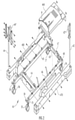
- the patient support apparatus 29 generally comprises a base frame 61, a support deck 50, a segmented patient support surface 11, a lift system 170 (depicted in FIGS. 4 and 5 ) and a stationary exercise support, such as foot plate assembly 41.
- the base frame 61 and the load frame 62 utilized may be similar to the base frame and load frame disclosed in U.S. Patent No. 7,426,760 .
- the base frame 61 may generally comprise longitudinal beams 65 and 66 and transverse elements 63 and 64.
- Base frame 61 further comprises a plurality of casters 34, 35, 36, and 37 conventionally located proximate the four corners of the base frame 61. Locking mechanisms 38 and 39 are provided for at least the front casters 35, 36, respectively.
- the rear casters 34, 37 may be provided with similar locking mechanisms.
- the locking mechanisms may be set to prevent either rotation and/or steering of the casters 35, 36, thereby holding the base frame 61 (and patient support apparatus) stationary with respect to the floor, as is conventional with many hospital bed frames.
- a plurality of accessory weldments, such as accessory weldments 68, 69, 70 and 71 are attached to the base frame 61 on longitudinal beams 65, 66 ( FIG. 2 ).
- the accessory weldments 68, 69, 70, 71 are attached proximate the ends of the longitudinal beams 65, 66.
- the accessory weldments may be attached at various locations along the longitudinal beams 65, 66 or even on the transverse elements 63, 64 of the base frame.
- the accessory weldments 68, 69, 70, 71 receive various attachments, such as stanchions 42,44 on which various accessories may be supported, such as intravenous injection (IV) holders, standard traction frames, and the like.
- stanchions 42, 44 include hand holds 42"-44" which may be used to facilitate patient entrance or exit from the patient support apparatus 29.
- accessory weldments 68, 69, 70, 71 may be used to receive various stationary exercise supports, such a upper extremity exercise assemblies, which may be used in conjunction with the patient support apparatus 29 to perform closed chain exercises to strengthen the upper and/or lower body of a patient, as will be described in more detail herein.
- the base frame 61 may further comprise one or more garnish covers 460, 470, 480 removably positioned over the various operating mechanisms of the patient support apparatus 29.
- the lift system 170 includes load frame 62 which couples the lift system 170 to the base frame 61.
- the load frame 62 supports the various linear actuators (such as jack motors and the like) and related mechanical and electrical components which facilitate raising, lowering and tilting the support deck 50 with respect to the base frame 61 and articulating various portions and/or segments of both the support deck 50 and the segmented patient support surface 11.
- the load frame 62 generally comprises longitudinal beams 72, 73 and transverse elements 74, 75. Additional transverse elements 76, 77 support jack motors 90, 92, within the load frame 62, respectively. The operation of jack motors 90, 92 with respect to the operation of the patient support apparatus 29 will be described further herein.
- linear variable displacement transducers (LVDTs) 88 and 89 are disposed between the load frame 62 and the base frame 61 such that any loads positioned on the load frame (i.e., a patient) is registered by the LVDTs which output a signal indicative of the load to the control unit 174.
- the load frame 62 and base frame 61 are coupled as described in U.S. Pat. No. 4,793,428 , which is herein incorporated by reference.
- the base frame 61 includes a pair of displacement transmitting members 84, 85 which are respectively connected between transverse elements 63 and 74 and 64 and 75 with flexures 78, 79, 80 and 81 and 243, 244, 245 and 246. More specifically, transmitting member 84 is attached to transverse element 63 with flexure 246 and transverse element 74 with flexure 81. Bar elements 82, 83 are connected to members 84 and 85 in a cantilevered manner such that, when a load is applied to the load frame 62, the load is communicated to the bar elements 82, 83 through the transmitting members and flexures. The displacement of the bar elements 82, 83 is limited by springs 86, 87.
- the displacement of the bar elements 82, 83 is measured with the LVDTs 88, 89 which output a signal in direct proportion to the weight of the load frame, and all which is supported thereon, to control unit 174.
- the load frame 62 further comprises a locking mechanism 67 which secures the load frame 62 to the base frame 61 during transport of patient support apparatus 29.
- Tilting of the support deck 50 relative to the base frame 61 may also be referred to herein as orienting the support deck in a Trendelenburg orientation or a reverse Trendelenburg orientation.
- a Trendelenburg orientation a head of the support deck 50 is lower than a foot of the support deck 50 while in a reverse Trendelenburg orientation, the foot of the support deck 50 is lower that the head of the support deck.
- the load frame 62 includes a head torque arm 106 and foot torque arm 110, each of which are pivotally attached to load frame 62.
- a deck frame 150 to which the support deck 50 is pivotally attached, is coupled to the head torque arm 106 and the foot torque arm 110 with linkage members 102, 105, 108, and 109.
- the foot torque arm 110 is pivotally connected to linkage members 108, 109 at locations 101, 107, respectively, using bushings and other conventional hardware.
- the head torque arm 106 is mechanically coupled to jack motor 90 with jack sleeve 91 such that, when the jack motor 90 is actuated, the rotation of the jack motor 90 is translated to the head torque arm 106 through the jack sleeve 91 thereby rotating the head torque arm 106 about pivots 106' and 106".
- the foot torque arm 110 is mechanically coupled to jack motor 92 with jack sleeve 93 such that, when the jack motor 92 is actuated, the rotation of the jack motor 92 is translated to the foot torque arm 110 through the jack sleeve 93 thereby rotating the foot torque arm 110 about pivots 110' and 110".
- the jack motors 90, 92 and corresponding jack sleeves 91, 93 may be linear actuators, such as linear actuators produced by Linak, or any other similar linear actuator.
- the jack motors 90, 92 are attached to the transverse members 76, 77 of load frame 62 with torque arm pins 95, 97 affixed by cotter pins 96 and 98.
- Extension of the jack sleeve 93 by jack motor 92 causes the foot torque arm 110 to pivot relative to load frame 62.
- the rotation of the foot torque arm 110, relative to the load frame 62 articulates the linkage members 108, 109 either upward or downward, depending on the direction of rotation of the jack motor 92.
- extension of the jack sleeve 91 by jack motor 90 causes head torque arm 106 to pivot relative to the load frame 62 and articulates the linkage members 102 and 105 either upward or downward, depending on the rotation of the jack motor 92.
- Articulation of the linkage members 102, 105, 108 and 109 raises, lowers and/or tilts the support deck 50 with respect to the base frame 61.
- the linkage members 102, 105, 108 and 109 are uniformly raised by jack motors 90, 92 (i.e., the "BED UP" function of the control pendant, described further herein), the head and foot of the support deck 50 are uniformly raised.
- the linkage members 102, 105, 108 and 109 are uniformly lowered by jack motors 90, 92 (i.e., the "BED DOWN" function of the control pendant, described further herein)
- the head and foot of the support deck 50 are uniformly lowered.
- the lift system 170 is capable of positioning the support deck at about a ten degrees Trendelenburg orientation and/or about twelve and one half degrees of reverse Trendelenburg orientation.
- the Trendelenburg and reverse Trendelenburg orientations may be achieved utilizing the TRENDELENBURG or REVERSE TRENDELENBURG functions of the control pendants, as will be described in more detail herein.
- the load frame 62 also contains various electronic components of the lift system 170.
- the load frame 62 may also contain the transformer assembly 103 and junction box assembly 104 through which power is supplied to the various jack motors of the lift system 170.
- inductor-capacitor-resistor (LRC) networks 99 and 100 can be mounted on the load frame 62 so as to conserve space within the junction box assembly 104. LRC networks 99 and 100 are used for the capacitive startup of jack motors 90 and 92 and to protect the power distribution system and control system of the patient support apparatus 29 from back electromotive forces (EMF) generated at initial startup of either jack motor 90 or 92.
- EMF back electromotive forces
- the support deck, carriage, and segmented patient support surface described herein can be adapted for use with various other raising, lowering and tilting mechanisms used in commercially available hospital and patient care beds including, without limitation, the Total Care series of beds manufactured by Hill-Rom of Batesville, Indiana and the BariKare series of beds manufactured by Kinetic Concepts Incorporated of San Antonio, Texas.
- the support deck 50 of the patient support apparatus 29 generally comprises at least a seat portion 52.
- the support deck 50 further comprises a leg portion 53 which is pivotally coupled to an end of the seat portion 52 with hinge 20.
- the hinge 20 facilitates pivoting the leg portion 53 of the support deck 50 with respect to the seat portion 52 of the support deck 50 such that the leg portion is positionable between an aligned position wherein the leg portion 53 is substantially coplanar with the seat portion 52 (as shown in FIG. 6 ) and at least one declined position wherein the leg portion 53 is oriented at a downward angle with respect to the seat portion 52 such that the leg portion 53 is non-coplanar with the seat portion 52 (as shown in FIG. 8 ).
- the support deck 50 is pivotally coupled to the deck frame 150 of the lift system 170 such that the support deck 50 can be tilted with respect to the base frame 61, as depicted in FIG. 7 .
- the deck frame 150 of the lift system 170 includes a pair of transverse members 114, 115 coupled to a pair of longitudinal members 112, 113.
- the longitudinal members 112, 113 and transverse members 114, 115 are connected to linkage members 102, 105, 108 and 109 which stabilize deck frame 150.
- the deck frame 150 further comprises bearing pivots 116, 117 positioned at the front (i.e., the foot end) of the deck frame 150.
- the bearing pivots 116, 117 are pivotally coupled to the seat portion 52 of the support deck 50 such that the entire support deck 50 can be tilted to a tilt angle relative to the base frame 61.
- the tilt angle is less than or equal to 90 degrees. In another embodiment, the tilt angle is less than or equal to eighty-five degrees.
- Tilt jack motor 118 is located between weldments to linkage members 102 and 105 and directly positioned on transverse member 114 of the deck frame 150.
- the jack sleeve 119 of the tilt jack motor 118 is pivotally coupled to the underside of the seat portion 52 of the support deck 50 with a connecting yoke 111 located on the end of the jack sleeve 119.
- the tilt jack motor 118 tilts the support deck 50 relative to the base frame 61 by extending and retracting the jack sleeve 119 relative to the load frame 62, as will be described in further detail herein.
- the lift system 170 further comprises a decline jack motor 24.
- the decline jack motor 24 is attached to the underside of the seat portion 52 of the support deck 50.
- Decline jack motor 24 is pivotally attached to the leg portion 53 of the support deck 50 with attachment yolk 26 which is positioned on the end of decline jack sleeve 25. Rotation of the decline jack motor 24 either extends or retracts the decline jack sleeve 25 with respect to the seat portion 52 depending on the direction of rotation of the decline jack motor 24.
- the leg portion 53 of the support deck 50 When the decline jack sleeve 25 is retracted, the leg portion 53 of the support deck 50 is pivoted downwards, to one or more declined positions. However, when the decline jack sleeve 25 is extended, the leg portion of the support deck 50 is pivoted upwards, until the jack sleeve is substantially coplanar with the seat portion 52, as described above. In the embodiments described herein, the leg portion 53 of the support deck 50 is pivotal from the aligned position up to a decline angle of about 90 degrees with respect to the seat portion 52. Pivoting of the leg portion 53 of the support deck 50 with the decline jack motor 24 may be accomplished using a LEGS UP function or a LEGS DOWN function of a control pendant, as will be described in more detail herein.
- the segmented patient support surface 11 generally comprises a torso support segment 30 and an upper leg support segment 31 which are attached to the seat portion 52 of the support deck 50.
- the segmented patient support surface 11 may optionally comprise a lower leg support segment 32 and an ankle support segment 33 attached to the leg portion 53 of the support deck 50.
- the lower leg support segment 32 is removably attached to the lower leg portion, such as with hook and loop closures, straps, snaps, or any other suitable fastener or fastener system.
- the lower leg support segment 32 may include handles 28 (one shown in FIG.
- the segments 30, 31, 32, 33 of the segmented patient support surface 11 generally comprise a synthetic cover material which is filled with a support material, such as foam, synthetic fibers, natural fibers or the like.
- the segments may have a traditional mattress structure which incorporates springs and/or combinations of springs with other support materials.
- the torso support segment 30 and the upper leg support segment 31 of the segmented patient support surface 11 are slidably coupled to the support deck 50 such that the torso support segment 30 and the upper leg support segment 31 are freely slidable with respect to the support deck 50.
- the torso support segment 30 and the upper leg support segment 31 are attached to a carriage 18.
- the carriage 18 is mounted to a pair of spaced longitudinal beams 123, 124 attached to the top surface of the seat portion 52 of the support deck 50 with sliding rails 21, 22 disposed between the spaced longitudinal beams 123, 124 and the carriage 18 such that the carriage 18 (and therefore torso support segment 30 and the upper leg support segment 31) is slidable with respect to the support deck 50 (i.e., the sliding rails 21, 22 slidably couple the carriage 18 to the spaced longitudinal beams 123, 124).
- the carriage 18, torso support segment 30 and upper leg support segment 31 are generally slidable between a head of the support deck 50 and a foot of the support deck 50.
- the support deck 50 comprises a seat portion 52 and a leg portion 53 which is pivotable with respect to the seat portion 52 about a hinge 20.
- the location of the hinge 20 prevents the use of conventional, fixed sliding rails which would be affixed to both the seat portion 52 and the leg portion 53 thereby extending over the hinge 20 and preventing the leg portion 53 from pivoting with respect to the seat portion 52.
- the sliding rails 21, 22 are telescoping sliding rails which are fixedly attached to the spaced longitudinal beams 123, 124 on the seat portion 52 of the support deck 50.
- the sliding rails 21, 22 have an extended position where the sliding rails 21, 22 are positioned over at least a portion of the support deck 50 (as shown in dashed lines in FIG. 14A ) and a retracted position, where the sliding rails 21, 22 are not positioned over the leg portion 53 of the support deck 50.
- the sliding rails may be model no. SR28-770 or SR 43-770 ball semi-telescopic rail slides manufactured by Linear Trace SRL (Cinisello, Italy). However, it should be understood that other, similar telescoping sliding rails may be used.
- the torso support segment 30 of the segmented patient support surface 11 is pivotable with respect to the upper leg support surface 31 such that the torso support segment 30 is positionable with respect to the upper leg support segment 31 from a recumbent position, wherein the torso support segment and the upper leg support segment are substantially coplanar (as depicted in FIG. 13 ), and at least one inclined position, wherein the torso support segment is non-coplanar with the upper leg support segment (as depicted in FIG. 6 ).
- the patient support apparatus 29 may include an incline jack motor 55.
- the torso support segment 30 is fixedly attached to a head frame 51.
- the incline jack motor 55 is pivotally coupled to the underside of the head frame 51 with coupling yolk 57.
- the incline jack sleeve 56 of the incline jack motor 55 is pivotally coupled to a cross support 130 of the carriage 18. Accordingly, extending the incline jack sleeve 56 with the incline jack motor 55 pivots the torso support segment 30 to at least one inclined position with respect to the upper leg support segment 31 while retracting the incline jack sleeve 56 with the incline jack motor 55 pivots the torso support segment 30 to the recumbent position with respect to the upper leg support segment 31.
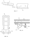
- the patient support apparatus 29 may further comprise an adjustable brake assembly 49 mounted on the support deck 50 and engaged with the carriage 18.
- the adjustable brake assembly 49 assists in preventing the rapid acceleration of the carriage 18 with respect to the support deck 50, particularly when the support deck 50 is inclined with respect to the base frame 61. Accordingly, it should be understood that the adjustable brake assembly is capable of regulating the rate of travel of the segmented patient support surface relative to the support deck.
- the adjustable brake assembly 49 comprises a centrifugal brake 48 which is mounted on a threaded post 204 attached to the seat portion 52 of the support deck 50.
- the centrifugal brake is a Flo-Guide TM speed controller (commonly referred to as a "pallet brake"), model E40, manufactured and sold by Mallard Manufacturing Corporation of Sterling, Illinois.
- the centrifugal brake 48 is engaged with a wear element 131 attached to the carriage 18 such that, as the carriage 18 slides on the sliding rails 21, 22, the centrifugal brake 48 rolls over the wear element 131.
- the centrifugal brake rolls freely under the carriage.
- the centrifugal brake 48 resists the increase in speed and slows the carriage to a controlled speed.
- the position of the centrifugal brake 48 is adjustable on the threaded post 204 by rotating knob 5 and thereby increasing or decreasing the frictional force between the centrifugal brake 48 and the wear element 131 and, as such, the stopping force of the centrifugal brake 48.
- adjustable brake assembly 49 has been described herein as comprising a centrifugal brake 48, other forms of adjustable braking mechanisms are contemplated.
- the adjustable braking mechanism may include an electro-magnetic braking device, an eddy current braking device, or any other suitable adjustable braking device.
- the carriage 18 can be releasably secured to the seat portion 52 of the support deck 50 with carriage lock mechanism 19.
- the carriage lock mechanism 19 comprises a retractable lock pin 220 that can be inserted into one of a plurality of apertures 14 formed in the seat portion 52 of the support deck 50. Lifting the retractable lock pin 220 and turning the pin counter-clockwise disengages the locking pin from the support deck 50, allowing free movement of the carriage. Turning the pin clockwise positions the pin 229 in an aperture 14 and secures the carriage to the support deck 50.
- a lock pin sensor 172 is positioned on an underside of the seat portion 52 and detects when the retractable lock pin 220 is positioned in the one of the plurality of apertures 14.
- the lock sensor 172 may be a pressure sensor, a proximity sensor or any other sensor suitable for detecting the presence of the retractable lock pin 220 in an aperture.
- the support deck 50 may also comprise a range of motion stop assembly 180.
- the range of motion stop assembly 180 includes a plurality of stop pins 182 positioned in apertures 8 formed in the seat portion 52 of the support deck 50.
- the apertures 8 and stop pins 182 are positioned in a path of travel of the carriage 18 such that, when a stop pin 182 is in a raised position, the stop pin 182 engages with the carriage thereby preventing the carriage 18 from further motion with respect to the support deck.
- the stop pins 182 comprise a head 184, a shaft 186, a retaining ball 188 disposed in the shaft, and a retaining disc 210 surrounding the shaft 186.
- the stop pins 182 are positioned in the apertures 8 such that, when the stop pins are fully inserted into seat portion 52, the heads 184 of the stop pins 182 are flush with the top surface of the seat portion 52.
- the seat portion 52 of the support deck 50 may also include an intermediate substrate 208 located on an underside of the seat portion 52. The intermediate substrate 208 engages with the retaining ball 188 when the stop pins 182 are in a raised position, thereby maintaining the stop pins 182 in a raised position with respect to the seat portion 52.
- the retaining discs 210 prevent the stop pins from being completely withdrawn from the apertures 8.
- the range of motion stop assembly 180 further comprises a stop pin sensor 168 positioned beneath the seat portion 52 of the support deck 50.
- the stop pin sensor 168 detects when one or more of the retractable lock pins 220 is in a raised position with respect to the support deck 50.
- the stop pin sensor 168 may comprise a plurality of pressure sensors, a plurality of proximity sensors, a plurality of continuity sensors, or any other sensor suitable for detecting the state (i.e., raised or lowered) of the stop pins with respect to the support deck 50.
- the lower leg support segment 32 is removably positioned on the leg portion 53 of the support deck 50, as described hereinabove.
- the leg portion 53 may include a cushion sensor 166 positioned on the top surface of the leg portion 53.
- the cushion sensor 166 may comprise a proximity sensor, a pressure sensor, a light sensor or any other sensor suitable for detecting the presence of the lower leg support segment 32 on the leg portion 53 of the support deck 50.
- the patient support apparatus 29 further comprises a stationary exercise support, such as foot plate assembly 41, removably positioned on the support deck 50.
- a stationary exercise support such as foot plate assembly 41
- the foot plate assembly 41 is positioned proximate a free end of the support deck 50.
- the foot plate assembly 41 is positioned proximate a free end of the leg portion 53 of the support deck 50.
- the foot plate assembly 41 is positioned to receive the feet of a patient when the patient is positioned on the segmented patient support surface 11 thereby enabling the patient to slide the segmented patient support surface 11 relative to the support deck 50 to perform a closed chain exercise.
- the foot plate assembly 41 comprises a right foot plate 46 and a left foot plate 47.
- the right footplate 46 is removably positioned in the mounting holes 125 and 126 formed in the leg portion 53 of the support deck 50.
- the left foot plate 47 is attached to the support deck 50 in a similar manner.
- the left foot plate 47 and the right foot plate 46 may be removed from the support deck 50 and stored in foot plate storage weldments 225, 226 located on the base frame 61 (right foot plate depicted in storage weldments 225, 226 in FIG. 9 ).
- the foot plate assembly 41 comprises at least one load sensor, such as an LVDT, a piezo-electric pressure transducer or the like, for determining a weight applied to the foot plate assembly 41 by a patient.
- the left foot plate 47 comprises a left foot load sensor 162 (shown in FIG. 12 ) and the right foot plate 46 comprises a right foot load sensor 164.
- the left foot and right foot load sensors 164, 162 are communicatively coupled to the control unit 174.
- stationary exercise support assembly has been described herein as comprising a foot plate assembly, is should be understood that other stationary exercise support assemblies may be used.
- the stationary exercise support assembly may be a pull-up bar assembly, as described further herein.
- the patient support apparatus 29 further comprises a pair of side rails 40 positioned on each side of the support deck 50.
- the side rails 40 are attached to the underside of the support deck 50 and have a raised position relative to the support deck 50, as shown in FIG. 1 , and a lowered position relative to the support deck 50.
- side rail 40 further comprises a weight display 201.
- the weight display 201 is communicatively coupled to the control unit 174 and is operable to display the weight supported by the support deck 50 as registered by the LVDTs located in the load frame 62 and/or the weight applied to the right foot plate 46 and the left foot plate 47 as registered by the right foot plate load sensor and the left foot plate load sensor, respectively.
- Side rail 40 can be oriented in the lowered position by pulling the side rail release bar 133 thereby permitting access to the segmented patient support surface 11 by the patient and/or a care giver.
- the side rails 40 may further comprise one or more exercise handles 140 slidably coupled to the side rails.
- the exercise handle 140 can be adjusted along the length of the side rail by loosening knob 142 that secures the handle to the rail. When not in use, the exercise handle 140 can be rotated on the side rail to prevent interference with the patient's movement on the segmented patient support surface.
- the control system 200 generally comprises a control unit 174 having a memory 176 for storing computer readable and executable instructions and a processor 178 communicatively coupled to the memory 176.
- the processor 178 is operable to read the computer readable and executable instructions stored in the memory 176.
- the control system 200 also comprises a user interface 160 which, in the embodiments described herein, includes a patient control pendant 45 and a therapy control pendant 94 (shown in FIG. 21 ).
- the patient control pendant and the therapy control pendant enable a user to control the orientation of various components of the patient support apparatus with various input devices (such as buttons, knobs and the like).
- the control unit 174 receives signals from the user interface 160 and adjusts the position of the support deck and/or the segmented patient support surface based on the signals received by sending control signals to the jack motors 24, 55, 90, 92, 118 of the lift system 170. Accordingly, it should be understood that the jack motors 24, 55, 90, 92, 118 are communicatively coupled to the control unit 174 and, more specifically, the processor 178 such that the processor 178 can operate the jack motors to achieve the desired patient support apparatus configuration based on user inputs to the control pendants 45, 94.
- the pendants 45, 94 of the user interface 160 enable a user to control the configuration of the patient support apparatus.
- the patient control pendant 45 includes HEAD UP and HEAD DOWN functions which enable a user to adjust the torso support segment with respect to the upper leg support segment to a recumbent position wherein the torso support segment and the upper leg support segment are substantially coplanar or to at least one inclined position wherein the torso support segment is non-coplanar with the upper leg support segment.
- the patient control pendant 45 also includes BED UP and BED DOWN functions which enable the user to raise and lower the support deck and the segmented patient support surface with respect to the base frame.
- the patient control pendant 45 may also include FOOT UP and FOOT DOWN functions which enable a user to adjust the leg portion of the support deck to the aligned position wherein the leg portion is substantially coplanar with the seat portion of the support deck or to at least one declined position where in the leg portion is non-coplanar with the seat portion of the support deck.
- the patient control pendant 45 may also include TREND UP and TREND DOWN functions which enable the user to orient the support deck and segmented patient support surface to the TRENDELENBURG orientation or REVERSE TRENDELENBURG orientation, as described herein. In the embodiment shown in FIG.
- the patient control pendant 45 also includes a CHAIR function which positions the upper torso support segment to a fully inclined position with respect to the support deck and upper leg support segment and positions the leg portion of the support deck to a fully declined position with respect to the seat portion of the support deck.
- the therapy support pendant 94 includes TILT UP and TILT DOWN functions which allow a user, specifically a care giver, to increase or decrease the tilt the support deck relative to the base frame.
- the left and right foot plate load sensors 162, 164 are communicatively coupled to the control unit 174 and operable to send signals to the control unit indicative of the weight applied to each foot plate.
- the LVDTs 88, 89 of the load frame are communicatively coupled to the control unit 174 and operable to send signals to the control unit 174 indicative of the weight applied to the load frame.
- the weight display 201 is communicatively coupled to the control unit 174.
- the processor 178 receives the signals from the left and right foot plate load sensors 162, 164 and the LVDTs 88, 89 and displays the weight registered by these sensors on the weight display 201.
- the cushion sensor 166 positioned on the leg portion of the support deck and the stop pin sensor 168 of the range of motion stop assembly are also communicatively coupled to the control unit 174.
- the lock sensor 172 is also communicatively coupled to the control unit 174.
- the control system 200 may also comprise an exercise mode indicator 260 which includes a cushion indicator 262, a stop pin indicator 264, a tilt OK indicator 266 and, in some embodiments, a carriage lock indicator 268, each of which are communicatively coupled to the control unit 174.
- the exercise mode indicator 260 may be positioned on a side rail of the patient support apparatus or, alternatively, on the therapy control pendant 94 or the patient control pendant 45 of the user interface.
- Indicators 262, 264, 266, 268 may be visual indicators, such as LEDs or the like, and/or audible indicators, such as a buzzer or an electronic chime.
- the control unit 174 is operable to receive signals from the cushion sensor 166, the stop pin sensor 168 and the lock sensor 172 and illuminate the corresponding indicator upon the occurrence of a specified condition.
- the cushion indicator 262 is activated by the control unit 174 when the signal received from the cushion sensor 166 indicates that the lower leg support segment is not positioned on the leg portion of the support deck.
- the stop pin indicator 264 is activated by the control unit 174 when the signal received from the stop pin sensor 168 indicates that one or more of the stop pins is in a raised position in the path of travel of the carriage.
- the carriage lock indicator 268 is activated by the control unit 174 when the lock sensor 172 indicates that the carriage lock pin is inserted in the support deck.
- control unit 174 is programmed to prevent the support deck from being tilted into an exercise orientation until the cushion sensor 166, the stop pin sensor 168, and the lock sensor 172 respectively indicate that the lower leg support segment has been removed from the leg portion of the support deck, at least one stop pin is raised from the support deck and positioned in the path of travel of the carriage, and the carriage lock is not inserted in the support deck.
- the control unit 174 activates the tilt OK indicator 266 and permits the support deck to be tilted by a user through the user interface 160.
- the control unit 174 is programmed to prevent the support deck from being tilted into an exercise orientation until the cushion sensor 166 and the stop pin sensor 168 indicate that the lower leg support segment has been removed from the leg portion of the support deck and at least one stop pin is raised from the support deck and positioned in the path of travel of the carriage.
- the control unit 174 activates the tilt OK indicator 266 and permits the support deck to be tilted by a user through the user interface 160.
- FIG. 6 the patient support apparatus is depicted in a bed orientation.
- FIG. 6 depicts the patient support apparatus 29 in the conventional bed orientation with the support deck 50 in a neutral orientation (i.e. a substantially horizontal orientation) and the side rail 40 in the raised position.
- the torso support segment 30 of the segmented patient support surface is elevated by the incline jack motor 55 and incline jack sleeve 56 such that the torso of the patient is slightly inclined with respect to the patient's legs.
- This orientation may be achieved by actuating the incline jack motor 55 with the HEAD UP function of the patient control pendant.
- the torso support segment 30 may also be lowered to a horizontal position utilizing the HEAD DOWN function of the patient control pendant to actuate the incline jack motor 55.
- the patient support apparatus is depicted in a reclining chair orientation.
- the leg portion 53 of the support deck 50 is in a decline position which is achieved by actuating the decline jack motor 24 with the LEGS DOWN function of the patient control pendant.
- the torso support segment 30 is in an inclined position such that the torso support segment 30 is non-coplanar with the upper leg support segment 31 which may be achieved by actuating the incline jack motor 55 with the HEAD UP function of the patient control pendant.
- the support deck 50, and more specifically, the seat portion 52 of the support deck 50 may be tilted with respect to the base frame such that the head end of the seat portion is declined.
- the lower leg support segment is not positioned on the leg portion 53 of the support deck 50.
- the reclining chair orientation of the patient support apparatus may be achieved with the CHAIR function of the patient control pendant 45.
- the patient support apparatus is positioned in the egress orientation.
- the egress orientation is achieved by actuating the decline jack motor 24 with the LEGS DOWN function of the patient control pendant to bring leg portion 53 of the support deck 50 to a maximum decline position while the torso support segment 30 is pivoted to an inclined position such that the torso support segment 30 is non-coplanar with the upper leg support segment 31 by actuating the incline jack motor 55 with the HEAD UP function of the patient control pendant.
- the left and right foot plates are removed from the leg portion 53 of the support deck and stowed in the foot plate storage weldments 225, 226.
- the right foot plate 46 is depicted stowed in the foot plate storage weldments 225, 226 in FIG. 9 . Removal of the foot plates allows the feet of the patient to contact the ground and thereby transition to standing. To facilitate the egress orientation the seat portion 52 of the support deck is lowered to its lowest position relative to the base frame 61 by using the patient pendant control to actuation of the jack motors. In the embodiment shown in FIG. 9 a stanchion 44 with handle 44" is positioned at the end of the base frame 61 to assist the patient in transitioning to a standing position.
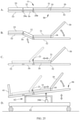
- the patient support apparatus 29 is shown in an exercise orientation.
- the foot plate assembly 41 is positioned on the leg portion 53 of the support deck 50 and the leg portion 53 is in the aligned position with respect to the seat portion 52 of the support deck 50.
- the support deck 50 is raised relative to the base frame 61 which may be accomplished by using the BED UP function of the patient control pendant to actuate the jack motors in the load frame.
- the torso support segment 30 is in an inclined position such that the torso support segment 30 is non-coplanar with the upper leg support segment 31 which may be achieved by actuating the incline jack motor 55 with the HEAD UP function of the patient control pendant.
- the support deck is tilted with respect to the base frame such that the seat portion of the support deck is higher than the leg portion of the support deck. This positioning may be accomplished by actuating the tilt jack motor 118 with the TILT UP function of the therapy control pendant. As described hereinabove with respect to the control system depicted in FIG. 24 , the TILT UP function of the therapy control unit may be locked out and tilting of the support deck may be prevented by the control until at least the lower leg support segment is removed from the leg portion 53 of the support deck 50 and at least one stop pin 182 is positioned in the path of travel of the carriage 18 on the support deck 50, as is depicted in FIG. 10 . Once the carriage lock mechanism 19 has been disengaged, the carriage 18 and the upper leg support segment 31 and torso support segment 30 are freely slidable on the patient support deck 50.
- a patient is depicted seated in the patient support apparatus 29 with the patient support apparatus in the exercise orientation. Specifically, the patient is seated on the upper leg support segment 31 such that the patients feet are engaged with the foot plate assembly 41 and the patient is reclined against the torso support segment 30. The patient is secured to the torso support segment 30 with support strap 16 which is secured to strap weldments 12, 13 located at either side of the underside of the torso support segment 30. The patient is depicted performing a closed chain exercise which, in the embodiment shown in FIG. 10 , is a leg press exercise.
- the leg press exercise is accomplished by the patient pressing against the foot plate assembly 41 as the patient straightens his or her legs which, in turn, slides the carriage 18 upwards on the support deck 50 and away from the foot plate assembly 41. The patient then bends his or her knees to slide the carriage 18 back towards the foot plate assembly 41 in a controlled manner.
- the brake assembly (not shown) described hereinabove, prevents the rapid acceleration of the carriage 18 with respect to the support deck 50.
- the stop pins 182 limit the range of motion of the carriage 18 in the direction towards the foot plate assembly 41. Resistance during the leg press exercise is a fraction of the patient's body weight and is dependent on the tilt angle of the support deck 50 with respect to the base frame 61.
- a tilt angle of 20-degrees is approximately 45% body weight and a tilt angle of 35-degrees is approximately 75% body weight.
- the patient can perform a leg press exercise with a tolerable amount of resistance to enhance leg strength in preparation for standing.
- an angle indicator 9 is located at the bearing pivot 116 and provides a visual indication of the tilt angle of the support deck 50 with respect to the base frame 61.
- Therapy control pendant 94 may be used to control the tilt jack motor 118 with the TILT UP or TILT DOWN functions, as described above.
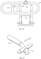
- the patient support apparatus 29 is depicted being used to perform a closed chain exercise which, in this embodiment, is an upper extremity exercise performed with a second type of stationary exercise support, specifically an upper extremity exercise assembly.
- a closed chain exercise which, in this embodiment, is an upper extremity exercise performed with a second type of stationary exercise support, specifically an upper extremity exercise assembly.
- at least one stanchion 44 is attached to the base frame 61 and an upper extremity exercise assembly is attached to the stanchion.
- the upper extremity exercise assembly includes at least one cable 59 connected to the carriage 18 at eye bolt 120.
- the cable 59 is routed through at least one pulley 58 which is connected to the stanchion 44.
- a free end of the cable 59 may include a handle 60 which a patient may grasp.
- the patient support apparatus 29 is depicted being used to perform a closed chain exercise with yet another type of stationary exercise support which, in this embodiment, is an upper extremity exercise, specifically a pull-up bar assembly.
- an upper extremity exercise specifically a pull-up bar assembly.
- at least one stanchion 44 is attached to the base frame 61 and an upper extremity exercise assembly is attached to the stanchion.
- the upper extremity exercise assembly includes a pull-up bar assembly 190 attached to the stanchion 44.
- the pull-up bar assembly includes a support strut 194 which is coupled to the stanchion 44 with an adjustable fitting 196 such that the pull-up bar is vertically adjustable (i.e., in the + or - Z direction of the coordinate axes shown in FIG.
- a pull-up bar 192 is attached at the opposite end of the support strut 194 with pull-up bar mount 198 such that the pull-up bar is positioned over the patient.
- the patient may grasp and pull against the pull-up bar assembly thereby sliding the segmented patient support surface with respect to the support deck.
- the patient support apparatus is depicted in use by an amputee patient to perform a unilateral leg strengthening exercise.
- the patient support apparatus is oriented in the exercise orientation as described hereinabove with respect to FIG. 10 .
- an amputee support pad 4 is attached to the carriage 18.
- the amputee support pad 4 is secured into a support pad receptacle 6 located on the free end of the carriage 18 (see FIG. 17 ).
- the amputee support pad has a restraining strap 3 which secures the injured limb and elevates the limb to allow one leg squat exercise to be performed on the patient support apparatus.
- the footplate on the side of the amputee support pad 4 is removed to allow the patient to exercise without the injured limb contacting the footplate.
- This function can be used for patients with either an amputation or a non-weight-bearing limb, such as a fractured leg or hip, to allow strengthening of the unaffected leg.
- the patient support apparatus 29 is depicted in a tilt orientation wherein the support deck is tilted up to angle of less than 90 degrees with respect to the base frame 61.
- the tilt angle of the support deck 50 is 85 degrees or less.
- the carriage is locked to the support deck 50 with the carriage lock mechanism 19 thereby preventing movement of the carriage with respect to the support deck 50.
- the leg portion 53 of the support deck 50 is in the aligned position with respect to the seat portion 52 of the support deck 50 which is achieved with the LEGS UP function of the patient control pendant.
- the torso support segment 30 is in the recumbent position with respect to the upper leg support segment 31 which is achieved with the HEAD DOWN function of the patient control pendant.
- the support deck 50 is tilted with respect to the base frame 61 by actuating the tilt jack motor 118 with the TILT UP function of the therapy control pendant.
- the patient is secured to patient support apparatus at the chest, waist and knees with support straps 15, 16 and 17.
- the straps are secured to strap weldments 12, 121, 122 located on the underside of the patient support surface.
- the patient support apparatus has been described herein as comprising a support deck to which the torso support segment and the upper leg support segment of a segmented patient surface are slidably coupled. Moreover, the patient support deck has been described as comprising a seat portion and a leg portion which facilitates positioning the patient support apparatus in a chair orientation. However, it should be understood that embodiments of the patient support apparatus which facilitate a leg elevation orientation are also contemplated.
- the support deck 50 includes a seat portion 52, an intermediate portion 54 pivotally coupled to an end of the seat portion 52 with hinge 20b, and a leg portion 53 pivotally coupled to an end of the intermediate portion 54 with hinge 20a.
- a conventional lift system (not shown) may be coupled to the support deck 50 to enable pivoting the intermediate portion 54 with respect to the seat portion 52 and the leg portion 53 with respect to the intermediate portion 54 such that the leg portion 53 is elevated relative to the seat portion 52 to achieve a leg elevation orientation, as depicted in FIG. 25B .
- the intermediate portion 54 of the support deck 50 is positionable in an aligned position wherein the intermediate portion 54, the leg portion 53 and the seat portion 52 are substantially coplanar with one another, as depicted in FIG. 25A .
- the intermediate portion 54 is also positionable in at least one intermediate position wherein the intermediate portion 54 is inclined with respect to the seat portion 52 and declined with respect to the leg portion 53, as shown in FIG. 25B .
- a segmented patient support surface 11 is positioned on the support deck 50 and comprises a torso support segment 30, an upper leg support segment 31, and a lower leg support segment 32, and an ankle support segment 33 as described hereinabove.
- both the lower leg support segment 32 and the ankle support segment 33 are removably attached to respective portions of the support deck 50 so as to enable an exercise orientation of the support deck 50 and upper leg support segment 31.
- a foot plate assembly 41 may be removably attached to the leg portion 53 of the support deck 50 as described hereinabove.
- the torso support segment 30 and the upper leg support segment 31 are slidably coupled to the support deck 50 such that the torso support segment 30 and the upper leg support segment 31 are freely slidable with respect to the support deck 50, as described hereinabove and shown in FIGS. 25C and 25D .
- the torso support segment 30 and the upper leg support segment 31 are slidably attached to the seat portion 52 with carriage 18.
- the carriage 18 is coupled to the seat portion 52 with sliding rails 21, such as telescopically sliding rails, which enable the carriage to slide relative to the support deck 50, as described hereinabove.
- the lift system may also be coupled to the torso support segment 30 such that the torso support segment is pivotable with respect to the upper leg support segment from a reclined position wherein the torso support segment and the upper leg support segment are substantially coplanar, as shown in FIG. 25A , and at least one inclined position wherein the torso support segment is non-coplanar with the upper leg support segment as shown in FIG. 25B .
- Patient support apparatuses with support decks of this configuration may have an exercise orientation as depicted in FIG. 25D .
- the lower leg support segment 32 and the ankle support segment 33 are removed from the support deck 50 and the torso support segment 30 is in the inclined position with respect to the upper leg support segment 31 and the intermediate portion 54 of the support deck 50 is positioned in an aligned position such that the intermediate portion 54 is substantially coplanar with the seat portion 52 and the leg portion 53.
- the support deck 50 is tilted with respect to the base frame 61 such that the seat portion 52 of the support deck 50 is higher that the leg portion 53 of the support deck 50 relative to the base frame 61.
- Tilting the support deck in this manner may be accomplished with jack motor 290 positioned in load frame 62, to which the support deck 50 is pivotally attached.
- the carriage, torso support segment 30, and upper leg support segment 31 are freely slidable on the support deck 50 towards and away from foot plate assembly 41.
- the patient support apparatus may then be used to perform closed chain exercises, as described hereinabove.
- the patient support apparatuses described herein can be configured in a bed orientation, a chair orientation, an egress orientation, an exercise orientation, or a tilt orientation.
- the patient support apparatus may also be utilized as a tilt table to assist with raising a patient to a standing position.
- having the torso support segment and the upper leg support segment slidably coupled to the support deck facilitates use of the patient support apparatus to perform closed chain exercises which utilize a patient's own body weight to increase the strength and range of motion of both upper and lower extremities, and to improve the conditioning of a patient.
- the braking assembly incorporated in the patient support apparatus may be used to mitigate rapid acceleration of the torso support segment and the upper leg support segment relative to the support deck thereby providing more uniform resistance throughout the complete range of motion of the exercise.
Landscapes
- Health & Medical Sciences (AREA)
- General Health & Medical Sciences (AREA)
- Life Sciences & Earth Sciences (AREA)
- Public Health (AREA)
- Animal Behavior & Ethology (AREA)
- Veterinary Medicine (AREA)
- Nursing (AREA)
- Orthopedic Medicine & Surgery (AREA)
- Physical Education & Sports Medicine (AREA)
- Rehabilitation Therapy (AREA)
- Biophysics (AREA)
- Epidemiology (AREA)
- Pain & Pain Management (AREA)
- Invalid Beds And Related Equipment (AREA)
- Accommodation For Nursing Or Treatment Tables (AREA)
Claims (4)
- Appareil de support de patient (29) doté de fonctionnalités d'exercice à chaîne fermée, le support de patient comprenant :un châssis de base (61) ;une plateforme de support (50) supportée sur le châssis de base (61), la plateforme de support (50) comprenant une partie siège (52) ;une surface de support de patient segmentée (11) comprenant un segment de support de cuisse (31) couplé tout en pouvant coulisser par rapport à la plateforme de support (50), de sorte que le segment de support de cuisse (31) puisse coulisser librement par rapport à la plateforme de support (50) ;un système de levage (170) couplé à la plateforme de support (50) et à la surface de support de patient segmentée (11), le système de levage (170) permettant de soulever, abaisser et incliner la plateforme de support (50) par rapport au châssis de base (61) ; etun ensemble plaque de pied (41) placé de façon amovible près d'une extrémité libre de la partie jambe de la plateforme de support (50), l'ensemble plaque de pied (41) recevant les pieds d'un patient lorsqu'un patient est placé sur la surface de support de patient segmentée (11), permettant ainsi au patient de faire glisser la surface de support de patient segmentée (11) par rapport à la plateforme de support (50) pour effectuer un exercice à chaîne fermée, caractérisé en ce que la plateforme de support (50) comprend en outre une partie jambe (53) couplée et pouvant pivoter par rapport à la partie siège (52), le système de levage (170) permettant de faire pivoter la partie jambe (53) par rapport à la partie siège (52).
- Appareil de support de patient (29) de la revendication 1, dans laquelle l'appareil de support de patient (29) présente une orientation d'exercice dans laquelle :la partie jambe (53) de la plateforme de support (50) est dans une position alignée par rapport à la partie siège (52) de la plateforme de support (50) ; etla plateforme de support (50) est inclinée par rapport au châssis de base (61) de sorte que la partie siège (52) de la plateforme de support (50) est plus haute que la partie jambe (53) de la plateforme de support (50).
- Appareil de support de patient (29) de la revendication 1, dans laquelle l'appareil de support de patient (29) présente une orientation de sortie dans laquelle :la partie jambe (53) de la plateforme de support (50) est placée dans au moins l'une des positions baissées par rapport à la partie siège (52) de la plateforme de support (50) ; etla plateforme de support (50) est à sa position basse par rapport au châssis de base (61).
- Appareil de support de patient (29) de la revendication 1, dans laquelle l'appareil de support de patient (29) présente une orientation inclinée dans laquelle :la partie jambe (53) de la plateforme de support (50) est dans une position alignée par rapport à la partie siège (52) de la plateforme de support (50) ; etla plateforme de support (50) est inclinée par rapport au châssis de base (61), un angle d'inclinaison entre la plateforme de support (50) et le châssis de base (61) étant supérieur à zéro et inférieur ou égal à environ 90 degrés.
Applications Claiming Priority (4)
| Application Number | Priority Date | Filing Date | Title |
|---|---|---|---|
| US28417809P | 2009-12-14 | 2009-12-14 | |
| PCT/US2010/058786 WO2011081774A2 (fr) | 2009-12-14 | 2010-12-02 | Appareils de support de patient munis de fonctionnalités d'exercice |
| EP10841451.7A EP2512393B1 (fr) | 2009-12-14 | 2010-12-02 | Appareils de support de patient munis de fonctionnalités d'exercice |
| EP17179619.6A EP3254658B1 (fr) | 2009-12-14 | 2010-12-02 | Appareils de support de patient ayant des éléments d'exercice |
Related Parent Applications (3)
| Application Number | Title | Priority Date | Filing Date |
|---|---|---|---|
| EP17179619.6A Division EP3254658B1 (fr) | 2009-12-14 | 2010-12-02 | Appareils de support de patient ayant des éléments d'exercice |
| EP17179619.6A Division-Into EP3254658B1 (fr) | 2009-12-14 | 2010-12-02 | Appareils de support de patient ayant des éléments d'exercice |
| EP10841451.7A Division EP2512393B1 (fr) | 2009-12-14 | 2010-12-02 | Appareils de support de patient munis de fonctionnalités d'exercice |
Publications (2)
| Publication Number | Publication Date |
|---|---|
| EP3653187A1 EP3653187A1 (fr) | 2020-05-20 |
| EP3653187B1 true EP3653187B1 (fr) | 2022-01-26 |
Family
ID=44143597
Family Applications (3)
| Application Number | Title | Priority Date | Filing Date |
|---|---|---|---|
| EP17179619.6A Active EP3254658B1 (fr) | 2009-12-14 | 2010-12-02 | Appareils de support de patient ayant des éléments d'exercice |
| EP10841451.7A Active EP2512393B1 (fr) | 2009-12-14 | 2010-12-02 | Appareils de support de patient munis de fonctionnalités d'exercice |
| EP19217688.1A Active EP3653187B1 (fr) | 2009-12-14 | 2010-12-02 | Appareils de support de patient ayant des éléments d'exercice |
Family Applications Before (2)
| Application Number | Title | Priority Date | Filing Date |
|---|---|---|---|
| EP17179619.6A Active EP3254658B1 (fr) | 2009-12-14 | 2010-12-02 | Appareils de support de patient ayant des éléments d'exercice |
| EP10841451.7A Active EP2512393B1 (fr) | 2009-12-14 | 2010-12-02 | Appareils de support de patient munis de fonctionnalités d'exercice |
Country Status (3)
| Country | Link |
|---|---|
| US (2) | US8858409B2 (fr) |
| EP (3) | EP3254658B1 (fr) |
| WO (1) | WO2011081774A2 (fr) |
Families Citing this family (145)
| Publication number | Priority date | Publication date | Assignee | Title |
|---|---|---|---|---|
| US8864205B2 (en) | 2006-06-28 | 2014-10-21 | Stryker Corporation | Patient support with wireless data and/or energy transfer |
| US8856988B2 (en) * | 2010-10-12 | 2014-10-14 | Michael O. Frazier | Adjustable support for a residual limb of an amputee |
| US8522379B2 (en) * | 2010-11-15 | 2013-09-03 | Hill-Rom Services, Inc. | Hospital bed foot section with caster cutouts |
| CA2854259C (fr) * | 2011-02-15 | 2019-01-15 | Wisys Technology Foundation, Inc. | Systemes de vibration musculosquelettique pour membres articules |
| US20120246830A1 (en) * | 2011-03-31 | 2012-10-04 | Hornbach David W | Footboard egress design |
| US9072931B2 (en) | 2013-10-23 | 2015-07-07 | Spx Fitness, Inc. | Exercise machine carriage system |
| FR2985904B1 (fr) * | 2012-01-20 | 2014-12-19 | Medicatlantic Sa | Lit comprenant une barriere escamotable munie d'un point d'aide technique au roulement |
| EP2712597A2 (fr) * | 2012-09-27 | 2014-04-02 | Multifit Hospital Supplies Limited | Améliorations apportées à des chaises de lit |
| US9283422B2 (en) | 2012-10-29 | 2016-03-15 | Spx Fitness, Inc. | Pilates machine tension device support system |
| US9981156B2 (en) | 2015-10-21 | 2018-05-29 | Lagree Technologies, Inc. | Exercise machine with multiple contact surfaces |
| EP2919866B8 (fr) * | 2012-11-16 | 2020-03-04 | Hill-Rom Services, Inc. | Appareils de soutien des personnes dotés d'éléments de rééducation par l'exercice |
| EP2969058B1 (fr) | 2013-03-14 | 2020-05-13 | Icon Health & Fitness, Inc. | Appareil d'entraînement musculaire ayant un volant, et procédés associés |
| US9630042B2 (en) * | 2013-04-01 | 2017-04-25 | Jason J. Kucharski | Method and apparatus for extremity rehabilitation |
| US9625884B1 (en) * | 2013-06-10 | 2017-04-18 | Timothy Harris Ousley | Apparatus for extending control and methods thereof |
| US10940359B2 (en) | 2013-08-26 | 2021-03-09 | Lagree Technologies, Inc. | Exercise machine inclination device |
| US9370679B2 (en) * | 2013-08-26 | 2016-06-21 | Spx Fitness, Inc. | Multi-axis adjustable exercise machine |
| US9517375B2 (en) * | 2013-08-26 | 2016-12-13 | Lagree Technologies, Inc. | Exercise machine support system |
| US10279207B2 (en) | 2013-08-26 | 2019-05-07 | Lagree Technologies, Inc. | Exercise machine support system |
| US9545535B2 (en) | 2013-08-26 | 2017-01-17 | Lagree Technologies, Inc. | Exercise machine inclination device |
| US9138606B2 (en) | 2013-10-25 | 2015-09-22 | Spx Fitness, Inc. | Exercise machine ergonomic handle system |
| DE202013105360U1 (de) * | 2013-11-25 | 2015-02-26 | Dewertokin Gmbh | Beleuchtungseinrichtung zur Verwendung mit einem elektromotorischen Möbelantrieb |
| US9403047B2 (en) | 2013-12-26 | 2016-08-02 | Icon Health & Fitness, Inc. | Magnetic resistance mechanism in a cable machine |
| US9132051B2 (en) * | 2014-01-15 | 2015-09-15 | Hill-Rom Services, Inc. | Person support apparatuses with exercise functionalities |
| US9038218B1 (en) * | 2014-01-15 | 2015-05-26 | Hill-Rom Services, Inc. | Person support apparatuses with selectively coupled foot sections |
| US20190290012A1 (en) * | 2014-01-24 | 2019-09-26 | L&P Property Management Company | Mattress-retention decking |
| US10500441B2 (en) | 2014-02-04 | 2019-12-10 | Lagree Technologies, Inc. | Pilates exercise routine system and method |
| US9421144B2 (en) * | 2014-03-07 | 2016-08-23 | Eugene Kalinowski | Motorized air walker and suspension system for paralyzed persons |
| WO2015138339A1 (fr) | 2014-03-10 | 2015-09-17 | Icon Health & Fitness, Inc. | Capteur de pression pour quantifier un travail |
| US9463126B2 (en) | 2014-03-11 | 2016-10-11 | Hill-Rom Services, Inc. | Caregiver universal remote cart for patient bed control |
| US20150283017A1 (en) * | 2014-04-08 | 2015-10-08 | Harris Medical, Llc | Mobile transportation device convertible to an examination table and for use in a motor vehicle and method thereof |
| US20150342805A1 (en) * | 2014-04-08 | 2015-12-03 | Harris Medical, Llc | Mobile transportation device convertible to a trendelenburg table and for use in a motor vehicle and method thereof |
| US10512571B2 (en) * | 2014-04-24 | 2019-12-24 | Ferno-Washington, Inc. | Loading platform alignment system and loading/unloading method thereof |
| US10426989B2 (en) | 2014-06-09 | 2019-10-01 | Icon Health & Fitness, Inc. | Cable system incorporated into a treadmill |
| US9579555B2 (en) | 2014-06-17 | 2017-02-28 | Lagree Technologies, Inc. | Exercise machine rail system |
| US9586089B2 (en) | 2014-06-17 | 2017-03-07 | Lagree Technologies, Inc. | Exercise machine adjustable resistance system and method |
| US11666792B2 (en) | 2014-06-17 | 2023-06-06 | Lagree Technologies, Inc. | Exercise machine support system |
| US10109216B2 (en) | 2014-06-17 | 2018-10-23 | Lagree Technologies, Inc. | Interactive exercise instruction system and method |
| US9868019B2 (en) | 2014-08-29 | 2018-01-16 | Lagree Technologies, Inc. | Exercise machine reversible resistance system |
| CN105877945B (zh) * | 2014-12-11 | 2018-08-21 | 吴土泉 | 多功能医用保健床 |
| US10258828B2 (en) | 2015-01-16 | 2019-04-16 | Icon Health & Fitness, Inc. | Controls for an exercise device |
| US11654326B2 (en) | 2015-02-10 | 2023-05-23 | Lagree Technologies, Inc. | Exercise machine inclination device |
| CN104666013A (zh) * | 2015-03-11 | 2015-06-03 | 秦伟 | 一种电控升降护理床 |
| US10052518B2 (en) | 2015-03-17 | 2018-08-21 | Lagree Technologies, Inc. | Exercise machine monitoring and instruction system |
| CN104905936B (zh) * | 2015-06-02 | 2017-02-01 | 哈尔滨工程大学 | 一种上下肢康复椅 |
| US11382816B2 (en) | 2015-06-05 | 2022-07-12 | Stryker Corporation | Surgical table and accessories to facilitate hip arthroscopy |
| US10792538B2 (en) | 2015-06-12 | 2020-10-06 | Lagree Technologies, Inc. | Bioelectrical signal controlled exercise machine system |
| TWI644702B (zh) | 2015-08-26 | 2018-12-21 | 美商愛康運動與健康公司 | 力量運動機械裝置 |
| US10940360B2 (en) | 2015-08-26 | 2021-03-09 | Icon Health & Fitness, Inc. | Strength exercise mechanisms |
| US10953305B2 (en) | 2015-08-26 | 2021-03-23 | Icon Health & Fitness, Inc. | Strength exercise mechanisms |
| CN105147501B (zh) * | 2015-10-21 | 2017-04-05 | 湖南人文科技学院 | 一种膝关节后期康复训练椅 |
| US11395936B1 (en) | 2015-12-16 | 2022-07-26 | Lagree Technologies, Inc. | Exercise machine carriage handle system |
| US9868011B2 (en) | 2016-01-22 | 2018-01-16 | Lagree Technologies, Inc. | Exercise machine resistance adjustment system |
| US9884221B2 (en) | 2016-03-13 | 2018-02-06 | Healthy U Personal Training, Inc. | Exercise bench with enhancements that allow the obese, elderly, and physically challenged to participate in exercises performed on a conventional exercise bench |
| US10625137B2 (en) | 2016-03-18 | 2020-04-21 | Icon Health & Fitness, Inc. | Coordinated displays in an exercise device |
| US10293211B2 (en) | 2016-03-18 | 2019-05-21 | Icon Health & Fitness, Inc. | Coordinated weight selection |
| US10272317B2 (en) | 2016-03-18 | 2019-04-30 | Icon Health & Fitness, Inc. | Lighted pace feature in a treadmill |
| US10561894B2 (en) | 2016-03-18 | 2020-02-18 | Icon Health & Fitness, Inc. | Treadmill with removable supports |
| US10493349B2 (en) | 2016-03-18 | 2019-12-03 | Icon Health & Fitness, Inc. | Display on exercise device |
| US10441840B2 (en) | 2016-03-18 | 2019-10-15 | Icon Health & Fitness, Inc. | Collapsible strength exercise machine |
| WO2017180865A1 (fr) * | 2016-04-15 | 2017-10-19 | Medical Positioning, Inc. | Table de procédure médicale à hauteur réglable |
| WO2017184754A1 (fr) | 2016-04-19 | 2017-10-26 | Lagree Technologies, Inc. | Machine d'exercice inclinable |
| US10252109B2 (en) | 2016-05-13 | 2019-04-09 | Icon Health & Fitness, Inc. | Weight platform treadmill |
| CN105997424A (zh) * | 2016-06-13 | 2016-10-12 | 黄山金富医疗器械有限公司 | 一种理疗床 |
| WO2018005931A1 (fr) * | 2016-06-30 | 2018-01-04 | Sullivan Annette | Appareil de traitement d'extension du genou pour amputés au-dessous du genou |
| US10471299B2 (en) | 2016-07-01 | 2019-11-12 | Icon Health & Fitness, Inc. | Systems and methods for cooling internal exercise equipment components |
| US10441844B2 (en) | 2016-07-01 | 2019-10-15 | Icon Health & Fitness, Inc. | Cooling systems and methods for exercise equipment |
| US10478656B2 (en) | 2016-07-12 | 2019-11-19 | Lagree Technologies, Inc. | Exercise machine with electromagnetic resistance selection |
| CN109475461B (zh) * | 2016-07-14 | 2022-08-23 | 石黑隆 | 侧卧位的骶髂关节运动辅助器械 |
| US10569118B2 (en) | 2016-07-22 | 2020-02-25 | Lagree Technologies, Inc. | Reversible resistance exercise machine |
| US10500473B2 (en) | 2016-10-10 | 2019-12-10 | Icon Health & Fitness, Inc. | Console positioning |
| US10207148B2 (en) | 2016-10-12 | 2019-02-19 | Icon Health & Fitness, Inc. | Systems and methods for reducing runaway resistance on an exercise device |
| US10376736B2 (en) | 2016-10-12 | 2019-08-13 | Icon Health & Fitness, Inc. | Cooling an exercise device during a dive motor runway condition |
| US10493321B2 (en) | 2016-10-20 | 2019-12-03 | Lagree Technologies, Inc. | Exercise machine with adjustable handles |
| US10751600B2 (en) | 2016-10-25 | 2020-08-25 | Lagree Technologies, Inc. | Exercise machine accessory system |
| US20180117388A1 (en) * | 2016-10-31 | 2018-05-03 | Timothy Porter | Pilates Reformer With an Articulated Movable Platform |
| US10661114B2 (en) | 2016-11-01 | 2020-05-26 | Icon Health & Fitness, Inc. | Body weight lift mechanism on treadmill |
| TWI646997B (zh) | 2016-11-01 | 2019-01-11 | 美商愛康運動與健康公司 | 用於控制台定位的距離感測器 |
| TWI680782B (zh) | 2016-12-05 | 2020-01-01 | 美商愛康運動與健康公司 | 於操作期間抵銷跑步機的平台之重量 |
| US10857418B2 (en) * | 2016-12-23 | 2020-12-08 | Lagree Technologies, Inc. | Exercise machine |
| CA3052793A1 (fr) | 2017-02-06 | 2018-08-09 | Stryker Corp. | Cadre de distraction pour effectuer une distraction de la hanche |
| AU2018214679A1 (en) * | 2017-02-06 | 2019-08-29 | Stryker Corp. | Method and apparatus for supporting and stabilizing a patient during hip distraction |
| US10702760B2 (en) | 2017-03-09 | 2020-07-07 | Lagree Technologies, Inc. | System and method for networking fitness machines |
| US10561896B2 (en) | 2017-06-14 | 2020-02-18 | Lagree Technologies, Inc. | Exercise machine with multiple platforms |
| US10549140B2 (en) | 2017-06-14 | 2020-02-04 | Lagree Technologies, Inc. | Exercise machine tension device securing system |
| TWI756672B (zh) | 2017-08-16 | 2022-03-01 | 美商愛康有限公司 | 用於抗馬達中之軸向衝擊載荷的系統 |
| KR102054767B1 (ko) * | 2017-08-25 | 2020-01-22 | 주식회사 마더스핸즈 | 운동 보조 기구를 구비하는 건강침대 시스템 |
| CN107582266A (zh) * | 2017-08-31 | 2018-01-16 | 中山市程博工业产品设计有限公司 | 一种加快康复的新型护理床 |
| US11116680B2 (en) | 2017-09-19 | 2021-09-14 | Stryker Corporation | Patient support apparatus for controlling patient ingress and egress |
| US11052005B2 (en) * | 2017-09-19 | 2021-07-06 | Stryker Corporation | Patient support apparatus with handles for patient ambulation |
| US11160705B2 (en) | 2017-10-20 | 2021-11-02 | Stryker Corporation | Adjustable patient support apparatus for assisted egress and ingress |
| US11771940B2 (en) | 2017-11-28 | 2023-10-03 | Lagree Technologies, Inc. | Adjustable resistance exercise machine |
| US10780307B2 (en) | 2017-11-28 | 2020-09-22 | Lagree Technologies, Inc. | Adjustable resistance exercise machine |
| US10857420B2 (en) | 2017-11-28 | 2020-12-08 | Lagree Technologies, Inc. | End platform for an exercise machine |
| US10729965B2 (en) | 2017-12-22 | 2020-08-04 | Icon Health & Fitness, Inc. | Audible belt guide in a treadmill |
| CN108524139A (zh) * | 2018-03-26 | 2018-09-14 | 兰州理工大学 | 一种半身瘫痪病人专用的多功能自动床椅 |
| CN110353909A (zh) * | 2018-04-11 | 2019-10-22 | 严文华 | 带操床 |
| US10974092B2 (en) | 2018-07-25 | 2021-04-13 | Lagree Technologies, Inc. | Adjustable exercise machine |
| TWI670052B (zh) * | 2018-08-03 | 2019-09-01 | 宋毅仁 | 可調整角度與高低位置的站立架 |
| KR102042474B1 (ko) * | 2018-08-14 | 2019-11-08 | 정광욱 | 누운 자세에서 하지의 근력강화 및 무릎 구부림 운동이 가능한 기립형 침대 |
| US11000727B2 (en) | 2018-08-20 | 2021-05-11 | Lagree Technologies, Inc. | Exercise machine with levitated platform |
| CN109172262A (zh) * | 2018-08-21 | 2019-01-11 | 许旸晖 | 一种用于Stanford A型主动脉夹层患者手术后的康复锻炼装置 |
| CN108744420B (zh) * | 2018-08-24 | 2024-04-05 | 丰都县中医院 | 一种糖尿病患者用肢体锻炼装置 |
| US10994168B2 (en) | 2018-12-04 | 2021-05-04 | Lagree Technologies, Inc. | Exercise machine with resistance selector system |
| CN109481181A (zh) * | 2018-12-24 | 2019-03-19 | 吴晓丽 | 一种多功能儿童康复临床诊断治疗一体装置 |
| CN109771172A (zh) * | 2019-01-23 | 2019-05-21 | 鲍雅丹 | 一种具有按摩功能的多功能医疗床 |
| US11717458B2 (en) * | 2019-03-13 | 2023-08-08 | Brian Scherff | Combined treatment and exercise apparatus |
| US11446191B2 (en) * | 2019-04-19 | 2022-09-20 | Hill-Rom Services, Inc. | Patient bed having exercise therapy apparatus |
| US11446540B2 (en) | 2019-05-08 | 2022-09-20 | Lagree Technologies, Inc. | Exercise machine handle system |
| US12102878B2 (en) | 2019-05-10 | 2024-10-01 | Rehab2Fit Technologies, Inc. | Method and system for using artificial intelligence to determine a user's progress during interval training |
| US11957960B2 (en) | 2019-05-10 | 2024-04-16 | Rehab2Fit Technologies Inc. | Method and system for using artificial intelligence to adjust pedal resistance |
| US11833393B2 (en) * | 2019-05-15 | 2023-12-05 | Rehab2Fit Technologies, Inc. | System and method for using an exercise machine to improve completion of an exercise |
| CN110102022A (zh) * | 2019-05-28 | 2019-08-09 | 河南翔宇医疗设备股份有限公司 | 一种渐进式下肢训练装置 |
| US11478677B2 (en) | 2019-06-03 | 2022-10-25 | Lagree Technologies, Inc. | Exercise machine |
| US11766132B2 (en) * | 2019-06-18 | 2023-09-26 | Nisco (Thailand) Co., Ltd | Adjustable bed with tilting mechanisms |
| US11439887B2 (en) | 2019-09-09 | 2022-09-13 | Lagree Technologies, Inc. | Exercise machine with visual guidance |
| GR1009812B (el) * | 2019-09-13 | 2020-09-09 | Χρυσουλα Ιωαννη Κουρτιδου-Παπαδελη | Ανθρωποφυγοκεντρος κοντου βραχιονα με ασκηση για ιατρηση χρηση και φυσικη αποκατασταση |
| US11433272B2 (en) | 2020-01-16 | 2022-09-06 | Lagree Technologies, Inc. | Exercise machine handle system |
| USD946094S1 (en) | 2020-03-16 | 2022-03-15 | Lagree Technologies, Inc. | Exercise machine |
| US11963918B2 (en) * | 2020-04-20 | 2024-04-23 | Hill-Rom Services, Inc. | Patient bed having active motion exercise |
| EP4157469A1 (fr) | 2020-06-01 | 2023-04-05 | Sage Products, LLC | Systèmes et procédés d'exercice de lit |
| US11213719B1 (en) | 2020-06-30 | 2022-01-04 | Lagree Technologies, Inc. | System and method of using two exercise machines |
| CN111789719A (zh) * | 2020-07-24 | 2020-10-20 | 贵州医科大学 | 一种基于物联网的脑血管患者用康复床体 |
| CN112121359B (zh) * | 2020-08-18 | 2021-07-16 | 郑州大学第一附属医院 | 一种腹腔术后防肠粘连装置 |
| CN111904741A (zh) * | 2020-08-20 | 2020-11-10 | 梁伟亮 | 一种内科病人用手术后康复专用病床 |
| US11458355B2 (en) | 2020-08-25 | 2022-10-04 | Lagree Technologies, Inc. | Exercise machine |
| US11564855B2 (en) | 2020-09-28 | 2023-01-31 | Stryker Corporation | Systems and methods for supporting and stabilizing a patient during hip distraction |
| US11456623B2 (en) | 2020-11-04 | 2022-09-27 | Lagree Technologies, Inc. | Wireless power system for an exercise machine |
| US12036443B2 (en) | 2020-11-11 | 2024-07-16 | Total Gym Global Corp. | Exercise device system and method of using same |
| CN112386415A (zh) * | 2020-11-18 | 2021-02-23 | 高霞 | 一种妇产科护理用人体支撑托架 |
| CN112754818B (zh) * | 2021-01-13 | 2022-02-01 | 青岛市市立医院 | 一种妇产科临床器械 |
| CN112972149B (zh) * | 2021-02-04 | 2022-07-01 | 中国医科大学附属盛京医院 | 心衰病床 |
| US11465027B1 (en) | 2021-03-16 | 2022-10-11 | Lagree Technologies, Inc. | Exercise machine storage system |
| CN112957213A (zh) * | 2021-03-19 | 2021-06-15 | 常州市中医医院 | 一种医疗骨病康复治疗用护理架 |
| US11872441B2 (en) | 2021-06-15 | 2024-01-16 | Lagree Technologies, Inc. | Exercise machine rail system |
| USD993341S1 (en) | 2021-06-30 | 2023-07-25 | Lagree Technologies, Inc. | Exercise machine |
| US11931615B2 (en) | 2021-07-13 | 2024-03-19 | Lagree Technologies, Inc. | Exercise machine resistance selection system |
| US11465011B1 (en) | 2021-07-20 | 2022-10-11 | Lagree Technologies, Inc. | Exercise machine with adjustable platforms |
| KR102622967B1 (ko) * | 2021-07-30 | 2024-01-10 | 에이치로보틱스 주식회사 | 재활 운동 장치 |
| CN113827918A (zh) * | 2021-09-24 | 2021-12-24 | 黄山金富医疗器械有限公司 | 一种直立康复训练床 |
| CN114797004B (zh) * | 2022-04-07 | 2023-11-10 | 中国人民解放军总医院第一医学中心 | 一种可以腿部锻炼的康复科护理椅 |
| WO2023205167A2 (fr) * | 2022-04-21 | 2023-10-26 | Medtec Llc | Système de support de patient à angle variable pour radiothérapie |
| CN114712783B (zh) * | 2022-05-18 | 2023-07-07 | 威海畅享海天新材料科技股份有限公司 | 一种便携式具有阻力调节功能的户外健身器材 |
| CN115591193B (zh) * | 2022-10-24 | 2023-05-23 | 连云港市第一人民医院 | 一种具有安全性的妇产科临盆前胯部锻炼器 |
| WO2024129503A1 (fr) * | 2022-12-11 | 2024-06-20 | Blue Ocean Bbb, Llc | Appareil de patient à transfert nul configurable destiné à être utilisé dans une installation de traitement médical |
| CN116212311A (zh) * | 2023-04-20 | 2023-06-06 | 安徽协创物联网技术有限公司 | 一种大健康运动信息辅助锻炼装置及方法 |
Family Cites Families (123)
| Publication number | Priority date | Publication date | Assignee | Title |
|---|---|---|---|---|
| US238799A (en) * | 1881-03-15 | Invalid-bed | ||
| US2733922A (en) * | 1956-02-07 | diego | ||
| US1018757A (en) * | 1911-06-05 | 1912-02-27 | Scanlan Morris Co | Surgeon's operating-table. |
| US1735569A (en) * | 1924-07-29 | 1929-11-12 | Gregory Alva Emery | Adjustment table |
| US1561979A (en) * | 1925-05-02 | 1925-11-17 | Gore Robert Hayes | Exercise bed |
| GB358890A (en) | 1930-07-09 | 1931-10-09 | Beatrice Elsa Grumler | Apparatus for physical exercise, more especially for hospital patients |
| US2598204A (en) * | 1950-01-21 | 1952-05-27 | Raymond E Allen | Hydraulically operated exercising table |
| US2768622A (en) * | 1954-10-18 | 1956-10-30 | Helen E Sanders | Leg support and traction means |
| US3220022A (en) | 1963-12-23 | 1965-11-30 | Nelson Ted | Hospital bed sliding foot section |
| US3455295A (en) * | 1966-06-13 | 1969-07-15 | Kellogg S Health Products Inc | Exercising apparatus |
| FR1534753A (fr) * | 1967-05-08 | 1968-08-02 | Appareil médical pour le transport, le traitement et l'hospitalisation des polytraumatisés | |
| US3589358A (en) * | 1968-05-24 | 1971-06-29 | Joseph J Megal | Method and apparatus for treating back and neck syndromes in humans |
| US3760801A (en) * | 1971-03-22 | 1973-09-25 | A Borgeas | Therapeutic exercising apparatus for torso and body extremities |
| US3741200A (en) * | 1971-10-20 | 1973-06-26 | H Morin | Orthopedic treatment table |
| US3826490A (en) * | 1972-03-16 | 1974-07-30 | V Mossman | Therapeutic exercise apparatus |
| US3868734A (en) * | 1972-06-19 | 1975-03-04 | Interroyal Corp | Hospital exercise bar |
| US3759252A (en) * | 1972-10-10 | 1973-09-18 | S Berman | Apparatus for hip dislocation treatment |
| US3821953A (en) * | 1973-02-05 | 1974-07-02 | V Mikan | Traction bed construction |
| US3887180A (en) * | 1973-12-07 | 1975-06-03 | Bernard H Berman | Exercise apparatus for bedridden patients |
| US3892404A (en) * | 1974-10-30 | 1975-07-01 | Theodore Martucci | Exercise device |
| US4113250A (en) * | 1976-06-18 | 1978-09-12 | Davis Edward B | Motorized inverting exerciser with body guard permitting selection of desired stress |
| US4169591A (en) * | 1977-12-05 | 1979-10-02 | Douglas Ormond S | Exercise device for invalids |
| US4378791A (en) * | 1980-09-05 | 1983-04-05 | Chattanooga Corporation | Therapeutic traction apparatus |
| US4409695A (en) * | 1981-02-03 | 1983-10-18 | Burke, Inc. | Adjustable bed for morbidly obese patients |
| US4383684A (en) * | 1981-02-17 | 1983-05-17 | Schliep Edward J | Weight moving device |
| US4444178A (en) * | 1982-09-17 | 1984-04-24 | Kuo Ming C | Inclined traction frame |
| DE3323310A1 (de) * | 1983-06-28 | 1985-01-10 | Jens 8000 München Therkorn | Neigungsverstellbare liege zur koerperdehnung |
| US4603687A (en) | 1983-08-08 | 1986-08-05 | Greenwood Eugene C | Continuous passive motion orthopedic device |
| US4620704A (en) * | 1984-04-27 | 1986-11-04 | Tessema Shifferaw | Universal exercising machine |
| IT1178171B (it) * | 1984-10-25 | 1987-09-09 | Ernesto Schurch | Lettino inclinabile mediante azionamento elettromeccanico |
| US4615335A (en) * | 1984-11-16 | 1986-10-07 | Searcy Charles C | Motorized exercise apparatus for mounting on hospital bedrail |
| SE455468B (sv) * | 1985-12-05 | 1988-07-18 | Svenska Rehabiliteringsprokukt | Anordning for behandling av ryggbesver innefattande en vridbar liggbreda |
| US4825852A (en) * | 1986-10-31 | 1989-05-02 | Sutter Biomedical, Inc. | Continuous passive motion device |
| YU46743B (sh) | 1986-12-02 | 1994-04-05 | Milenko Pupović | Krevet sa podešljivim položajima |
| US4798197A (en) * | 1987-03-10 | 1989-01-17 | Empi, Inc. | Safety features for continuous motion therapy system |
| GB8709024D0 (en) * | 1987-04-15 | 1987-05-20 | Hayes L | Relieving neck/back pain |
| US4913424A (en) * | 1987-07-06 | 1990-04-03 | Pepin Rene A | Slant board with automatic foot release |
| US4890604A (en) * | 1987-09-14 | 1990-01-02 | Nelson Dorand N | Traction assembly |
| DE3736847A1 (de) * | 1987-10-30 | 1989-05-18 | Istvan Szekely | Sessel |
| US4995378A (en) * | 1987-12-17 | 1991-02-26 | Allan Dyer | Therapeutic table |
| US4793428A (en) | 1988-02-29 | 1988-12-27 | Cobe Asdt, Inc. | Hospital bed with an integrated scale |
| US4928957A (en) * | 1988-12-02 | 1990-05-29 | University Of Tennessee Research Corporation | Exercise apparatus for actively exercising the upper body while passively exercising the lower body |
| US4925184A (en) * | 1989-02-15 | 1990-05-15 | Mcjunkin Jr Howard P | Bed-mountable leg exercise device |
| US5005829A (en) * | 1989-11-14 | 1991-04-09 | Caruso Anthony A | Exercise machine for patients confined to bed |
| US5098089A (en) * | 1990-05-16 | 1992-03-24 | Sit-Up Master, Inc. | Exercise sit-up machine and method |
| US5680661A (en) * | 1990-05-16 | 1997-10-28 | Hill-Rom, Inc. | Hospital bed with user care apparatus |
| US5577279A (en) | 1990-05-16 | 1996-11-26 | Hill-Rom Company, Inc. | Hospital bed |
| US5454126A (en) | 1994-01-25 | 1995-10-03 | Hill-Rom Company, Inc. | Foot egress chair bed |
| US5479666A (en) | 1994-01-25 | 1996-01-02 | Hill-Rom Company, Inc. | Foot egress chair bed |
| US5107822A (en) * | 1990-06-27 | 1992-04-28 | Skylite Industry Co., Ltd. | Apparatus for giving motions to the abdomen |
| US5078325A (en) * | 1990-09-18 | 1992-01-07 | Nordson Corporation | Coating dispenser with removable valve tip and valve seat |
| US5125884A (en) * | 1991-01-28 | 1992-06-30 | Weber Raymond P | Adjustable bench exercise apparatus |
| JP2719986B2 (ja) * | 1991-03-15 | 1998-02-25 | 健造 ▲葛▼西 | ベッド装置およびその使用方法 |
| US5169363A (en) * | 1991-10-15 | 1992-12-08 | Campanaro Thomas J | Lower extremity rehabilitation system |
| US5207628A (en) * | 1991-11-18 | 1993-05-04 | Graham Otha O | Suspending fold-away bed exercising device |
| US5153959A (en) * | 1992-03-17 | 1992-10-13 | Fitzsimmons John H | Method and apparatus for patient assisted movement in convalescing bed |
| US5263913A (en) * | 1992-07-31 | 1993-11-23 | Boren John P | Exercise machine |
| US5413543A (en) * | 1993-07-23 | 1995-05-09 | Drago; Marcello S. | Ankle, foot and toes exercising apparatus |
| US5402544A (en) * | 1993-09-17 | 1995-04-04 | Easy Lift Care Products, Inc. | Combination chair and gurney |
| US5715548A (en) * | 1994-01-25 | 1998-02-10 | Hill-Rom, Inc. | Chair bed |
| US6212714B1 (en) | 1995-01-03 | 2001-04-10 | Hill-Rom, Inc. | Hospital bed and mattress having a retracting foot section |
| US5551937A (en) * | 1995-01-04 | 1996-09-03 | Kwo; Chung-Jen | Body inversion suspension exercise device |
| US6978501B2 (en) | 1995-01-31 | 2005-12-27 | Kci Licensing, Inc. | Bariatric bed apparatus and methods |
| US5662591A (en) * | 1995-05-26 | 1997-09-02 | The Johns Hopkins University | Apparatus for exercising and measuring strength of a patient's limb and an adjustable pivot clamp |
| US5851166A (en) * | 1995-07-31 | 1998-12-22 | Bernardson; Peter S. | Lower extremity rehabilitation and toning exercise apparatus and method |
| WO1997017932A1 (fr) * | 1995-11-14 | 1997-05-22 | Orthologic Corp. | Dispositif actif/passif pour la reeducation fonctionnelle des extremites des membres inferieurs et superieurs |
| US5601519A (en) * | 1995-11-21 | 1997-02-11 | Comereski; John S. | Abdominal exercising machine |
| US5669865A (en) * | 1996-02-22 | 1997-09-23 | Gordon; Trace O. | body fold and extension exercise apparatus |
| US5740571A (en) * | 1996-03-21 | 1998-04-21 | Fern Tyra | Foot support apparatus |
| US5810698A (en) * | 1996-04-19 | 1998-09-22 | Nordic Track Inc | Exercise method and apparatus |
| US5820519A (en) * | 1996-08-09 | 1998-10-13 | Slenker; Stephen | Bed exercise machine |
| AU4044597A (en) | 1996-08-22 | 1998-03-06 | Perea/Carpenter Limited Liability Company | Fall prevention, ambulation, exercise, and lifting assist device |
| US6536056B1 (en) * | 1996-11-18 | 2003-03-25 | John H. Vrzalik | Bariatric treatment system and related methods |
| US5967955A (en) * | 1997-05-02 | 1999-10-19 | Total Gym Fitness, Ltd. | Collapsible exercise device |
| US5885197A (en) * | 1997-06-04 | 1999-03-23 | Barton; Jimmy | Exercise equipment |
| US5938571A (en) * | 1997-07-09 | 1999-08-17 | Stevens; Clive Graham | Folding exercise machine |
| AU7548498A (en) * | 1997-07-22 | 1999-02-16 | Kozo Sumiya | Bed for suspending/holding inverted subject for automatic mechanotherapy |
| USD405132S (en) * | 1997-08-27 | 1999-02-02 | Total Gym Fitness, Ltd. | Exercise apparatus |
| US5833590A (en) * | 1997-09-29 | 1998-11-10 | Chiu; Ching-Chih | Backbone stretching exerciser |
| DE69829689T2 (de) * | 1997-11-07 | 2005-09-08 | Hill-Rom Services, Inc., Batesville | Operationstischvorrichtung |
| US5940911A (en) * | 1997-11-10 | 1999-08-24 | Wang; Yi-Lung | Multi-functional bed structure |
| US5967956A (en) * | 1997-12-31 | 1999-10-19 | Teeter; Roger C. | Tilting inversion exercise table mount |
| US6282738B1 (en) * | 1998-08-07 | 2001-09-04 | Hill-Rom, Inc. | Ob/Gyn stretcher |
| WO2000045897A1 (fr) * | 1999-02-03 | 2000-08-10 | Synergy Innovations, Inc. | Appareil d'exercice dans le lit et procede d'utilisation associe |
| US6264586B1 (en) * | 1999-08-03 | 2001-07-24 | Randall T. Webber | Foldable exercise bench |
| CA2292692A1 (fr) * | 1999-12-17 | 2001-06-17 | Elaine Sumner | Chaise a renversement complet |
| WO2001047340A2 (fr) | 1999-12-29 | 2001-07-05 | Hill-Rom Services, Inc. | Lit d'hopital |
| US6371894B1 (en) * | 2000-02-18 | 2002-04-16 | Jack Hill | Medical device for physical therapy treatment |
| JP3692286B2 (ja) * | 2000-08-31 | 2005-09-07 | 務 広川 | ベッド付設用の運動具 |
| US6862762B1 (en) * | 2002-01-11 | 2005-03-08 | Wlf, L.L.C. | Patient support apparatus |
| GB0216982D0 (en) * | 2002-07-22 | 2002-08-28 | Univ Aberdeen | Apparatus and method for muscular stimulation |
| US20040043876A1 (en) * | 2002-08-27 | 2004-03-04 | Marin Craciunescu | Therapeutic exercise device |
| KR100519387B1 (ko) * | 2002-10-28 | 2005-10-10 | 이승재 | 뇌파에 따라 경사 조절이 가능한 침대장치 및 조절방법 |
| WO2004039301A2 (fr) * | 2002-10-29 | 2004-05-13 | Encore Medical Asset Corporation | Dispositif d'exercice therapeutique |
| CA2431805A1 (fr) | 2003-06-11 | 2004-12-11 | Pierre Rene | Section de matelas pour le support des jambes pour lit articule transformable en fauteuil |
| KR100659910B1 (ko) * | 2004-08-25 | 2006-12-26 | 남궁민우 | 운동수단을 갖는 의료용 침대 |
| CN2730342Y (zh) | 2004-10-12 | 2005-10-05 | 岳春生 | 组合式活动牵引器 |
| US7536738B2 (en) * | 2005-02-17 | 2009-05-26 | Hill-Rom Services, Inc. | Patient helper apparatus |
| US8249714B1 (en) * | 2005-07-08 | 2012-08-21 | Customkynetics, Inc. | Lower extremity exercise device with stimulation and related methods |
| KR100630260B1 (ko) * | 2005-08-22 | 2006-10-02 | 경북대학교 산학협력단 | 하지 재활 치료 장치 및 훈련 방법 |
| JP2007082877A (ja) * | 2005-09-26 | 2007-04-05 | Tokyo Taiiku Kiki Kk | トレーニング装置付きベッド |
| US8069513B2 (en) | 2006-01-19 | 2011-12-06 | Hill-Rom Services, Inc. | Patient support apparatus having auto contour |
| KR100621350B1 (ko) * | 2006-05-12 | 2006-09-07 | 주식회사 해피베드 | 하지 관절 운동이 가능한 작동구조를 갖는 환자용 침대 |
| US8864205B2 (en) | 2006-06-28 | 2014-10-21 | Stryker Corporation | Patient support with wireless data and/or energy transfer |
| FR2909550B1 (fr) | 2006-12-12 | 2009-03-06 | Pascal Charles Antoine Poyet | Lit medicalise a translation laterale |
| CN201044780Y (zh) | 2007-04-23 | 2008-04-09 | 姜庥每 | 肢体功能锻炼牵引器 |
| US7481751B1 (en) * | 2007-05-08 | 2009-01-27 | Floyd Arnold | Ankle/leg therapy device |
| KR100973650B1 (ko) * | 2008-03-03 | 2010-08-02 | 을지대학교 산학협력단 | 시각적 효과가 개선된 하지재활 운동기구 |
| KR100950162B1 (ko) * | 2008-03-05 | 2010-03-30 | 유영선 | 신체 스트레칭 침대 |
| KR100864733B1 (ko) | 2008-06-19 | 2008-10-23 | 남궁민우 | 운동수단을 갖는 의료용침대 |
| EP2303213A1 (fr) | 2008-07-09 | 2011-04-06 | Piedmont Global Solutions, Inc. | Fauteuils-lits d'hôpital avec section dénivelée pour les pieds |
| IT1398506B1 (it) * | 2008-11-18 | 2013-03-01 | S P A S S R L | Letto per riabilitazione |
| US7874971B2 (en) * | 2009-03-25 | 2011-01-25 | Graa Innovations, Llc | Calf extension training device |
| US7951097B2 (en) * | 2009-06-15 | 2011-05-31 | Schaeffer Dwight L | Automated therapy table for treating lower extremities and method therefor |
| GB0910823D0 (en) * | 2009-06-23 | 2009-08-05 | Garuda Entpr Ltd | Exercise apparatus |
| KR100942968B1 (ko) * | 2009-07-31 | 2010-02-26 | 주식회사 카이스트종합메디칼 | 재활치료용 운동기구 |
| TWM383428U (en) * | 2009-08-24 | 2010-07-01 | Twinsonic Entpr Co Ltd | Passive-type pulling/extending recovery exercise machine driven by motor |
| US8012073B2 (en) * | 2009-12-22 | 2011-09-06 | Michael Charles Barnett | Fitness machine with automated variable resistance |
| US8793824B2 (en) | 2010-03-17 | 2014-08-05 | Kreg Medical, Inc. | Tilt bed |
| KR101168207B1 (ko) | 2010-04-07 | 2012-07-25 | 경북대학교 산학협력단 | 게임기능이 구비된 하지 재활 훈련시스템 |
| EP2611330A4 (fr) | 2010-09-01 | 2016-04-20 | Daniel R Tekulve | Lit doté d'une surface de lit pivotante |
| US9149403B2 (en) | 2010-09-24 | 2015-10-06 | Hill-Rom Services, Inc. | Bed frame, mattress and bed with enhanced chair egress capability |
| US8640285B2 (en) | 2010-11-22 | 2014-02-04 | Hill-Rom Services, Inc. | Hospital bed seat section articulation for chair egress |
-
2010
- 2010-12-02 US US12/959,251 patent/US8858409B2/en active Active
- 2010-12-02 WO PCT/US2010/058786 patent/WO2011081774A2/fr active Application Filing
- 2010-12-02 EP EP17179619.6A patent/EP3254658B1/fr active Active
- 2010-12-02 EP EP10841451.7A patent/EP2512393B1/fr active Active
- 2010-12-02 EP EP19217688.1A patent/EP3653187B1/fr active Active
-
2013
- 2013-09-27 US US14/039,927 patent/US9125785B2/en active Active
Also Published As
| Publication number | Publication date |
|---|---|
| US9125785B2 (en) | 2015-09-08 |
| WO2011081774A3 (fr) | 2011-10-20 |
| EP3653187A1 (fr) | 2020-05-20 |
| WO2011081774A2 (fr) | 2011-07-07 |
| US8858409B2 (en) | 2014-10-14 |
| EP3254658A1 (fr) | 2017-12-13 |
| US20110143898A1 (en) | 2011-06-16 |
| EP3254658B1 (fr) | 2020-02-05 |
| EP2512393A2 (fr) | 2012-10-24 |
| EP2512393A4 (fr) | 2016-04-27 |
| EP2512393B1 (fr) | 2017-09-13 |
| US20140073997A1 (en) | 2014-03-13 |
Similar Documents
| Publication | Publication Date | Title |
|---|---|---|
| EP3653187B1 (fr) | Appareils de support de patient ayant des éléments d'exercice | |
| EP2919866B1 (fr) | Appareils de soutien des personnes dotés d'éléments de rééducation par l'exercice | |
| US10299977B2 (en) | Multi-functional and multipositional bed | |
| US9161871B2 (en) | Multiple function patient handling devices and methods | |
| AU2003285047B2 (en) | Therapeutic exercise device | |
| EP3815663B1 (fr) | Appareil de soutien des personnes ayant des éléments de rééducation par l'exercice | |
| US6880186B2 (en) | Arrangement in a bed for a disabled person, and a bed provided with the said arrangement | |
| WO2017096090A1 (fr) | Élévateur de transfert par rotation/translation | |
| US20110083266A1 (en) | Physical therapy device to assist individual to stand erect | |
| JP2008099727A (ja) | 下肢筋力評価・訓練装置 | |
| US10682275B2 (en) | Personal mobility device | |
| US6684419B1 (en) | Bedside lower extremity lifting apparatus | |
| JP2008212371A (ja) | ベッドの介助装置及びその使用方法 | |
| EP3228293B1 (fr) | Dispositif d'aide au levage pour civières roulantes | |
| WO2016086238A2 (fr) | Système de transfert de la position assise à la position debout | |
| WO2008052220A2 (fr) | Lit d'hôpital ambulatoire | |
| US10813810B2 (en) | Method of and apparatus for assisting persons from a lying position to a sitting position and a sitting position to a lying position | |
| Capodaglio et al. | Aids, Equipment, and Treadmills |
Legal Events
| Date | Code | Title | Description |
|---|---|---|---|
| PUAI | Public reference made under article 153(3) epc to a published international application that has entered the european phase |
Free format text: ORIGINAL CODE: 0009012 |
|
| STAA | Information on the status of an ep patent application or granted ep patent |
Free format text: STATUS: THE APPLICATION HAS BEEN PUBLISHED |
|
| AC | Divisional application: reference to earlier application |
Ref document number: 3254658 Country of ref document: EP Kind code of ref document: P Ref document number: 2512393 Country of ref document: EP Kind code of ref document: P |
|
| AK | Designated contracting states |
Kind code of ref document: A1 Designated state(s): AL AT BE BG CH CY CZ DE DK EE ES FI FR GB GR HR HU IE IS IT LI LT LU LV MC MK MT NL NO PL PT RO RS SE SI SK SM TR |
|
| STAA | Information on the status of an ep patent application or granted ep patent |
Free format text: STATUS: REQUEST FOR EXAMINATION WAS MADE |
|
| 17P | Request for examination filed |
Effective date: 20201117 |
|
| RBV | Designated contracting states (corrected) |
Designated state(s): AL AT BE BG CH CY CZ DE DK EE ES FI FR GB GR HR HU IE IS IT LI LT LU LV MC MK MT NL NO PL PT RO RS SE SI SK SM TR |
|
| GRAP | Despatch of communication of intention to grant a patent |
Free format text: ORIGINAL CODE: EPIDOSNIGR1 |
|
| STAA | Information on the status of an ep patent application or granted ep patent |
Free format text: STATUS: GRANT OF PATENT IS INTENDED |
|
| INTG | Intention to grant announced |
Effective date: 20210702 |
|
| GRAS | Grant fee paid |
Free format text: ORIGINAL CODE: EPIDOSNIGR3 |
|
| GRAA | (expected) grant |
Free format text: ORIGINAL CODE: 0009210 |
|
| STAA | Information on the status of an ep patent application or granted ep patent |
Free format text: STATUS: THE PATENT HAS BEEN GRANTED |
|
| AC | Divisional application: reference to earlier application |
Ref document number: 2512393 Country of ref document: EP Kind code of ref document: P Ref document number: 3254658 Country of ref document: EP Kind code of ref document: P |
|
| AK | Designated contracting states |
Kind code of ref document: B1 Designated state(s): AL AT BE BG CH CY CZ DE DK EE ES FI FR GB GR HR HU IE IS IT LI LT LU LV MC MK MT NL NO PL PT RO RS SE SI SK SM TR |
|
| REG | Reference to a national code |
Ref country code: GB Ref legal event code: FG4D |
|
| REG | Reference to a national code |
Ref country code: CH Ref legal event code: EP |
|
| REG | Reference to a national code |
Ref country code: AT Ref legal event code: REF Ref document number: 1464707 Country of ref document: AT Kind code of ref document: T Effective date: 20220215 |
|
| REG | Reference to a national code |
Ref country code: IE Ref legal event code: FG4D |
|
| REG | Reference to a national code |
Ref country code: DE Ref legal event code: R096 Ref document number: 602010068034 Country of ref document: DE |
|
| REG | Reference to a national code |
Ref country code: LT Ref legal event code: MG9D |
|
| REG | Reference to a national code |
Ref country code: NL Ref legal event code: MP Effective date: 20220126 |
|
| REG | Reference to a national code |
Ref country code: AT Ref legal event code: MK05 Ref document number: 1464707 Country of ref document: AT Kind code of ref document: T Effective date: 20220126 |
|
| PG25 | Lapsed in a contracting state [announced via postgrant information from national office to epo] |
Ref country code: NL Free format text: LAPSE BECAUSE OF FAILURE TO SUBMIT A TRANSLATION OF THE DESCRIPTION OR TO PAY THE FEE WITHIN THE PRESCRIBED TIME-LIMIT Effective date: 20220126 |
|
| PG25 | Lapsed in a contracting state [announced via postgrant information from national office to epo] |
Ref country code: SE Free format text: LAPSE BECAUSE OF FAILURE TO SUBMIT A TRANSLATION OF THE DESCRIPTION OR TO PAY THE FEE WITHIN THE PRESCRIBED TIME-LIMIT Effective date: 20220126 Ref country code: RS Free format text: LAPSE BECAUSE OF FAILURE TO SUBMIT A TRANSLATION OF THE DESCRIPTION OR TO PAY THE FEE WITHIN THE PRESCRIBED TIME-LIMIT Effective date: 20220126 Ref country code: PT Free format text: LAPSE BECAUSE OF FAILURE TO SUBMIT A TRANSLATION OF THE DESCRIPTION OR TO PAY THE FEE WITHIN THE PRESCRIBED TIME-LIMIT Effective date: 20220526 Ref country code: NO Free format text: LAPSE BECAUSE OF FAILURE TO SUBMIT A TRANSLATION OF THE DESCRIPTION OR TO PAY THE FEE WITHIN THE PRESCRIBED TIME-LIMIT Effective date: 20220426 Ref country code: LT Free format text: LAPSE BECAUSE OF FAILURE TO SUBMIT A TRANSLATION OF THE DESCRIPTION OR TO PAY THE FEE WITHIN THE PRESCRIBED TIME-LIMIT Effective date: 20220126 Ref country code: HR Free format text: LAPSE BECAUSE OF FAILURE TO SUBMIT A TRANSLATION OF THE DESCRIPTION OR TO PAY THE FEE WITHIN THE PRESCRIBED TIME-LIMIT Effective date: 20220126 Ref country code: ES Free format text: LAPSE BECAUSE OF FAILURE TO SUBMIT A TRANSLATION OF THE DESCRIPTION OR TO PAY THE FEE WITHIN THE PRESCRIBED TIME-LIMIT Effective date: 20220126 Ref country code: BG Free format text: LAPSE BECAUSE OF FAILURE TO SUBMIT A TRANSLATION OF THE DESCRIPTION OR TO PAY THE FEE WITHIN THE PRESCRIBED TIME-LIMIT Effective date: 20220426 |
|
| PG25 | Lapsed in a contracting state [announced via postgrant information from national office to epo] |
Ref country code: PL Free format text: LAPSE BECAUSE OF FAILURE TO SUBMIT A TRANSLATION OF THE DESCRIPTION OR TO PAY THE FEE WITHIN THE PRESCRIBED TIME-LIMIT Effective date: 20220126 Ref country code: LV Free format text: LAPSE BECAUSE OF FAILURE TO SUBMIT A TRANSLATION OF THE DESCRIPTION OR TO PAY THE FEE WITHIN THE PRESCRIBED TIME-LIMIT Effective date: 20220126 Ref country code: GR Free format text: LAPSE BECAUSE OF FAILURE TO SUBMIT A TRANSLATION OF THE DESCRIPTION OR TO PAY THE FEE WITHIN THE PRESCRIBED TIME-LIMIT Effective date: 20220427 Ref country code: FI Free format text: LAPSE BECAUSE OF FAILURE TO SUBMIT A TRANSLATION OF THE DESCRIPTION OR TO PAY THE FEE WITHIN THE PRESCRIBED TIME-LIMIT Effective date: 20220126 Ref country code: AT Free format text: LAPSE BECAUSE OF FAILURE TO SUBMIT A TRANSLATION OF THE DESCRIPTION OR TO PAY THE FEE WITHIN THE PRESCRIBED TIME-LIMIT Effective date: 20220126 |
|
| PG25 | Lapsed in a contracting state [announced via postgrant information from national office to epo] |
Ref country code: IS Free format text: LAPSE BECAUSE OF FAILURE TO SUBMIT A TRANSLATION OF THE DESCRIPTION OR TO PAY THE FEE WITHIN THE PRESCRIBED TIME-LIMIT Effective date: 20220526 |
|
| REG | Reference to a national code |
Ref country code: DE Ref legal event code: R097 Ref document number: 602010068034 Country of ref document: DE |
|
| PG25 | Lapsed in a contracting state [announced via postgrant information from national office to epo] |
Ref country code: SM Free format text: LAPSE BECAUSE OF FAILURE TO SUBMIT A TRANSLATION OF THE DESCRIPTION OR TO PAY THE FEE WITHIN THE PRESCRIBED TIME-LIMIT Effective date: 20220126 Ref country code: SK Free format text: LAPSE BECAUSE OF FAILURE TO SUBMIT A TRANSLATION OF THE DESCRIPTION OR TO PAY THE FEE WITHIN THE PRESCRIBED TIME-LIMIT Effective date: 20220126 Ref country code: RO Free format text: LAPSE BECAUSE OF FAILURE TO SUBMIT A TRANSLATION OF THE DESCRIPTION OR TO PAY THE FEE WITHIN THE PRESCRIBED TIME-LIMIT Effective date: 20220126 Ref country code: EE Free format text: LAPSE BECAUSE OF FAILURE TO SUBMIT A TRANSLATION OF THE DESCRIPTION OR TO PAY THE FEE WITHIN THE PRESCRIBED TIME-LIMIT Effective date: 20220126 Ref country code: DK Free format text: LAPSE BECAUSE OF FAILURE TO SUBMIT A TRANSLATION OF THE DESCRIPTION OR TO PAY THE FEE WITHIN THE PRESCRIBED TIME-LIMIT Effective date: 20220126 Ref country code: CZ Free format text: LAPSE BECAUSE OF FAILURE TO SUBMIT A TRANSLATION OF THE DESCRIPTION OR TO PAY THE FEE WITHIN THE PRESCRIBED TIME-LIMIT Effective date: 20220126 |
|
| PG25 | Lapsed in a contracting state [announced via postgrant information from national office to epo] |
Ref country code: AL Free format text: LAPSE BECAUSE OF FAILURE TO SUBMIT A TRANSLATION OF THE DESCRIPTION OR TO PAY THE FEE WITHIN THE PRESCRIBED TIME-LIMIT Effective date: 20220126 |
|
| PLBE | No opposition filed within time limit |
Free format text: ORIGINAL CODE: 0009261 |
|
| STAA | Information on the status of an ep patent application or granted ep patent |
Free format text: STATUS: NO OPPOSITION FILED WITHIN TIME LIMIT |
|
| 26N | No opposition filed |
Effective date: 20221027 |
|
| PG25 | Lapsed in a contracting state [announced via postgrant information from national office to epo] |
Ref country code: SI Free format text: LAPSE BECAUSE OF FAILURE TO SUBMIT A TRANSLATION OF THE DESCRIPTION OR TO PAY THE FEE WITHIN THE PRESCRIBED TIME-LIMIT Effective date: 20220126 |
|
| PG25 | Lapsed in a contracting state [announced via postgrant information from national office to epo] |
Ref country code: IT Free format text: LAPSE BECAUSE OF FAILURE TO SUBMIT A TRANSLATION OF THE DESCRIPTION OR TO PAY THE FEE WITHIN THE PRESCRIBED TIME-LIMIT Effective date: 20220126 |
|
| REG | Reference to a national code |
Ref country code: CH Ref legal event code: PL |
|
| REG | Reference to a national code |
Ref country code: BE Ref legal event code: MM Effective date: 20221231 |
|
| PG25 | Lapsed in a contracting state [announced via postgrant information from national office to epo] |
Ref country code: LU Free format text: LAPSE BECAUSE OF NON-PAYMENT OF DUE FEES Effective date: 20221202 |
|
| PG25 | Lapsed in a contracting state [announced via postgrant information from national office to epo] |
Ref country code: LI Free format text: LAPSE BECAUSE OF NON-PAYMENT OF DUE FEES Effective date: 20221231 Ref country code: IE Free format text: LAPSE BECAUSE OF NON-PAYMENT OF DUE FEES Effective date: 20221202 Ref country code: CH Free format text: LAPSE BECAUSE OF NON-PAYMENT OF DUE FEES Effective date: 20221231 |
|
| PG25 | Lapsed in a contracting state [announced via postgrant information from national office to epo] |
Ref country code: BE Free format text: LAPSE BECAUSE OF NON-PAYMENT OF DUE FEES Effective date: 20221231 |
|
| PGFP | Annual fee paid to national office [announced via postgrant information from national office to epo] |
Ref country code: GB Payment date: 20231121 Year of fee payment: 14 |
|
| PGFP | Annual fee paid to national office [announced via postgrant information from national office to epo] |
Ref country code: FR Payment date: 20231122 Year of fee payment: 14 Ref country code: DE Payment date: 20231121 Year of fee payment: 14 |
|
| PG25 | Lapsed in a contracting state [announced via postgrant information from national office to epo] |
Ref country code: HU Free format text: LAPSE BECAUSE OF FAILURE TO SUBMIT A TRANSLATION OF THE DESCRIPTION OR TO PAY THE FEE WITHIN THE PRESCRIBED TIME-LIMIT; INVALID AB INITIO Effective date: 20101202 |
|
| PG25 | Lapsed in a contracting state [announced via postgrant information from national office to epo] |
Ref country code: CY Free format text: LAPSE BECAUSE OF FAILURE TO SUBMIT A TRANSLATION OF THE DESCRIPTION OR TO PAY THE FEE WITHIN THE PRESCRIBED TIME-LIMIT Effective date: 20220126 |
|
| PG25 | Lapsed in a contracting state [announced via postgrant information from national office to epo] |
Ref country code: MK Free format text: LAPSE BECAUSE OF FAILURE TO SUBMIT A TRANSLATION OF THE DESCRIPTION OR TO PAY THE FEE WITHIN THE PRESCRIBED TIME-LIMIT Effective date: 20220126 |
|
| PG25 | Lapsed in a contracting state [announced via postgrant information from national office to epo] |
Ref country code: MC Free format text: LAPSE BECAUSE OF FAILURE TO SUBMIT A TRANSLATION OF THE DESCRIPTION OR TO PAY THE FEE WITHIN THE PRESCRIBED TIME-LIMIT Effective date: 20220126 |
|
| PG25 | Lapsed in a contracting state [announced via postgrant information from national office to epo] |
Ref country code: TR Free format text: LAPSE BECAUSE OF FAILURE TO SUBMIT A TRANSLATION OF THE DESCRIPTION OR TO PAY THE FEE WITHIN THE PRESCRIBED TIME-LIMIT Effective date: 20220126 Ref country code: MC Free format text: LAPSE BECAUSE OF FAILURE TO SUBMIT A TRANSLATION OF THE DESCRIPTION OR TO PAY THE FEE WITHIN THE PRESCRIBED TIME-LIMIT Effective date: 20220126 |
|
| PG25 | Lapsed in a contracting state [announced via postgrant information from national office to epo] |
Ref country code: MT Free format text: LAPSE BECAUSE OF FAILURE TO SUBMIT A TRANSLATION OF THE DESCRIPTION OR TO PAY THE FEE WITHIN THE PRESCRIBED TIME-LIMIT Effective date: 20220126 |