EP3652609B1 - Computersystem, haltevorrichtung und montageverfahren für eine zusatzplatine in einem computersystem - Google Patents
Computersystem, haltevorrichtung und montageverfahren für eine zusatzplatine in einem computersystem Download PDFInfo
- Publication number
- EP3652609B1 EP3652609B1 EP19721287.1A EP19721287A EP3652609B1 EP 3652609 B1 EP3652609 B1 EP 3652609B1 EP 19721287 A EP19721287 A EP 19721287A EP 3652609 B1 EP3652609 B1 EP 3652609B1
- Authority
- EP
- European Patent Office
- Prior art keywords
- board
- housing wall
- computer system
- recess
- housing
- Prior art date
- Legal status (The legal status is an assumption and is not a legal conclusion. Google has not performed a legal analysis and makes no representation as to the accuracy of the status listed.)
- Active
Links
Images

Classifications
-
- H—ELECTRICITY
- H05—ELECTRIC TECHNIQUES NOT OTHERWISE PROVIDED FOR
- H05K—PRINTED CIRCUITS; CASINGS OR CONSTRUCTIONAL DETAILS OF ELECTRIC APPARATUS; MANUFACTURE OF ASSEMBLAGES OF ELECTRICAL COMPONENTS
- H05K5/00—Casings, cabinets or drawers for electric apparatus
- H05K5/0026—Casings, cabinets or drawers for electric apparatus provided with connectors and printed circuit boards [PCB], e.g. automotive electronic control units
-
- G—PHYSICS
- G06—COMPUTING OR CALCULATING; COUNTING
- G06F—ELECTRIC DIGITAL DATA PROCESSING
- G06F1/00—Details not covered by groups G06F3/00 - G06F13/00 and G06F21/00
- G06F1/16—Constructional details or arrangements
- G06F1/18—Packaging or power distribution
- G06F1/183—Internal mounting support structures, e.g. for supporting printed circuit boards
- G06F1/185—Mounting of expansion boards
-
- G—PHYSICS
- G06—COMPUTING OR CALCULATING; COUNTING
- G06F—ELECTRIC DIGITAL DATA PROCESSING
- G06F1/00—Details not covered by groups G06F3/00 - G06F13/00 and G06F21/00
- G06F1/16—Constructional details or arrangements
- G06F1/18—Packaging or power distribution
- G06F1/181—Enclosures
-
- G—PHYSICS
- G06—COMPUTING OR CALCULATING; COUNTING
- G06F—ELECTRIC DIGITAL DATA PROCESSING
- G06F1/00—Details not covered by groups G06F3/00 - G06F13/00 and G06F21/00
- G06F1/16—Constructional details or arrangements
- G06F1/18—Packaging or power distribution
- G06F1/183—Internal mounting support structures, e.g. for supporting printed circuit boards
- G06F1/185—Mounting of expansion boards
- G06F1/186—Securing of expansion boards in correspondence to slots provided at the computer enclosure
-
- H—ELECTRICITY
- H05—ELECTRIC TECHNIQUES NOT OTHERWISE PROVIDED FOR
- H05K—PRINTED CIRCUITS; CASINGS OR CONSTRUCTIONAL DETAILS OF ELECTRIC APPARATUS; MANUFACTURE OF ASSEMBLAGES OF ELECTRICAL COMPONENTS
- H05K5/00—Casings, cabinets or drawers for electric apparatus
- H05K5/02—Details
- H05K5/0247—Electrical details of casings, e.g. terminals, passages for cables or wiring
-
- H—ELECTRICITY
- H05—ELECTRIC TECHNIQUES NOT OTHERWISE PROVIDED FOR
- H05K—PRINTED CIRCUITS; CASINGS OR CONSTRUCTIONAL DETAILS OF ELECTRIC APPARATUS; MANUFACTURE OF ASSEMBLAGES OF ELECTRICAL COMPONENTS
- H05K5/00—Casings, cabinets or drawers for electric apparatus
- H05K5/02—Details
- H05K5/03—Covers
-
- H—ELECTRICITY
- H05—ELECTRIC TECHNIQUES NOT OTHERWISE PROVIDED FOR
- H05K—PRINTED CIRCUITS; CASINGS OR CONSTRUCTIONAL DETAILS OF ELECTRIC APPARATUS; MANUFACTURE OF ASSEMBLAGES OF ELECTRICAL COMPONENTS
- H05K7/00—Constructional details common to different types of electric apparatus
- H05K7/14—Mounting supporting structure in casing or on frame or rack
- H05K7/1417—Mounting supporting structure in casing or on frame or rack having securing means for mounting boards, plates or wiring boards
-
- H—ELECTRICITY
- H05—ELECTRIC TECHNIQUES NOT OTHERWISE PROVIDED FOR
- H05K—PRINTED CIRCUITS; CASINGS OR CONSTRUCTIONAL DETAILS OF ELECTRIC APPARATUS; MANUFACTURE OF ASSEMBLAGES OF ELECTRICAL COMPONENTS
- H05K7/00—Constructional details common to different types of electric apparatus
- H05K7/14—Mounting supporting structure in casing or on frame or rack
- H05K7/1422—Printed circuit boards receptacles, e.g. stacked structures, electronic circuit modules or box like frames
Definitions
- the present invention relates to a computer system comprising a housing with at least one housing wall, the at least one housing wall having a recess for attaching an additional circuit board. Furthermore, the invention relates to a holding device and an assembly method for an additional circuit board in a computer system.
- Computer housings usually have recesses in housing walls in which add-on boards, such as PCI (Peripheral Component Interconnect) or PCIe (Peripheral Component Interconnect Express) cards, can be installed in a computer system.
- PCI or PCIe cards are, for example, network cards or graphics cards.
- additional boards have different form factors. For example, there are so-called low-profile boards whose slot covers are 79.2 mm high. There are also, for example, so-called full-height boards with slot covers that are 120 mm high.
- the housing must have different cutouts for attaching the additional boards. This results in high production costs, since different housings have to be produced depending on requirements. In addition, this leads to a low level of flexibility when retrofitting additional cards with different form factors.
- the WO 2015/007045 A1 refers to a computing device, particularly a structure for installing
- CN 101 236 450 A relates to computers, and more particularly to a computer system that can accommodate expansion cards with different height profiles.
- a computer system comprising a housing with at least one housing wall.
- the at least one housing wall has a first recess for attaching a first additional circuit board with a first height profile.
- the computer system also includes a system board which is arranged in the housing and extends perpendicularly to the at least one housing wall.
- the first recess in the at least one housing wall extends perpendicular to the system board.
- the computer system includes a holding device which is set up to be fastened in the first recess and to fasten a second additional circuit board with a second height profile parallel to the system circuit board in the computer system.
- the at least one housing wall has an opening adjoining the first cutout, in which a part of the holding device extending parallel to the at least one housing wall can be mounted.
- the opening is configured to be covered with a panel when the computer system is configured to mount the first add-on circuit board with the first height profile in the first cutout.
- circuit boards with different height profiles can be fastened in the first recess in the housing wall.
- both low-profile circuit boards and full-height circuit boards can be fastened in a recess provided for low-profile circuit boards.
- a corresponding additional circuit board can be installed without having to produce differently configured housings.
- the at least one housing wall has an opening adjoining the first cutout, in which a part of the holding device extending parallel to the at least one housing wall can be mounted.
- the opening is configured to be covered with a panel when the computer system is configured to mount the first add-on circuit board with the first height profile in the first cutout.
- screwed or clipped sheet metal parts or plastic parts are suitable as a cover.
- An advantage of such a bezel is that it can be flexibly detached and reattached depending on whether an add-on board with the first or the second height profile is installed in the computer system.
- a height of the holding device perpendicular to the system board corresponds to a height of the first additional board. Furthermore, the holding device has a fastening part for the second additional circuit board, which is arranged on an end of the holding device which faces away from the system circuit board.
- the second additional board which can be attached parallel to the system board in the computer system, is attached as far away from the system board as possible. This ensures good cooling of the system board, the second option board and other components installed in the computer system. In addition, this ensures as much space as possible for mounting components on the system board, even when the second option board is installed in the computer system.
- the at least one housing wall has at least one second cutout, which is set up to accommodate a first additional circuit board with a first height profile, while the holding device is fastened in the first cutout.
- an add-on board according to the low-profile standard and an add-on board according to the full-height standard can be installed.
- the at least one housing wall comprises a part that can be broken off and adjoins the first cutout, which part is set up to release an opening in which a part of the holding device that extends parallel to the at least one housing wall can be mounted.
- the above-mentioned object is achieved by a holding device which is set up to be fastened in a housing wall of a housing of a computer system recess for a first additional circuit board with a first height profile and a second additional circuit board with a second height profile parallel to a system board arranged in the housing of the computer system in the computer system.
- an assembly method for an additional circuit board in a computer system comprising a housing with at least one housing wall, the at least one housing wall having a first recess for attaching a first additional circuit board with a first height profile, the first recess in the at least one housing wall perpendicular to a system board which is arranged in the housing and extends perpendicularly to the at least one housing wall.
- the removable part of the at least one housing wall can For example, a breakable part that is broken out of the at least one housing wall, or a removable panel that is made of sheet metal or plastic, for example, and can be attached to the at least one housing wall, for example by means of screws or clip connections.
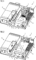
- FIG. 1 each show a perspective view of a computer system 1 according to an exemplary embodiment of the invention.
- figure 1 shows the computer system 1 in a first system configuration A
- figure 2 shows the computer system 1 in a second system configuration B.
- the first system configuration A according to FIG figure 1 is characterized in that two low-profile circuit boards 2 are installed in the computer system 1.
- the second system configuration B according to figure 2 is characterized in that a low-profile board 2 and a full-height board 3 are installed in the computer system 1.
- the computer system 1 each includes a housing 4.
- the housing 4 is a housing with a small form factor (SFF), which has a volume of approximately 8l.
- SFF small form factor
- the housing 4 has a housing base 5 .
- a first housing wall 6 and a second housing wall 7 protrude perpendicularly from the housing floor 5 on opposite side edges of the housing floor 5 .
- the computer system 1 can be closed with a housing cover, not shown here.
- a system circuit board 8 is fitted in the computer system 1 parallel to the housing base 5 .
- the system circuit board 8 is located in an area of the housing base 5 and is attached to the housing base by means of screws that are not shown here.
- On the system board 8 are different Components such as memory modules 9, a processor 10, and a heat sink 11 attached.
- a first recess 12 and a second recess 13 are located in the first housing wall 6.
- the first and second recesses 12, 13 each extend in the form of a slot from an end of the first housing wall 6 facing away from the housing base 5, perpendicularly to the system circuit board 8.
- the first and the second recess 12, 13 each have a low-profile circuit board 2 attached.
- the low-profile circuit boards 2 each have a slot bracket 14, by means of which the low-profile circuit boards 2 are fastened in the first and second recesses 12, 13, respectively.
- the low-profile circuit boards 2 are arranged perpendicular to the system circuit board 8 and plugged onto the system circuit board 8 .
- the low-profile circuit boards 2 have different lengths. Alternatively, of course, low-profile circuit boards 2 of the same length can also be used.
- a low-profile circuit board 2 is fixed only in the second recess 13 .
- a holding device 15 for a full-height circuit board 3 is fitted in the first recess 12 .
- the cooling ribs of the heat sink 11 have corresponding recesses.
- the holding device 15 has a fastening part 16 by means of which the holding device 15 is fastened in the first recess 12 .
- the holding device 15 has a Circuit board holder 17 on which the full-height circuit board 3 is attached to the holding device 15 by means of a slot bracket 18 of the full-height circuit board 3 .
- the circuit board holder 17 is designed in a triangular shape over a side of the full-height circuit board 3 facing away from the system circuit board 8 , which serves to reinforce and protect the circuit board 3 .
- the circuit board holder 17 is mounted in an opening 19 in the first housing wall 6 .
- the opening 19 adjoins the first recess 12 and is open at an end of the first housing wall 6 facing away from the housing base 5 .
- the opening 19, in which the circuit board holder 17 is mounted extends parallel to the system circuit board 8, perpendicular to the first and second recesses 12, 13. Accordingly, the slot cover 18 of the full-height circuit board 3, and thus also the full Height board itself, mounted in parallel with the system board 8 in the computer system 1.
- the opening 19 is in the first system configuration A according to figure 1 covered by a removable part 20 of the first housing wall 6.
- the detachable part 20 is attached to the remaining first housing wall 6 by means of screws, not shown here.
- the detachable part 20 can also be attached to the remaining first housing wall 6 by means of a clip connection.
- the detachable part 20 can be separated from the rest of the first housing wall 6 and attached to it again. This enables a flexible change between the first system configuration A and the second system configuration B.
- the detachable part 20 represents a screen which is made of sheet metal, for example, and seals the opening 19 against electromagnetic radiation. Alternatively, the screen can also be made of plastic. An alternative embodiment to this is regarding figure 5 described.
- the detachable part 20 protects an interior of the housing 4 in a region of the opening 19 from penetrating dust, and the housing 4 is shielded from electromagnetic radiation.
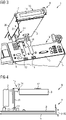
- figure 3 shows a partially exploded representation of a section of the computer system 1 according to the exemplary embodiment according to FIGS Figures 1 and 2 in the second system configuration B.
- the cutout in figure 3 shows the housing bottom 5 and part of the first housing wall 6 with the second recess 13 and the first recess 12 with the holding device 15.
- the fastening part 16, with which the holding device 15 is fastened in the first cutout 12, essentially resembles a lower end of a slot bracket of a low-profile board 2 and is fastened to the board holder 17 of the holding device 15 by means of screws (not shown here).
- the fastening part 16 is not fastened to the circuit board holder 17 by means of screws, but is loosely connected to the circuit board holder 17, for example, via a plug-in connection or simply via a bearing contact.
- the fastening part 16 serves, among other things, to seal the first cutout 12 against electromagnetic radiation when the holding device 15 is fitted in the first cutout 12 . Furthermore, it is possible in the fastening part 16 to have an I/O interface (input/output interface), For example, to arrange a socket for a data interface.
- This I/O interface can be an I/O interface that is connected to the full-height board 3 or another I/O interface of the computer system 1.
- connection part 21 of the holding device 15 can also be seen.
- This connection part 21 extends perpendicularly to the full-height board 3 in the direction of the system board 8.
- the connection part 21 is parallel to the low-profile board 2, as shown in FIG figure 2 is shown.
- the connection part 21 represents a so-called riser card for the full-height circuit board 3.
- connection part 21 At one end of the connection part 21 facing the system circuit board 8, the connection part 21 has a connector 22 according to the PCI or PCIe standard, so that the connection part 21 with the connector 22 can be plugged into a mating connector provided for this purpose on the system circuit board 8. This is explained in more detail below with reference to figure 4 explained.
- figure 4 shows a section through the computer system 1 according to the exemplary embodiment according to FIG Figures 1 and 2 in the second system configuration B.
- figure 5 shows a sectional plane parallel to the first housing wall 6 along a in the figure 2 shown cutting line S.
- FIG. 4 In the sectional view according to figure 4 a part of the housing floor 5 and the system board 8 is shown. Also shows figure 5 the low-profile board 2 and the full-height board 3, which is mounted in the board holder 17. Furthermore, the is perpendicular to the system board 8 standing connection part 21 shown. In figure 4 a mounting plate 29 is also shown to the left of the connection part 21, which is part of a mechanical fastening of the holding device 15.
- figure 4 also shows the connector 22 of the connection part 21, which is plugged into the mating connector 23 on the system circuit board 8.
- connection part 21 At one end of the connection part 21 facing the full-height circuit board 3, this has a mating connector 25 according to the PCI or PCIe standard. A corresponding connector 24 of the full-height circuit board 3 is plugged into this mating connector 25 of the connection part 21 . In this way, an electrical connection for supply voltages, signals, etc. is established between the system circuit board 8 and the full-height circuit board 3 via the connection part 21 .
- figure 5 shows a section of the first housing wall 6 in an area of the opening 19 with part of the first recess 12.
- figure 5 shows a view of the first housing wall 6 from inside the housing 4 of the computer system 1.
- figure 5 shows an alternative embodiment to the detachable part 20 and the opening 19.
- FIG figure 5 The state shown corresponds to the first system configuration A, according to which a low-profile circuit board 2 can be fastened in the first recess 12 .
- the opening 19 is covered with a part 26 that can be broken out.
- the part 26 that can be broken off has a tab 27 on an edge area of the first housing wall 6, to which a slot bracket 14 of a low-profile circuit board 2 can be attached. If a full-height circuit board 3 is to be installed in the first recess 12 in the housing 4, the part 26 that can be broken out can be broken out of the housing wall 6.
- the housing wall 6 has a predetermined breaking line 28 along which the part 26 that can be broken off can be detached from the first housing wall 6 .
- FIG. 5 a projection provided along an upper edge of the opening 19. This projection points into the interior of the housing 4 and provides a support for the holding device 15. This projection can be identical in the exemplary embodiment according to FIG Figures 1 to 4 be used.
- each comprising a first and a second recess 12, 13 are to be understood merely as examples.
- the housing 4 or the first housing wall 6 can also have only the first recess 12 or other recesses similar to the first or the second recess 12, 13.
Landscapes
- Engineering & Computer Science (AREA)
- Theoretical Computer Science (AREA)
- Microelectronics & Electronic Packaging (AREA)
- Computer Hardware Design (AREA)
- General Engineering & Computer Science (AREA)
- Power Engineering (AREA)
- Human Computer Interaction (AREA)
- Physics & Mathematics (AREA)
- General Physics & Mathematics (AREA)
- Casings For Electric Apparatus (AREA)
- Mounting Of Printed Circuit Boards And The Like (AREA)
Description
- Die vorliegende Erfindung betrifft ein Computersystem umfassend ein Gehäuse mit wenigstens einer Gehäusewand, wobei die wenigstens eine Gehäusewand eine Aussparung zur Anbringung einer Zusatzplatine aufweist. Ferner betrifft die Erfindung eine Haltevorrichtung und ein Montageverfahren für eine Zusatzplatine in einem Computersystem.
- Computergehäuse weisen gewöhnlich Aussparungen in Gehäusewänden auf, in denen Zusatzplatinen, wie beispielsweise PCI-(Peripheral Component Interconnect) bzw. PCIe-(Peripheral Component Interconnect Express) Karten, in ein Computersystem eingebaut werden können. Bei solchen PCI- bzw. PCIe-Karten handelt es sich beispielsweise um Netzwerkkarten oder Grafikkarten. Derartige Zusatzplatinen weisen unterschiedliche Formfaktoren auf. So gibt es beispielsweise so genannter Low-Profile-Platinen, deren Slotblenden eine Höhe von 79,2 mm aufweisen. Ferner gibt es beispielsweise sogenannte Full-Height-Platinen, deren Slotblenden eine Höhe von 120 mm aufweisen. Je nachdem, ob eine Zusatzplatine gemäß dem Low-Profile- oder dem Full-Height-Formfaktor eingebaut werden soll, müssen die Gehäuse unterschiedliche Aussparungen zum Befestigen der Zusatzplatinen aufweisen. Dies hat einen hohen Produktionsaufwand zur Folge, da je nach Bedarf unterschiedliche Gehäuse produziert werden müssen. Außerdem führt dies zu einer geringen Flexibilität beim Nachrüsten von Zusatzkarten mit unterschiedlichen Formfaktoren.
- Die
WO 2015/007045 A1 bezieht sich auf ein Computergerät, insbesondere auf eine Struktur zur Installation von - Erweiterungskarten und einen All-in-One-Computer, gemäß dem Oberbegriff des Patentanspruchs 1.
-
CN 101 236 450 A bezieht sich auf Computer, und zwar insbesondere auf ein Computersystem, das Erweiterungskarten mit unterschiedlichen Höhenprofilen aufnehmen kann. - Aufgabe der vorliegenden Erfindung ist es, die oben genannten Probleme zu lösen oder zu mindern.
- Gemäß einem ersten Aspekt wird die oben genannte Aufgabe durch ein Computersystem umfassend ein Gehäuse mit wenigstens einer Gehäusewand gelöst. Die wenigstens eine Gehäusewand weist eine erste Aussparung zur Anbringung einer ersten Zusatzplatine mit einem ersten Höhenprofil auf. Das Computersystem umfasst des Weiteren eine in dem Gehäuse angeordnete, sich senkrecht zu der wenigstens einen Gehäusewand erstreckende Systemplatine. Die erste Aussparung in der wenigstens einen Gehäusewand erstreckt sich senkrecht zu der Systemplatine. Außerdem umfasst das Computersystem eine Haltevorrichtung, die dazu eingerichtet ist, in der ersten Aussparung befestigt zu werden und eine zweite Zusatzplatine mit einem zweiten Höhenprofil parallel zu der Systemplatine in dem Computersystem zu befestigen. Die wenigstens eine Gehäusewand weist eine an die erste Aussparung anschließende Öffnung auf, in der ein sich parallel zur wenigstens einen Gehäusewand erstreckender Teil der Haltevorrichtung lagerbar ist. Die Öffnung ist dazu eingerichtet, mit einer Blende abgedeckt zu werden, wenn das Computersystem dazu eingerichtet ist, die erste Zusatzplatine mit dem ersten Höhenprofil in der ersten Aussparung anzubringen.
- Vorteilhaft hierbei ist es, dass in der ersten Aussparung der Gehäusewand Zusatzplatinen mit unterschiedlichen Höhenprofilen befestigt werden können. Insbesondere können so sowohl Low-Profile-Platinen als auch Full-Height-Platinen in einer für Low-Profile-Platinen vorgesehenen Aussparung befestigt werden. Je nach Wunsch eines Benutzers des Computersystems kann eine entsprechende Zusatzplatine eingebaut werden, ohne dass unterschiedlich ausgestaltete Gehäuse angefertigt werden müssen.
- Weiterhin weist die wenigstens eine Gehäusewand eine an die erste Aussparung anschließende Öffnung auf, in der ein sich parallel zur wenigstens einen Gehäusewand erstreckender Teil der Haltevorrichtung lagerbar ist. Die Öffnung ist dazu eingerichtet, mit einer Blende abgedeckt zu werden, wenn das Computersystem dazu eingerichtet ist, die erste Zusatzplatine mit dem ersten Höhenprofil in der ersten Aussparung anzubringen.
- Beispielsweise eignen sich als Blende geschraubte oder geclipste Blechteile oder Kunststoffteile. Ein Vorteil einer derartigen Blende ist es, dass sie flexibel abgenommen und wieder angebracht werden kann, in Abhängigkeit davon, ob eine Zusatzplatine mit dem ersten oder dem zweiten Höhenprofil in dem Computersystem eingebaut ist.
- In wenigstens einer Ausgestaltung entspricht eine Höhe der Haltevorrichtung senkrecht zu der Systemplatine einer Höhe der ersten Zusatzplatine. Ferner weist die Haltevorrichtung einen Befestigungsteil für die zweite Zusatzplatine auf, der an einem der Systemplatine abgewandten Ende der Haltevorrichtung angeordnet ist.
- Ein Vorteil hierbei ist es, dass die zweite Zusatzplatine, welche parallel zu der Systemplatine in dem Computersystem befestigt werden kann, möglichst weit von der Systemplatine entfernt angebracht ist. Dies gewährleistet eine gute Kühlung der Systemplatine, der zweiten Zusatzplatine sowie weiterer in dem Computersystem angebrachter Komponenten. Außerdem wird auf diese Weise möglichst viel Platz zum Anbringen von Komponenten auf der Systemplatine gewährleistet, auch wenn die zweite Zusatzplatine in dem Computersystem eingebaut ist.
- In wenigstens einer Ausgestaltung weist die wenigstens eine Gehäusewand wenigstens eine zweite Aussparung auf, die dazu eingerichtet ist, eine erste Zusatzplatine mit einem ersten Höhenprofil aufzunehmen, während in der ersten Aussparung die Haltevorrichtung befestigt ist.
- So können verschiedene Zusatzplatinen mit unterschiedlichen Formfaktoren in dem Computersystem eingebaut werden. Insbesondere kann, zum Beispiel, eine Zusatzplatine gemäß dem Low-Profile-Standard und eine Zusatzplatine gemäß dem Full-Height-Standard eingebaut werden.
- In wenigstens einer Ausgestaltung umfasst die wenigstens eine Gehäusewand einen an die erste Aussparung anschließenden ausbrechbaren Teil, der dazu eingerichtet ist, eine Öffnung freizugeben, in der ein sich parallel zur wenigstens einen Gehäusewand erstreckende Teil der Haltevorrichtung lagerbar ist.
- Vorteilhaft hierbei ist es, dass ein Gehäuse mit einem solchen ausbrechbaren Teil verhältnismäßig einfach und kostengünstig zu produzieren ist.
- Gemäß einem zweiten Aspekt wird die oben genannte Aufgabe durch eine Haltevorrichtung gelöst, die dazu eingerichtet ist, in einer in einer Gehäusewand eines Gehäuses eines Computersystems angeordneten Aussparung für eine erste Zusatzplatine mit einem ersten Höhenprofil befestigt zu werden und eine zweite Zusatzplatine mit einem zweiten Höhenprofil parallel zu einer in dem Gehäuse des Computersystems angeordneten Systemplatine in dem Computersystem zu befestigen.
- Gemäß einem dritten Aspekt wird die oben genannte Aufgabe durch ein Montageverfahren für eine Zusatzplatine in einem Computersystem umfassend ein Gehäuse mit wenigstens einer Gehäusewand, wobei die wenigstens eine Gehäusewand eine erste Aussparung zur Anbringung einer ersten Zusatzplatine mit einem ersten Höhenprofil aufweist, wobei sich die erste Aussparung in der wenigsten einen Gehäusewand senkrecht zu einer in dem Gehäuse angeordnete, sich senkrecht zu der wenigstens einen Gehäusewand erstreckende Systemplatine erstreckt, gelöst. Das
- Montageverfahren umfasst die folgenden Schritte:
- Entfernen eines an die erste Aussparung anschließenden entfernbaren Teils von der wenigstens einen Gehäusewand so dass sich eine Öffnung in der wenigstens einen ersten Gehäusewand ergibt;
- Befestigen einer Haltevorrichtung für eine zweite Zusatzplatine in der ersten Aussparung, so dass ein sich parallel zur wenigstens einen Gehäusewand erstreckender Teil der Haltevorrichtung in der Öffnung gelagert ist;
- Befestigen der zweiten Zusatzplatine mit einem zweiten Höhenprofil parallel zu einer in dem Gehäuse des Computersystems angeordnete Systemplatine an der Haltevorrichtung.
- Vorteile des zweiten und dritten Aspekts entsprechen im Wesentlichen den Vorteilen des ersten Aspekts. Der entfernbare Teil der wenigstens einen Gehäusewand kann beispielsweise ein ausbrechbarer Teil sein, der aus der wenigstens einen Gehäusewand ausgebrochen wird, oder eine abnehmbare Blende sein, die beispielsweise aus Blech oder Kunststoff gefertigt ist und an der wenigstens einen Gehäusewand beispielsweise mittels Schrauben oder Clipverbindungen befestigbar ist.
- Weitere vorteilhafte Ausgestaltungen sind in den angehängten Ansprüchen sowie der nachfolgenden Beschreibung der Figuren offenbart. In den Figuren werden für Elemente mit im Wesentlichen gleicher Funktion gleiche Bezugszeichen verwendet, diese Elemente müssen jedoch nicht in allen Einzelheiten identisch sein.
- In den Figuren zeigen:
- Figur 1
- eine perspektivische Darstellung eines Computersystems gemäß einem Ausführungsbeispiel der Erfindung in einer ersten Systemkonfiguration,
- Figur 2
- eine perspektivische Darstellung des Computersystems gemäß dem Ausführungsbeispiel gemäß
Figur 1 in einer zweiten Systemkonfiguration, - Figur 3
- eine teilweise explodierte Darstellung eines Ausschnitts des Computersystems gemäß der zweiten Systemkonfiguration gemäß
Figur 2 , - Figur 4
- einen Querschnitt eines Ausschnitts des Computersystems gemäß der zweiten Systemkonfiguration gemäß
Figur 2 , und - Figur 5
- einen Ausschnitt einer ersten Gehäusewand eines Computersystems gemäß einem Ausführungsbeispiel der Erfindung.
- Die
Figuren 1 und 2 zeigen jeweils eine perspektivische Ansicht eines Computersystems 1 gemäß einem Ausführungsbeispiel der Erfindung.Figur 1 zeigt das Computersystem 1 in einer ersten Systemkonfiguration A,Figur 2 zeigt das Computersystem 1 in einer zweiten Systemkonfiguration B. Die erste Systemkonfiguration A gemäßFigur 1 ist dadurch gekennzeichnet, dass zwei Low-Profile-Platinen 2 in dem Computersystem 1 eingebaut sind. Die zweite Systemkonfiguration B gemäßFigur 2 ist dadurch gekennzeichnet, dass eine Low-Profile-Platine 2 und eine Full-Height-Platine 3 in dem Computersystem 1 eingebaut sind. - Das Computersystem 1 gemäß der
Figuren 1 und 2 umfasst jeweils ein Gehäuse 4. Das Gehäuse 4 ist in diesem Ausführungsbeispiel ein Gehäuse mit kleinem Formfaktor (englisch: small form factor, SFF), welches ein Volumen von ca. 8l fasst. Alternativ kann die hier beschriebene Erfindung natürlich auch in jedem beliebigen Computergehäuse verwendet werden. Das Gehäuse 4 weist einen Gehäuseboden 5 auf. An gegenüberliegenden Seitenkanten des Gehäusebodens 5 stehen senkrecht von dem Gehäuseboden 5 eine erste Gehäusewand 6 sowie eine zweite Gehäusewand 7 ab. Das Computersystem 1 ist mit einem hier nicht gezeigten Gehäusedeckel verschließbar. - Parallel zu dem Gehäuseboden 5 ist in dem Computersystem 1 eine Systemplatine 8 angebracht. Die Systemplatine 8 befindet sich in einem Bereich des Gehäusebodens 5 und ist an dem Gehäuseboden mittels hier nicht gezeigter Schrauben befestigt. Auf der Systemplatine 8 sind verschiedene Komponenten, wie beispielsweise Speichermodule 9, ein Prozessor 10, sowie ein Kühlkörper 11 angebracht.
- In der ersten Gehäusewand 6 befinden sich eine erste Aussparung 12 und eine zweite Aussparung 13. Erste und zweite Aussparung 12, 13 erstrecken sich jeweils schlitzförmig von einem dem Gehäuseboden 5 abgewandten Ende der ersten Gehäusewand 6 senkrecht zu der Systemplatine 8.
- Gemäß der ersten Systemkonfiguration A gemäß
Figur 1 sind in der ersten und der zweiten Aussparung 12, 13 jeweils eine Low-Profile-Platine 2 befestigt. Die Low-Profile-Platinen 2 weisen jeweils eine Slotblende 14 auf, mittels der die Low-Profile-Platinen 2 in der ersten bzw. zweiten Aussparung 12, 13 befestigt sind. Die Low-Profile-Platinen 2 sind senkrecht zu der Systemplatine 8 angeordnet und auf die Systemplatine 8 gesteckt. Die Low-Profile-Platinen 2 weisen in diesem Ausführungsbeispiel unterschiedliche Längen auf. Alternativ können selbstverständlich auch gleich lange Low-Profile-Platinen 2 verwendet werden. - Gemäß der zweiten Systemkonfiguration B gemäß
Figur 2 ist nur in der zweiten Aussparung 13 eine Low-Profile-Platine 2 befestigt. Gemäß der zweiten Systemkonfiguration B ist in der ersten Aussparung 12 eine Haltevorrichtung 15 für eine Full-Height-Platine 3 angebracht. Um in dem Computersystem 1 ausreichend Platz für die Full-Height-Platine 3 bereitzustellen weisen Kühlrippen des Kühlkörpers 11 entsprechende Aussparungen auf. - Die Haltevorrichtung 15 weist einen Befestigungsteil 16 auf, mittels dem die Haltevorrichtung 15 in der ersten Aussparung 12 befestigt ist. Außerdem weist die Haltevorrichtung 15 eine Platinenhalterung 17 auf, an der die Full-Height-Platine 3 mittels einer Slotblende 18 der Full-Height-Platine 3 an der Haltevorrichtung 15 befestigt ist. Die Platinenhalterung 17 ist über einer der Systemplatine 8 abgewandten Seite der Full-Height-Platine 3 in einer Dreiecksform ausgestaltet, was einer Verstärkung und einem Schutz der Platine 3 dient.
- Die Platinenhalterung 17 ist in einer Öffnung 19 der ersten Gehäusewand 6 gelagert. Die Öffnung 19 schließt sich an die erste Aussparung 12 an und ist an einem dem Gehäuseboden 5 abgewandten Ende der ersten Gehäusewand 6 offen. Die Öffnung 19, in der die Platinenhalterung 17 gelagert ist, erstreckt sich parallel zu der Systemplatine 8, senkrecht zu der ersten und zweiten Aussparung 12, 13. Demzufolge ist die Slotblende 18 der Full-Height-Platine 3, und somit auch die Full-Height-Platine selbst, parallel zu der Systemplatine 8 in dem Computersystem 1 befestigt.
- Die Öffnung 19 ist in der ersten Systemkonfiguration A gemäß
Figur 1 durch einen abnehmbaren Teil 20 der ersten Gehäusewand 6 abgedeckt. Der abnehmbare Teil 20 ist an der restlichen ersten Gehäusewand 6 mittels hier nicht gezeigter Schrauben befestigt. Alternativ kann der abnehmbare Teil 20 auch an der restlichen ersten Gehäusewand 6 mittels einer Clipverbindung befestigt sein. Somit kann der abnehmbare Teil 20 von der restlichen ersten Gehäusewand 6 getrennt und an dieser wieder befestigt werden. Dies ermöglicht ein flexibles wechseln zwischen der ersten Systemkonfiguration A und der zweiten Systemkonfiguration B. Der abnehmbare Teil 20 stellt eine Blende dar, die beispielsweise aus Blech gefertigt ist und die Öffnung 19 gegen elektromagnetische Strahlung abdichtet. Die Blende kann alternativ auch aus Kunststoff gefertigt sein. Eine alternative Ausgestaltung hierzu wird mit Bezug aufFigur 5 beschrieben. Durch den abnehmbaren Teil 20 wird in der ersten Systemkonfiguration A ein Inneres des Gehäuses 4, in einem Bereich der Öffnung 19, vor eindringenden Staub geschützt, sowie das Gehäuse 4 gegenüber elektromagnetischer Strahlung geschirmt. - Weitere Details bezüglich der Haltevorrichtung 15 werden mit Bezug auf die
Figuren 3 und 4 beschrieben. -
Figur 3 zeigt eine teilweise explodierte Darstellung eines Ausschnitts des Computersystems 1 gemäß dem Ausführungsbeispiel gemäß denFiguren 1 und 2 in der zweiten Systemkonfiguration B. Der Ausschnitt inFigur 3 zeigt den Gehäuseboden 5 sowie einen Teil der ersten Gehäusewand 6 mit der zweiten Aussparung 13 und der ersten Aussparung 12 mit der Haltevorrichtung 15. - Der Befestigungsteil 16, mit dem die Haltevorrichtung 15 in der ersten Aussparung 12 befestigt wird, gleicht im Wesentlichen einem unteren Ende einer Slotblende einer Low-Profile-Platine 2 und ist mittels hier nicht gezeigter Schrauben an der Platinenhalterung 17 der Haltevorrichtung 15 befestigt. Alternativ ist der Befestigungsteil 16 nicht mittels Schrauben an der Platinenhalterung 17 befestigt, sondern beispielsweise über eine Steckverbindung oder lediglich über einen Auflagekontakt lose mit der Platinenhalterung 17 verbunden.
- Der Befestigungsteil 16 dient unter anderem dazu, die erste Aussparung 12 gegen elektromagnetische Strahlung abzudichten, wenn die Haltevorrichtung 15 in der ersten Aussparung 12 angebracht ist. Des Weiteren ist es möglich, in dem Befestigungsteil 16 eine I/O-Schnittstelle (Input/Output-Schnittstelle), beispielsweise eine Buchse für eine Datenschnittstelle, anzuordnen. Diese I/O-Schnittstelle kann eine I/O-Schnittstelle, die an die Full-Height-Platine 3 angeschlossen ist, oder eine sonstige I/O-Schnittstelle des Computersystems 1 sein.
- In der
Figur 3 ist des Weiteren ein Anschlussteil 21 der Haltevorrichtung 15 zu sehen. Dieser Anschlussteil 21 erstreckt sich senkrecht zu der Full-Height-Platine 3 in Richtung Systemplatine 8. Im eingebauten Zustand liegt der Anschlussteil 21 parallel zu der Low-Profile-Platine 2, wie sie inFigur 2 gezeigt ist. Der Anschlussteil 21 stellt für die Full-Height-Platine 3 eine sogenannte Riser-Karte dar. - An einem der Systemplatine 8 zugewandten Ende des Anschlussteils 21 weist der Anschlussteil 21 einen Steckverbinder 22 gemäß dem PCI- bzw. PCIe-Standard auf, sodass der Anschlussteil 21 mit dem Steckverbinder 22 in einen dafür vorgesehenen Gegensteckverbinder auf der Systemplatine 8 eingesteckt werden kann. Dies wird im Folgenden näher mit Bezug auf
Figur 4 erläutert. -
Figur 4 zeigt einen Schnitt durch das Computersystem 1 gemäß dem Ausführungsbeispiel gemäß derFiguren 1 und 2 in der zweiten Systemkonfiguration B.Figur 5 zeigt eine Schnittebene parallel zur ersten Gehäusewand 6 entlang einer in derFigur 2 gezeigten Schnittlinie S. - In der Schnittdarstellung gemäß
Figur 4 ist ein Teil des Gehäusebodens 5 und der Systemplatine 8 gezeigt. Außerdem zeigtFigur 5 die Low-Profile-Platine 2 sowie die Full-Height-Platine 3, die in der Platinenhalterung 17 gelagert ist. Des Weiteren ist der senkrecht auf die Systemplatine 8 stehende Anschlussteil 21 gezeigt. InFigur 4 ist links neben dem Anschlussteil 21 ferner eine Montageplatte 29 gezeigt, die Teil einer mechanischen Befestigung der Haltevorrichtung 15 ist. -
Figur 4 zeigt ferner den Steckverbinder 22 des Anschlussteils 21, der in den Gegensteckverbinder 23 auf der Systemplatine 8 gesteckt ist. Der Gegensteckverbinder 23, der den Steckverbinder 22 in der zweiten Systemkonfiguration B aufnimmt, nimmt in der ersten Systemkonfiguration A einen entsprechenden Steckverbinder der Low-Profile-Platine, die in der ersten Aussparung befestigt ist, auf. - An einem der Full-Height-Platine 3 zugewandten Ende des Anschlussteils 21 weist dieser einen Gegensteckverbinder 25 gemäß dem PCI- bzw. PCIe-Standard auf. In diesen Gegensteckverbinder 25 des Anschlussteils 21 wird ein entsprechender Steckverbinder 24 der Full-Height-Platine 3 eingesteckt. Auf diese Weise wird eine elektrische Verbindung für Versorgungsspannungen, Signale, etc. zwischen der Systemplatine 8 und der Full-Height-Platine 3 über den Anschlussteil 21 hergestellt.
-
Figur 5 zeigt einen Ausschnitt der ersten Gehäusewand 6 in einem Bereich der Öffnung 19 mit einem Teil der ersten Aussparung 12.Figur 5 zeigt einen Blick auf die erste Gehäusewand 6 aus einem Inneren des Gehäuses 4 des Computersystems 1.Figur 5 zeigt eine alternative Ausgestaltung zu dem abnehmbaren Teil 20 und der Öffnung 19. Der inFigur 5 gezeigte Zustand entspricht der ersten Systemkonfiguration A, gemäß der eine Low-Profile-Platine 2 in der ersten Aussparung 12 befestigbar ist. - Die Öffnung 19 ist in diesem Ausführungsbeispiel mit einem ausbrechbaren Teil 26 abgedeckt. Der ausbrechbare Teil 26 weist an einem Randbereich der ersten Gehäusewand 6 eine Lasche 27 auf, an der eine Slotblende 14 einer Low-Profile-Platine 2 befestigt werden kann. Soll in dem Gehäuse 4 eine Full-Height-Platine 3 in der ersten Aussparung 12 eingebaut werden, so kann der ausbrechbare Teil 26 aus der Gehäusewand 6 ausgebrochen werden. Hierfür weist die Gehäusewand 6 eine Sollbruchlinie 28 auf, entlang der der ausbrechbare Teil 26 von der ersten Gehäusewand 6 gelöst werden kann.
- Zusätzlich zeigt
Figur 5 einen entlang einer Oberkante der Öffnung 19 angebrachten Vorsprung. Dieser Vorsprung weist ins Innere des Gehäuses 4 und stellt eine Auflage für die Haltevorrichtung 15 dar. Dieser Vorsprung kann identisch in dem Ausführungsbeispiel gemäß derFiguren 1 bis 4 verwendet werden. - Die in den Figuren gezeigten Ausführungsbeispiele umfassend jeweils eine erste und eine zweite Aussparung 12, 13 sind lediglich beispielhaft zu verstehen. Alternativ kann das Gehäuse 4 bzw. die erste Gehäusewand 6 auch nur die erste Aussparung 12 oder weitere, der ersten bzw. der zweiten Aussparung 12, 13 ähnliche Aussparungen aufweisen.
-
- 1
- Computersystem
- 2
- Low-Profile-Platine
- 3
- Full-Height-Platine
- 4
- Gehäuse
- 5
- Gehäuseboden
- 6
- erste Gehäusewand
- 7
- zweiter Gehäusewand
- 8
- Systemplatine
- 9
- Speichermodul
- 10
- Prozessor
- 11
- Kühlkörper
- 12
- erste Aussparung
- 13
- zweite Aussparung
- 14
- Slotblende der Low-Profile-Platine
- 15
- Haltevorrichtung
- 16
- Befestigungsteil
- 17
- Platinenhalterung
- 18
- Slotblende der Full-Height-Platine
- 19
- Öffnung
- 20
- abnehmbarer Teil
- 21
- Anschlussteil
- 22
- Steckverbinder
- 23
- Gegensteckverbinder
- 24
- Steckverbinder
- 25
- Gegensteckverbinder
- 26
- ausbrechbarer Teil
- 27
- Lasche
- 28
- Sollbruchlinie
- 29
- Montageplatte
- A
- erste Systemkonfiguration
- B
- zweite Systemkonfiguration
- S
- Schnittlinie
Claims (8)
- Computersystem (1), umfassend- ein Gehäuse (4) mit wenigstens einer Gehäusewand (6), wobei die wenigstens eine Gehäusewand (6) eine erste Aussparung (12) zur Anbringung einer ersten Zusatzplatine mit einem ersten Höhenprofil aufweist;- eine in dem Gehäuse (4) angeordnete, sich senkrecht zu der wenigstens einen Gehäusewand (6) erstreckende Systemplatine (8), wobei sich die erste Aussparung (12) in der wenigstens einen Gehäusewand (6) senkrecht zu der Systemplatine (8) erstreckt;- eine Haltevorrichtung (15), die dazu eingerichtet ist, in der ersten Aussparung (12) befestigt zu werden und eine zweite Zusatzplatine mit einem zweiten Höhenprofil parallel zu der Systemplatine (8) in dem Computersystem (1) zu befestigen; dadurch gekennzeichnet, dass die wenigstens eine Gehäusewand (6) eine an die erste Aussparung (12) anschließende Öffnung (19) aufweist, in der ein sich parallel zur wenigstens einen Gehäusewand (6) erstreckender Teil der Haltevorrichtung (15) lagerbar ist, und wobei die Öffnung (19) dazu eingerichtet ist, mit einer Blende abgedeckt zu werden, wenn das Computersystem (1) dazu eingerichtet ist, die erste Zusatzplatine mit dem ersten Höhenprofil in der ersten Aussparung (12) anzubringen.
- Computersystem (1) gemäß Anspruch 1, wobei die erste Zusatzplatine und die zweite Zusatzplatine jeweils PCI- und/oder PCIe-Platinen sind.
- Computersystem (1) gemäß Anspruch 2, wobei- die erste Zusatzplatine eine Low-Profile-Platine (2) ist,- die zweite Zusatzplatine eine Full-Height-Platine (3) ist, und- die erste Aussparung (12) ein Low-Profile-Slot ist.
- Computersystem (1) gemäß einem der Ansprüche 1 bis 3, wobei eine Höhe der Haltevorrichtung (15) senkrecht zu der Systemplatine (8) einer Höhe der ersten Zusatzplatine entspricht und die Haltevorrichtung (15) ein Befestigungsteil (16) für die zweite Zusatzplatine aufweist, der an einem der Systemplatine (8) abgewandten Ende der Haltevorrichtung (15) angeordnet ist.
- Computersystem (1) gemäß einem der Ansprüche 1 bis 4, wobei die wenigstens eine Gehäusewand (6) wenigstens eine zweite Aussparung (13) aufweist, die dazu eingerichtet ist, eine erste Zusatzplatine mit einem ersten Höhenprofil aufzunehmen, während in der ersten Aussparung (12) die Haltevorrichtung (15) befestigt ist.
- Computersystem (1) gemäß einem der Ansprüche 1 bis 5, wobei die Haltevorrichtung (15) einen Anschlussteil (21) umfasst, der sich senkrecht zu der Systemplatine (8) und der wenigstens einen Gehäusewand (6) erstreckt und dazu eingerichtet ist, eine elektrische Verbindung zwischen der Systemplatine (8) und der zweiten Zusatzplatine herzustellen.
- Computersystem (1) gemäß einem der Ansprüche 1 bis 6, wobei die wenigstens eine Gehäusewand (6) einen an die erste Aussparung (12) anschließenden ausbrechbaren Teil (26) umfasst, der dazu eingerichtet ist, eine Öffnung (19) freizugeben, in der ein sich parallel zur wenigstens einen Gehäusewand (6) erstreckender Teil der Haltevorrichtung (15) lagerbar ist.
- Montageverfahren für eine Zusatzplatine in einem Computersystem (1) umfassend ein Gehäuse (4) mit wenigstens einer Gehäusewand (6), wobei die wenigstens eine Gehäusewand (6) eine erste Aussparung (12) zur Anbringung einer ersten Zusatzplatine mit einem ersten Höhenprofil aufweist, wobei sich die erste Aussparung in der wenigsten einen Gehäusewand senkrecht zu einer in dem Gehäuse angeordnete, sich senkrecht zu der wenigstens einen Gehäusewand erstreckende Systemplatine erstreckt, das Montageverfahren umfassend die folgenden Schritte:- Entfernen eines an die erste Aussparung (12) anschließenden entfernbaren Teils von der wenigstens einen Gehäusewand (6) so dass sich eine Öffnung (19) in der wenigstens einen ersten Gehäusewand (6) ergibt;- Befestigen einer Haltevorrichtung (15) für eine zweite Zusatzplatine in der ersten Aussparung (12), so dass ein sich parallel zur wenigstens einen Gehäusewand (6) erstreckender Teil der Haltevorrichtung (15) in der Öffnung (19) gelagert ist;- Befestigen der zweiten Zusatzplatine mit einem zweiten Höhenprofil parallel zur in dem Gehäuse (4) des Computersystems (1) angeordnete Systemplatine (8) an der Haltevorrichtung (15).
Applications Claiming Priority (2)
| Application Number | Priority Date | Filing Date | Title |
|---|---|---|---|
| DE102018117382.2A DE102018117382B3 (de) | 2018-07-18 | 2018-07-18 | Computersystem, Haltevorrichtung und Montageverfahren für eine Zusatzplatine in einem Computersystem |
| PCT/EP2019/061278 WO2020015879A1 (de) | 2018-07-18 | 2019-05-02 | Computersystem, haltevorrichtung und montageverfahren für eine zusatzplatine in einem computersystem |
Publications (2)
| Publication Number | Publication Date |
|---|---|
| EP3652609A1 EP3652609A1 (de) | 2020-05-20 |
| EP3652609B1 true EP3652609B1 (de) | 2022-06-29 |
Family
ID=66335463
Family Applications (1)
| Application Number | Title | Priority Date | Filing Date |
|---|---|---|---|
| EP19721287.1A Active EP3652609B1 (de) | 2018-07-18 | 2019-05-02 | Computersystem, haltevorrichtung und montageverfahren für eine zusatzplatine in einem computersystem |
Country Status (5)
| Country | Link |
|---|---|
| US (1) | US20200245479A1 (de) |
| EP (1) | EP3652609B1 (de) |
| JP (1) | JP6908869B2 (de) |
| DE (1) | DE102018117382B3 (de) |
| WO (1) | WO2020015879A1 (de) |
Family Cites Families (8)
| Publication number | Priority date | Publication date | Assignee | Title |
|---|---|---|---|---|
| JP3807765B2 (ja) * | 1995-12-20 | 2006-08-09 | 独立行政法人科学技術振興機構 | ポリアクリルアミド誘導体を有するブロック共重合体および温度応答性高分子ミセル |
| DE20109095U1 (de) | 2001-05-31 | 2002-10-02 | Faist Systeme GmbH, 86836 Untermeitingen | Montageadapter für Computersteckkarten mit geringer Bauhöhe |
| JP3937985B2 (ja) * | 2002-09-10 | 2007-06-27 | ソニー株式会社 | 電子部品実装組み込み機器及び電子部品実装基板の取付け方法 |
| CN101236450A (zh) * | 2008-01-25 | 2008-08-06 | 华为技术有限公司 | 计算机系统 |
| DE102009010469B4 (de) | 2009-02-26 | 2017-10-05 | Fujitsu Technology Solutions Intellectual Property Gmbh | Befestigungsanordnung und Adapterteil zur Befestigung einer Mehrzahl von Speicherlaufwerken |
| CN203366204U (zh) * | 2013-07-16 | 2013-12-25 | 谢浩然 | 扩展卡安装结构及一体机电脑 |
| US9740247B2 (en) * | 2014-03-29 | 2017-08-22 | Lenovo (Singapore) Pte. Ltd. | Card retention mechanism |
| DE102014112136B3 (de) | 2014-08-25 | 2015-12-17 | Fujitsu Technology Solutions Intellectual Property Gmbh | Gehäuse für ein Computersystem, Computersystem sowie Montageverfahren |
-
2018
- 2018-07-18 DE DE102018117382.2A patent/DE102018117382B3/de not_active Expired - Fee Related
-
2019
- 2019-05-02 EP EP19721287.1A patent/EP3652609B1/de active Active
- 2019-05-02 WO PCT/EP2019/061278 patent/WO2020015879A1/de not_active Ceased
- 2019-05-02 JP JP2020515140A patent/JP6908869B2/ja active Active
- 2019-05-02 US US16/756,700 patent/US20200245479A1/en not_active Abandoned
Also Published As
| Publication number | Publication date |
|---|---|
| JP2020533711A (ja) | 2020-11-19 |
| WO2020015879A1 (de) | 2020-01-23 |
| JP6908869B2 (ja) | 2021-07-28 |
| DE102018117382B3 (de) | 2019-05-16 |
| EP3652609A1 (de) | 2020-05-20 |
| US20200245479A1 (en) | 2020-07-30 |
Similar Documents
| Publication | Publication Date | Title |
|---|---|---|
| DE102014114790B3 (de) | Anordnung zur Festlegung wenigstens einer Erweiterungskarte und Serversystem | |
| DE102016223931B4 (de) | Substrathaltestruktur, elektronisches Bauelementmodul und Elektroanschlusskasten | |
| WO2004062329A1 (de) | Messgerätmodule und messgerät | |
| DE102016105322B3 (de) | Haltekomponente, Trägerkomponente und Anordnung | |
| DE102015101308B3 (de) | Haltevorrichtung, Anordnung mit einer Haltevorrichtung und Rackservereinschub | |
| DE102021206103B4 (de) | Vorrichtung | |
| DE102013200014B4 (de) | Elektronische Vorrichtung | |
| DE102023122649B4 (de) | Halterung für Leiterplattenmontage | |
| BE1030623B1 (de) | Vorrichtung und Verfahren für Gehäuse elektrischer Geräte | |
| DE102018117382B3 (de) | Computersystem, Haltevorrichtung und Montageverfahren für eine Zusatzplatine in einem Computersystem | |
| DE10326388A1 (de) | Messgerätmodule und Messgerät | |
| DE102020107646B4 (de) | Computer und Verfahren zum Festlegen einer Erweiterungskarte in einem Computer | |
| DE102009043656B4 (de) | I/O-Blende für ein Chassis eines Computersystems sowie Anordnung aus Chassis und I/O-Blende | |
| DE20109095U1 (de) | Montageadapter für Computersteckkarten mit geringer Bauhöhe | |
| EP1603381B1 (de) | Federblech in einem Gehäuse als Abschirmung für ein elektronisches hochfrequenztechnisches Gerät | |
| DE102005056953B3 (de) | Computergehäuse mit einem Abschirmblech mit mindestens einer Öffnung und Herstellungsverfahren für einen Computer | |
| DE112015006767T5 (de) | Gehäuse einer elektronischen Vorrichtung | |
| WO2009090016A1 (de) | Mobiles elektrisches gerät für fahrzeuge | |
| DE102023126884A1 (de) | Riser-käfig zur aufnahme eines steckers einer riser-karte | |
| DE202017104494U1 (de) | Computersystem | |
| DE29721480U1 (de) | Gehäuse für ein elektronisches Gerät | |
| DE112022007971T5 (de) | Anordnung und verfahren zum montieren eines bedienfelds | |
| DE102022114919A1 (de) | Vorrichtung und Verfahren für Gehäuse elektrischer Geräte | |
| EP1102527B1 (de) | Abschirmgehäuse mit ESD-Schutz | |
| EP1575347A1 (de) | Federblech in einem Gehäuse als Abschirmung für ein elektronisches hochfrequenztechnisches Gerät |
Legal Events
| Date | Code | Title | Description |
|---|---|---|---|
| STAA | Information on the status of an ep patent application or granted ep patent |
Free format text: STATUS: UNKNOWN |
|
| STAA | Information on the status of an ep patent application or granted ep patent |
Free format text: STATUS: THE INTERNATIONAL PUBLICATION HAS BEEN MADE |
|
| PUAI | Public reference made under article 153(3) epc to a published international application that has entered the european phase |
Free format text: ORIGINAL CODE: 0009012 |
|
| STAA | Information on the status of an ep patent application or granted ep patent |
Free format text: STATUS: REQUEST FOR EXAMINATION WAS MADE |
|
| 17P | Request for examination filed |
Effective date: 20200213 |
|
| AK | Designated contracting states |
Kind code of ref document: A1 Designated state(s): AL AT BE BG CH CY CZ DE DK EE ES FI FR GB GR HR HU IE IS IT LI LT LU LV MC MK MT NL NO PL PT RO RS SE SI SK SM TR |
|
| AX | Request for extension of the european patent |
Extension state: BA ME |
|
| DAV | Request for validation of the european patent (deleted) | ||
| DAX | Request for extension of the european patent (deleted) | ||
| GRAP | Despatch of communication of intention to grant a patent |
Free format text: ORIGINAL CODE: EPIDOSNIGR1 |
|
| STAA | Information on the status of an ep patent application or granted ep patent |
Free format text: STATUS: GRANT OF PATENT IS INTENDED |
|
| RIC1 | Information provided on ipc code assigned before grant |
Ipc: G06F 1/18 20060101AFI20211213BHEP |
|
| INTG | Intention to grant announced |
Effective date: 20220112 |
|
| GRAS | Grant fee paid |
Free format text: ORIGINAL CODE: EPIDOSNIGR3 |
|
| GRAA | (expected) grant |
Free format text: ORIGINAL CODE: 0009210 |
|
| STAA | Information on the status of an ep patent application or granted ep patent |
Free format text: STATUS: THE PATENT HAS BEEN GRANTED |
|
| RBV | Designated contracting states (corrected) |
Designated state(s): AL AT BE BG CH CY CZ DK EE ES FI FR GB GR HR HU IE IS IT LI LT LU LV MC MK MT NL NO PL PT RO RS SE SI SK SM TR |
|
| REG | Reference to a national code |
Ref country code: DE Ref legal event code: R108 |
|
| AK | Designated contracting states |
Kind code of ref document: B1 Designated state(s): AL AT BE BG CH CY CZ DK EE ES FI FR GB GR HR HU IE IS IT LI LT LU LV MC MK MT NL NO PL PT RO RS SE SI SK SM TR |
|
| REG | Reference to a national code |
Ref country code: CH Ref legal event code: EP |
|
| REG | Reference to a national code |
Ref country code: AT Ref legal event code: REF Ref document number: 1501772 Country of ref document: AT Kind code of ref document: T Effective date: 20220715 |
|
| REG | Reference to a national code |
Ref country code: IE Ref legal event code: FG4D Free format text: LANGUAGE OF EP DOCUMENT: GERMAN |
|
| REG | Reference to a national code |
Ref country code: LT Ref legal event code: MG9D |
|
| PG25 | Lapsed in a contracting state [announced via postgrant information from national office to epo] |
Ref country code: SE Free format text: LAPSE BECAUSE OF FAILURE TO SUBMIT A TRANSLATION OF THE DESCRIPTION OR TO PAY THE FEE WITHIN THE PRESCRIBED TIME-LIMIT Effective date: 20220629 Ref country code: NO Free format text: LAPSE BECAUSE OF FAILURE TO SUBMIT A TRANSLATION OF THE DESCRIPTION OR TO PAY THE FEE WITHIN THE PRESCRIBED TIME-LIMIT Effective date: 20220929 Ref country code: LT Free format text: LAPSE BECAUSE OF FAILURE TO SUBMIT A TRANSLATION OF THE DESCRIPTION OR TO PAY THE FEE WITHIN THE PRESCRIBED TIME-LIMIT Effective date: 20220629 Ref country code: HR Free format text: LAPSE BECAUSE OF FAILURE TO SUBMIT A TRANSLATION OF THE DESCRIPTION OR TO PAY THE FEE WITHIN THE PRESCRIBED TIME-LIMIT Effective date: 20220629 Ref country code: GR Free format text: LAPSE BECAUSE OF FAILURE TO SUBMIT A TRANSLATION OF THE DESCRIPTION OR TO PAY THE FEE WITHIN THE PRESCRIBED TIME-LIMIT Effective date: 20220930 Ref country code: FI Free format text: LAPSE BECAUSE OF FAILURE TO SUBMIT A TRANSLATION OF THE DESCRIPTION OR TO PAY THE FEE WITHIN THE PRESCRIBED TIME-LIMIT Effective date: 20220629 Ref country code: BG Free format text: LAPSE BECAUSE OF FAILURE TO SUBMIT A TRANSLATION OF THE DESCRIPTION OR TO PAY THE FEE WITHIN THE PRESCRIBED TIME-LIMIT Effective date: 20220929 |
|
| REG | Reference to a national code |
Ref country code: NL Ref legal event code: MP Effective date: 20220629 |
|
| PG25 | Lapsed in a contracting state [announced via postgrant information from national office to epo] |
Ref country code: RS Free format text: LAPSE BECAUSE OF FAILURE TO SUBMIT A TRANSLATION OF THE DESCRIPTION OR TO PAY THE FEE WITHIN THE PRESCRIBED TIME-LIMIT Effective date: 20220629 Ref country code: LV Free format text: LAPSE BECAUSE OF FAILURE TO SUBMIT A TRANSLATION OF THE DESCRIPTION OR TO PAY THE FEE WITHIN THE PRESCRIBED TIME-LIMIT Effective date: 20220629 |
|
| PG25 | Lapsed in a contracting state [announced via postgrant information from national office to epo] |
Ref country code: NL Free format text: LAPSE BECAUSE OF FAILURE TO SUBMIT A TRANSLATION OF THE DESCRIPTION OR TO PAY THE FEE WITHIN THE PRESCRIBED TIME-LIMIT Effective date: 20220629 |
|
| PG25 | Lapsed in a contracting state [announced via postgrant information from national office to epo] |
Ref country code: SM Free format text: LAPSE BECAUSE OF FAILURE TO SUBMIT A TRANSLATION OF THE DESCRIPTION OR TO PAY THE FEE WITHIN THE PRESCRIBED TIME-LIMIT Effective date: 20220629 Ref country code: SK Free format text: LAPSE BECAUSE OF FAILURE TO SUBMIT A TRANSLATION OF THE DESCRIPTION OR TO PAY THE FEE WITHIN THE PRESCRIBED TIME-LIMIT Effective date: 20220629 Ref country code: RO Free format text: LAPSE BECAUSE OF FAILURE TO SUBMIT A TRANSLATION OF THE DESCRIPTION OR TO PAY THE FEE WITHIN THE PRESCRIBED TIME-LIMIT Effective date: 20220629 Ref country code: PT Free format text: LAPSE BECAUSE OF FAILURE TO SUBMIT A TRANSLATION OF THE DESCRIPTION OR TO PAY THE FEE WITHIN THE PRESCRIBED TIME-LIMIT Effective date: 20221031 Ref country code: ES Free format text: LAPSE BECAUSE OF FAILURE TO SUBMIT A TRANSLATION OF THE DESCRIPTION OR TO PAY THE FEE WITHIN THE PRESCRIBED TIME-LIMIT Effective date: 20220629 Ref country code: EE Free format text: LAPSE BECAUSE OF FAILURE TO SUBMIT A TRANSLATION OF THE DESCRIPTION OR TO PAY THE FEE WITHIN THE PRESCRIBED TIME-LIMIT Effective date: 20220629 |
|
| PG25 | Lapsed in a contracting state [announced via postgrant information from national office to epo] |
Ref country code: PL Free format text: LAPSE BECAUSE OF FAILURE TO SUBMIT A TRANSLATION OF THE DESCRIPTION OR TO PAY THE FEE WITHIN THE PRESCRIBED TIME-LIMIT Effective date: 20220629 Ref country code: IS Free format text: LAPSE BECAUSE OF FAILURE TO SUBMIT A TRANSLATION OF THE DESCRIPTION OR TO PAY THE FEE WITHIN THE PRESCRIBED TIME-LIMIT Effective date: 20221029 |
|
| PG25 | Lapsed in a contracting state [announced via postgrant information from national office to epo] |
Ref country code: AL Free format text: LAPSE BECAUSE OF FAILURE TO SUBMIT A TRANSLATION OF THE DESCRIPTION OR TO PAY THE FEE WITHIN THE PRESCRIBED TIME-LIMIT Effective date: 20220629 |
|
| PG25 | Lapsed in a contracting state [announced via postgrant information from national office to epo] |
Ref country code: DK Free format text: LAPSE BECAUSE OF FAILURE TO SUBMIT A TRANSLATION OF THE DESCRIPTION OR TO PAY THE FEE WITHIN THE PRESCRIBED TIME-LIMIT Effective date: 20220629 Ref country code: CZ Free format text: LAPSE BECAUSE OF FAILURE TO SUBMIT A TRANSLATION OF THE DESCRIPTION OR TO PAY THE FEE WITHIN THE PRESCRIBED TIME-LIMIT Effective date: 20220629 |
|
| PLBE | No opposition filed within time limit |
Free format text: ORIGINAL CODE: 0009261 |
|
| STAA | Information on the status of an ep patent application or granted ep patent |
Free format text: STATUS: NO OPPOSITION FILED WITHIN TIME LIMIT |
|
| 26N | No opposition filed |
Effective date: 20230330 |
|
| PG25 | Lapsed in a contracting state [announced via postgrant information from national office to epo] |
Ref country code: SI Free format text: LAPSE BECAUSE OF FAILURE TO SUBMIT A TRANSLATION OF THE DESCRIPTION OR TO PAY THE FEE WITHIN THE PRESCRIBED TIME-LIMIT Effective date: 20220629 |
|
| REG | Reference to a national code |
Ref country code: CH Ref legal event code: PL |
|
| PG25 | Lapsed in a contracting state [announced via postgrant information from national office to epo] |
Ref country code: MC Free format text: LAPSE BECAUSE OF FAILURE TO SUBMIT A TRANSLATION OF THE DESCRIPTION OR TO PAY THE FEE WITHIN THE PRESCRIBED TIME-LIMIT Effective date: 20220629 |
|
| REG | Reference to a national code |
Ref country code: BE Ref legal event code: MM Effective date: 20230531 |
|
| PG25 | Lapsed in a contracting state [announced via postgrant information from national office to epo] |
Ref country code: MC Free format text: LAPSE BECAUSE OF FAILURE TO SUBMIT A TRANSLATION OF THE DESCRIPTION OR TO PAY THE FEE WITHIN THE PRESCRIBED TIME-LIMIT Effective date: 20220629 Ref country code: LU Free format text: LAPSE BECAUSE OF NON-PAYMENT OF DUE FEES Effective date: 20230502 Ref country code: LI Free format text: LAPSE BECAUSE OF NON-PAYMENT OF DUE FEES Effective date: 20230531 Ref country code: IT Free format text: LAPSE BECAUSE OF FAILURE TO SUBMIT A TRANSLATION OF THE DESCRIPTION OR TO PAY THE FEE WITHIN THE PRESCRIBED TIME-LIMIT Effective date: 20220629 Ref country code: CH Free format text: LAPSE BECAUSE OF NON-PAYMENT OF DUE FEES Effective date: 20230531 |
|
| REG | Reference to a national code |
Ref country code: IE Ref legal event code: MM4A |
|
| PG25 | Lapsed in a contracting state [announced via postgrant information from national office to epo] |
Ref country code: IE Free format text: LAPSE BECAUSE OF NON-PAYMENT OF DUE FEES Effective date: 20230502 |
|
| PG25 | Lapsed in a contracting state [announced via postgrant information from national office to epo] |
Ref country code: IE Free format text: LAPSE BECAUSE OF NON-PAYMENT OF DUE FEES Effective date: 20230502 |
|
| PG25 | Lapsed in a contracting state [announced via postgrant information from national office to epo] |
Ref country code: BE Free format text: LAPSE BECAUSE OF NON-PAYMENT OF DUE FEES Effective date: 20230531 |
|
| PGFP | Annual fee paid to national office [announced via postgrant information from national office to epo] |
Ref country code: GB Payment date: 20240522 Year of fee payment: 6 |
|
| PGFP | Annual fee paid to national office [announced via postgrant information from national office to epo] |
Ref country code: FR Payment date: 20240522 Year of fee payment: 6 |
|
| PG25 | Lapsed in a contracting state [announced via postgrant information from national office to epo] |
Ref country code: BG Free format text: LAPSE BECAUSE OF FAILURE TO SUBMIT A TRANSLATION OF THE DESCRIPTION OR TO PAY THE FEE WITHIN THE PRESCRIBED TIME-LIMIT Effective date: 20220629 |
|
| PG25 | Lapsed in a contracting state [announced via postgrant information from national office to epo] |
Ref country code: BG Free format text: LAPSE BECAUSE OF FAILURE TO SUBMIT A TRANSLATION OF THE DESCRIPTION OR TO PAY THE FEE WITHIN THE PRESCRIBED TIME-LIMIT Effective date: 20220629 |
|
| REG | Reference to a national code |
Ref country code: AT Ref legal event code: MM01 Ref document number: 1501772 Country of ref document: AT Kind code of ref document: T Effective date: 20240502 |
|
| PG25 | Lapsed in a contracting state [announced via postgrant information from national office to epo] |
Ref country code: AT Free format text: LAPSE BECAUSE OF NON-PAYMENT OF DUE FEES Effective date: 20240502 |
|
| PG25 | Lapsed in a contracting state [announced via postgrant information from national office to epo] |
Ref country code: CY Free format text: LAPSE BECAUSE OF FAILURE TO SUBMIT A TRANSLATION OF THE DESCRIPTION OR TO PAY THE FEE WITHIN THE PRESCRIBED TIME-LIMIT; INVALID AB INITIO Effective date: 20190502 |
|
| PG25 | Lapsed in a contracting state [announced via postgrant information from national office to epo] |
Ref country code: HU Free format text: LAPSE BECAUSE OF FAILURE TO SUBMIT A TRANSLATION OF THE DESCRIPTION OR TO PAY THE FEE WITHIN THE PRESCRIBED TIME-LIMIT; INVALID AB INITIO Effective date: 20190502 |
|
| PG25 | Lapsed in a contracting state [announced via postgrant information from national office to epo] |
Ref country code: TR Free format text: LAPSE BECAUSE OF FAILURE TO SUBMIT A TRANSLATION OF THE DESCRIPTION OR TO PAY THE FEE WITHIN THE PRESCRIBED TIME-LIMIT Effective date: 20220629 |
|
| GBPC | Gb: european patent ceased through non-payment of renewal fee |
Effective date: 20250502 |
|
| PG25 | Lapsed in a contracting state [announced via postgrant information from national office to epo] |
Ref country code: GB Free format text: LAPSE BECAUSE OF NON-PAYMENT OF DUE FEES Effective date: 20250502 |
|
| PGFP | Annual fee paid to national office [announced via postgrant information from national office to epo] |
Ref country code: AT Payment date: 20260410 Year of fee payment: 5 |
|
| PG25 | Lapsed in a contracting state [announced via postgrant information from national office to epo] |
Ref country code: FR Free format text: LAPSE BECAUSE OF NON-PAYMENT OF DUE FEES Effective date: 20250531 |