EP3651936B1 - Meule en éventail pour meuleuse d'angle - Google Patents
Meule en éventail pour meuleuse d'angle Download PDFInfo
- Publication number
- EP3651936B1 EP3651936B1 EP18742902.2A EP18742902A EP3651936B1 EP 3651936 B1 EP3651936 B1 EP 3651936B1 EP 18742902 A EP18742902 A EP 18742902A EP 3651936 B1 EP3651936 B1 EP 3651936B1
- Authority
- EP
- European Patent Office
- Prior art keywords
- abrasive
- carrier
- flaps
- ring diameter
- trapezium
- Prior art date
- Legal status (The legal status is an assumption and is not a legal conclusion. Google has not performed a legal analysis and makes no representation as to the accuracy of the status listed.)
- Active
Links
- 238000000227 grinding Methods 0.000 claims description 116
- 238000000034 method Methods 0.000 claims description 34
- 239000000853 adhesive Substances 0.000 claims description 7
- 230000001070 adhesive effect Effects 0.000 claims description 7
- 238000003825 pressing Methods 0.000 claims description 7
- 238000004080 punching Methods 0.000 claims description 7
- 239000006061 abrasive grain Substances 0.000 claims description 5
- 239000004753 textile Substances 0.000 claims description 5
- 229910000831 Steel Inorganic materials 0.000 claims description 4
- 239000000835 fiber Substances 0.000 claims description 4
- 239000010959 steel Substances 0.000 claims description 4
- 239000004033 plastic Substances 0.000 claims description 3
- 229920003023 plastic Polymers 0.000 claims description 3
- 241000826860 Trapezium Species 0.000 claims 29
- 229920002430 Fibre-reinforced plastic Polymers 0.000 claims 1
- 239000007767 bonding agent Substances 0.000 claims 1
- 239000011151 fibre-reinforced plastic Substances 0.000 claims 1
- 239000011521 glass Substances 0.000 claims 1
- 239000003292 glue Substances 0.000 claims 1
- 241000446313 Lamella Species 0.000 description 16
- 238000004519 manufacturing process Methods 0.000 description 10
- 239000011230 binding agent Substances 0.000 description 4
- 239000000463 material Substances 0.000 description 4
- 239000002699 waste material Substances 0.000 description 3
- KXGFMDJXCMQABM-UHFFFAOYSA-N 2-methoxy-6-methylphenol Chemical compound [CH]OC1=CC=CC([CH])=C1O KXGFMDJXCMQABM-UHFFFAOYSA-N 0.000 description 2
- 230000015572 biosynthetic process Effects 0.000 description 2
- 229910052593 corundum Inorganic materials 0.000 description 2
- 239000010431 corundum Substances 0.000 description 2
- 230000000694 effects Effects 0.000 description 2
- 239000011152 fibreglass Substances 0.000 description 2
- 239000000945 filler Substances 0.000 description 2
- 239000003365 glass fiber Substances 0.000 description 2
- 229920001568 phenolic resin Polymers 0.000 description 2
- 239000005011 phenolic resin Substances 0.000 description 2
- 229920005989 resin Polymers 0.000 description 2
- 239000011347 resin Substances 0.000 description 2
- 238000007493 shaping process Methods 0.000 description 2
- 238000001029 thermal curing Methods 0.000 description 2
- 244000025254 Cannabis sativa Species 0.000 description 1
- 235000012766 Cannabis sativa ssp. sativa var. sativa Nutrition 0.000 description 1
- 235000012765 Cannabis sativa ssp. sativa var. spontanea Nutrition 0.000 description 1
- 229920000742 Cotton Polymers 0.000 description 1
- 239000004952 Polyamide Substances 0.000 description 1
- QCWXUUIWCKQGHC-UHFFFAOYSA-N Zirconium Chemical compound [Zr] QCWXUUIWCKQGHC-UHFFFAOYSA-N 0.000 description 1
- 230000009286 beneficial effect Effects 0.000 description 1
- 235000009120 camo Nutrition 0.000 description 1
- 239000000969 carrier Substances 0.000 description 1
- 235000005607 chanvre indien Nutrition 0.000 description 1
- 238000001723 curing Methods 0.000 description 1
- 230000007423 decrease Effects 0.000 description 1
- 230000003247 decreasing effect Effects 0.000 description 1
- 239000004744 fabric Substances 0.000 description 1
- 239000011487 hemp Substances 0.000 description 1
- 238000012856 packing Methods 0.000 description 1
- 229920002647 polyamide Polymers 0.000 description 1
- 229920000728 polyester Polymers 0.000 description 1
- 230000005855 radiation Effects 0.000 description 1
- 230000002787 reinforcement Effects 0.000 description 1
- 229920003002 synthetic resin Polymers 0.000 description 1
- 239000000057 synthetic resin Substances 0.000 description 1
- 229920001169 thermoplastic Polymers 0.000 description 1
- 239000004416 thermosoftening plastic Substances 0.000 description 1
- 229910052726 zirconium Inorganic materials 0.000 description 1
Images


Classifications
-
- B—PERFORMING OPERATIONS; TRANSPORTING
- B24—GRINDING; POLISHING
- B24D—TOOLS FOR GRINDING, BUFFING OR SHARPENING
- B24D13/00—Wheels having flexibly-acting working parts, e.g. buffing wheels; Mountings therefor
- B24D13/14—Wheels having flexibly-acting working parts, e.g. buffing wheels; Mountings therefor acting by the front face
- B24D13/16—Wheels having flexibly-acting working parts, e.g. buffing wheels; Mountings therefor acting by the front face comprising pleated flaps or strips
-
- B—PERFORMING OPERATIONS; TRANSPORTING
- B24—GRINDING; POLISHING
- B24D—TOOLS FOR GRINDING, BUFFING OR SHARPENING
- B24D18/00—Manufacture of grinding tools or other grinding devices, e.g. wheels, not otherwise provided for
- B24D18/0045—Manufacture of grinding tools or other grinding devices, e.g. wheels, not otherwise provided for by stacking sheets of abrasive material
-
- B—PERFORMING OPERATIONS; TRANSPORTING
- B24—GRINDING; POLISHING
- B24D—TOOLS FOR GRINDING, BUFFING OR SHARPENING
- B24D18/00—Manufacture of grinding tools or other grinding devices, e.g. wheels, not otherwise provided for
- B24D18/0072—Manufacture of grinding tools or other grinding devices, e.g. wheels, not otherwise provided for using adhesives for bonding abrasive particles or grinding elements to a support, e.g. by gluing
Definitions
- the invention relates to a flap disc for an angle grinder, comprising a substantially rotationally symmetrical carrier and grinding lamellae, which are arranged overlapping one another on the carrier, the grinding lamellae each having a shape of a trapezoid with a first trapezoidal side and a second trapezoidal side parallel thereto, and where the Length of the first trapezoidal side is smaller than the length of the second trapezoidal side, the carrier has a circular ring with an inner ring diameter and an outer ring diameter, the grinding flaps are arranged on the circular ring, the first trapezoidal side of the grinding flaps on the inner ring diameter and the second trapezoidal side of the Abrasive flaps are arranged on the outer ring diameter.
- the invention also relates to a method for producing such a flap disc.
- Flap discs are known per se from the prior art. They are used on angle grinders for grinding and processing a wide variety of surfaces.
- the flap discs usually comprise a carrier on which grinding flaps are arranged.
- the abrasive flaps are also known as "flaps".
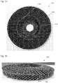
- the Figures 1a and 1b show a flap disc 101 according to the prior art, the Figure 1a a top view and the Figure 1b shows a perspective view obliquely from above.
- the flap disc 101 comprises a carrier 102 on which grinding flaps 103 are arranged so as to overlap one another.
- the grinding flaps 103 have a rectangular shape. At the inner edge 130, the grinding lamellas are positioned most closely packed against one another, the packing density decreasing in the radial direction. As a result, the distance 114 between adjacent grinding flaps 103 decreases towards the outer edge. This creates gaps 131 between adjacent grinding lamellas 103. These gaps 131 have a disadvantageous effect on the service life of the flap disc 101, since the mobility of the grinding lamellae 103 in the grinding insert caused by the gaps 131 results in additional mechanical stress and vibration of the grinding lamellae 103 and further As a result, the abrasive lamellas 103 will wear out.
- the U.S. 2,907,147 discloses a flap disc according to the preamble of claim 1.
- the object of the present invention is to provide a flap disc which is improved compared to the prior art, in which the above-described problems have essentially been eliminated and which, in particular in the outer area, has no significant gaps between adjacent grinding lamellas.
- a further object of the invention is to provide a method for producing a flap disc improved in this way.
- the ratio of the length of the second trapezoidal side to the length of the first trapezoidal side is essentially equal to the ratio of the outer ring diameter to the inner ring diameter.
- Another advantage is that a greater amount of flap material can be used up due to wear and tear, since more flap material is available on the outer ring diameter.
- the ratio of the length of the second trapezoidal side to the length of the first trapezoidal side or the ratio of the outer ring diameter to the inner ring diameter is 1 1.2 and 2.5, preferably 1.5 and ⁇ 2.0.
- the grinding flap wheel By avoiding the formation of a gap, it is possible to design the grinding flap wheel in such a way that the grinding flap wheel has a grinding surface formed from the overlapping grinding lamellas, which can be brought into contact with a workpiece to be machined, the grinding flap wheel has an axis of rotation, the grinding surface in Is essentially flat, and the axis of rotation is aligned essentially normal to the grinding surface. This optimizes the grinding performance of the flap disc.
- the flap disc according to the invention it is possible to arrange the grinding flaps in such a way that the distance between two adjacent grinding flaps on the inner ring diameter is essentially the same as the distance on the outer ring diameter. This also has an advantageous effect on the grinding properties of the flap disc.
- the abrasive lamellas each have a textile base on which abrasive grains are attached with the help of at least one binder, and / or that the carrier as a glass fiber reinforced plastic carrier, as a plastic carrier, as a natural fiber carrier or as Steel support is formed.
- the binder can be synthetic resins. Cotton, polyester or mixed textiles made from both fibers are suitable as a textile underlay. Before applying the abrasive grains (e.g. normal corundum or zirconium corundum with a grain size of 24-120 mesh, or also SiC), a thin bonding layer of resin (basic bond), e.g. phenolic resin, should be applied. After the abrasive grains have been applied and the same has been electrostatically aligned, a size binder, which, in addition to resin, for example, can also contain fillers, can then be applied. In the case of very high-quality sanding belts, provision can be made for an additional application of a binding layer with a high filler content, which is also referred to as top size. For curing, one or more thermal curing processes are carried out.
- abrasive grains e.g. normal corundum or zirconium corundum with a grain size of 24-120 mesh, or also SiC
- the glass fiber reinforced plastic carrier can be produced by building up layers and pressing glass fiber fabrics pre-impregnated with phenolic resin, which are cured in the oven. If the carrier is designed as a plastic carrier, then it is advisable to injection-mold the carrier from thermoplastic, in which case glass fiber reinforced polyamide or ABS can be used, for example. Special variants are natural fiber carriers that can be used as reinforcement, for example hemp. And finally, the carrier can also be designed as a steel carrier, which is preferably an extruded or stamped thin steel carrier.
- the essentially rotationally symmetrical carrier is provided in a first method step, an adhesive, preferably an adhesive, is applied to the carrier in a second method step between the inner ring diameter and the outer ring diameter, and in a third Method step the grinding flaps, each of which has the shape of a trapezoid with a first trapezoidal side and a second trapezoidal side parallel to it, the length of the first trapezoidal side being smaller than the length of the second trapezoidal side and the ratio of the length of the second trapezoidal side to the length of the first Trapezoidal side is essentially the same as the ratio of the outer ring diameter to the inner ring diameter, arranged on the carrier in such a way that the grinding lamellas overlap and the first trapezoidal side of the grinding lamellae each on the inner ring diameter u nd the second trapezoidal side of the grinding flaps is arranged on the outer ring diameter.
- the grinding lamellae are initially placed one after the other in the course of the third process step with a third trapezoidal side, which connects the first trapezoidal side and the second trapezoidal side, on the carrier, with two adjacent grinding lamellae having a predetermined set distance relative to one another, and the abrasive flaps are then tilted in the direction of the carrier.
- the tilting of the grinding lamellae is particularly preferred in two stages, the grinding lamellae being slightly tilted in a first stage to specify a pressing direction, and the grinding lamellae being pressed in a second stage in the pressing direction onto the circular ring of the carrier.
- the predetermined setting distance can be achieved, for example, by rotating the carrier.
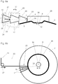
- the Figure 2 shows schematically a manufacturing method according to the prior art.
- One half of a carrier 102 is indicated in cross section, with the carrier has an inclined shape. Instead, a straight beam can also be used.
- the axis of rotation 113 is indicated with a dot-dash line.
- a grinding belt 119 is fed via a transport device 127, which comprises a transport roller which is mounted rotatably about an axis of rotation 129.
- a punching device 120 rectangular abrasive lamellas 103 are separated from this abrasive belt along separating lines 128 and placed on the carrier 102.
- a preferred embodiment of the method according to the invention provides that the grinding lamellae, which are arranged on the carrier in the course of the third method step, are separated from a serrated grinding belt, preferably by means of a punching device, wherein the serrated shape results from a sequential arrangement of the trapezoidal shape of the grinding flaps, preferably wherein the grinding flaps are separated from the grinding belt on the first trapezoidal side or on the second trapezoidal side.
- the flap disc has an axis of rotation and the serrated grinding belt in a feed direction in the direction of the Carrier is advanced, the direction of advance includes an angle to the axis of rotation, and the angle is selected such that a third trapezoidal side of the grinding flaps, which connects the first trapezoidal side and the second trapezoidal side, is aligned essentially parallel to a setting surface of the carrier.
- the angle can be changed in order to be able to process different trapezoidal shapes and / or that the angle is essentially 90 °.
- a stop ring can be used which is positioned on the carrier and against which the end of the serrated abrasive belt strikes, and / or a feed device is used which advances the serrated abrasive belt by the respective feed path.
- the serrated sanding belt can be separated from a sanding roller, the sanding roller having a width which corresponds to a multiple of the maximum width of the serrated sanding belt, preferably wherein at least two serrated sanding belts are separated from the sanding roller and the at least two serrated sanding belts are rotated 180 ° to each other are.
- the material of the grinding roller can be used almost without waste.
- FIGS. 3a, 3b and 3c show preferred embodiments of a flap disc according to the invention, only two grinding flaps 3 being shown.
- the flap disc has an essentially rotationally symmetrical carrier 2 and abrasive flaps 3, which are arranged on the carrier 2 so as to overlap one another.
- the grinding lamellae 3 each have the shape of a trapezoid with a first trapezoidal side 4 and a second trapezoidal side 5 parallel thereto, the length 6 of the first trapezoidal side 4 being smaller than the length 7 of the second trapezoidal side 5.
- the two trapezoidal sides 4 and 5 are connected to one another by two further trapezoidal sides 17 and 31.
- the carrier 2 has a circular ring 9 with an inner ring diameter 10 and an outer ring diameter 11.
- the grinding flaps 3 are arranged on the circular ring 9, the first trapezoidal side 4 of the grinding flaps 3 being arranged on the inner ring diameter 10 and the second trapezoidal side 5 of the grinding flaps 3 being arranged on the outer ring diameter 11.
- the grinding lamellae 3 can protrude somewhat beyond the circular ring 9 or the carrier 2.
- the carrier 2 further comprises a central bore 8, through the center 30 of which the axis of rotation of the flap disc runs.
- the hole 8 is used to connect the flap disc to a rotary drive of an angle grinder.
- the exemplary embodiments differ in that the grinding flaps 3 in the case of Figure 3a generally have the shape of a trapezoid, in the case of Figure 3b have the special shape of an isosceles trapezoid and in the case of the Figure 3c the special shape of a right-angled trapezoid exhibit.
- the trapezoidal shape is not important. It is essential that the ratio of the length 7 of the second trapezoidal side 5 to the length 6 of the first trapezoidal side 4 is essentially equal to the ratio of the outer ring diameter 11 to the inner ring diameter 10.
- the ratio of the length 7 of the second trapezoidal side 5 to the length 6 of the first trapezoidal side 4 or the ratio of the outer ring diameter 11 to the inner ring diameter 10 is 1.5 and 2.0.
- FIGS. 4a and 4b show a further embodiment of the flap disc 1 according to the invention.
- the grinding surface 12 formed from the overlapping grinding lamellas 3, which can be brought into contact with a workpiece to be processed is essentially flat, and the axis of rotation 13 is oriented essentially normal to the grinding surface 12.
- the distance between two adjacent grinding flaps 3 on the outer ring diameter 11 is provided with the reference symbol 14. This distance is essentially equal to the distance between two adjacent grinding lamellae 3 on the inner ring diameter 10.
- the abrasive lamellas 3 each have a textile base 15 to which abrasive grains 16 are attached with the aid of at least one binding agent.
- the Figures 5a and 5b show a first preferred embodiment of the method according to the invention for producing a flap disc.
- the essentially rotationally symmetrical carrier 2 is provided in a first method step.
- it is an inclined carrier 2, in which the outer area of the carrier runs inclined with respect to the axis of rotation 13 and slopes down.
- a carrier 2 that is straight can also be used just as well.
- the feed device 27 and punching device 20 described below can be rotated relative to the carrier 2. This is indicated by the arrow 32.
- the rotation of the feed device 27 and the punching device 20 relative to the carrier 2 also serves to be able to set grinding flaps with different trapezoidal angles.
- the serrated sanding belt 19 is advanced in a feed direction 34 in the direction of the carrier 2, the feed direction 34 enclosing an angle 35 to the axis of rotation 13, and the angle 35 can be selected such that the third trapezoidal side 17 of the grinding flaps 3, which the connects the first trapezoidal side 4 and the second trapezoidal side 5, is oriented essentially parallel to a setting surface 36 of the carrier 2.
- the grinding flaps 3 are arranged on the carrier 2 in such a way that the grinding flaps 3 overlap each other and the first trapezoidal side 4 of the grinding flaps 3 each on the inner ring diameter 10 and the second trapezoidal side 5 of the grinding flaps 3 each on the outer ring diameter 11 is arranged.
- the grinding lamellae 3 are first placed one after the other with a third trapezoidal side 17, which connects the first trapezoidal side 4 and the second trapezoidal side 5, on the carrier 2, with two adjacent grinding lamellas 3 having a predetermined set distance 18 relative to one another.
- the grinding lamellae 3 which are arranged on the carrier 2 in the course of the third process step, are separated from a serrated grinding belt 19 by means of a punching device 20, the serrated shape of the grinding belt 19 resulting from a sequential arrangement of the trapezoidal shape of the grinding lamellae 3.
- the grinding lamellae 3 are cut off on the second side 5 of the trapezoid.
- an end 23 of the serrated abrasive belt 19 is positioned on the carrier 2 in a first substep.
- a grinding lamella 3 is separated from the serrated grinding belt 19, specifically along a separating line 28 which corresponds to part of the second trapezoidal side 5 of the grinding lamella 3 to be separated.
- the carrier 2 and the serrated grinding belt 19 are rotated relative to one another by a predetermined angle 24 to achieve the predetermined set distance 18 between two adjacent grinding lamellae 3 (cf. Figure 5b ).
- the three partial steps are repeated until the carrier 2 is equipped with the predetermined number of grinding lamellae 3.
- the loading time for all grinding lamellas 3 is less than 3 seconds.
- the grinding lamellae 3 are tilted in the direction of the carrier 2.
- the tilting of the grinding lamellae 3 takes place in two stages, the grinding lamellae 3 being slightly tilted in a first stage to specify a pressing direction, and the grinding lamellae 3 being pressed onto the circular ring 9 of the carrier 2 in a second stage in the pressing direction.
- a pressure bell for example, is used for this purpose.
- a feed device 27 in the form of one or more transport rollers, which can be rotated about an axis of rotation 29, is used. This advancing device 27 advances the serrated grinding belt 19 by the advancing path 25.
- a stop ring 26 can also be used which is positioned on the carrier 2 and against which the end 23 of the serrated abrasive belt 19 strikes. This embodiment of the method according to the invention is shown in Figures 6a and 6b shown.
- the serrated abrasive belt 19 is advanced essentially transversely to the axis of rotation 13 in the direction of the carrier 2.
- the serrated abrasive belt 19 it can, as in Figure 7 It can be provided that the serrated abrasive belt 19 is cut out of a grinding roller 21, the grinding roller 21 having a width 22 which is a multiple of the maximum width 7 (compare for example Figure 5a ) corresponds, with two adjacent serrated grinding belts 19 being rotated by 180 ° relative to one another. In this way, the grinding belts 19 can be separated from the grinding roller 21 with almost no waste. Only the outer edge strips 33 have to be disposed of as waste.
- ring-shaped knives with the desired serrated shape are preferably used.
- the strips can also be separated with the aid of laser radiation or the like.
- the individual strips are rolled up and can now be fed to the setting and punching process for the filling of a carrier body with grinding lamellas.
Claims (15)
- Meule en éventail (1) pour une meuleuse d'angle, comprenant un support (2) essentiellement à symétrie de rotation et des lamelles de meulage (3), lesquelles sont disposées en se chevauchant les unes les autres sur le support (2), dans laquelle les lamelles de meulage (3) présentent à chaque fois une forme de trapèze avec un premier côté de trapèze (4) et un deuxième côté de trapèze (5) lui étant parallèle, et dans laquelle la longueur (6) du premier côté de trapèze (4) est inférieure à la longueur (7) du deuxième côté de trapèze (5), le support (2) présente un anneau circulaire (9) avec un diamètre annulaire interne (10) et un diamètre annulaire externe (11), les lamelles de meulage (3) sont disposées sur l'anneau circulaire (9), dans laquelle le premier côté de trapèze (4) des lamelles de meulage (3) est disposé à chaque fois sur le diamètre annulaire interne (10) et le deuxième côté de trapèze (5) des lamelles de meulage (3) à chaque fois sur le diamètre annulaire externe (11), caractérisée en ce que le rapport de la longueur (7) du deuxième côté de trapèze (5) par rapport à la longueur (6) du premier côté de trapèze (4) est essentiellement égal au rapport du diamètre annulaire externe (11) par rapport au diamètre annulaire interne (10).
- Meule en éventail (1) selon la revendication 1, dans laquelle le rapport de la longueur (7) du deuxième côté de trapèze (5) par rapport à la longueur (6) du premier côté de trapèze (4) ou le rapport du diamètre annulaire externe (11) par rapport au diamètre annulaire interne (10) est ≥ 1,2 et ≤ 2,5, de préférence ≥ 1,5 et ≤ 2,0.
- Meule en éventail (1) selon la revendication 1 ou 2, dans laquelle la meule en éventail (1) présente une surface de meulage (12) formée des lamelles de meulage (3) se chevauchant, laquelle peut être mise en contact avec une pièce à usiner, la meule en éventail (1) présente un axe de rotation (13), la surface de meulage (12) est conçue essentiellement plane, et l'axe de rotation (13) est orienté essentiellement perpendiculaire à la surface de meulage (12).
- Meule en éventail (1) selon l'une des revendications 1 à 3, dans laquelle l'écart entre deux lamelles de meulage contiguës (3) est sur le diamètre annulaire interne (10) essentiellement égal à l'écart (14) sur le diamètre annulaire externe (11).
- Meule en éventail (1) selon l'une des revendications 1 à 4, dans laquelle les lamelles de meulage (3) présentent à chaque fois un support textile (15) sur lequel sont attachés des grains abrasifs (16) à l'aide d'au moins un agent liant.
- Meule en éventail (1) selon l'une des revendications 1 à 5, dans laquelle le support (2) est conçu comme un support en matière synthétique renforcée par des fibres de verre, comme un support en matière plastique, comme un support en fibres naturelles ou comme un support en acier.
- Procédé de fabrication d'une meule en éventail (1) selon l'une des revendications précédentes, dans lequel dans une première étape du procédé est fabriqué le support essentiellement à symétrie de rotation (2), dans une deuxième étape du procédé est appliqué sur le support (2), entre le diamètre annulaire interne (10) et le diamètre annulaire externe (11), un agent adhésif, de préférence une colle, et dans une troisième étape du procédé les lamelles de meulage (3), lesquelles présentent à chaque fois une forme de trapèze avec un premier côté de trapèze (4) et un deuxième côté de trapèze (5) lui étant parallèle, dans lequel la longueur (6) du premier côté de trapèze (4) est inférieure à la longueur (7) du deuxième côté de trapèze (5) et le rapport de la longueur (7) du deuxième côté de trapèze (5) par rapport à la longueur (6) du premier côté de trapèze (4) est essentiellement égale au rapport du diamètre annulaire externe (11) par rapport au diamètre annulaire interne (10), sont disposées sur le support (2) de manière telle que les lamelles de meulage (3) se chevauchent les unes les autres et le premier côté de trapèze (4) des lamelles de meulage (3) est disposé à chaque fois sur le diamètre annulaire interne (10) et le deuxième côté de trapèze (5) des lamelles de meulage (3) est disposé à chaque fois sur le diamètre annulaire externe (11).
- Procédé selon la revendication 7, dans lequel les lamelles de meulage (3) à la suite de la troisième étape du procédé sont d'abord placées sur le support (2) les unes après les autres avec un troisième côté de trapèze (17), lequel relie le premier côté de trapèze (4) et le deuxième côté de trapèze (5), dans lequel deux lamelles de meulage contiguës (3) présentent un écart de positionnement prédéterminé (18) l'une par rapport à l'autre, et les lamelles de meulage (3) sont ensuite inclinées dans le sens du support (2).
- Procédé selon la revendication 8, dans lequel l'inclinaison des lamelles de meulage (3) se fait en deux étapes, dans lequel les lamelles de meulage (3), dans une première étape, sont légèrement inclinées pour prédéfinir un sens de pression, et dans lequel les lamelles de meulage (3), dans une deuxième étape, sont pressées dans un sens de pression sur l'anneau circulaire (9) du support (2).
- Procédé selon l'une des revendications 7 à 9, dans lequel les lamelles de meulage (3) qui au cours de la troisième étape du procédé sont disposées sur le support (2), sont séparées d'une bande abrasive dentelée (19), de préférence au moyen d'un dispositif de découpage (20), dans lequel la forme dentelée résulte d'un agencement séquentiel de la forme de trapèze des lamelles de meulage (3), de préférence dans lequel les lamelles de meulage (3) sont séparées de la bande abrasive (19) sur le premier côté de trapèze (4) ou sur le deuxième côté de trapèze (5).
- Procédé selon la revendication 10, dans lequel la bande abrasive dentelée (19) est détachée d'un rouleau abrasif (21), dans lequel le rouleau abrasif (21) présente une largeur (22), laquelle correspond à un multiple de la largeur maximale (7) de la bande abrasive dentelée (19), de préférence, dans lequel au moins deux bandes abrasives dentelées (19) sont détachées du rouleau abrasif (21) et les au moins deux bandes abrasives dentelées (19) sont tournées à 180° les unes vers les autres.
- Procédé selon la revendication 10 ou 11, dans lequel dans une première étape partielle, une extrémité (23) de la bande abrasive dentelée (19) est positionnée sur le support (2), dans une deuxième étape partielle, une lamelle de meulage (3) est séparée de la bande abrasive dentelée (19), dans une troisième étape partielle, le support (2) et la bande abrasive dentelée (19) sont tordus l'un par rapport à l'autre selon un angle prédéterminé (24) pour atteindre un écart de positionnement prédéterminé (18) de deux lamelles de meulage contiguës (3), et les trois étapes partielles sont répétées jusqu'à ce que le support (2) soit garni d'un nombre prédéterminé de lamelles de meulage (3), le temps total de garnissage s'élevant, de préférence, à moins de 3 secondes.
- Procédé selon l'une des revendications 10 à 12, dans lequel la meule en éventail (1) présente un axe de rotation (13) et la bande adhésive dentelée (19) est avancée dans un sens d'avancement (34) dans le sens du support (2), le sens d'avancement (34) inclut un angle (35) par rapport à l'axe de rotation (13), et l'angle (35) est choisi de manière telle qu'un troisième côté de trapèze (17) des lamelles de meulage (3), lequel relie le premier côté de trapèze (4) et le deuxième côté de trapèze (5), est orienté essentiellement en parallèle d'une surface de pose (36) du support (2).
- Procédé selon la revendication 13, dans lequel l'angle (35) est modifiable, et / ou est essentiellement de 90°.
- Procédé selon la revendication 13 ou 14, dans lequel pour obtenir un trajet d'avancement prédéterminé (25) est utilisée une bague de butée (26), laquelle est positionnée sur le support (2) et sur laquelle bute l'extrémité (23) de la bande adhésive dentelée (19), et / ou un dispositif d'avancement (27) est utilisé, lequel pousse à chaque fois la bande abrasive dentelée (19) autour du trajet d'avancement (25).
Priority Applications (1)
| Application Number | Priority Date | Filing Date | Title |
|---|---|---|---|
| PL18742902T PL3651936T3 (pl) | 2017-07-11 | 2018-07-05 | Wachlarzowa tarcza szlifierska do szlifierki kątowej |
Applications Claiming Priority (2)
| Application Number | Priority Date | Filing Date | Title |
|---|---|---|---|
| ATA50573/2017A AT520116B1 (de) | 2017-07-11 | 2017-07-11 | Fächerschleifscheibe für einen Winkelschleifer |
| PCT/AT2018/060135 WO2019010508A1 (fr) | 2017-07-11 | 2018-07-05 | Meule en éventail pour meuleuse d'angle |
Publications (2)
| Publication Number | Publication Date |
|---|---|
| EP3651936A1 EP3651936A1 (fr) | 2020-05-20 |
| EP3651936B1 true EP3651936B1 (fr) | 2020-11-04 |
Family
ID=62975775
Family Applications (1)
| Application Number | Title | Priority Date | Filing Date |
|---|---|---|---|
| EP18742902.2A Active EP3651936B1 (fr) | 2017-07-11 | 2018-07-05 | Meule en éventail pour meuleuse d'angle |
Country Status (5)
| Country | Link |
|---|---|
| EP (1) | EP3651936B1 (fr) |
| AT (1) | AT520116B1 (fr) |
| ES (1) | ES2849563T3 (fr) |
| PL (1) | PL3651936T3 (fr) |
| WO (1) | WO2019010508A1 (fr) |
Families Citing this family (1)
| Publication number | Priority date | Publication date | Assignee | Title |
|---|---|---|---|---|
| EP4017683A1 (fr) * | 2019-08-19 | 2022-06-29 | Diamabrush LLC | Appareil de polissage de sol |
Family Cites Families (4)
| Publication number | Priority date | Publication date | Assignee | Title |
|---|---|---|---|---|
| US2907147A (en) * | 1957-12-23 | 1959-10-06 | F L & J C Codman Company | Radial face rotary buffing element |
| DE29510727U1 (de) * | 1995-01-24 | 1995-08-31 | Lukas Erzett Schleif Fraes | Werkzeug, insbesondere Schleif- oder Polierteller |
| DE202010008898U1 (de) * | 2010-10-26 | 2010-12-30 | Lukas-Erzett Vereinigte Schleif- Und Fräswerkzeugfabriken Gmbh & Co. Kg | Schleiflamelle zum Anordnen auf einer um eine Drehachse rotierend antreibbaren Schleifscheibe |
| DE102011100792A1 (de) * | 2011-05-06 | 2012-11-08 | Rhodius Schleifwerkzeuge Gmbh & Co. Kg | Flexible Schleifscheibe |
-
2017
- 2017-07-11 AT ATA50573/2017A patent/AT520116B1/de active
-
2018
- 2018-07-05 WO PCT/AT2018/060135 patent/WO2019010508A1/fr unknown
- 2018-07-05 PL PL18742902T patent/PL3651936T3/pl unknown
- 2018-07-05 ES ES18742902T patent/ES2849563T3/es active Active
- 2018-07-05 EP EP18742902.2A patent/EP3651936B1/fr active Active
Non-Patent Citations (1)
| Title |
|---|
| None * |
Also Published As
| Publication number | Publication date |
|---|---|
| PL3651936T3 (pl) | 2021-06-14 |
| AT520116A1 (de) | 2019-01-15 |
| EP3651936A1 (fr) | 2020-05-20 |
| ES2849563T3 (es) | 2021-08-19 |
| WO2019010508A1 (fr) | 2019-01-17 |
| AT520116B1 (de) | 2022-10-15 |
Similar Documents
| Publication | Publication Date | Title |
|---|---|---|
| DE102014004994B3 (de) | Chopperscheibe sowie Vorrichtung und Verfahren zu deren Herstellung | |
| DE3700250C2 (fr) | ||
| DE4300057B4 (de) | Mit einem Schleifmittel beschichtetes Erzeugnis und Verfahren zu dessen Herstellung | |
| EP2087971A2 (fr) | Dispositif de coupe | |
| EP3315008A1 (fr) | Rouleau de transport et rouleau conditionneur pour une récolteuse | |
| DE602004008623T2 (de) | Stanzvorrichtungsgummituch | |
| CH359376A (de) | Schleifvorrichtung, Verwendung der Schleifvorrichtung und Verfahren zu ihrer Herstellung | |
| EP3651936B1 (fr) | Meule en éventail pour meuleuse d'angle | |
| DE60104393T2 (de) | Schleifscheibe und herstellungsverfahren einer solchen scheibe | |
| DE3236045C2 (de) | Steinbearbeitungswerkzeug | |
| DE3927106C2 (fr) | ||
| WO2018015162A1 (fr) | Produit en lamibois et son procédé de production | |
| EP3181293B1 (fr) | Outil de finition à capacité de coupe variable localement | |
| WO2007107129A1 (fr) | FRAISEUSE cylindrique A LAME DE COUPE DE FORME HELICOIDALE | |
| DE19511004C1 (de) | Werkzeug mit einem Schleif- oder Polierbelag | |
| DE69727890T2 (de) | Verfahren und Maschine zur Herstellung eines scheibenförmigen Elementes aus einem kontinuierlichen Faden sowie ein hergestelltes scheibenförmiges Element | |
| EP1488128B1 (fr) | Support de garniture de friction, en particulier sabot de frein, pour frein de stationnement ou frein a tambour, procede de production correspondant et dispositif pour mettre en oeuvre ce procede | |
| WO2009068205A1 (fr) | Dispositif de coupe et procédé d'utilisation d'un dispositif de coupe | |
| EP2193882A2 (fr) | Disque à diamant incliné | |
| EP1138440A2 (fr) | Outil de meulage et son procédé de fabrication | |
| EP0806260B1 (fr) | Procédé et dispositif pour retirer le revêtement élastomère usagé d'un cylindre | |
| DE102009060568A1 (de) | Schneidvorrichtung und Schneidmesser zum Schneiden von stabförmigen Produkten der Tabak verarbeitenden Industrie | |
| DE102005031198A1 (de) | Scheifen eines Schneidmessers der tabakverarbeitenden Industrie | |
| DE10242853B4 (de) | Reibbelagträger, insbesondere Bremsschuh, für Feststell- oder Trommelbremsen sowie ein diesbezügliches Herstellungsverfahren sowie eine Vorrichtung zur Durchführung des Verfahrens | |
| DE4338492A1 (de) | Trenn-Schleifscheibe für stationäre Schleifmaschinenund deren Verwendung |
Legal Events
| Date | Code | Title | Description |
|---|---|---|---|
| STAA | Information on the status of an ep patent application or granted ep patent |
Free format text: STATUS: UNKNOWN |
|
| STAA | Information on the status of an ep patent application or granted ep patent |
Free format text: STATUS: THE INTERNATIONAL PUBLICATION HAS BEEN MADE |
|
| PUAI | Public reference made under article 153(3) epc to a published international application that has entered the european phase |
Free format text: ORIGINAL CODE: 0009012 |
|
| STAA | Information on the status of an ep patent application or granted ep patent |
Free format text: STATUS: REQUEST FOR EXAMINATION WAS MADE |
|
| 17P | Request for examination filed |
Effective date: 20191210 |
|
| AK | Designated contracting states |
Kind code of ref document: A1 Designated state(s): AL AT BE BG CH CY CZ DE DK EE ES FI FR GB GR HR HU IE IS IT LI LT LU LV MC MK MT NL NO PL PT RO RS SE SI SK SM TR |
|
| AX | Request for extension of the european patent |
Extension state: BA ME |
|
| GRAP | Despatch of communication of intention to grant a patent |
Free format text: ORIGINAL CODE: EPIDOSNIGR1 |
|
| STAA | Information on the status of an ep patent application or granted ep patent |
Free format text: STATUS: GRANT OF PATENT IS INTENDED |
|
| DAV | Request for validation of the european patent (deleted) | ||
| DAX | Request for extension of the european patent (deleted) | ||
| INTG | Intention to grant announced |
Effective date: 20200724 |
|
| GRAS | Grant fee paid |
Free format text: ORIGINAL CODE: EPIDOSNIGR3 |
|
| GRAA | (expected) grant |
Free format text: ORIGINAL CODE: 0009210 |
|
| STAA | Information on the status of an ep patent application or granted ep patent |
Free format text: STATUS: THE PATENT HAS BEEN GRANTED |
|
| AK | Designated contracting states |
Kind code of ref document: B1 Designated state(s): AL AT BE BG CH CY CZ DE DK EE ES FI FR GB GR HR HU IE IS IT LI LT LU LV MC MK MT NL NO PL PT RO RS SE SI SK SM TR |
|
| REG | Reference to a national code |
Ref country code: GB Ref legal event code: FG4D Free format text: NOT ENGLISH |
|
| REG | Reference to a national code |
Ref country code: CH Ref legal event code: EP |
|
| REG | Reference to a national code |
Ref country code: AT Ref legal event code: REF Ref document number: 1330189 Country of ref document: AT Kind code of ref document: T Effective date: 20201115 |
|
| REG | Reference to a national code |
Ref country code: DE Ref legal event code: R096 Ref document number: 502018002938 Country of ref document: DE |
|
| REG | Reference to a national code |
Ref country code: IE Ref legal event code: FG4D Free format text: LANGUAGE OF EP DOCUMENT: GERMAN |
|
| REG | Reference to a national code |
Ref country code: CH Ref legal event code: NV Representative=s name: ISLER AND PEDRAZZINI AG, CH |
|
| REG | Reference to a national code |
Ref country code: NL Ref legal event code: FP |
|
| PG25 | Lapsed in a contracting state [announced via postgrant information from national office to epo] |
Ref country code: NO Free format text: LAPSE BECAUSE OF FAILURE TO SUBMIT A TRANSLATION OF THE DESCRIPTION OR TO PAY THE FEE WITHIN THE PRESCRIBED TIME-LIMIT Effective date: 20210204 Ref country code: GR Free format text: LAPSE BECAUSE OF FAILURE TO SUBMIT A TRANSLATION OF THE DESCRIPTION OR TO PAY THE FEE WITHIN THE PRESCRIBED TIME-LIMIT Effective date: 20210205 Ref country code: FI Free format text: LAPSE BECAUSE OF FAILURE TO SUBMIT A TRANSLATION OF THE DESCRIPTION OR TO PAY THE FEE WITHIN THE PRESCRIBED TIME-LIMIT Effective date: 20201104 Ref country code: RS Free format text: LAPSE BECAUSE OF FAILURE TO SUBMIT A TRANSLATION OF THE DESCRIPTION OR TO PAY THE FEE WITHIN THE PRESCRIBED TIME-LIMIT Effective date: 20201104 Ref country code: PT Free format text: LAPSE BECAUSE OF FAILURE TO SUBMIT A TRANSLATION OF THE DESCRIPTION OR TO PAY THE FEE WITHIN THE PRESCRIBED TIME-LIMIT Effective date: 20210304 |
|
| PG25 | Lapsed in a contracting state [announced via postgrant information from national office to epo] |
Ref country code: BG Free format text: LAPSE BECAUSE OF FAILURE TO SUBMIT A TRANSLATION OF THE DESCRIPTION OR TO PAY THE FEE WITHIN THE PRESCRIBED TIME-LIMIT Effective date: 20210204 Ref country code: IS Free format text: LAPSE BECAUSE OF FAILURE TO SUBMIT A TRANSLATION OF THE DESCRIPTION OR TO PAY THE FEE WITHIN THE PRESCRIBED TIME-LIMIT Effective date: 20210304 Ref country code: LV Free format text: LAPSE BECAUSE OF FAILURE TO SUBMIT A TRANSLATION OF THE DESCRIPTION OR TO PAY THE FEE WITHIN THE PRESCRIBED TIME-LIMIT Effective date: 20201104 Ref country code: SE Free format text: LAPSE BECAUSE OF FAILURE TO SUBMIT A TRANSLATION OF THE DESCRIPTION OR TO PAY THE FEE WITHIN THE PRESCRIBED TIME-LIMIT Effective date: 20201104 |
|
| REG | Reference to a national code |
Ref country code: LT Ref legal event code: MG9D |
|
| PG25 | Lapsed in a contracting state [announced via postgrant information from national office to epo] |
Ref country code: HR Free format text: LAPSE BECAUSE OF FAILURE TO SUBMIT A TRANSLATION OF THE DESCRIPTION OR TO PAY THE FEE WITHIN THE PRESCRIBED TIME-LIMIT Effective date: 20201104 |
|
| PG25 | Lapsed in a contracting state [announced via postgrant information from national office to epo] |
Ref country code: EE Free format text: LAPSE BECAUSE OF FAILURE TO SUBMIT A TRANSLATION OF THE DESCRIPTION OR TO PAY THE FEE WITHIN THE PRESCRIBED TIME-LIMIT Effective date: 20201104 Ref country code: SK Free format text: LAPSE BECAUSE OF FAILURE TO SUBMIT A TRANSLATION OF THE DESCRIPTION OR TO PAY THE FEE WITHIN THE PRESCRIBED TIME-LIMIT Effective date: 20201104 Ref country code: SM Free format text: LAPSE BECAUSE OF FAILURE TO SUBMIT A TRANSLATION OF THE DESCRIPTION OR TO PAY THE FEE WITHIN THE PRESCRIBED TIME-LIMIT Effective date: 20201104 Ref country code: RO Free format text: LAPSE BECAUSE OF FAILURE TO SUBMIT A TRANSLATION OF THE DESCRIPTION OR TO PAY THE FEE WITHIN THE PRESCRIBED TIME-LIMIT Effective date: 20201104 Ref country code: LT Free format text: LAPSE BECAUSE OF FAILURE TO SUBMIT A TRANSLATION OF THE DESCRIPTION OR TO PAY THE FEE WITHIN THE PRESCRIBED TIME-LIMIT Effective date: 20201104 |
|
| REG | Reference to a national code |
Ref country code: DE Ref legal event code: R097 Ref document number: 502018002938 Country of ref document: DE |
|
| REG | Reference to a national code |
Ref country code: ES Ref legal event code: FG2A Ref document number: 2849563 Country of ref document: ES Kind code of ref document: T3 Effective date: 20210819 |
|
| PG25 | Lapsed in a contracting state [announced via postgrant information from national office to epo] |
Ref country code: DK Free format text: LAPSE BECAUSE OF FAILURE TO SUBMIT A TRANSLATION OF THE DESCRIPTION OR TO PAY THE FEE WITHIN THE PRESCRIBED TIME-LIMIT Effective date: 20201104 |
|
| PLBE | No opposition filed within time limit |
Free format text: ORIGINAL CODE: 0009261 |
|
| STAA | Information on the status of an ep patent application or granted ep patent |
Free format text: STATUS: NO OPPOSITION FILED WITHIN TIME LIMIT |
|
| 26N | No opposition filed |
Effective date: 20210805 |
|
| PG25 | Lapsed in a contracting state [announced via postgrant information from national office to epo] |
Ref country code: AL Free format text: LAPSE BECAUSE OF FAILURE TO SUBMIT A TRANSLATION OF THE DESCRIPTION OR TO PAY THE FEE WITHIN THE PRESCRIBED TIME-LIMIT Effective date: 20201104 |
|
| PG25 | Lapsed in a contracting state [announced via postgrant information from national office to epo] |
Ref country code: SI Free format text: LAPSE BECAUSE OF FAILURE TO SUBMIT A TRANSLATION OF THE DESCRIPTION OR TO PAY THE FEE WITHIN THE PRESCRIBED TIME-LIMIT Effective date: 20201104 |
|
| PG25 | Lapsed in a contracting state [announced via postgrant information from national office to epo] |
Ref country code: MC Free format text: LAPSE BECAUSE OF FAILURE TO SUBMIT A TRANSLATION OF THE DESCRIPTION OR TO PAY THE FEE WITHIN THE PRESCRIBED TIME-LIMIT Effective date: 20201104 |
|
| REG | Reference to a national code |
Ref country code: BE Ref legal event code: MM Effective date: 20210731 |
|
| PG25 | Lapsed in a contracting state [announced via postgrant information from national office to epo] |
Ref country code: IS Free format text: LAPSE BECAUSE OF FAILURE TO SUBMIT A TRANSLATION OF THE DESCRIPTION OR TO PAY THE FEE WITHIN THE PRESCRIBED TIME-LIMIT Effective date: 20210304 Ref country code: LU Free format text: LAPSE BECAUSE OF NON-PAYMENT OF DUE FEES Effective date: 20210705 |
|
| PG25 | Lapsed in a contracting state [announced via postgrant information from national office to epo] |
Ref country code: IE Free format text: LAPSE BECAUSE OF NON-PAYMENT OF DUE FEES Effective date: 20210705 Ref country code: BE Free format text: LAPSE BECAUSE OF NON-PAYMENT OF DUE FEES Effective date: 20210731 |
|
| PG25 | Lapsed in a contracting state [announced via postgrant information from national office to epo] |
Ref country code: CY Free format text: LAPSE BECAUSE OF FAILURE TO SUBMIT A TRANSLATION OF THE DESCRIPTION OR TO PAY THE FEE WITHIN THE PRESCRIBED TIME-LIMIT Effective date: 20201104 |
|
| PG25 | Lapsed in a contracting state [announced via postgrant information from national office to epo] |
Ref country code: HU Free format text: LAPSE BECAUSE OF FAILURE TO SUBMIT A TRANSLATION OF THE DESCRIPTION OR TO PAY THE FEE WITHIN THE PRESCRIBED TIME-LIMIT; INVALID AB INITIO Effective date: 20180705 |
|
| PGFP | Annual fee paid to national office [announced via postgrant information from national office to epo] |
Ref country code: CZ Payment date: 20230621 Year of fee payment: 6 |
|
| PGFP | Annual fee paid to national office [announced via postgrant information from national office to epo] |
Ref country code: TR Payment date: 20230622 Year of fee payment: 6 Ref country code: PL Payment date: 20230616 Year of fee payment: 6 Ref country code: NL Payment date: 20230725 Year of fee payment: 6 |
|
| PGFP | Annual fee paid to national office [announced via postgrant information from national office to epo] |
Ref country code: IT Payment date: 20230705 Year of fee payment: 6 Ref country code: GB Payment date: 20230718 Year of fee payment: 6 Ref country code: ES Payment date: 20230816 Year of fee payment: 6 Ref country code: CH Payment date: 20230801 Year of fee payment: 6 Ref country code: AT Payment date: 20230728 Year of fee payment: 6 |
|
| PGFP | Annual fee paid to national office [announced via postgrant information from national office to epo] |
Ref country code: FR Payment date: 20230728 Year of fee payment: 6 Ref country code: DE Payment date: 20230727 Year of fee payment: 6 |
|
| PG25 | Lapsed in a contracting state [announced via postgrant information from national office to epo] |
Ref country code: MK Free format text: LAPSE BECAUSE OF FAILURE TO SUBMIT A TRANSLATION OF THE DESCRIPTION OR TO PAY THE FEE WITHIN THE PRESCRIBED TIME-LIMIT Effective date: 20201104 |