EP3649863B1 - Benne élévatrice avec dispositif de sortie pour masses d'aliments compacts, en particulier de masses pour barres ou pâtes à biscuits - Google Patents
Benne élévatrice avec dispositif de sortie pour masses d'aliments compacts, en particulier de masses pour barres ou pâtes à biscuits Download PDFInfo
- Publication number
- EP3649863B1 EP3649863B1 EP18205172.2A EP18205172A EP3649863B1 EP 3649863 B1 EP3649863 B1 EP 3649863B1 EP 18205172 A EP18205172 A EP 18205172A EP 3649863 B1 EP3649863 B1 EP 3649863B1
- Authority
- EP
- European Patent Office
- Prior art keywords
- cutting tools
- lifting
- lifting tipper
- vat
- tipper
- Prior art date
- Legal status (The legal status is an assumption and is not a legal conclusion. Google has not performed a legal analysis and makes no representation as to the accuracy of the status listed.)
- Active
Links
Images


Classifications
-
- A—HUMAN NECESSITIES
- A21—BAKING; EDIBLE DOUGHS
- A21C—MACHINES OR EQUIPMENT FOR MAKING OR PROCESSING DOUGHS; HANDLING BAKED ARTICLES MADE FROM DOUGH
- A21C1/00—Mixing or kneading machines for the preparation of dough
- A21C1/14—Structural elements of mixing or kneading machines; Parts; Accessories
- A21C1/144—Discharge mechanisms
- A21C1/1445—Discharge mechanisms using tiltable receptacles; Tilting mechanisms therefor
-
- B—PERFORMING OPERATIONS; TRANSPORTING
- B01—PHYSICAL OR CHEMICAL PROCESSES OR APPARATUS IN GENERAL
- B01F—MIXING, e.g. DISSOLVING, EMULSIFYING OR DISPERSING
- B01F35/00—Accessories for mixers; Auxiliary operations or auxiliary devices; Parts or details of general application
- B01F35/75—Discharge mechanisms
- B01F35/754—Discharge mechanisms characterised by the means for discharging the components from the mixer
- B01F35/75455—Discharge mechanisms characterised by the means for discharging the components from the mixer using a rotary discharge means, e.g. a screw beneath the receptacle
-
- B—PERFORMING OPERATIONS; TRANSPORTING
- B01—PHYSICAL OR CHEMICAL PROCESSES OR APPARATUS IN GENERAL
- B01F—MIXING, e.g. DISSOLVING, EMULSIFYING OR DISPERSING
- B01F35/00—Accessories for mixers; Auxiliary operations or auxiliary devices; Parts or details of general application
- B01F35/75—Discharge mechanisms
- B01F35/754—Discharge mechanisms characterised by the means for discharging the components from the mixer
- B01F35/7548—Discharge mechanisms characterised by the means for discharging the components from the mixer using tilting or pivoting means for emptying the mixing receptacle
-
- B—PERFORMING OPERATIONS; TRANSPORTING
- B01—PHYSICAL OR CHEMICAL PROCESSES OR APPARATUS IN GENERAL
- B01F—MIXING, e.g. DISSOLVING, EMULSIFYING OR DISPERSING
- B01F2101/00—Mixing characterised by the nature of the mixed materials or by the application field
- B01F2101/06—Mixing of food ingredients
- B01F2101/08—Mixing of dough
Definitions
- the present invention relates to a lifting tipper with a discharge device for discharging a compact food mass from a kneading tub with the features of the preamble of claim 1 and a method for discharging a compact food mass from a kneading tub arranged in a lifting tipper.
- Products such as biscuits, gingerbread and bars, in particular protein bars, chocolate bars, muesli, fruit and cereal bars and the like have a highly viscous food mass, which entails special processing requirements.
- Mixing and kneading machines for such highly viscous food masses mainly consist of a mobile vat of different sizes for masses from 120 to 1000 kg, into which a motor-driven mixing and kneading tool for carrying out the mixing and kneading process protrudes.
- the tool is extended and the vat is driven to a processing plant.
- the tub is picked up by a lifting platform of the lifting tipper, brought to the height corresponding to the size of the lifting tipper and tilted by more than 90°, so that the mass in the vat falls into the input station of a processing device arranged below, which, for example, can be designed as a funnel.
- Such a lifting tipper is, for example, from the DE 19 40 501 U1 and the DE 42 09 689 C2 out.
- the disclosure document U.S. 2010/0271900 A1 also discloses a lift truck with a mixing tool according to the preamble of claim 1.
- the processing device includes, for example, the rolling of the mass for layer-by-layer application on a conveyor belt, as is desired in the case of multi-layer products, in particular bars or biscuits. It is the object of the present invention to provide a compact lifting tipper with a discharge device for discharging a tough food mass from a kneading vat, which ensures safe and hygienic food mass guidance in fully automatic operation.
- Compact foodstuff masses are understood to mean extremely firm doughs or bar, bar or tablet masses which are highly viscous, block-forming and non-flowable.
- dried fruit bars especially date-based ones, protein-enriched sports bars, and hard cookie and gingerbread doughs have such properties.
- the cutting tools are adapted to sever, slice or peel a compact mass of food.
- the compact food mass can be processed by the cutting tools in such a way that it falls out of the vat in small portions and manual processing of the mass is no longer necessary.
- the at least two cutting tools each have at least one cutter head, with the cutter head having the cutting edges.
- the cutting tools preferably each have a rod, at the end of which the at least one cutter head is arranged.
- the rod is a shaft which can be driven, in particular by means of an electric motor. Provision can also be made for the tub to be rotatable.
- the discharge device advantageously has three cutting tools which are arranged at approximately the same distance from one another.
- the cutter heads each have a base plate on which the rod stands orthogonally and from which at least two cutters protrude like wings, the sides of which are at least partially designed as cutting edges.
- Four knives per knife head are preferably provided.
- the discharge device can have an additional retaining device that prevents pieces of dough or masses that are too large from falling out of the tub.
- a restraining device would have the advantage that the size of the discharged masses could be reliably defined.
- This retaining device can be, for example, a plate or a grid covering the opening of the vat. The plate or grid has defined openings that are only permeable for a certain size of dough, so that pieces that are too large cannot fall out of the tub.
- the lift truck can have one or two columns.
- a crossbeam is preferably provided in the upper part, on which at least one holding device of the discharge device is arranged, which carries the at least two cutting tools. It is advantageous if the at least one holding device protrudes perpendicularly from the crossbeam and the at least one holding device has a rotary joint so that one end of the at least one holding device can be pivoted by means of an electric motor, with the at least two cutting tools on the part of the at least a holding device are arranged.
- the discharge device with holding device can also be attached to a lifting platform of the lifting tipper.
- the holding device is preferably set up to pivot the cutting tools into a kneading tub rotatably mounted on a lifting platform of the lifting tipper.
- the introduction it is also conceivable for the introduction to take place linearly.
- the rods of the at least two cutting tools preferably extend perpendicularly from the associated holding device. However, an angle between, for example, 80 and 110 degrees is also conceivable.
- the lifting tipper can also have a stripping device.
- the vat is preferably tilted first and then the discharge device is moved into the vat.
- the retraction and retraction of the cutting tools is preferably a pivoting process in which the cutting tools are pivoted in and out, in particular fully automatically.
- This method allows, in a simple and efficient way, to adapt the size of a viscous mass discharged from a vat to the downstream processing devices.
- the relative movement can be produced by rotating the cutting tools and/or rotating the tub.
- the cutting tools are rigid and the modeling clay moves around the cutting tools with the rotating tub.
- the cutting tools or the cutter heads of the cutting tools are preferably designed in such a way that they hold back the large pieces during the tipping process.
- Pivoting of the cutting tools into the kneading tub is preferably load-controlled.
- video monitoring can also be provided, in which the sizes of the dough masses can be observed using image analysis and, if necessary, influenced the regulation of the discharge device is taken to avoid the discharge of too large pieces from the vat.
- the Figures 1 to 3 show a preferred embodiment of a discharge device 1, which is mounted on a lifting tipper 2.
- the processing of a highly viscous food dough is described below.
- the discharge device is also suitable for processing high-viscosity bar, stick or tablet masses, which is analogous to dough processing.
- FIG 1 a lifting tipper 2 of a dough processing plant is shown.
- a dough mixing and kneading machine (not shown) is connected upstream of the lifting tipper 2 in the production flow.
- This dough mixing and kneading machine includes a vat in which the dough is shaped by a motor-driven mixing and kneading tool. After completion of the kneading process, the vat is driven to the lifting tipper.
- FIG 1 Fig. 14 illustrates the lift-tilting operation of the lift-tipper. First, a tub 3 in the lift-tipper 2 is lifted and then tilted.
- Such lifting tippers 2 are known from the prior art in a large number.
- the base body of the lifting tipper 2 has a base plate 5 and two parallel columns 6, on the inside of which there are guideways or guide rails for a lift truck 7.
- the truck 7 overflows Rolling in guideways of the rails along a direction of travel.
- a lifting platform not shown, is arranged on the lift truck 7 and is pivotably mounted on the lift truck 7 by means of a pivot bearing.
- the tub 3 is placed on the lifting platform, which can thus be tilted via the pivot bearing.
- the tilting axis is arranged perpendicular to the direction of travel of the lift truck. The tilting can be up to 120°, in particular 135°.
- the tub 3 is rotatably mounted on the lifting platform.
- An electric motor drives the vat 3 via a gear, in particular a roller body gear, which can be in the form of a friction gear or toothed wheel gear, and the vat 3 rotates about an axis of rotation that coincides with the longitudinal axis of the vat.
- a gear in particular a roller body gear, which can be in the form of a friction gear or toothed wheel gear, and the vat 3 rotates about an axis of rotation that coincides with the longitudinal axis of the vat.
- an axis of rotation 8 is arranged between the two columns 6, on which two chain deflection wheels (not shown) are arranged, on which roller chains run.
- a drive motor (not shown) is arranged, which drives the two parallel roller chains on which the truck 7 is attached.
- the axis of rotation 8 on which the chain deflection wheels are arranged is covered by a crossbeam 9 which connects the two columns 6 to one another.
- the discharge device 1 is located on the crossbeam 9 and has two tubular holding devices 10, 11, each of which has a swivel joint 12 and on which drivable cutting tools 13 are held.
- the two holding devices of the discharge device 10 , 11 can each be pivoted about the rotary joint 12 by means of a linear drive 14 .
- the cutting tool 13 is arranged on the pivotable part of the holding device 10,11.
- the linear drives 14 allow the cutting tools 13 to pivot into the tub 3 during the tipping process.
- the cutting tools 13 arranged on the holding devices 10, 11 each have a shaft 15 which can be driven in each case by an associated electric motor 16 via a reduction gear.
- the electric motors 16 sit on the corresponding holding device 10,11.
- the shafts 15 preferably extend perpendicular to the longitudinal axis of the holding device 10,11.
- a base plate 17 is arranged in each case, on which the shaft 15 is orthogonal.
- Four knives 18, 19 protrude like wings from the base plate 17, which are approximately rectangular and form cutting edges 20 on their longitudinal sides.
- the knives 18, 19 project outwards from the shaft 15. Two of the four blades 19 are angled downwards, starting from the base plate 17 and away from the shaft 15 .
- the two further knives 18 are angled upwards towards the shaft 15 .
- Two knives 18, 19 angled in opposite directions form an approximately V-shaped pair of knives.
- the knives 18, 19 preferably extend with their long sides parallel to one another.
- the base plate 17 and the knives 18, 19 form a knife head 21 of the cutting tool 13.
- the cutter head 21 is preferably made of stainless steel.
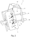
- the configuration of the discharge device 1 and the cutting tools 13 is detailed in FIGS figures 2 and 3 shown.
- the two holding devices 10, 11 extend parallel to one another and perpendicular to the crossbeam 9.
- a single cutting tool 13 is arranged on one of the holding devices 10 and two cutting tools 13 are arranged one behind the other in the direction of the longitudinal axis of the holding device on the other holding device 11.
- the length of the shafts 15 of the cutting tools 13 is dimensioned in such a way that the cutter heads 21 can dip into the tub 3 right up to the bottom. During operation, however, the cutter heads 21 should neither touch the bottom nor the wall of the tub 3.
- the distance between the three shafts 15 in a plane perpendicular to the longitudinal axes of the shafts 15 and the size of the cutter heads 21 is dimensioned such that the cutter heads 21 do not touch during operation and, if possible, act on the entire surface of the dough mass in the tub 3.
- the discharge device 1 is controlled in such a way that the cutting tools 13 are delivered to the dough in the vat 3 (see FIG figure 1 ).
- the dough is on these passed and cut off, peeled off and/or severed by means of the cutting edges.
- the block of dough is constantly reduced in size as a result.
- the separated dough initially remains in the vat 3 and falls as soon as the tilting angle is large enough onto a conveyor belt arranged below the vat or into a collecting container 22.
- the cutter heads 21 also function as a kind of retaining device. Only when the mass of dough is small enough can it pass through the space between the cutting tools 13 and fall out of the tub 3 if tilted appropriately.
- the cutting process is repeated continuously so that the block of dough becomes smaller and smaller and can therefore be discharged from the tub in small quantities. These small amounts of dough can be fed into subsequent processing devices via a dough hopper.
- the discharge device 1 uses the cutting tools 13 to prevent lumps that are too large from being discharged, which would clog the processing device. A continuous entry of the batch located in the vat 3 into the hopper of the processing device is possible.
- the arrangement of the discharge device 1 on the lift truck 2 creates a compact solution that uses existing components.
- the cutting tools 13 can rotate in opposite directions or in the same direction as each other.
- the tub 3 can also rotate in both directions and change the direction of rotation during the discharge process.
- the speed of rotation of the tub 3 and the cutting tools 13 can be constant over the entire discharge process, but can also change.
- Control and/or regulation can be carried out by means of a load applied to the electric motors of the tub 3 and/or the cutting tools 13 .
- Frequency converters are preferably provided for this purpose.
- the number of cutting tools 13 is preferably greater than two.
- the arrangement of the cutting tools 13 on the holding device 10, 11 can be adapted to the number of cutting tools 13 and the dimensions of the cutter heads 21.
- the cutter heads 21 are configured identically in the embodiment described above. However, it can also be provided that the cutter heads 21 have different sizes. Provision can also be made for further knives to be arranged on the shaft at different heights and/or for several knives to extend from the base plate, which, for example, can also additionally be canted upwards towards the shaft.
- the cutting tools are rigidly fastened to the holding device, so that they cannot rotate and the electric motors and thus additional costs can be saved.
- the retraction, in particular pivoting, of the cutting tools into the vat preferably takes place via a position control, in particular a load-controlled position control with a frequency converter.
- a position control in particular a load-controlled position control with a frequency converter.
- the dough mass discharged in small pieces falls out of the tub onto a dividing line.
- This dividing line further divides the dough mass if necessary and is used to control the size of the discharged piece of dough.
- the dividing line can be arranged between the vat and the conveyor belt or collection container.
- the height of fall between the vat and the conveyor belt or collection container is preferably at least 0.5 m, in particular at least 0.8 m. Due to the great height of fall and the associated potential energy of the dough, further comminution of the discharged dough mass on impact with the conveyor belt or the Collection container can be achieved.
- the dough has been discharged piece by piece.
- the discharge device is swiveled out of the tub. If necessary, the vat is emptied of residues and cleaned with per se known stripping devices 23, which are permanently installed on the crossbeam of the lifting tipper.
- a special program is provided for the tipping process.
- the program controls the tilting speed and rotation of the vat and/or cutters, as well as the plunge of the cutters into the vat. It can also be provided that deviations in the dough parameters can be detected and a controller adapts the program to the circumstances.
- the invention is not limited to a two-post lift truck.
- the discharge device can also be attached to a single-column lifting tipper.
- the discharge device can have an additional retaining device that prevents pieces of dough or masses that are too large from falling out of the tub.
- a restraining device would have the advantage that the size of the discharged mass could be reliably defined.
- This retaining device can be, for example, a plate or a grid covering the opening of the vat. The plate or grid has defined openings that are only permeable for a certain size of dough, so that pieces that are too large cannot fall out of the tub.
- the restraining device is preferably also attached to the holding device.
- video monitoring can also be provided, in which the sizes of the dough masses can be observed using image analysis and, if necessary, influenced the regulation of the discharge device is taken to avoid the discharge of too large pieces from the vat.
Landscapes
- Chemical & Material Sciences (AREA)
- Chemical Kinetics & Catalysis (AREA)
- Life Sciences & Earth Sciences (AREA)
- Engineering & Computer Science (AREA)
- Food Science & Technology (AREA)
- Confectionery (AREA)
- Manufacturing And Processing Devices For Dough (AREA)
Claims (14)
- Elévateur basculant (2) équipé d'un dispositif de décharge (1) affecté au déversement d'une masse alimentaire compacte à partir d'une cuve de pétrissage (3) intégrée dans ledit élévateur basculant (2), caractérisé par le fait que le dispositif de décharge (1) est muni d'au moins deux outils de sectionnement (13) dotés, à chaque fois, d'au moins deux arêtes tranchantes (20).
- Elévateur basculant selon la revendication 1, caractérisé par le fait que les outils de sectionnement (13) sont conçus pour séparer ou pour découper une masse alimentaire compacte.
- Elévateur basculant selon la revendication 1 ou 2, caractérisé par le fait que les outils de sectionnement (13), au nombre minimal de deux, sont respectivement pourvus d'au moins une tête de coupe (21), laquelle tête de coupe (21) présente les arêtes tranchantes (20).
- Elévateur basculant selon la revendication 3, caractérisé par le fait que les outils de sectionnement (13) sont munis, à chaque fois, d'une tige (15) à l'extrémité de laquelle se trouve la tête de coupe (21) à présence minimale.
- Elévateur basculant selon la revendication 4, caractérisé par le fait que la tige (21) est un arbre pouvant être entraîné au moyen d'un moteur électrique (16).
- Elévateur basculant selon la revendication 4 ou 5, caractérisé par le fait que les têtes de coupe (21) comportent, à chaque fois, une platine d'embase (17) sur laquelle la tige (15) se dresse orthogonalement et au-delà de laquelle font saillie, à la manière d'ailettes, au moins deux lames (18, 19) dont les côtés sont au moins partiellement réalisés en tant qu'arête tranchante (20).
- Elévateur basculant selon l'une des revendications précédentes, caractérisé par le fait que ledit élévateur basculant (2) est doté, en partie haute, d'une traverse (9) sur laquelle est implanté au moins un dispositif de retenue (10, 11) du dispositif de décharge (1), qui porte les outils de sectionnement (13) au nombre minimal de deux.
- Elévateur basculant selon la revendication 7, caractérisé par le fait que le dispositif de retenue (10, 11), à présence minimale, s'étend perpendiculairement à partir de la traverse (9) ; et par le fait que ledit dispositif de retenue (10, 11) à présence minimale comporte une articulation tournante (12), de façon telle qu'une extrémité dudit dispositif de retenue (10, 11) à présence minimale puisse être animée de pivotements au moyen d'un moteur électrique (14), sachant que les outils de sectionnement (13), au nombre minimal de deux, sont installés sur la partie dudit dispositif de retenue (10, 11) à présence minimale qui est vouée au pivotement.
- Elévateur basculant selon la revendication 7 ou 8, caractérisé par le fait que le dispositif de retenue (10, 11) est conçu pour introduire les outils de sectionnement (13), par pivotement, dans une cuve de pétrissage (3) fixée, avec aptitude rotatoire, sur une plate-forme élévatrice dudit élévateur basculant (2).
- Elévateur basculant selon l'une des revendications précédentes, caractérisé par le fait que ledit élévateur basculant (2) est équipé d'un dispositif de raclement (23).
- Procédé de déversement d'une masse alimentaire compacte à partir d'une cuve de pétrissage (3) intégrée dans un élévateur basculant (2), incluant les étapes opératoires suivantes :- basculement imprimé à la cuve de pétrissage (3) autour d'une axe de basculement,- introduction, dans ladite cuve de pétrissage (3), d'au moins deux outils de sectionnement (13) d'un dispositif de décharge (1) implanté sur ledit élévateur basculant (2),- mise en mouvement desdits outils de sectionnement (13), par rapport à une masse alimentaire située dans ladite cuve de pétrissage (3), de telle manière que lesdits outils de sectionnement (13) découpent ladite masse alimentaire en des morceaux de petite taille,- accroissement de l'angle de basculement de la cuve de pétrissage (3), de façon telle que les petits morceaux chutent hors de ladite cuve de pétrissage (3), et que les gros morceaux encore présents soient retenus,- extraction desdits outils de sectionnement (13) hors de ladite cuve de pétrissage (3) après l'achèvement du processus de décharge.
- Procédé selon la revendication 11, caractérisé par le fait que les outils de sectionnement (13) sont configurés de telle sorte qu'ils retiennent les gros morceaux au cours du processus de basculement.
- Procédé selon l'une des revendications 11 ou 12, caractérisé par le fait que le mouvement basculant et le mouvement relatif, ainsi que la configuration et le nombre des outils de sectionnement (13), sont adaptés à la composition de la masse alimentaire.
- Procédé selon l'une des revendications 11 à 13, caractérisé par le fait que l'introduction des outils de sectionnement (13), dans la cuve de pétrissage (3), est pilotée en adéquation avec la charge.
Priority Applications (4)
| Application Number | Priority Date | Filing Date | Title |
|---|---|---|---|
| EP18205172.2A EP3649863B1 (fr) | 2018-11-08 | 2018-11-08 | Benne élévatrice avec dispositif de sortie pour masses d'aliments compacts, en particulier de masses pour barres ou pâtes à biscuits |
| US17/291,747 US11980194B2 (en) | 2018-11-08 | 2019-11-07 | Discharge device for compact food masses, especially bar masses or cookie doughs |
| BR112021008863-6A BR112021008863A2 (pt) | 2018-11-08 | 2019-11-07 | Dispositivo de descarga para massas alimentícias compactas, em particular para massas de barra de confeitaria ou massas para biscoito |
| PCT/EP2019/080573 WO2020094802A1 (fr) | 2018-11-08 | 2019-11-07 | Dispositif de sortie pour pâtes alimentaires compactes, notamment des garnitures pour barres ou des pâtes pour biscuits |
Applications Claiming Priority (1)
| Application Number | Priority Date | Filing Date | Title |
|---|---|---|---|
| EP18205172.2A EP3649863B1 (fr) | 2018-11-08 | 2018-11-08 | Benne élévatrice avec dispositif de sortie pour masses d'aliments compacts, en particulier de masses pour barres ou pâtes à biscuits |
Publications (2)
| Publication Number | Publication Date |
|---|---|
| EP3649863A1 EP3649863A1 (fr) | 2020-05-13 |
| EP3649863B1 true EP3649863B1 (fr) | 2022-08-24 |
Family
ID=64277502
Family Applications (1)
| Application Number | Title | Priority Date | Filing Date |
|---|---|---|---|
| EP18205172.2A Active EP3649863B1 (fr) | 2018-11-08 | 2018-11-08 | Benne élévatrice avec dispositif de sortie pour masses d'aliments compacts, en particulier de masses pour barres ou pâtes à biscuits |
Country Status (4)
| Country | Link |
|---|---|
| US (1) | US11980194B2 (fr) |
| EP (1) | EP3649863B1 (fr) |
| BR (1) | BR112021008863A2 (fr) |
| WO (1) | WO2020094802A1 (fr) |
Families Citing this family (2)
| Publication number | Priority date | Publication date | Assignee | Title |
|---|---|---|---|---|
| EP3973779A1 (fr) | 2020-09-25 | 2022-03-30 | DIOSNA Dierks & Söhne GmbH | Dispositif de déchargement pour masses alimentaires compactes comportant un dispositif de vérification de la taille |
| CN112934430B (zh) * | 2021-01-25 | 2023-12-15 | 大有众和(北京)农业科技有限公司 | 一种磷肥的制备装置及方法 |
Family Cites Families (14)
| Publication number | Priority date | Publication date | Assignee | Title |
|---|---|---|---|---|
| US244924A (en) * | 1881-07-26 | Andrew a | ||
| US1486328A (en) * | 1922-09-11 | 1924-03-11 | Robert O Fraser | Food dispenser |
| US1695221A (en) * | 1927-12-14 | 1928-12-11 | Aeschbach Friedrich | Dough kneading and mixing machine |
| FR1180297A (fr) * | 1956-09-04 | 1959-06-03 | Robert Zapp Hilden K G Maschf | Désintégrateur ou broyeur |
| DE1940501U (de) | 1964-11-07 | 1966-06-16 | Kate Kemper | Vorrichtung zum entleeren von knetgut-bottichwagen od. dgl., insbesondere fuer baeckereien. |
| DE1940501A1 (de) | 1969-08-08 | 1971-02-18 | Siemens Ag | Wobbel-Messverfahren fuer Traegerfrequenz-UEbertragungssysteme,insbesondere fuer Koaxialkabelstrecken |
| DE2421104C3 (de) * | 1974-05-02 | 1981-10-29 | Dierks & Söhne, 4500 Osnabrück | Vorrichtung zum Austragen von Teig |
| IT1033020B (it) * | 1978-03-07 | 1979-07-10 | Costa Rinaldo | Macchina impastatrice in particolare utile per prodotti alimentari |
| DE4209689C2 (de) | 1992-03-25 | 2003-01-09 | Neuenkirchener Eisengieserei U | Elektromotorisch betriebene Vorrichtung zum Heben und Kippen des fahrbaren Bottichs einer Teigknetmaschine |
| US5605291A (en) * | 1994-04-28 | 1997-02-25 | Doskocil; David | Chipper/mulcher |
| US6981795B2 (en) * | 2003-07-25 | 2006-01-03 | Sylmark Holdings Limited | Multiple blade blender apparatus |
| FR2881925B1 (fr) * | 2005-02-15 | 2007-04-20 | Vmi Sa | Petrin a outils entraines par la rotation de la cuve |
| CN102058312B (zh) * | 2009-11-13 | 2013-05-22 | 深圳市牧人电器五金制品有限公司 | 一种多刀多轴果蔬搅拌机 |
| TR201002379U (tr) | 2010-03-29 | 2010-05-21 | Erna-Ma� Mak�Ne T�Caret Ve Sanay� A.�. | Birden fazla döner bıçağa sahip, kuru ve/veya sulu gıdaların parçalanmasını sağlayan el blenderi ve/veya el mikseri işlev ayağı |
-
2018
- 2018-11-08 EP EP18205172.2A patent/EP3649863B1/fr active Active
-
2019
- 2019-11-07 US US17/291,747 patent/US11980194B2/en active Active
- 2019-11-07 BR BR112021008863-6A patent/BR112021008863A2/pt not_active Application Discontinuation
- 2019-11-07 WO PCT/EP2019/080573 patent/WO2020094802A1/fr not_active Ceased
Also Published As
| Publication number | Publication date |
|---|---|
| US20220022466A1 (en) | 2022-01-27 |
| US11980194B2 (en) | 2024-05-14 |
| EP3649863A1 (fr) | 2020-05-13 |
| BR112021008863A2 (pt) | 2021-08-31 |
| WO2020094802A1 (fr) | 2020-05-14 |
Similar Documents
| Publication | Publication Date | Title |
|---|---|---|
| EP1884489B1 (fr) | Dispositif et procédé destinés à la sortie dosée d'une marchandise pouvant s'écouler ou en vrac | |
| DE69715487T2 (de) | Verfahren und Vorrichtung zum Schneiden und zur Abgabe von Teig | |
| DE9308956U1 (de) | Schneidegerät | |
| EP3649863B1 (fr) | Benne élévatrice avec dispositif de sortie pour masses d'aliments compacts, en particulier de masses pour barres ou pâtes à biscuits | |
| DE2432229A1 (de) | Vorrichtung und verfahren zum fuellen von behaeltern | |
| DE2147280C3 (de) | Vorrichtung zum Mischen von schüttbarem Erntegut | |
| EP0226925A2 (fr) | Dispositif pour couper des portions | |
| DE102012100586A1 (de) | Vorrichtung zum Schneiden und Verpacken von Brot | |
| EP0015877A1 (fr) | Dispositif de broyage d'ordures et procédé de fonctionnement dudit dispositif | |
| EP2140988B1 (fr) | Machine à découper des aliments et procédé de dépôt et de transport de tranches de produits à découper | |
| AT514646B1 (de) | Vorrichtung zur Formung eines kontinuierlichen Teigbandes | |
| DE2426025C2 (de) | Vorrichtung zur Entnahme von Viehfutter aus einem Silo | |
| EP1651051B1 (fr) | Dispositif et procédé de production d'un boudin de pâte sans abimer la pâte | |
| EP0583593A1 (fr) | Procédé et dispositif à découenner ou éplucher des produits | |
| DE2843866C2 (fr) | ||
| DE10338146B4 (de) | Anlage zur Herstellung von Teig und Gebäck | |
| WO2022063694A1 (fr) | Dispositif de décharge de masses alimentaires compactes comportant un dispositif de commande de taille | |
| DE2251457C3 (de) | Verfahren und Vorrichtung zum Homogenisieren von partikelförmigem Material | |
| DE2347392A1 (de) | Verfahren und vorrichtung zum volumetrischen dosieren von faser- oder stabfoermigen fuellguetern | |
| DE102020129751A1 (de) | Aufschneide-Maschine | |
| DE1928458A1 (de) | Vorrichtung zum Zufuehren von Schuettgut,insbesondere Vorrichtung zum Zufuehren von Erde in Ein- oder Umtopfmaschinen | |
| DE10013595B4 (de) | Elektromotorisch betriebene Vorrichtung zum Heben und Kippen eines fahrbaren Bottichs einer Teigknetmaschine | |
| DE2627301A1 (de) | Fleischschneidemaschine | |
| EP3141126A1 (fr) | Installation de traitement de pate | |
| DE881331C (de) | Hin und her bewegbare oder rotierende Aufgabevorrichtung fuer klebriges Gut, wie Kohlenschlaemme, Tonmineralien od. dgl. |
Legal Events
| Date | Code | Title | Description |
|---|---|---|---|
| PUAI | Public reference made under article 153(3) epc to a published international application that has entered the european phase |
Free format text: ORIGINAL CODE: 0009012 |
|
| STAA | Information on the status of an ep patent application or granted ep patent |
Free format text: STATUS: THE APPLICATION HAS BEEN PUBLISHED |
|
| AK | Designated contracting states |
Kind code of ref document: A1 Designated state(s): AL AT BE BG CH CY CZ DE DK EE ES FI FR GB GR HR HU IE IS IT LI LT LU LV MC MK MT NL NO PL PT RO RS SE SI SK SM TR |
|
| AX | Request for extension of the european patent |
Extension state: BA ME |
|
| STAA | Information on the status of an ep patent application or granted ep patent |
Free format text: STATUS: REQUEST FOR EXAMINATION WAS MADE |
|
| 17P | Request for examination filed |
Effective date: 20201111 |
|
| RBV | Designated contracting states (corrected) |
Designated state(s): AL AT BE BG CH CY CZ DE DK EE ES FI FR GB GR HR HU IE IS IT LI LT LU LV MC MK MT NL NO PL PT RO RS SE SI SK SM TR |
|
| STAA | Information on the status of an ep patent application or granted ep patent |
Free format text: STATUS: EXAMINATION IS IN PROGRESS |
|
| 17Q | First examination report despatched |
Effective date: 20201222 |
|
| RIC1 | Information provided on ipc code assigned before grant |
Ipc: B01F 35/75 20220101ALI20220217BHEP Ipc: A21C 1/14 20060101AFI20220217BHEP |
|
| GRAP | Despatch of communication of intention to grant a patent |
Free format text: ORIGINAL CODE: EPIDOSNIGR1 |
|
| STAA | Information on the status of an ep patent application or granted ep patent |
Free format text: STATUS: GRANT OF PATENT IS INTENDED |
|
| INTG | Intention to grant announced |
Effective date: 20220328 |
|
| GRAS | Grant fee paid |
Free format text: ORIGINAL CODE: EPIDOSNIGR3 |
|
| GRAA | (expected) grant |
Free format text: ORIGINAL CODE: 0009210 |
|
| STAA | Information on the status of an ep patent application or granted ep patent |
Free format text: STATUS: THE PATENT HAS BEEN GRANTED |
|
| AK | Designated contracting states |
Kind code of ref document: B1 Designated state(s): AL AT BE BG CH CY CZ DE DK EE ES FI FR GB GR HR HU IE IS IT LI LT LU LV MC MK MT NL NO PL PT RO RS SE SI SK SM TR |
|
| REG | Reference to a national code |
Ref country code: CH Ref legal event code: EP |
|
| REG | Reference to a national code |
Ref country code: DE Ref legal event code: R096 Ref document number: 502018010467 Country of ref document: DE |
|
| REG | Reference to a national code |
Ref country code: IE Ref legal event code: FG4D Free format text: LANGUAGE OF EP DOCUMENT: GERMAN |
|
| REG | Reference to a national code |
Ref country code: AT Ref legal event code: REF Ref document number: 1513043 Country of ref document: AT Kind code of ref document: T Effective date: 20220915 |
|
| REG | Reference to a national code |
Ref country code: LT Ref legal event code: MG9D |
|
| REG | Reference to a national code |
Ref country code: NL Ref legal event code: MP Effective date: 20220824 |
|
| PG25 | Lapsed in a contracting state [announced via postgrant information from national office to epo] |
Ref country code: SE Free format text: LAPSE BECAUSE OF FAILURE TO SUBMIT A TRANSLATION OF THE DESCRIPTION OR TO PAY THE FEE WITHIN THE PRESCRIBED TIME-LIMIT Effective date: 20220824 Ref country code: RS Free format text: LAPSE BECAUSE OF FAILURE TO SUBMIT A TRANSLATION OF THE DESCRIPTION OR TO PAY THE FEE WITHIN THE PRESCRIBED TIME-LIMIT Effective date: 20220824 Ref country code: PT Free format text: LAPSE BECAUSE OF FAILURE TO SUBMIT A TRANSLATION OF THE DESCRIPTION OR TO PAY THE FEE WITHIN THE PRESCRIBED TIME-LIMIT Effective date: 20221226 Ref country code: NO Free format text: LAPSE BECAUSE OF FAILURE TO SUBMIT A TRANSLATION OF THE DESCRIPTION OR TO PAY THE FEE WITHIN THE PRESCRIBED TIME-LIMIT Effective date: 20221124 Ref country code: NL Free format text: LAPSE BECAUSE OF FAILURE TO SUBMIT A TRANSLATION OF THE DESCRIPTION OR TO PAY THE FEE WITHIN THE PRESCRIBED TIME-LIMIT Effective date: 20220824 Ref country code: LV Free format text: LAPSE BECAUSE OF FAILURE TO SUBMIT A TRANSLATION OF THE DESCRIPTION OR TO PAY THE FEE WITHIN THE PRESCRIBED TIME-LIMIT Effective date: 20220824 Ref country code: LT Free format text: LAPSE BECAUSE OF FAILURE TO SUBMIT A TRANSLATION OF THE DESCRIPTION OR TO PAY THE FEE WITHIN THE PRESCRIBED TIME-LIMIT Effective date: 20220824 Ref country code: FI Free format text: LAPSE BECAUSE OF FAILURE TO SUBMIT A TRANSLATION OF THE DESCRIPTION OR TO PAY THE FEE WITHIN THE PRESCRIBED TIME-LIMIT Effective date: 20220824 |
|
| PG25 | Lapsed in a contracting state [announced via postgrant information from national office to epo] |
Ref country code: PL Free format text: LAPSE BECAUSE OF FAILURE TO SUBMIT A TRANSLATION OF THE DESCRIPTION OR TO PAY THE FEE WITHIN THE PRESCRIBED TIME-LIMIT Effective date: 20220824 Ref country code: IS Free format text: LAPSE BECAUSE OF FAILURE TO SUBMIT A TRANSLATION OF THE DESCRIPTION OR TO PAY THE FEE WITHIN THE PRESCRIBED TIME-LIMIT Effective date: 20221224 Ref country code: HR Free format text: LAPSE BECAUSE OF FAILURE TO SUBMIT A TRANSLATION OF THE DESCRIPTION OR TO PAY THE FEE WITHIN THE PRESCRIBED TIME-LIMIT Effective date: 20220824 Ref country code: GR Free format text: LAPSE BECAUSE OF FAILURE TO SUBMIT A TRANSLATION OF THE DESCRIPTION OR TO PAY THE FEE WITHIN THE PRESCRIBED TIME-LIMIT Effective date: 20221125 |
|
| PG25 | Lapsed in a contracting state [announced via postgrant information from national office to epo] |
Ref country code: SM Free format text: LAPSE BECAUSE OF FAILURE TO SUBMIT A TRANSLATION OF THE DESCRIPTION OR TO PAY THE FEE WITHIN THE PRESCRIBED TIME-LIMIT Effective date: 20220824 Ref country code: RO Free format text: LAPSE BECAUSE OF FAILURE TO SUBMIT A TRANSLATION OF THE DESCRIPTION OR TO PAY THE FEE WITHIN THE PRESCRIBED TIME-LIMIT Effective date: 20220824 Ref country code: ES Free format text: LAPSE BECAUSE OF FAILURE TO SUBMIT A TRANSLATION OF THE DESCRIPTION OR TO PAY THE FEE WITHIN THE PRESCRIBED TIME-LIMIT Effective date: 20220824 Ref country code: DK Free format text: LAPSE BECAUSE OF FAILURE TO SUBMIT A TRANSLATION OF THE DESCRIPTION OR TO PAY THE FEE WITHIN THE PRESCRIBED TIME-LIMIT Effective date: 20220824 Ref country code: CZ Free format text: LAPSE BECAUSE OF FAILURE TO SUBMIT A TRANSLATION OF THE DESCRIPTION OR TO PAY THE FEE WITHIN THE PRESCRIBED TIME-LIMIT Effective date: 20220824 |
|
| REG | Reference to a national code |
Ref country code: DE Ref legal event code: R097 Ref document number: 502018010467 Country of ref document: DE |
|
| PG25 | Lapsed in a contracting state [announced via postgrant information from national office to epo] |
Ref country code: SK Free format text: LAPSE BECAUSE OF FAILURE TO SUBMIT A TRANSLATION OF THE DESCRIPTION OR TO PAY THE FEE WITHIN THE PRESCRIBED TIME-LIMIT Effective date: 20220824 Ref country code: EE Free format text: LAPSE BECAUSE OF FAILURE TO SUBMIT A TRANSLATION OF THE DESCRIPTION OR TO PAY THE FEE WITHIN THE PRESCRIBED TIME-LIMIT Effective date: 20220824 |
|
| P01 | Opt-out of the competence of the unified patent court (upc) registered |
Effective date: 20230523 |
|
| PG25 | Lapsed in a contracting state [announced via postgrant information from national office to epo] |
Ref country code: MC Free format text: LAPSE BECAUSE OF FAILURE TO SUBMIT A TRANSLATION OF THE DESCRIPTION OR TO PAY THE FEE WITHIN THE PRESCRIBED TIME-LIMIT Effective date: 20220824 Ref country code: AL Free format text: LAPSE BECAUSE OF FAILURE TO SUBMIT A TRANSLATION OF THE DESCRIPTION OR TO PAY THE FEE WITHIN THE PRESCRIBED TIME-LIMIT Effective date: 20220824 |
|
| PLBE | No opposition filed within time limit |
Free format text: ORIGINAL CODE: 0009261 |
|
| REG | Reference to a national code |
Ref country code: CH Ref legal event code: PL |
|
| STAA | Information on the status of an ep patent application or granted ep patent |
Free format text: STATUS: NO OPPOSITION FILED WITHIN TIME LIMIT |
|
| GBPC | Gb: european patent ceased through non-payment of renewal fee |
Effective date: 20221124 |
|
| REG | Reference to a national code |
Ref country code: BE Ref legal event code: MM Effective date: 20221130 |
|
| PG25 | Lapsed in a contracting state [announced via postgrant information from national office to epo] |
Ref country code: LI Free format text: LAPSE BECAUSE OF NON-PAYMENT OF DUE FEES Effective date: 20221130 Ref country code: CH Free format text: LAPSE BECAUSE OF NON-PAYMENT OF DUE FEES Effective date: 20221130 |
|
| 26N | No opposition filed |
Effective date: 20230525 |
|
| PG25 | Lapsed in a contracting state [announced via postgrant information from national office to epo] |
Ref country code: SI Free format text: LAPSE BECAUSE OF FAILURE TO SUBMIT A TRANSLATION OF THE DESCRIPTION OR TO PAY THE FEE WITHIN THE PRESCRIBED TIME-LIMIT Effective date: 20220824 Ref country code: LU Free format text: LAPSE BECAUSE OF NON-PAYMENT OF DUE FEES Effective date: 20221108 |
|
| PG25 | Lapsed in a contracting state [announced via postgrant information from national office to epo] |
Ref country code: IE Free format text: LAPSE BECAUSE OF NON-PAYMENT OF DUE FEES Effective date: 20221108 Ref country code: GB Free format text: LAPSE BECAUSE OF NON-PAYMENT OF DUE FEES Effective date: 20221124 |
|
| PG25 | Lapsed in a contracting state [announced via postgrant information from national office to epo] |
Ref country code: BE Free format text: LAPSE BECAUSE OF NON-PAYMENT OF DUE FEES Effective date: 20221130 |
|
| PGFP | Annual fee paid to national office [announced via postgrant information from national office to epo] |
Ref country code: FR Payment date: 20231123 Year of fee payment: 6 |
|
| PG25 | Lapsed in a contracting state [announced via postgrant information from national office to epo] |
Ref country code: HU Free format text: LAPSE BECAUSE OF FAILURE TO SUBMIT A TRANSLATION OF THE DESCRIPTION OR TO PAY THE FEE WITHIN THE PRESCRIBED TIME-LIMIT; INVALID AB INITIO Effective date: 20181108 |
|
| PG25 | Lapsed in a contracting state [announced via postgrant information from national office to epo] |
Ref country code: CY Free format text: LAPSE BECAUSE OF FAILURE TO SUBMIT A TRANSLATION OF THE DESCRIPTION OR TO PAY THE FEE WITHIN THE PRESCRIBED TIME-LIMIT Effective date: 20220824 |
|
| PG25 | Lapsed in a contracting state [announced via postgrant information from national office to epo] |
Ref country code: MK Free format text: LAPSE BECAUSE OF FAILURE TO SUBMIT A TRANSLATION OF THE DESCRIPTION OR TO PAY THE FEE WITHIN THE PRESCRIBED TIME-LIMIT Effective date: 20220824 |
|
| PG25 | Lapsed in a contracting state [announced via postgrant information from national office to epo] |
Ref country code: TR Free format text: LAPSE BECAUSE OF FAILURE TO SUBMIT A TRANSLATION OF THE DESCRIPTION OR TO PAY THE FEE WITHIN THE PRESCRIBED TIME-LIMIT Effective date: 20220824 |
|
| PG25 | Lapsed in a contracting state [announced via postgrant information from national office to epo] |
Ref country code: BG Free format text: LAPSE BECAUSE OF FAILURE TO SUBMIT A TRANSLATION OF THE DESCRIPTION OR TO PAY THE FEE WITHIN THE PRESCRIBED TIME-LIMIT Effective date: 20220824 |
|
| PG25 | Lapsed in a contracting state [announced via postgrant information from national office to epo] |
Ref country code: MT Free format text: LAPSE BECAUSE OF FAILURE TO SUBMIT A TRANSLATION OF THE DESCRIPTION OR TO PAY THE FEE WITHIN THE PRESCRIBED TIME-LIMIT Effective date: 20220824 |
|
| REG | Reference to a national code |
Ref country code: DE Ref legal event code: R082 Ref document number: 502018010467 Country of ref document: DE Representative=s name: EGE LEE & ROIDER PATENTANWAELTE PARTGMBB, DE |
|
| REG | Reference to a national code |
Ref country code: AT Ref legal event code: MM01 Ref document number: 1513043 Country of ref document: AT Kind code of ref document: T Effective date: 20231108 |
|
| PG25 | Lapsed in a contracting state [announced via postgrant information from national office to epo] |
Ref country code: AT Free format text: LAPSE BECAUSE OF NON-PAYMENT OF DUE FEES Effective date: 20231108 |
|
| PG25 | Lapsed in a contracting state [announced via postgrant information from national office to epo] |
Ref country code: AT Free format text: LAPSE BECAUSE OF NON-PAYMENT OF DUE FEES Effective date: 20231108 |
|
| PG25 | Lapsed in a contracting state [announced via postgrant information from national office to epo] |
Ref country code: FR Free format text: LAPSE BECAUSE OF NON-PAYMENT OF DUE FEES Effective date: 20241130 |
|
| PGFP | Annual fee paid to national office [announced via postgrant information from national office to epo] |
Ref country code: DE Payment date: 20251022 Year of fee payment: 8 |
|
| PGFP | Annual fee paid to national office [announced via postgrant information from national office to epo] |
Ref country code: IT Payment date: 20251022 Year of fee payment: 8 |
|
| PGFP | Annual fee paid to national office [announced via postgrant information from national office to epo] |
Ref country code: AT Payment date: 20260410 Year of fee payment: 5 |