EP3649863B1 - Lifting tipper with discharge device for compact masses of foodstuffs, in particular bar masses or biscuit doughs - Google Patents
Lifting tipper with discharge device for compact masses of foodstuffs, in particular bar masses or biscuit doughs Download PDFInfo
- Publication number
- EP3649863B1 EP3649863B1 EP18205172.2A EP18205172A EP3649863B1 EP 3649863 B1 EP3649863 B1 EP 3649863B1 EP 18205172 A EP18205172 A EP 18205172A EP 3649863 B1 EP3649863 B1 EP 3649863B1
- Authority
- EP
- European Patent Office
- Prior art keywords
- cutting tools
- lifting
- lifting tipper
- vat
- tipper
- Prior art date
- Legal status (The legal status is an assumption and is not a legal conclusion. Google has not performed a legal analysis and makes no representation as to the accuracy of the status listed.)
- Active
Links
Images


Classifications
-
- A—HUMAN NECESSITIES
- A21—BAKING; EDIBLE DOUGHS
- A21C—MACHINES OR EQUIPMENT FOR MAKING OR PROCESSING DOUGHS; HANDLING BAKED ARTICLES MADE FROM DOUGH
- A21C1/00—Mixing or kneading machines for the preparation of dough
- A21C1/14—Structural elements of mixing or kneading machines; Parts; Accessories
- A21C1/144—Discharge mechanisms
- A21C1/1445—Discharge mechanisms using tiltable receptacles; Tilting mechanisms therefor
-
- B—PERFORMING OPERATIONS; TRANSPORTING
- B01—PHYSICAL OR CHEMICAL PROCESSES OR APPARATUS IN GENERAL
- B01F—MIXING, e.g. DISSOLVING, EMULSIFYING OR DISPERSING
- B01F35/00—Accessories for mixers; Auxiliary operations or auxiliary devices; Parts or details of general application
- B01F35/75—Discharge mechanisms
- B01F35/754—Discharge mechanisms characterised by the means for discharging the components from the mixer
- B01F35/75455—Discharge mechanisms characterised by the means for discharging the components from the mixer using a rotary discharge means, e.g. a screw beneath the receptacle
-
- B—PERFORMING OPERATIONS; TRANSPORTING
- B01—PHYSICAL OR CHEMICAL PROCESSES OR APPARATUS IN GENERAL
- B01F—MIXING, e.g. DISSOLVING, EMULSIFYING OR DISPERSING
- B01F35/00—Accessories for mixers; Auxiliary operations or auxiliary devices; Parts or details of general application
- B01F35/75—Discharge mechanisms
- B01F35/754—Discharge mechanisms characterised by the means for discharging the components from the mixer
- B01F35/7548—Discharge mechanisms characterised by the means for discharging the components from the mixer using tilting or pivoting means for emptying the mixing receptacle
-
- B—PERFORMING OPERATIONS; TRANSPORTING
- B01—PHYSICAL OR CHEMICAL PROCESSES OR APPARATUS IN GENERAL
- B01F—MIXING, e.g. DISSOLVING, EMULSIFYING OR DISPERSING
- B01F2101/00—Mixing characterised by the nature of the mixed materials or by the application field
- B01F2101/06—Mixing of food ingredients
- B01F2101/08—Mixing of dough
Definitions
- the present invention relates to a lifting tipper with a discharge device for discharging a compact food mass from a kneading tub with the features of the preamble of claim 1 and a method for discharging a compact food mass from a kneading tub arranged in a lifting tipper.
- Products such as biscuits, gingerbread and bars, in particular protein bars, chocolate bars, muesli, fruit and cereal bars and the like have a highly viscous food mass, which entails special processing requirements.
- Mixing and kneading machines for such highly viscous food masses mainly consist of a mobile vat of different sizes for masses from 120 to 1000 kg, into which a motor-driven mixing and kneading tool for carrying out the mixing and kneading process protrudes.
- the tool is extended and the vat is driven to a processing plant.
- the tub is picked up by a lifting platform of the lifting tipper, brought to the height corresponding to the size of the lifting tipper and tilted by more than 90°, so that the mass in the vat falls into the input station of a processing device arranged below, which, for example, can be designed as a funnel.
- Such a lifting tipper is, for example, from the DE 19 40 501 U1 and the DE 42 09 689 C2 out.
- the disclosure document U.S. 2010/0271900 A1 also discloses a lift truck with a mixing tool according to the preamble of claim 1.
- the processing device includes, for example, the rolling of the mass for layer-by-layer application on a conveyor belt, as is desired in the case of multi-layer products, in particular bars or biscuits. It is the object of the present invention to provide a compact lifting tipper with a discharge device for discharging a tough food mass from a kneading vat, which ensures safe and hygienic food mass guidance in fully automatic operation.
- Compact foodstuff masses are understood to mean extremely firm doughs or bar, bar or tablet masses which are highly viscous, block-forming and non-flowable.
- dried fruit bars especially date-based ones, protein-enriched sports bars, and hard cookie and gingerbread doughs have such properties.
- the cutting tools are adapted to sever, slice or peel a compact mass of food.
- the compact food mass can be processed by the cutting tools in such a way that it falls out of the vat in small portions and manual processing of the mass is no longer necessary.
- the at least two cutting tools each have at least one cutter head, with the cutter head having the cutting edges.
- the cutting tools preferably each have a rod, at the end of which the at least one cutter head is arranged.
- the rod is a shaft which can be driven, in particular by means of an electric motor. Provision can also be made for the tub to be rotatable.
- the discharge device advantageously has three cutting tools which are arranged at approximately the same distance from one another.
- the cutter heads each have a base plate on which the rod stands orthogonally and from which at least two cutters protrude like wings, the sides of which are at least partially designed as cutting edges.
- Four knives per knife head are preferably provided.
- the discharge device can have an additional retaining device that prevents pieces of dough or masses that are too large from falling out of the tub.
- a restraining device would have the advantage that the size of the discharged masses could be reliably defined.
- This retaining device can be, for example, a plate or a grid covering the opening of the vat. The plate or grid has defined openings that are only permeable for a certain size of dough, so that pieces that are too large cannot fall out of the tub.
- the lift truck can have one or two columns.
- a crossbeam is preferably provided in the upper part, on which at least one holding device of the discharge device is arranged, which carries the at least two cutting tools. It is advantageous if the at least one holding device protrudes perpendicularly from the crossbeam and the at least one holding device has a rotary joint so that one end of the at least one holding device can be pivoted by means of an electric motor, with the at least two cutting tools on the part of the at least a holding device are arranged.
- the discharge device with holding device can also be attached to a lifting platform of the lifting tipper.
- the holding device is preferably set up to pivot the cutting tools into a kneading tub rotatably mounted on a lifting platform of the lifting tipper.
- the introduction it is also conceivable for the introduction to take place linearly.
- the rods of the at least two cutting tools preferably extend perpendicularly from the associated holding device. However, an angle between, for example, 80 and 110 degrees is also conceivable.
- the lifting tipper can also have a stripping device.
- the vat is preferably tilted first and then the discharge device is moved into the vat.
- the retraction and retraction of the cutting tools is preferably a pivoting process in which the cutting tools are pivoted in and out, in particular fully automatically.
- This method allows, in a simple and efficient way, to adapt the size of a viscous mass discharged from a vat to the downstream processing devices.
- the relative movement can be produced by rotating the cutting tools and/or rotating the tub.
- the cutting tools are rigid and the modeling clay moves around the cutting tools with the rotating tub.
- the cutting tools or the cutter heads of the cutting tools are preferably designed in such a way that they hold back the large pieces during the tipping process.
- Pivoting of the cutting tools into the kneading tub is preferably load-controlled.
- video monitoring can also be provided, in which the sizes of the dough masses can be observed using image analysis and, if necessary, influenced the regulation of the discharge device is taken to avoid the discharge of too large pieces from the vat.
- the Figures 1 to 3 show a preferred embodiment of a discharge device 1, which is mounted on a lifting tipper 2.
- the processing of a highly viscous food dough is described below.
- the discharge device is also suitable for processing high-viscosity bar, stick or tablet masses, which is analogous to dough processing.
- FIG 1 a lifting tipper 2 of a dough processing plant is shown.
- a dough mixing and kneading machine (not shown) is connected upstream of the lifting tipper 2 in the production flow.
- This dough mixing and kneading machine includes a vat in which the dough is shaped by a motor-driven mixing and kneading tool. After completion of the kneading process, the vat is driven to the lifting tipper.
- FIG 1 Fig. 14 illustrates the lift-tilting operation of the lift-tipper. First, a tub 3 in the lift-tipper 2 is lifted and then tilted.
- Such lifting tippers 2 are known from the prior art in a large number.
- the base body of the lifting tipper 2 has a base plate 5 and two parallel columns 6, on the inside of which there are guideways or guide rails for a lift truck 7.
- the truck 7 overflows Rolling in guideways of the rails along a direction of travel.
- a lifting platform not shown, is arranged on the lift truck 7 and is pivotably mounted on the lift truck 7 by means of a pivot bearing.
- the tub 3 is placed on the lifting platform, which can thus be tilted via the pivot bearing.
- the tilting axis is arranged perpendicular to the direction of travel of the lift truck. The tilting can be up to 120°, in particular 135°.
- the tub 3 is rotatably mounted on the lifting platform.
- An electric motor drives the vat 3 via a gear, in particular a roller body gear, which can be in the form of a friction gear or toothed wheel gear, and the vat 3 rotates about an axis of rotation that coincides with the longitudinal axis of the vat.
- a gear in particular a roller body gear, which can be in the form of a friction gear or toothed wheel gear, and the vat 3 rotates about an axis of rotation that coincides with the longitudinal axis of the vat.
- an axis of rotation 8 is arranged between the two columns 6, on which two chain deflection wheels (not shown) are arranged, on which roller chains run.
- a drive motor (not shown) is arranged, which drives the two parallel roller chains on which the truck 7 is attached.
- the axis of rotation 8 on which the chain deflection wheels are arranged is covered by a crossbeam 9 which connects the two columns 6 to one another.
- the discharge device 1 is located on the crossbeam 9 and has two tubular holding devices 10, 11, each of which has a swivel joint 12 and on which drivable cutting tools 13 are held.
- the two holding devices of the discharge device 10 , 11 can each be pivoted about the rotary joint 12 by means of a linear drive 14 .
- the cutting tool 13 is arranged on the pivotable part of the holding device 10,11.
- the linear drives 14 allow the cutting tools 13 to pivot into the tub 3 during the tipping process.
- the cutting tools 13 arranged on the holding devices 10, 11 each have a shaft 15 which can be driven in each case by an associated electric motor 16 via a reduction gear.
- the electric motors 16 sit on the corresponding holding device 10,11.
- the shafts 15 preferably extend perpendicular to the longitudinal axis of the holding device 10,11.
- a base plate 17 is arranged in each case, on which the shaft 15 is orthogonal.
- Four knives 18, 19 protrude like wings from the base plate 17, which are approximately rectangular and form cutting edges 20 on their longitudinal sides.
- the knives 18, 19 project outwards from the shaft 15. Two of the four blades 19 are angled downwards, starting from the base plate 17 and away from the shaft 15 .
- the two further knives 18 are angled upwards towards the shaft 15 .
- Two knives 18, 19 angled in opposite directions form an approximately V-shaped pair of knives.
- the knives 18, 19 preferably extend with their long sides parallel to one another.
- the base plate 17 and the knives 18, 19 form a knife head 21 of the cutting tool 13.
- the cutter head 21 is preferably made of stainless steel.
- the configuration of the discharge device 1 and the cutting tools 13 is detailed in FIGS figures 2 and 3 shown.
- the two holding devices 10, 11 extend parallel to one another and perpendicular to the crossbeam 9.
- a single cutting tool 13 is arranged on one of the holding devices 10 and two cutting tools 13 are arranged one behind the other in the direction of the longitudinal axis of the holding device on the other holding device 11.
- the length of the shafts 15 of the cutting tools 13 is dimensioned in such a way that the cutter heads 21 can dip into the tub 3 right up to the bottom. During operation, however, the cutter heads 21 should neither touch the bottom nor the wall of the tub 3.
- the distance between the three shafts 15 in a plane perpendicular to the longitudinal axes of the shafts 15 and the size of the cutter heads 21 is dimensioned such that the cutter heads 21 do not touch during operation and, if possible, act on the entire surface of the dough mass in the tub 3.
- the discharge device 1 is controlled in such a way that the cutting tools 13 are delivered to the dough in the vat 3 (see FIG figure 1 ).
- the dough is on these passed and cut off, peeled off and/or severed by means of the cutting edges.
- the block of dough is constantly reduced in size as a result.
- the separated dough initially remains in the vat 3 and falls as soon as the tilting angle is large enough onto a conveyor belt arranged below the vat or into a collecting container 22.
- the cutter heads 21 also function as a kind of retaining device. Only when the mass of dough is small enough can it pass through the space between the cutting tools 13 and fall out of the tub 3 if tilted appropriately.
- the cutting process is repeated continuously so that the block of dough becomes smaller and smaller and can therefore be discharged from the tub in small quantities. These small amounts of dough can be fed into subsequent processing devices via a dough hopper.
- the discharge device 1 uses the cutting tools 13 to prevent lumps that are too large from being discharged, which would clog the processing device. A continuous entry of the batch located in the vat 3 into the hopper of the processing device is possible.
- the arrangement of the discharge device 1 on the lift truck 2 creates a compact solution that uses existing components.
- the cutting tools 13 can rotate in opposite directions or in the same direction as each other.
- the tub 3 can also rotate in both directions and change the direction of rotation during the discharge process.
- the speed of rotation of the tub 3 and the cutting tools 13 can be constant over the entire discharge process, but can also change.
- Control and/or regulation can be carried out by means of a load applied to the electric motors of the tub 3 and/or the cutting tools 13 .
- Frequency converters are preferably provided for this purpose.
- the number of cutting tools 13 is preferably greater than two.
- the arrangement of the cutting tools 13 on the holding device 10, 11 can be adapted to the number of cutting tools 13 and the dimensions of the cutter heads 21.
- the cutter heads 21 are configured identically in the embodiment described above. However, it can also be provided that the cutter heads 21 have different sizes. Provision can also be made for further knives to be arranged on the shaft at different heights and/or for several knives to extend from the base plate, which, for example, can also additionally be canted upwards towards the shaft.
- the cutting tools are rigidly fastened to the holding device, so that they cannot rotate and the electric motors and thus additional costs can be saved.
- the retraction, in particular pivoting, of the cutting tools into the vat preferably takes place via a position control, in particular a load-controlled position control with a frequency converter.
- a position control in particular a load-controlled position control with a frequency converter.
- the dough mass discharged in small pieces falls out of the tub onto a dividing line.
- This dividing line further divides the dough mass if necessary and is used to control the size of the discharged piece of dough.
- the dividing line can be arranged between the vat and the conveyor belt or collection container.
- the height of fall between the vat and the conveyor belt or collection container is preferably at least 0.5 m, in particular at least 0.8 m. Due to the great height of fall and the associated potential energy of the dough, further comminution of the discharged dough mass on impact with the conveyor belt or the Collection container can be achieved.
- the dough has been discharged piece by piece.
- the discharge device is swiveled out of the tub. If necessary, the vat is emptied of residues and cleaned with per se known stripping devices 23, which are permanently installed on the crossbeam of the lifting tipper.
- a special program is provided for the tipping process.
- the program controls the tilting speed and rotation of the vat and/or cutters, as well as the plunge of the cutters into the vat. It can also be provided that deviations in the dough parameters can be detected and a controller adapts the program to the circumstances.
- the invention is not limited to a two-post lift truck.
- the discharge device can also be attached to a single-column lifting tipper.
- the discharge device can have an additional retaining device that prevents pieces of dough or masses that are too large from falling out of the tub.
- a restraining device would have the advantage that the size of the discharged mass could be reliably defined.
- This retaining device can be, for example, a plate or a grid covering the opening of the vat. The plate or grid has defined openings that are only permeable for a certain size of dough, so that pieces that are too large cannot fall out of the tub.
- the restraining device is preferably also attached to the holding device.
- video monitoring can also be provided, in which the sizes of the dough masses can be observed using image analysis and, if necessary, influenced the regulation of the discharge device is taken to avoid the discharge of too large pieces from the vat.
Landscapes
- Chemical & Material Sciences (AREA)
- Chemical Kinetics & Catalysis (AREA)
- Life Sciences & Earth Sciences (AREA)
- Engineering & Computer Science (AREA)
- Food Science & Technology (AREA)
- Confectionery (AREA)
- Manufacturing And Processing Devices For Dough (AREA)
Description
Die vorliegende Erfindung betrifft einen Hebekipper mit einer Austragsvorrichtung zum Austrag einer kompakten Nahrungsmittelmasse aus einem Knetbottich mit den Merkmalen des Oberbegriffs des Anspruchs 1 sowie ein Verfahren zum Austragen einer kompakten Nahrungsmittelmasse aus einem in einem Hebekipper angeordneten Knetbottich.The present invention relates to a lifting tipper with a discharge device for discharging a compact food mass from a kneading tub with the features of the preamble of
Produkte wie Kekse, Lebkuchen, und Riegel, insbesondere Proteinriegel, Schoko-, Müsli, Frucht- und Cerealienriegel und dergleichen weisen eine hochviskose Nahrungsmittelmasse auf, die bei der Verarbeitung besondere Anforderungen mit sich bringt.Products such as biscuits, gingerbread and bars, in particular protein bars, chocolate bars, muesli, fruit and cereal bars and the like have a highly viscous food mass, which entails special processing requirements.
Misch- und Knetmaschinen für solche hochviskosen Nahrungsmittelmassen bestehen vorwiegend aus einem fahrbaren Bottich unterschiedlicher Größe für Massen von 120 bis 1000 Kg, in den jeweils ein motorisch antreibbares Misch- und Knetwerkzeug zur Durchführung des Misch- und Knetvorganges hineinragt. Nach Beendigung des Knetvorganges wird das Werkzeug ausgefahren und der Bottich zu einer Verarbeitungsanlage gefahren. Mit Hilfe eines Hebekippers wird der Bottich von einer Hebebühne des Hebekippers erfasst, auf die der Größe des Hebekippers entsprechenden Höhe gebracht und um mehr als 90° gekippt, so dass das die im Bottich befindliche Masse in die darunter angeordnete Eingangsstation einer Bearbeitungsvorrichtung fällt, welche beispielsweise als ein Trichter ausgebildet sein kann. Ein solcher Hebekipper geht beispielsweise aus der
Hochviskose Nahrungsmittelmassen sind nicht fließfähig. Beim Knetvorgang bildet sich ein großer Nahrungsmittelmassen-Block aus. Dieser wird herkömmlicherweise bei dem Austrag aus dem Hebekipper durch Bedienpersonal manuell zerkleinert, um einzelne kleinere Teigstücke für die Weiterbearbeitung in der Bearbeitungsvorrichtung bereitzustellen. Denn es besteht die Gefahr, dass die Öffnung des Trichters teilweise oder ganz durch die Masse verstopft wird. Die Bearbeitungsvorrichtung umfasst beispielsweise das Walzen der Masse zum lagenweisen Auftragen auf ein Fließband, wie das bei mehrlagigen Produkten, insbesondere Riegeln oder Keksen gewünscht ist. Es ist Aufgabe der vorliegenden Erfindung einen kompakten Hebekipper mit einer Austragsvorrichtung zum Austrag einer zähen Nahrungsmittelmasse aus einem Knetbottich bereitzustellen, welcher in vollautomatischem Betrieb eine sichere und hygienische Nahrungsmittelmassenführung gewährleistet.Highly viscous food masses are not flowable. A large block of food mass is formed during the kneading process. This is conventionally comminuted manually by operating personnel when it is discharged from the lifting tipper in order to provide individual, smaller pieces of dough for further processing in the processing device. Because there is a risk that the opening of the funnel will be partially or completely blocked by the mass. The processing device includes, for example, the rolling of the mass for layer-by-layer application on a conveyor belt, as is desired in the case of multi-layer products, in particular bars or biscuits. It is the object of the present invention to provide a compact lifting tipper with a discharge device for discharging a tough food mass from a kneading vat, which ensures safe and hygienic food mass guidance in fully automatic operation.
Diese Aufgabe wird von einem Hebekipper mit einer Austragsvorrichtung zum Austrag einer kompakten Nahrungsmittelmasse aus einem Knetbottich mit den Merkmalen des Anspruchs 1 und von einem Verfahren zum Austragen einer kompakten Nahrungsmittelmasse aus einem in einem Hebekipper angeordneten Knetbottich mit den Merkmalen des Anspruchs 11 gelöst. Vorteilhafte Ausgestaltungen und Weiterbildungen der Erfindung ergeben sich aus den abhängigen Ansprüchen.This object is achieved by a lifting tipper with a discharge device for discharging a compact food mass from a kneading tub with the features of
Unter kompakter Nahrungsmittelmasse werden extrem feste Teige oder Riegel-, Stangen- oder Tafelmassen verstanden, die hochviskose, blockbildend und nicht fließfähig sind. Riegelmassen aus Trockenfrüchten, insbesondere auf Dattelbasis, mit Proteinen angereichte Sport-Riegelmassen und Hartkeks- und Lebkuchenteige haben beispielsweise solche Eigenschaften.Compact foodstuff masses are understood to mean extremely firm doughs or bar, bar or tablet masses which are highly viscous, block-forming and non-flowable. For example, dried fruit bars, especially date-based ones, protein-enriched sports bars, and hard cookie and gingerbread doughs have such properties.
Es ist ein Hebekipper mit einer Austragsvorrichtung zum Austrag einer kompakten Nahrungsmittelmasse aus einem in dem Hebekipper angeordneten Knetbottich, vorgesehen, der wenigstens zwei Schneidwerkzeuge aufweist, die jeweils wenigstens zwei Schneidkanten aufweisen. Vorzugsweise sind die Schneidwerkzeuge dazu eingerichtet, eine kompakte Nahrungsmittelmasse zu durchtrennen, zu zerschneiden oder abzuschälen. Die kompakte Nahrungsmittelmasse kann durch die Schneidwerkzeuge so bearbeitet werden, dass sie in kleinen Portionen aus dem Bottich fällt und eine manuelle Bearbeitung der Masse nicht mehr notwendig ist.There is a lifting tipper with a discharge device for discharging a compact mass of food from a kneading tub arranged in the lifting tipper, provided which has at least two cutting tools which each have at least two cutting edges. Preferably, the cutting tools are adapted to sever, slice or peel a compact mass of food. The compact food mass can be processed by the cutting tools in such a way that it falls out of the vat in small portions and manual processing of the mass is no longer necessary.
Es ist vorteilhaft, wenn die wenigstens zwei Schneidwerkzeuge jeweils wenigstens einen Messerkopf haben, wobei der Messerkopf die Schneidkanten aufweist.It is advantageous if the at least two cutting tools each have at least one cutter head, with the cutter head having the cutting edges.
Vorzugsweise weisen die Schneidwerkzeuge jeweils eine Stange auf, an deren Ende der wenigstens eine Messerkopf angeordnet ist. In einer Ausführungsform kann vorgesehen sein, dass die Stange eine Welle ist, die, insbesondere mittels eines Elektromotors antreibbar ist. Es kann auch vorgesehen sein, dass der Bottich drehbar ist.The cutting tools preferably each have a rod, at the end of which the at least one cutter head is arranged. In one embodiment it can be provided that the rod is a shaft which can be driven, in particular by means of an electric motor. Provision can also be made for the tub to be rotatable.
Vorteilhafterweise weist die Austragsvorrichtung drei Schneidwerkzeuge auf, die etwa in einem gleichen Abstand zueinander angeordnet sind.The discharge device advantageously has three cutting tools which are arranged at approximately the same distance from one another.
Es ist vorteilhaft, wenn die Messerköpfe der Schneidwerkzeuge in einer gemeinsamen Ebene liegen.It is advantageous if the cutter heads of the cutting tools are in a common plane.
In einer Ausführungsform weisen die Messerköpfe jeweils eine Grundplatte auf, auf der die Stange orthogonal steht und von der flügelartig wenigstens zwei Messer hervorragen, deren Seiten zumindest teilweise als Schneidkante ausgebildet sind. Bevorzugt sind vier Messer pro Messerkopf vorgesehen.In one embodiment, the cutter heads each have a base plate on which the rod stands orthogonally and from which at least two cutters protrude like wings, the sides of which are at least partially designed as cutting edges. Four knives per knife head are preferably provided.
Ganz allgemein kann die Austragsvorrichtung eine zusätzliche Rückhaltevorrichtung aufweisen, die verhindert, dass zu große Teigstücke bzw. Massen aus dem Bottich fallen. Eine solche Rückhaltevorrichtung hätte den Vorteil, dass die Größe der ausgetragenen Massen zuverlässig definiert werden könnte. Diese Rückhaltevorrichtung kann beispielsweise eine Platte oder ein Gitter sein, die die Öffnung des Bottichs abdecken. Die Platte oder das Gitter weisen dabei definierte Öffnungen auf, die nur für eine bestimmte Teiggröße durchlässig sind, so dass zu große Stücke nicht aus dem Bottich fallen können.In very general terms, the discharge device can have an additional retaining device that prevents pieces of dough or masses that are too large from falling out of the tub. Such a restraining device would have the advantage that the size of the discharged masses could be reliably defined. This retaining device can be, for example, a plate or a grid covering the opening of the vat. The plate or grid has defined openings that are only permeable for a certain size of dough, so that pieces that are too large cannot fall out of the tub.
Der Hebekipper kann eine oder zwei Säulen aufweisen.The lift truck can have one or two columns.
Vorzugsweise ist bei einem Zweisäulen-Hebekipper im oberen Teil ein Querbalken vorgesehen, an dem wenigstens eine Haltevorrichtung der Austragsvorrichtung angeordnet ist, die die wenigstens zwei Schneidwerkzeuge trägt. Dabei ist es vorteilhaft, wenn die wenigstens eine Haltevorrichtung senkrecht von dem Querbalken abgeht und die wenigstens eine Haltevorrichtung ein Drehgelenk aufweist, so dass ein Ende der wenigstens einen Haltevorrichtung mittels eines Elektromotors verschwenkbar ist, wobei die wenigstens zwei Schneidwerkzeuge an dem zu verschwenkenden Teil der wenigstens einen Haltevorrichtung angeordnet sind.In the case of a two-column lifting tipper, a crossbeam is preferably provided in the upper part, on which at least one holding device of the discharge device is arranged, which carries the at least two cutting tools. It is advantageous if the at least one holding device protrudes perpendicularly from the crossbeam and the at least one holding device has a rotary joint so that one end of the at least one holding device can be pivoted by means of an electric motor, with the at least two cutting tools on the part of the at least a holding device are arranged.
Die Austragsvorrichtung mit Haltevorrichtung kann auch an einer Hebebühne des Hebekippers befestigt sein.The discharge device with holding device can also be attached to a lifting platform of the lifting tipper.
Vorzugsweise ist die Haltevorrichtung dazu eingerichtet, die Schneidwerkzeuge in einen auf einer Hebebühne des Hebekippers drehbar befestigten Knetbottich einzuschwenken. Es ist aber auch denkbar, dass die Einführung linear erfolgt.The holding device is preferably set up to pivot the cutting tools into a kneading tub rotatably mounted on a lifting platform of the lifting tipper. However, it is also conceivable for the introduction to take place linearly.
Die Stäbe der wenigstens zwei Schneidwerkzeuge gehen bevorzugt senkrecht von der zugeordneten Haltevorrichtung ab. Es ist aber auch ein Winkel zwischen beispielsweise 80 und 110 Grad denkbar.The rods of the at least two cutting tools preferably extend perpendicularly from the associated holding device. However, an angle between, for example, 80 and 110 degrees is also conceivable.
Der Hebekipper kann zusätzlich eine Ausschälvorrichtung aufweisen.The lifting tipper can also have a stripping device.
Weiterhin ist ein Verfahren zum Austragen einer kompakten Nahrungsmittelmasse aus einem in einem Hebekipper angeordneten Knetbottich mit folgenden Verfahrensschritten vorgesehen:
- Verkippen des Knetbottichs um eine Kippachse,
- Einfahren wenigstens zweier Schneidwerkzeuge einer an dem Hebekipper angeordneten Austragsvorrichtung in den Knetbottich,
- Bewegen der Schneidwerkzeuge relativ zu einer im Knetbottich befindlichen Nahrungsmittelmasse, derart, dass die Schneidwerkzeuge die Nahrungsmittelmasse in kleinere Stücke schneiden,
- Vergrößerung des Kippwinkels des Knetbottichs, derart, dass die kleinen Stücke aus dem Knetbottich fallen und die noch vorhandenen großen Stücke zurückgehalten werden,
- Nach Beendigung des Austragsvorgangs Herausfahren der Schneidwerkzeuge aus dem Knetbottich.
- Tilting the kneading tub around a tilting axis,
- Driving in at least two cutting tools of a discharge device arranged on the lifting tipper into the kneading tub,
- Moving the cutting tools relative to a mass of food in the kneading tub in such a way that the cutting tools cut the mass of food into smaller pieces,
- increasing the tilting angle of the kneading bowl in such a way that the small pieces fall out of the kneading bowl and the large pieces that are still present are retained,
- After completion of the discharge process, the cutting tools are moved out of the kneading vat.
Bevorzugt wird dabei zuerst der Bottich gekippt und darauffolgend die Austragsvorrichtung in den Bottich bewegt. Eine andere Reihenfolge ist aber auch möglich. Bei dem Ein- und Herausfahren der Schneidwerkzeuge handelt es sich bevorzugt um einen Schwenkvorgang, bei dem die Schneidwerkzeuge, insbesondere vollautomatisch, ein- und ausgeschwenkt werden.The vat is preferably tilted first and then the discharge device is moved into the vat. However, a different order is also possible. The retraction and retraction of the cutting tools is preferably a pivoting process in which the cutting tools are pivoted in and out, in particular fully automatically.
Dieses Verfahren erlaubt auf einfache und effiziente Weise, die Größe einer aus einem Bottich ausgetragenen zähen Masse an die nachgeschalteten Bearbeitungsvorrichtungen anzupassen.This method allows, in a simple and efficient way, to adapt the size of a viscous mass discharged from a vat to the downstream processing devices.
Die Relativbewegung kann durch Drehung der Schneidwerkzeuge und/oder Drehung des Bottichs hergestellt werden. Es kann aber auch vorgesehen sein, dass die Schneidwerkzeuge starr ausgebildet sind und sich die Knetmasse mit dem drehenden Bottich um die Schneidwerkzeuge herum bewegt.The relative movement can be produced by rotating the cutting tools and/or rotating the tub. However, it can also be provided that the cutting tools are rigid and the modeling clay moves around the cutting tools with the rotating tub.
Vorzugsweise sind die Schneidwerkzeuge bzw. die Messerköpfe der Schneidwerkzeuge so ausgestaltet, dass sie während des Kippvorgangs die großen Stücke zurückhalten.The cutting tools or the cutter heads of the cutting tools are preferably designed in such a way that they hold back the large pieces during the tipping process.
Es ist vorteilhaft, wenn die Kippbewegung und die Relativbewegung, sowie die Ausgestaltung und die Anzahl der Schneidwerkzeuge an die Zusammensetzung der Nahrungsmittelmasse angepasst sind.It is advantageous if the tilting movement and the relative movement, as well as the configuration and the number of cutting tools, are adapted to the composition of the food mass.
Vorzugsweise ist das Einschwenken der Schneidwerkzeuge in den Knetbottich lastgesteuert.Pivoting of the cutting tools into the kneading tub is preferably load-controlled.
Um die Zuverlässigkeit der Austragsvorrichtung zu erhöhen, kann auch eine Videoüberwachung vorgesehen sein, bei der anhand von Bildanalyse die Größen der Teigmassen beobachtet werden und falls notwendig Einfluss auf die Regelung der Austragsvorrichtung genommen wird, um das Austragen von zu großen Stücke aus dem Bottich zu vermeiden.In order to increase the reliability of the discharge device, video monitoring can also be provided, in which the sizes of the dough masses can be observed using image analysis and, if necessary, influenced the regulation of the discharge device is taken to avoid the discharge of too large pieces from the vat.
Eine bevorzugte Ausführungsform der Erfindung wird nachfolgend anhand der Zeichnungen näher erläutert. Gleichartige oder gleichwirkende Bauteile werden in den Figuren mit denselben Bezugszeichen bezeichnet. Es zeigen:
- Figur 1:
- eine schematische Darstellung eines Hebekippers mit Austragsvorrichtung in unterschiedlichen Positionen,
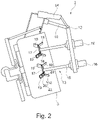
- Figur 2:
- eine Seitenansicht der Austragsvorrichtung aus
Figur 1 mit Schneidwerkzeugen, sowie - Figur 3:
- eine Draufsicht auf die
Austragsvorrichtung aus Figur 2 mit vereinfacht dargestelltem Hebekipper und Bottich.
- Figure 1:
- a schematic representation of a lifting tipper with discharge device in different positions,
- Figure 2:
- a side view of the discharge device
figure 1 with cutting tools, as well - Figure 3:
- a plan view of the discharge device
figure 2 with a simplified lifting tipper and vat.
Die
In der
Der Grundkörper des Hebekippers 2 weist eine Bodenplatte 5 und zwei parallele Säulen 6 auf, an deren Innenseiten sich Führungsbahnen oder Führungsschienen für einen Hubwagen 7 befinden. Der Hubwagen 7 läuft über Rollen in Führungsbahnen der Schienen entlang einer Verfahrrichtung. Zur Lastaufnahme ist auf dem Hubwagen 7 eine nicht dargestellte Hebebühne angeordnet, die an dem Hubwagen 7 mittels eines Drehlagers schwenkbar gelagert ist. Auf der Hebebühne ist der Bottich 3 platziert, der somit über das Drehlager verkippbar ist. Die Kippachse ist senkrecht zur Verfahrrichtung des Hubwagens angeordnet. Die Verkippung kann bis zu 120°, insbesondere 135° betragen. Der Bottich 3 ist drehbar auf der Hebebühne befestigt. Ein Elektromotor treibt über ein Getriebe, insbesondere ein Wälzkörpergetriebe, das als Reibradgetriebe oder Zahnradgetriebe ausgeformt sein kann, den Bottich 3 an, der sich um eine Rotationsachse, die mit der Längsachse des Bottichs übereinstimmt, dreht.The base body of the lifting
Im oberen Teil des Hebekippers 2 ist zwischen den beiden Säulen 6 eine Drehachse 8 angeordnet, auf der zwei nicht dargestellte Kettenumlenkräder angeordnet sind, auf denen Rollenketten laufen. Im unteren oder oberen Teil des Hebekippers ist ein nicht dargestellter Antriebsmotor angeordnet, der die zwei parallellaufenden Rollenketten, an der der Hubwagen 7 befestigt ist, antreibt.In the upper part of the lifting
Die Drehachse 8 auf der die Kettenumlenkräder angeordnet sind ist von einem Querbalken 9 überdeckt, der die beiden Säulen 6 miteinander verbindet. An dem Querbalken 9 befinden sich die Austragsvorrichtung 1, aufweisend zwei rohrförmige Haltevorrichtungen 10,11, die jeweils ein Drehgelenk 12 aufweisen und an denen antreibbare Schneidwerkzeuge 13 gehalten sind. Die zwei Haltevorrichtungen der Austragsvorrichtung 10,11 sind jeweils um das Drehgelenk 12 mittels eines Linearantriebs 14 verschwenkbar. Das Schneidwerkzeug 13 ist dabei an dem verschenkbaren Teil der Haltevorrichtung 10,11 angeordnet. Die Linearantriebe 14 erlauben ein Einschwenken der Schneidwerkzeuge 13 in den Bottich 3 während des Kippvorgangs. Die an den Haltevorrichtungen 10,11 angeordneten Schneidwerkzeuge 13 weisen jeweils eine Welle 15 auf, die jeweils von einem zugeordneten Elektromotor 16 über ein Untersetzungsgetriebe angetrieben werden kann. Die Elektromotoren 16 sitzen dabei auf der entsprechenden Haltevorrichtung 10,11. Die Wellen 15 erstrecken sich bevorzugt senkrecht zur Längsachse der Haltevorrichtung 10,11. An den motorfernen Enden der Wellen ist jeweils eine Grundplatte 17 angeordnet, auf der die Welle 15 orthogonal steht. Von der Grundplatte 17 stehen flügelartig vier Messer 18,19 hervor, die in etwa rechteckig sind und deren Längsseiten Schneidkanten 20 ausbilden. Die Messer 18,19 stehen dabei nach außen von der Welle 15 ab. Zwei der vier Messer 19 sind von der Grundplatte 17 ausgehend nach unten, von der Welle 15 weg abgewinkelt. Die zwei weiteren Messer 18 sind von der Grundplatte 17 ausgehend nach oben, zur Welle 15 hin abgewinkelt. Zwei entgegengesetzt abgewinkelte Messer 18,19 bilden dabei ein in etwa v-förmiges Messerpaar. In Umfangsrichtung um die Welle 15 sind die Messerpaare gegenüberliegend ausgebildet. Die Messer 18,19 erstrecken sich mit ihren Längsseiten bevorzugt parallel zueinander. Die Grundplatte 17 und die Messer 18,19 bilden einen Messerkopf 21 des Schneidwerkzeugs 13 aus. Der Messerkopf 21 ist bevorzugt aus Edelstahl gebildet. Die Ausgestaltung der Austragsvorrichtung 1 und der Schneidwerkzeuge 13 ist im Detail in den
Die beiden Haltevorrichtungen 10,11 erstrecken sich parallel zueinander und senkrecht zu dem Querbalken 9. Auf einer der Haltevorrichtungen 10 ist ein einziges Schneidwerkzeug 13 angeordnet und auf der anderen Haltevorrichtung 11 sind, in Richtung der Längsachse der Haltevorrichtung hintereinanderliegend, zwei Schneidwerkzeuge 13 angeordnet. Die Länge der Wellen 15 der Schneidwerkzeuge 13 ist so dimensioniert, dass die Messerköpfe 21 in den Bottich 3 bis in unmittelbare Nähe des Bodens eintauchen können. Während des Betriebs sollten die Messerköpfe 21 aber weder den Boden, noch die Wandung des Bottichs 3 berühren. Der Abstand der drei Wellen 15 in einer Ebene senkrecht zu den Längsachsen der Wellen 15 und die Größe der Messerköpfe 21 ist so dimensioniert, dass die Messerköpfe 21 sich im Betrieb nicht berühren und möglichst auf die gesamte Oberfläche der sich im Bottich 3 befindenden Teigmasse einwirken. Je größer der Durchmesser einer Einhüllenden der Messerköpfe 21 ist, desto besser ist das Ergebnis der Teigbearbeitung.The two
Während des Kippvorgangs des Hebekippers 2 wird die Austragsvorrichtung 1 derart gesteuert, dass die Schneidwerkzeuge 13 auf den im Bottich 3 befindlichen Teig zugestellt werden (siehe
Es kann vorgesehen sein, dass die Relativbewegung durch Drehung des Bottichs 3 und/oder der Schneidwerkzeuge 13 erfolgt. Die Schneidwerkzeuge 13 können sich untereinander in entgegengesetzte oder in dieselbe Richtung drehen. Der Bottich 3 kann sich ebenfalls in beide Richtungen drehen und während des Austragsvorgangs die Drehrichtung ändern. Die Geschwindigkeit der Drehungen des Bottichs 3 und der Schneidwerkzeuge 13 kann über den gesamten Austragsvorgang konstant sein, sich aber auch ändern. Es kann eine Steuerung und/oder Regelung mittels einer an den Elektromotoren des Bottichs 3 und/oder der Schneidwerkzeuge 13 anliegenden Last vorgenommen werden. Dazu sind bevorzugt Frequenzumrichter vorgesehen. Die Anzahl der Schneidwerkzeuge 13 ist bevorzugt größer als zwei. Die Anordnung der Schneidwerkzeuge 13 auf der Haltevorrichtung 10,11 kann dabei an die Anzahl der Schneidwerkzeuge 13 und die Dimensionierung der Messerköpfe 21 angepasst werden.Provision can be made for the relative movement to take place by rotating the
Die Messerköpfe 21 sind in der zuvor beschriebenen Ausführungsform identisch ausgestaltet. Es kann aber auch vorgesehen sein, dass die Messerköpfe 21 unterschiedliche Größen haben. Es kann auch vorgesehen sein, dass an der Welle auf unterschiedlichen Höhen weitere Messer angeordnet sind und/oder das von der Grundplatte mehrere Messer abgehen, die beispielsweise auch zusätzlich nach oben, zur Welle hin, gekantet sein können.The cutter heads 21 are configured identically in the embodiment described above. However, it can also be provided that the cutter heads 21 have different sizes. Provision can also be made for further knives to be arranged on the shaft at different heights and/or for several knives to extend from the base plate, which, for example, can also additionally be canted upwards towards the shaft.
In einer Ausführungsform kann auch vorgesehen sein, dass die Schneidwerkzeuge starr an der Haltevorrichtung befestigt sind, so dass sie sich nicht drehen können und die Elektromotoren und dadurch zusätzliche Kosten eingespart werden können.In one embodiment it can also be provided that the cutting tools are rigidly fastened to the holding device, so that they cannot rotate and the electric motors and thus additional costs can be saved.
Das Einfahren, insbesondere Einschwenken, der Schneidwerkzeuge in den Bottich erfolgt bevorzugt über eine Positionsregelung, insbesondere eine lastgesteuerte Positionsregelung mit Frequenzumrichter. Dadurch kann das Eintauchen der Messerköpfe in den Bottich so optimiert werden, dass diese lediglich auf die Oberfläche des Teiges einwirken und nicht soweit in den Teig eindringen, dass ein Blockieren der Messerköpfe oder ein Verklumpen der Messerköpfe verhindert werden kann. Zudem kann so sichergestellt, dass die abgetrennten Teigmassen eine gewisse Größe nicht überschreiten.The retraction, in particular pivoting, of the cutting tools into the vat preferably takes place via a position control, in particular a load-controlled position control with a frequency converter. As a result, the immersion of the cutter heads in the tub can be optimized in such a way that they only act on the surface of the dough and do not penetrate so far into the dough that blocking of the cutter heads or clumping of the cutter heads can be prevented. In addition, it can be ensured in this way that the separated dough masses do not exceed a certain size.
Es kann zudem allgemein vorgesehen sein, dass die in kleinen Stücken ausgetragene Teigmasse aus dem Bottich auf einen Trennstrich fällt. Dieser Trennstrich zerteilt die Teigmasse bei Bedarf weiter und dient der Größenkontrolle des ausgetragenen Teigstücks. Der Trennstrich kann dabei zwischen Bottich und Fließband oder Auffangbehälter angeordnet sein. Die Fallhöhe zwischen Bottich und Fließband oder Auffangbehälter ist dabei bevorzugt mindestens 0,5 m, insbesondere mindestens 0,8 m. Durch die große Fallhöhe und die damit einhergehende potentielle Energie des Teigs kann eine weitere Zerkleinerung der ausgetragenen Teigmasse bei Aufprall auf das Fließband oder den Auffangbehälter erzielt werden.In addition, it can generally be provided that the dough mass discharged in small pieces falls out of the tub onto a dividing line. This dividing line further divides the dough mass if necessary and is used to control the size of the discharged piece of dough. The dividing line can be arranged between the vat and the conveyor belt or collection container. The height of fall between the vat and the conveyor belt or collection container is preferably at least 0.5 m, in particular at least 0.8 m. Due to the great height of fall and the associated potential energy of the dough, further comminution of the discharged dough mass on impact with the conveyor belt or the Collection container can be achieved.
Es kann bei der Beschickung der Bearbeitungsvorrichtung von dem Fließband aus ebenfalls eine entsprechend große Fallhöhe vorgesehen sein. Die Teigmasse fällt von dem Fließband auf den Trichter und wird durch die potentielle Energie weiter zerkleinert.When loading the processing device from the conveyor belt, a correspondingly large fall height can also be provided. the Dough mass falls from the conveyor belt onto the hopper and is further broken up by the potential energy.
Am Ende des Kippvorgangs ist der Teig Stück für Stück ausgetragen worden. Die Austragsvorrichtung wird aus dem Bottich herausgeschwenkt. Der Bottich wird mit an sich bekannten Ausschälvorrichtungen 23, die fest angeordnet an dem Querbalken des Hebekippers installiert sind, falls notwendig restentleert und gesäubert.At the end of the tipping process, the dough has been discharged piece by piece. The discharge device is swiveled out of the tub. If necessary, the vat is emptied of residues and cleaned with per se known stripping
Je nach Teigrezept ist ein spezielles Programm für den Kippvorgang vorgesehen. Das Programm steuert die Kippgeschwindigkeit und die Drehung des Bottichs und/oder der Schneidwerkzeuge, sowie das Eintauchen der Schneidwerkzeuge in den Bottich. Es kann auch vorgesehen sein, dass Abweichungen der Teigparameter erfasst werden können und eine Regelung das Programm an die Gegebenheiten anpasst.Depending on the dough recipe, a special program is provided for the tipping process. The program controls the tilting speed and rotation of the vat and/or cutters, as well as the plunge of the cutters into the vat. It can also be provided that deviations in the dough parameters can be detected and a controller adapts the program to the circumstances.
Die Erfindung ist nicht auf einen Hebekipper mit zwei Säulen beschränkt. Die Austragsvorrichtung kann auch an einem Einsäulen-Hebekipper befestigt werden.The invention is not limited to a two-post lift truck. The discharge device can also be attached to a single-column lifting tipper.
Ganz allgemein kann die Austragsvorrichtung eine zusätzliche Rückhaltevorrichtung aufweisen, die verhindert, dass zu große Teigstücke bzw. Massen aus dem Bottich fallen. Eine solche Rückhaltevorrichtung hätte den Vorteil, dass die Größe der ausgetragenen Masse zuverlässig definiert werden könnte. Diese Rückhaltevorrichtung kann beispielsweise eine Platte oder ein Gitter sein, die die Öffnung des Bottichs abdecken. Die Platte oder das Gitter weisen dabei definierte Öffnungen auf, die nur für eine bestimmte Teiggröße durchlässig sind, so dass zu große Stücke nicht aus dem Bottich fallen können. Die Rückhaltevorrichtung ist vorzugsweise ebenfalls an der Haltevorrichtung befestigt.In very general terms, the discharge device can have an additional retaining device that prevents pieces of dough or masses that are too large from falling out of the tub. Such a restraining device would have the advantage that the size of the discharged mass could be reliably defined. This retaining device can be, for example, a plate or a grid covering the opening of the vat. The plate or grid has defined openings that are only permeable for a certain size of dough, so that pieces that are too large cannot fall out of the tub. The restraining device is preferably also attached to the holding device.
Um die Zuverlässigkeit der Austragsvorrichtung zu erhöhen, kann auch eine Videoüberwachung vorgesehen sein, bei der anhand von Bildanalyse die Größen der Teigmassen beobachtet werden und falls notwendig Einfluss auf die Regelung der Austragsvorrichtung genommen wird, um das Austragen von zu großen Stücken aus dem Bottich zu vermeiden.In order to increase the reliability of the discharge device, video monitoring can also be provided, in which the sizes of the dough masses can be observed using image analysis and, if necessary, influenced the regulation of the discharge device is taken to avoid the discharge of too large pieces from the vat.
Claims (14)
- Lifting tipper (2) with a discharge device (1) for the discharge of a compact food mass from a kneading vat (3) arranged in the lifting tipper (2), characterized in that the discharge device (1) has at least two cutting tools (13) which each have at least two cutting edges (20).
- Lifting tipper according to claim 1, characterized in that the cutting tools (13) are adapted to cut or slice through a compact food mass.
- Lifting tipper according to claim 1 or 2, characterized in that the at least two cutting tools (13) each have at least one cutter head (21), the cutter head (21) having the cutting edges (20).
- Lifting tipper according to claim 3, characterized in that the cutting tools (13) each have a rod (15), at the end of which the at least one cutter head (21) is arranged.
- Lifting tipper according to claim 4, characterized in that the rod (21) is a shaft which can be driven by means of an electric motor (16).
- Lifting tipper according to claim 4 or 5, characterized in that the cutter heads (21) each have a base plate (17) on which the rod (15) stands orthogonally and from which at least two knives (18, 19) project in a wing-like manner, the sides of which knives are at least partially formed as cutting edges (20).
- Lifting tipper according to one of the preceding claims, characterized in that the lifting tipper (2) has in the upper part a crossbeam (9) on which at least one holding device (10, 11) of the discharge device (1) is arranged, which holds the at least two cutting tools (13).
- Lifting tipper according to claim 7, characterized in that the at least one holding device (10, 11) extends perpendicularly from the crossbeam (9) and that the at least one holding device (10, 11) has a swivel joint (12) so that one end of the at least one holding device (10, 11) can be swiveled by means of an electric motor (14), the at least two cutting tools (13) being arranged on the part of the at least one holding device (10, 11) to be swiveled.
- Lifting tipper according to claim 7 or 8, characterized in that the at least one holding device (10, 11) is set up to pivot the cutting tools (13) into a kneading vat (3) rotatably mounted on a lifting platform of the lifting tipper (2).
- Lifting tipper according to any one of claims 6 to 9, characterized in that the lifting tipper (2) has a stripping device (23).
- Method for discharging a compact food mass from a kneading vat (3) arranged in a lifting tipper (2), comprising the following method steps:- Tilting the kneading vat (3) about a tilting axis,- Insertion of at least two cutting tools (13) of a discharge device (1) arranged on the lifting tipper (2) into the kneading vat (3),- Moving the cutting tools (13) relative to a food mass located in the kneading vat (3) in such a way that the cutting tools (13) cut the food mass into smaller pieces,- Increasing the tilting angle of the kneading vat (3) in such a way that the small pieces fall out of the kneading vat (3) and the large pieces still present are retained,- After completion of the discharge process, remove the cutting tools (13) from the kneading vat (3).
- Method according to claim 11, characterized in that the cutting tools (13) are designed to retain the large pieces during the tilting process.
- Method according to one of claims 11 or 12, characterized in that the tilting movement and the relative movement, as well as the design and the number of cutting tools (13) are adapted to the composition of the food mass.
- Method according to any one of claims 11 to 13, characterized in that the introduction of the cutting tools (13) into the kneading vat (3) is load-controlled.
Priority Applications (4)
| Application Number | Priority Date | Filing Date | Title |
|---|---|---|---|
| EP18205172.2A EP3649863B1 (en) | 2018-11-08 | 2018-11-08 | Lifting tipper with discharge device for compact masses of foodstuffs, in particular bar masses or biscuit doughs |
| US17/291,747 US11980194B2 (en) | 2018-11-08 | 2019-11-07 | Discharge device for compact food masses, especially bar masses or cookie doughs |
| BR112021008863-6A BR112021008863A2 (en) | 2018-11-08 | 2019-11-07 | DISCHARGE DEVICE FOR COMPACT PASTA, IN PARTICULAR FOR CONFECTIONERY BAR DOUGH OR COOKIE DOUGH |
| PCT/EP2019/080573 WO2020094802A1 (en) | 2018-11-08 | 2019-11-07 | Discharging apparatus for compact food mixtures, in particular confectionery-bar mixtures or biscuit or cookie doughs |
Applications Claiming Priority (1)
| Application Number | Priority Date | Filing Date | Title |
|---|---|---|---|
| EP18205172.2A EP3649863B1 (en) | 2018-11-08 | 2018-11-08 | Lifting tipper with discharge device for compact masses of foodstuffs, in particular bar masses or biscuit doughs |
Publications (2)
| Publication Number | Publication Date |
|---|---|
| EP3649863A1 EP3649863A1 (en) | 2020-05-13 |
| EP3649863B1 true EP3649863B1 (en) | 2022-08-24 |
Family
ID=64277502
Family Applications (1)
| Application Number | Title | Priority Date | Filing Date |
|---|---|---|---|
| EP18205172.2A Active EP3649863B1 (en) | 2018-11-08 | 2018-11-08 | Lifting tipper with discharge device for compact masses of foodstuffs, in particular bar masses or biscuit doughs |
Country Status (4)
| Country | Link |
|---|---|
| US (1) | US11980194B2 (en) |
| EP (1) | EP3649863B1 (en) |
| BR (1) | BR112021008863A2 (en) |
| WO (1) | WO2020094802A1 (en) |
Families Citing this family (2)
| Publication number | Priority date | Publication date | Assignee | Title |
|---|---|---|---|---|
| EP3973779A1 (en) | 2020-09-25 | 2022-03-30 | DIOSNA Dierks & Söhne GmbH | Dispensing device for compact food products comprising a size control device |
| CN112934430B (en) * | 2021-01-25 | 2023-12-15 | 大有众和(北京)农业科技有限公司 | Preparation device and method of phosphate fertilizer |
Family Cites Families (14)
| Publication number | Priority date | Publication date | Assignee | Title |
|---|---|---|---|---|
| US244924A (en) * | 1881-07-26 | Andrew a | ||
| US1486328A (en) * | 1922-09-11 | 1924-03-11 | Robert O Fraser | Food dispenser |
| US1695221A (en) * | 1927-12-14 | 1928-12-11 | Aeschbach Friedrich | Dough kneading and mixing machine |
| FR1180297A (en) * | 1956-09-04 | 1959-06-03 | Robert Zapp Hilden K G Maschf | Disintegrator or crusher |
| DE1940501U (en) | 1964-11-07 | 1966-06-16 | Kate Kemper | DEVICE FOR EMPTYING KNEDDING HOPPING CARRIAGE OD. The same, especially for bakeries. |
| DE1940501A1 (en) | 1969-08-08 | 1971-02-18 | Siemens Ag | Wobbel measurement method for carrier frequency transmission systems, especially for coaxial cable routes |
| DE2421104C3 (en) * | 1974-05-02 | 1981-10-29 | Dierks & Söhne, 4500 Osnabrück | Device for discharging dough |
| IT1033020B (en) * | 1978-03-07 | 1979-07-10 | Costa Rinaldo | MIXING MACHINE IN PARTICULAR USEFUL FOR FOOD PRODUCTS |
| DE4209689C2 (en) | 1992-03-25 | 2003-01-09 | Neuenkirchener Eisengieserei U | Electromotive device for lifting and tipping the mobile tub of a dough kneading machine |
| US5605291A (en) * | 1994-04-28 | 1997-02-25 | Doskocil; David | Chipper/mulcher |
| US6981795B2 (en) * | 2003-07-25 | 2006-01-03 | Sylmark Holdings Limited | Multiple blade blender apparatus |
| FR2881925B1 (en) * | 2005-02-15 | 2007-04-20 | Vmi Sa | PETRIN WITH TOOLS TRAINED BY THE ROTATION OF THE TANK |
| CN102058312B (en) * | 2009-11-13 | 2013-05-22 | 深圳市牧人电器五金制品有限公司 | Multi-blade multi-shaft fruit and vegetable stirrer |
| TR201002379U (en) | 2010-03-29 | 2010-05-21 | Erna-Ma� Mak�Ne T�Caret Ve Sanay� A.�. | Hand blender and / or hand mixer function leg with multiple rotating blades for breaking down dry and / or juicy food |
-
2018
- 2018-11-08 EP EP18205172.2A patent/EP3649863B1/en active Active
-
2019
- 2019-11-07 US US17/291,747 patent/US11980194B2/en active Active
- 2019-11-07 BR BR112021008863-6A patent/BR112021008863A2/en not_active Application Discontinuation
- 2019-11-07 WO PCT/EP2019/080573 patent/WO2020094802A1/en not_active Ceased
Also Published As
| Publication number | Publication date |
|---|---|
| US20220022466A1 (en) | 2022-01-27 |
| US11980194B2 (en) | 2024-05-14 |
| EP3649863A1 (en) | 2020-05-13 |
| BR112021008863A2 (en) | 2021-08-31 |
| WO2020094802A1 (en) | 2020-05-14 |
Similar Documents
| Publication | Publication Date | Title |
|---|---|---|
| EP1884489B1 (en) | Device and method for metered output of bulk or free-flowing goods | |
| DE69715487T2 (en) | Method and device for cutting and dispensing dough | |
| DE9308956U1 (en) | Cutter | |
| EP3649863B1 (en) | Lifting tipper with discharge device for compact masses of foodstuffs, in particular bar masses or biscuit doughs | |
| DE2432229A1 (en) | DEVICE AND METHOD FOR FILLING CONTAINERS | |
| DE2147280C3 (en) | Device for mixing pourable crops | |
| EP0226925A2 (en) | Portioning device | |
| DE102012100586A1 (en) | Device for cutting and packaging bread | |
| EP0015877A1 (en) | Device for shredding refuse and method for operating this device | |
| EP2140988B1 (en) | Food cutting machine and method for placing and transporting slices | |
| AT514646B1 (en) | Device for forming a continuous strip of dough | |
| DE2426025C2 (en) | Device for removing cattle feed from a silo | |
| EP1651051B1 (en) | Device and method for gently producing a pastry strand | |
| EP0583593A1 (en) | Method and device for removing rind or skin from products | |
| DE2843866C2 (en) | ||
| DE10338146B4 (en) | Plant for the production of dough and pastry | |
| WO2022063694A1 (en) | Discharge device for compact food masses having a device for controlling size | |
| DE2251457C3 (en) | Method and device for homogenizing particulate material | |
| DE2347392A1 (en) | METHOD AND DEVICE FOR VOLUMETRIC DOSING OF FIBER OR ROD FILLING PRODUCTS | |
| DE102020129751A1 (en) | slicing machine | |
| DE1928458A1 (en) | Device for feeding bulk material, in particular device for feeding soil in potting or repotting machines | |
| DE10013595B4 (en) | Electric motor driven device for lifting and tilting a mobile tub of a Teigknetmaschine | |
| DE2627301A1 (en) | Machine for cutting meat cubes - has slotted plate and cutting roller with several blade discs engaging in slots | |
| EP3141126A1 (en) | Dough processing facility | |
| DE881331C (en) | Back and forth movable or rotating feed device for sticky goods, such as coal slurry, clay minerals or the like. |
Legal Events
| Date | Code | Title | Description |
|---|---|---|---|
| PUAI | Public reference made under article 153(3) epc to a published international application that has entered the european phase |
Free format text: ORIGINAL CODE: 0009012 |
|
| STAA | Information on the status of an ep patent application or granted ep patent |
Free format text: STATUS: THE APPLICATION HAS BEEN PUBLISHED |
|
| AK | Designated contracting states |
Kind code of ref document: A1 Designated state(s): AL AT BE BG CH CY CZ DE DK EE ES FI FR GB GR HR HU IE IS IT LI LT LU LV MC MK MT NL NO PL PT RO RS SE SI SK SM TR |
|
| AX | Request for extension of the european patent |
Extension state: BA ME |
|
| STAA | Information on the status of an ep patent application or granted ep patent |
Free format text: STATUS: REQUEST FOR EXAMINATION WAS MADE |
|
| 17P | Request for examination filed |
Effective date: 20201111 |
|
| RBV | Designated contracting states (corrected) |
Designated state(s): AL AT BE BG CH CY CZ DE DK EE ES FI FR GB GR HR HU IE IS IT LI LT LU LV MC MK MT NL NO PL PT RO RS SE SI SK SM TR |
|
| STAA | Information on the status of an ep patent application or granted ep patent |
Free format text: STATUS: EXAMINATION IS IN PROGRESS |
|
| 17Q | First examination report despatched |
Effective date: 20201222 |
|
| RIC1 | Information provided on ipc code assigned before grant |
Ipc: B01F 35/75 20220101ALI20220217BHEP Ipc: A21C 1/14 20060101AFI20220217BHEP |
|
| GRAP | Despatch of communication of intention to grant a patent |
Free format text: ORIGINAL CODE: EPIDOSNIGR1 |
|
| STAA | Information on the status of an ep patent application or granted ep patent |
Free format text: STATUS: GRANT OF PATENT IS INTENDED |
|
| INTG | Intention to grant announced |
Effective date: 20220328 |
|
| GRAS | Grant fee paid |
Free format text: ORIGINAL CODE: EPIDOSNIGR3 |
|
| GRAA | (expected) grant |
Free format text: ORIGINAL CODE: 0009210 |
|
| STAA | Information on the status of an ep patent application or granted ep patent |
Free format text: STATUS: THE PATENT HAS BEEN GRANTED |
|
| AK | Designated contracting states |
Kind code of ref document: B1 Designated state(s): AL AT BE BG CH CY CZ DE DK EE ES FI FR GB GR HR HU IE IS IT LI LT LU LV MC MK MT NL NO PL PT RO RS SE SI SK SM TR |
|
| REG | Reference to a national code |
Ref country code: CH Ref legal event code: EP |
|
| REG | Reference to a national code |
Ref country code: DE Ref legal event code: R096 Ref document number: 502018010467 Country of ref document: DE |
|
| REG | Reference to a national code |
Ref country code: IE Ref legal event code: FG4D Free format text: LANGUAGE OF EP DOCUMENT: GERMAN |
|
| REG | Reference to a national code |
Ref country code: AT Ref legal event code: REF Ref document number: 1513043 Country of ref document: AT Kind code of ref document: T Effective date: 20220915 |
|
| REG | Reference to a national code |
Ref country code: LT Ref legal event code: MG9D |
|
| REG | Reference to a national code |
Ref country code: NL Ref legal event code: MP Effective date: 20220824 |
|
| PG25 | Lapsed in a contracting state [announced via postgrant information from national office to epo] |
Ref country code: SE Free format text: LAPSE BECAUSE OF FAILURE TO SUBMIT A TRANSLATION OF THE DESCRIPTION OR TO PAY THE FEE WITHIN THE PRESCRIBED TIME-LIMIT Effective date: 20220824 Ref country code: RS Free format text: LAPSE BECAUSE OF FAILURE TO SUBMIT A TRANSLATION OF THE DESCRIPTION OR TO PAY THE FEE WITHIN THE PRESCRIBED TIME-LIMIT Effective date: 20220824 Ref country code: PT Free format text: LAPSE BECAUSE OF FAILURE TO SUBMIT A TRANSLATION OF THE DESCRIPTION OR TO PAY THE FEE WITHIN THE PRESCRIBED TIME-LIMIT Effective date: 20221226 Ref country code: NO Free format text: LAPSE BECAUSE OF FAILURE TO SUBMIT A TRANSLATION OF THE DESCRIPTION OR TO PAY THE FEE WITHIN THE PRESCRIBED TIME-LIMIT Effective date: 20221124 Ref country code: NL Free format text: LAPSE BECAUSE OF FAILURE TO SUBMIT A TRANSLATION OF THE DESCRIPTION OR TO PAY THE FEE WITHIN THE PRESCRIBED TIME-LIMIT Effective date: 20220824 Ref country code: LV Free format text: LAPSE BECAUSE OF FAILURE TO SUBMIT A TRANSLATION OF THE DESCRIPTION OR TO PAY THE FEE WITHIN THE PRESCRIBED TIME-LIMIT Effective date: 20220824 Ref country code: LT Free format text: LAPSE BECAUSE OF FAILURE TO SUBMIT A TRANSLATION OF THE DESCRIPTION OR TO PAY THE FEE WITHIN THE PRESCRIBED TIME-LIMIT Effective date: 20220824 Ref country code: FI Free format text: LAPSE BECAUSE OF FAILURE TO SUBMIT A TRANSLATION OF THE DESCRIPTION OR TO PAY THE FEE WITHIN THE PRESCRIBED TIME-LIMIT Effective date: 20220824 |
|
| PG25 | Lapsed in a contracting state [announced via postgrant information from national office to epo] |
Ref country code: PL Free format text: LAPSE BECAUSE OF FAILURE TO SUBMIT A TRANSLATION OF THE DESCRIPTION OR TO PAY THE FEE WITHIN THE PRESCRIBED TIME-LIMIT Effective date: 20220824 Ref country code: IS Free format text: LAPSE BECAUSE OF FAILURE TO SUBMIT A TRANSLATION OF THE DESCRIPTION OR TO PAY THE FEE WITHIN THE PRESCRIBED TIME-LIMIT Effective date: 20221224 Ref country code: HR Free format text: LAPSE BECAUSE OF FAILURE TO SUBMIT A TRANSLATION OF THE DESCRIPTION OR TO PAY THE FEE WITHIN THE PRESCRIBED TIME-LIMIT Effective date: 20220824 Ref country code: GR Free format text: LAPSE BECAUSE OF FAILURE TO SUBMIT A TRANSLATION OF THE DESCRIPTION OR TO PAY THE FEE WITHIN THE PRESCRIBED TIME-LIMIT Effective date: 20221125 |
|
| PG25 | Lapsed in a contracting state [announced via postgrant information from national office to epo] |
Ref country code: SM Free format text: LAPSE BECAUSE OF FAILURE TO SUBMIT A TRANSLATION OF THE DESCRIPTION OR TO PAY THE FEE WITHIN THE PRESCRIBED TIME-LIMIT Effective date: 20220824 Ref country code: RO Free format text: LAPSE BECAUSE OF FAILURE TO SUBMIT A TRANSLATION OF THE DESCRIPTION OR TO PAY THE FEE WITHIN THE PRESCRIBED TIME-LIMIT Effective date: 20220824 Ref country code: ES Free format text: LAPSE BECAUSE OF FAILURE TO SUBMIT A TRANSLATION OF THE DESCRIPTION OR TO PAY THE FEE WITHIN THE PRESCRIBED TIME-LIMIT Effective date: 20220824 Ref country code: DK Free format text: LAPSE BECAUSE OF FAILURE TO SUBMIT A TRANSLATION OF THE DESCRIPTION OR TO PAY THE FEE WITHIN THE PRESCRIBED TIME-LIMIT Effective date: 20220824 Ref country code: CZ Free format text: LAPSE BECAUSE OF FAILURE TO SUBMIT A TRANSLATION OF THE DESCRIPTION OR TO PAY THE FEE WITHIN THE PRESCRIBED TIME-LIMIT Effective date: 20220824 |
|
| REG | Reference to a national code |
Ref country code: DE Ref legal event code: R097 Ref document number: 502018010467 Country of ref document: DE |
|
| PG25 | Lapsed in a contracting state [announced via postgrant information from national office to epo] |
Ref country code: SK Free format text: LAPSE BECAUSE OF FAILURE TO SUBMIT A TRANSLATION OF THE DESCRIPTION OR TO PAY THE FEE WITHIN THE PRESCRIBED TIME-LIMIT Effective date: 20220824 Ref country code: EE Free format text: LAPSE BECAUSE OF FAILURE TO SUBMIT A TRANSLATION OF THE DESCRIPTION OR TO PAY THE FEE WITHIN THE PRESCRIBED TIME-LIMIT Effective date: 20220824 |
|
| P01 | Opt-out of the competence of the unified patent court (upc) registered |
Effective date: 20230523 |
|
| PG25 | Lapsed in a contracting state [announced via postgrant information from national office to epo] |
Ref country code: MC Free format text: LAPSE BECAUSE OF FAILURE TO SUBMIT A TRANSLATION OF THE DESCRIPTION OR TO PAY THE FEE WITHIN THE PRESCRIBED TIME-LIMIT Effective date: 20220824 Ref country code: AL Free format text: LAPSE BECAUSE OF FAILURE TO SUBMIT A TRANSLATION OF THE DESCRIPTION OR TO PAY THE FEE WITHIN THE PRESCRIBED TIME-LIMIT Effective date: 20220824 |
|
| PLBE | No opposition filed within time limit |
Free format text: ORIGINAL CODE: 0009261 |
|
| REG | Reference to a national code |
Ref country code: CH Ref legal event code: PL |
|
| STAA | Information on the status of an ep patent application or granted ep patent |
Free format text: STATUS: NO OPPOSITION FILED WITHIN TIME LIMIT |
|
| GBPC | Gb: european patent ceased through non-payment of renewal fee |
Effective date: 20221124 |
|
| REG | Reference to a national code |
Ref country code: BE Ref legal event code: MM Effective date: 20221130 |
|
| PG25 | Lapsed in a contracting state [announced via postgrant information from national office to epo] |
Ref country code: LI Free format text: LAPSE BECAUSE OF NON-PAYMENT OF DUE FEES Effective date: 20221130 Ref country code: CH Free format text: LAPSE BECAUSE OF NON-PAYMENT OF DUE FEES Effective date: 20221130 |
|
| 26N | No opposition filed |
Effective date: 20230525 |
|
| PG25 | Lapsed in a contracting state [announced via postgrant information from national office to epo] |
Ref country code: SI Free format text: LAPSE BECAUSE OF FAILURE TO SUBMIT A TRANSLATION OF THE DESCRIPTION OR TO PAY THE FEE WITHIN THE PRESCRIBED TIME-LIMIT Effective date: 20220824 Ref country code: LU Free format text: LAPSE BECAUSE OF NON-PAYMENT OF DUE FEES Effective date: 20221108 |
|
| PG25 | Lapsed in a contracting state [announced via postgrant information from national office to epo] |
Ref country code: IE Free format text: LAPSE BECAUSE OF NON-PAYMENT OF DUE FEES Effective date: 20221108 Ref country code: GB Free format text: LAPSE BECAUSE OF NON-PAYMENT OF DUE FEES Effective date: 20221124 |
|
| PG25 | Lapsed in a contracting state [announced via postgrant information from national office to epo] |
Ref country code: BE Free format text: LAPSE BECAUSE OF NON-PAYMENT OF DUE FEES Effective date: 20221130 |
|
| PGFP | Annual fee paid to national office [announced via postgrant information from national office to epo] |
Ref country code: FR Payment date: 20231123 Year of fee payment: 6 |
|
| PG25 | Lapsed in a contracting state [announced via postgrant information from national office to epo] |
Ref country code: HU Free format text: LAPSE BECAUSE OF FAILURE TO SUBMIT A TRANSLATION OF THE DESCRIPTION OR TO PAY THE FEE WITHIN THE PRESCRIBED TIME-LIMIT; INVALID AB INITIO Effective date: 20181108 |
|
| PG25 | Lapsed in a contracting state [announced via postgrant information from national office to epo] |
Ref country code: CY Free format text: LAPSE BECAUSE OF FAILURE TO SUBMIT A TRANSLATION OF THE DESCRIPTION OR TO PAY THE FEE WITHIN THE PRESCRIBED TIME-LIMIT Effective date: 20220824 |
|
| PG25 | Lapsed in a contracting state [announced via postgrant information from national office to epo] |
Ref country code: MK Free format text: LAPSE BECAUSE OF FAILURE TO SUBMIT A TRANSLATION OF THE DESCRIPTION OR TO PAY THE FEE WITHIN THE PRESCRIBED TIME-LIMIT Effective date: 20220824 |
|
| PG25 | Lapsed in a contracting state [announced via postgrant information from national office to epo] |
Ref country code: TR Free format text: LAPSE BECAUSE OF FAILURE TO SUBMIT A TRANSLATION OF THE DESCRIPTION OR TO PAY THE FEE WITHIN THE PRESCRIBED TIME-LIMIT Effective date: 20220824 |
|
| PG25 | Lapsed in a contracting state [announced via postgrant information from national office to epo] |
Ref country code: BG Free format text: LAPSE BECAUSE OF FAILURE TO SUBMIT A TRANSLATION OF THE DESCRIPTION OR TO PAY THE FEE WITHIN THE PRESCRIBED TIME-LIMIT Effective date: 20220824 |
|
| PG25 | Lapsed in a contracting state [announced via postgrant information from national office to epo] |
Ref country code: MT Free format text: LAPSE BECAUSE OF FAILURE TO SUBMIT A TRANSLATION OF THE DESCRIPTION OR TO PAY THE FEE WITHIN THE PRESCRIBED TIME-LIMIT Effective date: 20220824 |
|
| REG | Reference to a national code |
Ref country code: DE Ref legal event code: R082 Ref document number: 502018010467 Country of ref document: DE Representative=s name: EGE LEE & ROIDER PATENTANWAELTE PARTGMBB, DE |
|
| REG | Reference to a national code |
Ref country code: AT Ref legal event code: MM01 Ref document number: 1513043 Country of ref document: AT Kind code of ref document: T Effective date: 20231108 |
|
| PG25 | Lapsed in a contracting state [announced via postgrant information from national office to epo] |
Ref country code: AT Free format text: LAPSE BECAUSE OF NON-PAYMENT OF DUE FEES Effective date: 20231108 |
|
| PG25 | Lapsed in a contracting state [announced via postgrant information from national office to epo] |
Ref country code: AT Free format text: LAPSE BECAUSE OF NON-PAYMENT OF DUE FEES Effective date: 20231108 |
|
| PG25 | Lapsed in a contracting state [announced via postgrant information from national office to epo] |
Ref country code: FR Free format text: LAPSE BECAUSE OF NON-PAYMENT OF DUE FEES Effective date: 20241130 |
|
| PGFP | Annual fee paid to national office [announced via postgrant information from national office to epo] |
Ref country code: DE Payment date: 20251022 Year of fee payment: 8 |
|
| PGFP | Annual fee paid to national office [announced via postgrant information from national office to epo] |
Ref country code: IT Payment date: 20251022 Year of fee payment: 8 |
|
| PGFP | Annual fee paid to national office [announced via postgrant information from national office to epo] |
Ref country code: AT Payment date: 20260410 Year of fee payment: 5 |